WO2012144502A1 - 複合体 - Google Patents
複合体 Download PDFInfo
- Publication number
- WO2012144502A1 WO2012144502A1 PCT/JP2012/060396 JP2012060396W WO2012144502A1 WO 2012144502 A1 WO2012144502 A1 WO 2012144502A1 JP 2012060396 W JP2012060396 W JP 2012060396W WO 2012144502 A1 WO2012144502 A1 WO 2012144502A1
- Authority
- WO
- WIPO (PCT)
- Prior art keywords
- phase
- composite according
- mass
- sintered body
- bonding layer
- Prior art date
- Legal status (The legal status is an assumption and is not a legal conclusion. Google has not performed a legal analysis and makes no representation as to the accuracy of the status listed.)
- Ceased
Links
Images
Classifications
-
- C—CHEMISTRY; METALLURGY
- C04—CEMENTS; CONCRETE; ARTIFICIAL STONE; CERAMICS; REFRACTORIES
- C04B—LIME, MAGNESIA; SLAG; CEMENTS; COMPOSITIONS THEREOF, e.g. MORTARS, CONCRETE OR LIKE BUILDING MATERIALS; ARTIFICIAL STONE; CERAMICS; REFRACTORIES; TREATMENT OF NATURAL STONE
- C04B37/00—Joining burned ceramic articles with other burned ceramic articles or other articles by heating
- C04B37/02—Joining burned ceramic articles with other burned ceramic articles or other articles by heating with metallic articles
- C04B37/023—Joining burned ceramic articles with other burned ceramic articles or other articles by heating with metallic articles characterised by the interlayer used
- C04B37/026—Joining burned ceramic articles with other burned ceramic articles or other articles by heating with metallic articles characterised by the interlayer used consisting of metals or metal salts
-
- C—CHEMISTRY; METALLURGY
- C04—CEMENTS; CONCRETE; ARTIFICIAL STONE; CERAMICS; REFRACTORIES
- C04B—LIME, MAGNESIA; SLAG; CEMENTS; COMPOSITIONS THEREOF, e.g. MORTARS, CONCRETE OR LIKE BUILDING MATERIALS; ARTIFICIAL STONE; CERAMICS; REFRACTORIES; TREATMENT OF NATURAL STONE
- C04B2237/00—Aspects relating to ceramic laminates or to joining of ceramic articles with other articles by heating
- C04B2237/02—Aspects relating to interlayers, e.g. used to join ceramic articles with other articles by heating
- C04B2237/12—Metallic interlayers
- C04B2237/122—Metallic interlayers based on refractory metals
-
- C—CHEMISTRY; METALLURGY
- C04—CEMENTS; CONCRETE; ARTIFICIAL STONE; CERAMICS; REFRACTORIES
- C04B—LIME, MAGNESIA; SLAG; CEMENTS; COMPOSITIONS THEREOF, e.g. MORTARS, CONCRETE OR LIKE BUILDING MATERIALS; ARTIFICIAL STONE; CERAMICS; REFRACTORIES; TREATMENT OF NATURAL STONE
- C04B2237/00—Aspects relating to ceramic laminates or to joining of ceramic articles with other articles by heating
- C04B2237/30—Composition of layers of ceramic laminates or of ceramic or metallic articles to be joined by heating, e.g. Si substrates
- C04B2237/32—Ceramic
- C04B2237/36—Non-oxidic
- C04B2237/361—Boron nitride
-
- C—CHEMISTRY; METALLURGY
- C04—CEMENTS; CONCRETE; ARTIFICIAL STONE; CERAMICS; REFRACTORIES
- C04B—LIME, MAGNESIA; SLAG; CEMENTS; COMPOSITIONS THEREOF, e.g. MORTARS, CONCRETE OR LIKE BUILDING MATERIALS; ARTIFICIAL STONE; CERAMICS; REFRACTORIES; TREATMENT OF NATURAL STONE
- C04B2237/00—Aspects relating to ceramic laminates or to joining of ceramic articles with other articles by heating
- C04B2237/30—Composition of layers of ceramic laminates or of ceramic or metallic articles to be joined by heating, e.g. Si substrates
- C04B2237/40—Metallic
- C04B2237/401—Cermets
-
- C—CHEMISTRY; METALLURGY
- C04—CEMENTS; CONCRETE; ARTIFICIAL STONE; CERAMICS; REFRACTORIES
- C04B—LIME, MAGNESIA; SLAG; CEMENTS; COMPOSITIONS THEREOF, e.g. MORTARS, CONCRETE OR LIKE BUILDING MATERIALS; ARTIFICIAL STONE; CERAMICS; REFRACTORIES; TREATMENT OF NATURAL STONE
- C04B2237/00—Aspects relating to ceramic laminates or to joining of ceramic articles with other articles by heating
- C04B2237/50—Processing aspects relating to ceramic laminates or to the joining of ceramic articles with other articles by heating
- C04B2237/59—Aspects relating to the structure of the interlayer
-
- C—CHEMISTRY; METALLURGY
- C04—CEMENTS; CONCRETE; ARTIFICIAL STONE; CERAMICS; REFRACTORIES
- C04B—LIME, MAGNESIA; SLAG; CEMENTS; COMPOSITIONS THEREOF, e.g. MORTARS, CONCRETE OR LIKE BUILDING MATERIALS; ARTIFICIAL STONE; CERAMICS; REFRACTORIES; TREATMENT OF NATURAL STONE
- C04B2237/00—Aspects relating to ceramic laminates or to joining of ceramic articles with other articles by heating
- C04B2237/50—Processing aspects relating to ceramic laminates or to the joining of ceramic articles with other articles by heating
- C04B2237/60—Forming at the joining interface or in the joining layer specific reaction phases or zones, e.g. diffusion of reactive species from the interlayer to the substrate or from a substrate to the joining interface, carbide forming at the joining interface
Definitions
- the present invention relates to a composite formed by firmly joining a cBN sintered body (cubic boron nitride sintered body) and a hard alloy.
- the cBN sintered body is a material that is extremely hard and has high thermal conductivity, and is used for cutting tools and the like by taking advantage of its characteristics.
- a large-scale ultra-high pressure and high temperature generator is required, so the cBN sintered body is very expensive.
- a cBN tool in which a cBN sintered body is brazed only to a part related to cutting of a cemented carbide base material has been used.
- there is a problem in joining strength by joining by brazing and there is a problem that sufficient strength cannot be obtained in cutting that requires strength at high temperature.
- plasma is obtained with a titanium foil interposed between the base material of the cemented carbide or tool steel and the cutting edge portion of the high hardness hard alloy.
- a cutting tool characterized by being formed by integrally sintering and joining by a discharge sintering method (for example, see Patent Document 1). Further, a Ti film having a thickness of 0.01 to 1 ⁇ m is formed on the bonding surface of a pair of cubic boron nitride sintered bodies, and then a Cu film having a thickness of 0.01 to 1 ⁇ m is formed, and then a thickness of 10 to 1000 ⁇ m.
- a ternary alloy foil made of Ag, Cu, and In is sandwiched between the joint surfaces of the cubic boron nitride sintered body, and the resultant is placed in a vacuum or in an inert gas atmosphere under conditions of Ag, Cu, and In.
- There is a method for joining cubic boron nitride sintered bodies characterized by heating to a temperature not lower than the melting point of the ternary alloy comprising 750 ° C. and lower see, for example, Patent Document 2).
- these bonding methods have a problem that the bonding strength between the cBN sintered body and the substrate is low because the intermediate layer made of metal foil is thick and the strength of the intermediate layer is low.
- JP-A-8-168905 Japanese Patent No. 2557400
- the present invention has been made to solve the above problems, and an object thereof is to provide a composite in which a cBN sintered body and a hard alloy are firmly bonded.
- the present inventor conducted research on joining of a cBN sintered body and a hard alloy, a joining layer having a thickness of 2 to 30 ⁇ m composed of a ceramic phase and a metal phase was formed between the cBN sintered body and the hard alloy. It has been found that when formed, the cBN sintered body and the hard alloy are strongly bonded. That is, the composite of the present invention has cBN: 20 to 100% by mass, Ti, Zr, Hf, V, Nb, Ta, Cr, Mo, W, Co, Ni, Al, at least one of these metals.
- Bonded phase consisting of at least one selected from the group consisting of carbides, nitrides, carbonitrides, borides, oxides and their mutual solid solutions: a cBN sintered body consisting of 0 to 80% by mass, and a hard alloy And a bonding layer between the cBN sintered body and the hard alloy, the bonding layer is composed of a ceramic phase and a metal phase, and the thickness of the bonding layer is 2 to 30 ⁇ m.
- the cBN sintered body referred to in the present invention refers to a sintered body that substantially does not contain boron nitride (for example, hexagonal boron nitride (hBN)) other than cubic boron nitride (cBN).
- substantially not containing means that boron nitride (BN) is substantially composed of cBN.
- boron nitride (BN) is substantially composed of cBN.
- cBN cubic boron nitride
- This is a cBN sintered body in which an X-ray diffraction peak of other boron nitride (for example, hexagonal boron nitride (hBN)) is not observed.
- the composite of the present invention has an effect that the bonding strength between the cBN sintered body and the hard alloy is high.
- the coated composite of the present invention has the effect that the bonding strength between the cBN sintered body and the hard alloy is high, and the adhesion between the coating and the composite is high.
- the hard alloy of the present invention is not particularly limited as long as it is a hard alloy used as a cutting tool.
- a hard alloy used as a cutting tool For example, at least one selected from Ti, Zr, Hf, V, Nb, Ta, Cr, Mo, and W is used.
- Hard phase comprising at least one selected from the group consisting of metal carbides, nitrides, carbonitrides and their mutual solid solutions: 50 to 97% by mass, and at least selected from the group consisting of Co, Ni and Fe Examples thereof include a hard alloy composed of a binder phase composed mainly of one kind: 3 to 50% by mass.
- WC TiC, Ti (C, N), (Ti, Nb) (C, N), (Ti, W, Ta) (C, N), ( Ti, W, Nb, Zr) (C, N), (Ti, W, Mo, Nb) (C, N), ZrC, Zr (C, N), NbC, Mo 2 C, (Ta, Nb) ( (C, N), (Ta, Nb, Hf) (C, N), (W, Nb) (C, N), (W, Mo) (C, N), (W, Mo, Nb) C, (W, Ta, Mo) (C, N) and the like can be mentioned, but are not limited thereto.
- the binder phase of the hard alloy of the present invention is a metal whose main component is at least one selected from the group consisting of Co, Ni and Fe.
- the binder phase of the hard alloy of the present invention contains 70 to 100% by mass of at least one selected from the group consisting of Co, Ni and Fe, based on the total binder phase.
- At least one selected from the group consisting of Ti, Zr, Hf, V, Nb, Ta, Cr, Mo, W, C, and N may be included in an amount of 0 to 30% by mass with respect to the entire binder phase.
- at least one selected from the group consisting of Co, Ni and Fe is contained in an amount of 85 to 94% by mass with respect to the entire binder phase
- the cBN sintered body of the present invention has cBN (cubic boron nitride): 20 to 100% by mass, and the balance other than cBN is Ti, Zr, Hf, V, Nb, Ta, Cr, Mo, W, Co, A binder phase consisting of at least one selected from the group consisting of Ni, Al metals, at least one carbide, nitride, carbonitride, boride, oxide, and mutual solid solution of these metals: 0 to 80 It is a cBN sintered body consisting of mass%.
- the cBN sintered body of the present invention is preferably composed of cBN: 25 to 99% by mass and binder phase: 1 to 75% by mass, more preferably cBN: 30 to 95% by mass, and binder phase: 5 to 70% by mass. It consists of Specifically, as the binder phase of the cBN sintered body of the present invention, TiN, Ti (C, N), TiC, TiB 2 , TiBN, TiAlN, Ti 2 AlN, AlN, AlB 2 , Al 2 O 3 , ZrC, HfC, VC, NbC, TaC, Cr 3 C 2 , Mo 2 C, ZrN, HfN, VN, NbN, TaN, CrN, WC, WB, W 2 B, BCoW, W, Co, Ni, etc.
- BCoW means a compound of Co and W
- BCoW means a compound of Co and W
- BCoW means a compound of Co and W
- BCoW means a compound of Co and W
- BCoW means a compound of Co and W
- BCoW means a compound of Co and W
- BCoW means a compound of Co and W
- BCoW means a compound of Co and W
- BCoW means a compound of Co and W
- TiC TiB 2
- TiBN TiAlN
- Ti 2 AlN AlN
- AlB Al 2 O 3
- WC WB
- W 2 B BCoW
- W Co
- the bonding layer of the present invention has a thickness of 2 to 30 ⁇ m. If the thickness of the bonding layer is less than 2 ⁇ m, stable bonding strength cannot be obtained, and if the thickness of the bonding layer exceeds 30 ⁇ m, the bonding strength decreases. Therefore, the thickness of the bonding layer is 2-30 ⁇ m. did. Of these, a thickness of 10 to 20 ⁇ m is preferable.
- the bonding layer of the present invention is preferably formed as uniformly as possible with respect to the bonding interface.
- the bonding layer of the present invention comprises a ceramic phase and a metal phase.
- the ceramic phase of the bonding layer of the present invention is a compound composed of a metal element and at least one of carbon, nitrogen, oxygen and boron.
- Examples thereof include boric acid borate, boric acid borohydride, borocarbonic acid boride, and their mutual solid solutions.
- the metal phase of the bonding layer of the present invention is a metal-bonded phase, for example, simple metals such as Ti, Zr, Hf, V, Nb, Ta, Cr, Mo, W, Co, and Ni, these Examples thereof include alloys (including intermetallic compounds) of two or more of these simple metals, and metals in which carbon, nitrogen, oxygen, boron or the like is dissolved in these single metals or alloys.
- the bonding layer of the present invention is a ceramic phase composed of one or two of Ti carbide and Ti carbonitride: with respect to the entire bonding layer.
- the metal phase mainly composed of Ti in the bonding layer of the present invention is a metal phase containing 50 to 100% by mass of Ti with respect to the entire metal phase, and the remainder other than Ti is Co, Ni, Fe, Zr, Hf. V, Nb, Ta, Cr, Mo, W, Al, C, B, O and N may be contained at 0 to 50% by mass.
- a metal phase mainly composed of Ti containing at least one selected from the group consisting of Co, Ni and Fe is more preferable because the bonding strength is increased.
- Ti 50 to 99.5 mass% with respect to the entire metal phase, and at least one selected from the group consisting of Co, Ni and Fe: 0.5 to 50 mass with respect to the entire metal phase %
- at least one selected from the group consisting of Zr, Hf, V, Nb, Ta, Cr, Mo, W, Al, C, B, O and N 0 to 49.5 with respect to the entire metal phase
- a metal phase composed of% by mass can be mentioned.
- Ti 85 to 99.5% by mass with respect to the entire metal phase
- at least one selected from the group consisting of Co, Ni and Fe 0.5 to 5% by mass with respect to the entire metal phase
- At least one selected from the group consisting of Zr, Hf, V, Nb, Ta, Cr, Mo, W, Al, C, B, O and N 0 to 14.5% by mass based on the entire metal phase It is more preferable to use a metal phase consisting of
- the joining layer of the present invention is obtained by sandwiching a metal foil between a hard alloy and a cBN sintered body and applying a pressure to increase the temperature.
- the ceramic phase of the bonding layer is considered to be formed by C and N contained in the hard alloy diffusing into the metal foil, and the metal component of the metal foil reacting with C and N.
- the metal foil is not particularly limited as long as it forms a ceramic phase, but Ti, Zr, Hf, V, Nb, Ta, Cr, Mo, W, and their mutual, which are easy to form high-hardness carbides and carbonitrides. It is preferable to comprise at least one metal foil selected from the group consisting of solid solutions. Among these, a metal foil mainly containing Ti is more preferable, and a Ti foil is more preferable among them.
- the ceramic phase particles in the bonding layer of the present invention are preferably needle-shaped because the bonding strength is increased.
- the aspect ratio is defined as the value at which the ratio of ((length of the major axis of the particle) / (length of the minor axis in the direction orthogonal to the major axis of the particle)) is the maximum value. Then, it is preferable that the average value of the aspect ratio of the ceramic phase particles is 5 or more and 12 or less because the bonding strength is further increased.
- the average value of the length of the major axis is 1 ⁇ m or more and 30 ⁇ m or less
- the average value of the aspect ratio is 5 or more and 12 or less
- it is a ceramic phase composed of one kind or two kinds of Ti carbide and Ti carbonitride. If it exists, it is still more preferable.
- the average value of the aspect ratio of the ceramic phase particles in the bonding layer can be measured from a structural photograph in the cross-sectional direction. Specifically, cutting or grinding is performed in a direction perpendicular to the surface of the joined surface of the joined composite, the cut surface or the ground surface is mirror-finished, and 1000 to 5000, for example, with an SEM (scanning electron microscope). Observe the bonding layer at double. The value at which the ratio of ((length of the major axis of the particle) / (length of the minor axis in the direction perpendicular to the major axis of the particle)) is the maximum value for the ceramic phase particles of the bonding layer observed from the cross-sectional structure Is the aspect ratio of the particles, and the average value can be obtained.
- the thickness of the bonding layer of the present invention can also be measured from a cross-sectional photograph obtained by SEM.
- a cBN sintered body, a hard alloy, and a metal foil are prepared.
- the cBN sintered body and the hard alloy are each mirror-polished.
- the thickness of the metal foil is preferably 10 to 40 ⁇ m. This is because if the thickness of the metal foil is less than 10 ⁇ m, the thickness of the bonding layer tends to be less than 2 ⁇ m, and if the thickness of the metal foil exceeds 40 ⁇ m, the thickness of the bonding layer exceeds 30 ⁇ m. This is because it is easy.
- the thickness of the metal foil of the present invention can be measured with a micrometer.
- the metal foil is sandwiched between the cBN sintered body and the hard alloy, and 0.5 kgf / After applying a load so as to achieve a bonding pressure of cm 2 or more, for example, holding in a vacuum, a nitrogen gas atmosphere, an argon gas atmosphere or an argon / nitrogen mixed gas atmosphere at 1000 to 1250 ° C. for 20 to 90 minutes ,Cooling.
- a load so as to achieve a bonding pressure of cm 2 or more, for example, holding in a vacuum, a nitrogen gas atmosphere, an argon gas atmosphere or an argon / nitrogen mixed gas atmosphere at 1000 to 1250 ° C. for 20 to 90 minutes ,Cooling.
- hard alloy components such as C and N diffuse into the metal foil, and a ceramic phase such as Ti carbide or Ti carbonitride is formed in the metal foil.
- the cBN sintered body and the hard alloy are firmly bonded through the bonding layer composed of the ceramic phase and the metal phase thus obtained.
- the bonding pressure becomes higher beyond the 900 kgf / cm 2, hard alloy is plastically deformed, the shape change is too large, preferably in the range of 0.5kgf / cm 2 ⁇ 900kgf / cm 2, the bonding pressure
- the joining pressure is more preferably in the range of 0.5 kgf / cm 2 to 100 kgf / cm 2 , and among them, 0.5 kgf / cm 2 is preferable.
- the range of 2 to 30 kgf / cm 2 is more preferable.
- the components of the cBN sintered body are dissolved in the bonding layer of the present invention.
- the component of the cBN sintered body diffuses into the hard alloy through the bonding layer of the present invention, and the component of the hard alloy diffuses into the cBN sintered body, so that stronger bonding is possible.
- the bonding strength decreases because cBN undergoes a phase transformation to brittle hBN (hexagonal boron nitride).
- the temperature at the time of bonding is less than 1000 ° C., it is difficult to form a bonding layer, and it takes time until the bonding layer is formed, which is economically disadvantageous.
- the holding time is less than 20 minutes, the bonding layer is hardly formed stably, and when the holding time is longer than 90 minutes, bonding is possible, but it is not economical. Therefore, it is preferable that the bonding temperature during bonding is 1000 to 1250 ° C. and the holding time is 20 to 90 minutes. Among them, it is more preferable that the bonding temperature is 1050 to 1150 ° C. and the holding time is 30 to 60 minutes.
- the apparatus for bonding is not limited to the hot press, and any apparatus capable of raising the temperature in vacuum or in an inert gas may be used. Although it is preferable to apply a load to fix the hard alloy and the cBN sintered body, the hard alloy and the cBN sintered body are fixed with a jig or the like before raising the temperature, and the temperature is raised to produce the composite of the present invention. It is also preferable to do. In addition, when the temperature is increased by applying a high load with a hot press or the like, the hard alloy is plastically deformed and the degree of adhesion with the cBN sintered body is increased. As a result, it is possible to bond at a low temperature in a short time. Therefore, it is more preferable.
- Wear resistance can be further improved by coating the surface of the composite of the present invention with a CVD method, PVD method or the like.
- the composite of the present invention can be coated at a higher temperature than a conventional brazed cBN tool, so that the coated composite of the present invention has a coating, composite, and composite more than a conventional coated cBN sintered body.
- the adhesion can be increased.
- the coating in the present invention is at least one carbide, nitride, carbonitride, oxide selected from the group consisting of Ti, Zr, Hf, V, Nb, Ta, Cr, Mo, W, Al and Si, It consists of at least one selected from the group consisting of borides and their mutual solid solutions.
- the coating of the present invention include TiC, TiN, Ti (C, N), TiAlN, TiSiN, AlCrN, and Al 2 O 3 .
- the coating is preferably composed of a single layer or a laminate of two or more layers. At least one layer of the coating is also preferably an alternately laminated film in which thin films having an average film thickness of 5 to 200 nm having different compositions are alternately laminated.
- the total film thickness of the entire film is an average film thickness, and if it is less than 0.3 ⁇ m, the effect of improving the wear resistance is small, and if it exceeds 25 ⁇ m, the chipping resistance tends to decrease.
- the total film thickness is preferably 0.3 to 25 ⁇ m in terms of average film thickness.
- the coating can be applied by conventional CVD and PVD methods.
- the composite of the present invention Since the composite of the present invention has high bonding strength between the cBN sintered body and the hard alloy, it exhibits excellent cutting performance when used as a cutting tool.
- the cutting tool include a turning tool, a milling tool, a drill, and an end mill.
- the cutting tool composite of the present invention can be used even under severe use conditions where the brazing joint strength becomes a problem, and the cutting tool composite of the present invention exhibits excellent cutting performance.
- the coating composite of the present invention since the coating composite of the present invention has high bonding strength between the cBN sintered body and the hard alloy and high adhesion between the coating and the composite, the coating composite for cutting tools exhibits excellent cutting performance.
- the surfaces to be joined of the cBN sintered body and the hard alloy were mirror-polished using diamond abrasive grains and all the samples were ultrasonically cleaned in acetone for 10 minutes.
- a Ti foil is sandwiched between the cBN sintered body and the hard alloy, and a vacuum is applied while applying a load so that the bonding pressure shown in Table 4 is applied so that the position of the sample does not shift. Then, the temperature was raised from room temperature to the bonding temperature shown in Table 4, held at the bonding pressure, bonding temperature and holding time shown in Table 4, and then cooled. After cooling, the load was reduced to obtain a composite in which the cBN sintered body and the hard alloy were joined.
- a 10 ⁇ 10 ⁇ 4.5 mm composition analysis test piece and a 10 ⁇ 10 ⁇ 4.5 mm torque test piece were cut out from the obtained composite by wire cutting.
- the thickness of the bonding layer and the aspect ratio of the ceramic phase were measured with a magnification of 1000 to 5000 times using SEM.
- the composition of the bonding layer was analyzed by EDS (energy dispersive X-ray analyzer). Further, the area ratio of the ceramic phase and the metal phase of the bonding layer was measured from the cross-sectional structure. In addition, the shape, aspect ratio, and length of the major axis of the ceramic phase of the bonding layer were measured from the cross-sectional structure.
- Comparative product 1 the bonding temperature was low, and a bonding layer was not sufficiently formed. Comparative product 2 had low torque strength. Comparative product 2 was peeled off at the interface between the bonding layer and the cBN sintered body, but the peeled surface of the cBN sintered body was slightly polished, and when the polished surface was measured by X-ray diffraction, an x-ray diffraction peak of hBN was observed. It was done. This is presumably because cBN in the cBN sintered body was transformed into hBN because it was joined at a high temperature of 1300 ° C.
- the torque strength of the comparative product 2 was lowered because the high hardness cBN was transformed into hBN having a low hardness. Since the comparative product 3 had a large Ti foil thickness, the thickness of the bonding layer also increased and the torque strength decreased. Since the comparative product 4 had a low bonding pressure and insufficient adhesion during heating, a gap was generated at the bonding interface and peeled off. Comparative product 5 had a high joining pressure, and the hard alloy could not be joined due to plastic deformation during joining. The comparative product 6 had low torque strength.
- Comparative product 6 was peeled off at the interface between the bonding layer and the cBN sintered body, but the peeled surface of the cBN sintered body was slightly polished, and the polished surface was measured by X-ray diffraction. As a result, an x-ray diffraction peak of hBN was observed. It was done. This is presumably because, like the comparative product 2, the bonding temperature is high, the cBN in the cBN sintered body is transformed into hBN, and the torque strength is reduced. Since the comparative product 7 had a short holding time and a bonding layer was not sufficiently formed, the torque strength was lowered.
- a disk-shaped hard alloy having a diameter of 30 mm and a thickness of 4.0 mm, which is a mass% WC-11 mass% binder phase (composition of the binder phase: 95 mass% Co-4 mass% W-1 mass% C), is prepared.
- the surfaces to be joined were mirror-polished using diamond abrasive grains.
- a 20 ⁇ m thick Ti foil was prepared. These samples were ultrasonically cleaned in acetone for 10 minutes.
- membrane with an average film thickness of 3 micrometers by the PVD method on the surface of the tool 1 was produced.
- a disc-shaped cBN sintered body having a composition of 60% by mass cBN-40% by mass (bonded phase composition: TiN, Al 2 O 3 , AlN) having a diameter of 30 mm and a thickness of 1.5 mm is used.
- a 3 ⁇ 3 ⁇ 1.5 mm shape was cut out, brazed to a cemented carbide substrate in the same manner as a conventional cBN tool, and processed into an ISO standard CNGA120408 shape cutting insert to obtain a tool 3.
- the tools 1, 2 and 3 were used to perform quenching steel intermittent processing.
- the tool 3 was largely lost from the brazed portion after a cutting time of 8 minutes.
- the tool 1 could be processed up to a cutting time of 20 minutes, flaking occurred in the cBN sintered body at the cutting time of 20 minutes. However, the tool 1 was not peeled off at the joint surface between the cBN sintered body and the hard alloy.
- the tool 2 was not peeled off at the joint surface like the tool 1.
- the tool 1 has high bonding strength, exhibits excellent performance as a cutting tool, and can extend the tool life.
- the tool life could be further extended.
- the tool 3 was missing from the brazed portion in the early stage of cutting.
- a composite having high bonding strength between a cBN sintered body and a hard alloy, and a coated composite having high bonding strength between the cBN sintered body and a hard alloy and high adhesion between the coating and the composite can be obtained.
- the composite and coated composite of the present invention exhibit excellent cutting performance when used as a cutting tool.
Landscapes
- Chemical & Material Sciences (AREA)
- Engineering & Computer Science (AREA)
- Ceramic Engineering (AREA)
- Ceramic Products (AREA)
- Materials Engineering (AREA)
- Structural Engineering (AREA)
- Organic Chemistry (AREA)
- Drilling Tools (AREA)
- Cutting Tools, Boring Holders, And Turrets (AREA)
Abstract
本発明は、cBN焼結体と硬質合金が強固に接合した複合体を提供することを目的とし、cBN:20~100質量%、およびTi、Zr、Hf、V、Nb、Ta、Cr、Mo、W、Co、Ni、Alの金属、これら金属の少なくとも1種の炭化物、窒化物、炭窒化物、硼化物、酸化物およびこれらの相互固溶体から成る群より選択された少なくとも1種からなる結合相:0~80質量%からなるcBN焼結体と、硬質合金と、cBN焼結体と硬質合金との間にある接合層とからなり、接合層はセラミックス相と金属相とからなり、接合層の厚さは2~30μmである複合体を提供する。
Description
本発明は、cBN焼結体(立方晶窒化硼素焼結体)と硬質合金とが強固に接合してできた複合体に関するものである。
cBN焼結体は非常に硬く熱伝導率が高い材料であり、その特徴を生かして切削工具などに用いられている。cBN焼結体を製造するためには大規模な超高圧高温発生装置を必要とするので、cBN焼結体は非常に高価である。そのため超硬合金基材の切削に関与する部位のみにcBN焼結体をろう付けしたcBN工具が使用されてきた。しかしながら、ろう付けによる接合では接合強度に難点があり、特に高温での強度が要求されるような切削においては十分な強度が得られないという問題があった。
ろう付けを行わずにcBN焼結体と基材を接合する方法としては、超硬合金又は工具鋼の母材と高硬度硬質合金の切刃部分の間にチタン箔を介在させた状態でプラズマ放電焼結法により一体焼結接合して形成させてなることを特徴とする切削工具がある(例えば、特許文献1参照。)。また、1対の立方晶窒化硼素焼結体の接合面に、0.01~1μmのTiの膜を形成し、次に0.01~1μmのCu膜を形成した後、厚さ10~1000μmのAg,CuおよびInからなる三元系合金箔を、前記立方晶窒化硼素焼結体の接合面で挟み、得られたものを、真空中もしくは不活性ガス雰囲気中において、Ag,CuおよびInからなる三元系合金の融点以上750度以下の温度に加熱することを特徴とする立方晶窒化硼素焼結体の接合方法がある(例えば、特許文献2参照。)。しかしながら、これらの接合方法は、金属箔よりできた中間層が厚く、中間層の強度が低いので、cBN焼結体と基材との接合強度が低いという問題がある。
本発明は、上記問題を解決するためになされたもので、cBN焼結体と硬質合金とが強固に接合した複合体を提供することを目的とする。
本発明者がcBN焼結体と硬質合金との接合について研究を行ったところ、cBN焼結体と硬質合金との間に、セラミックス相と金属相とからなる厚さ2~30μmの接合層を形成すると、cBN焼結体と硬質合金が強固に接合することを見出した。すなわち、本発明の複合体は、cBN:20~100質量%、およびTi、Zr、Hf、V、Nb、Ta、Cr、Mo、W、Co、Ni、Alの金属、これら金属の少なくとも1種の炭化物、窒化物、炭窒化物、硼化物、酸化物およびこれらの相互固溶体から成る群より選択された少なくとも1種からなる結合相:0~80質量%からなるcBN焼結体と、硬質合金と、cBN焼結体と硬質合金との間にある接合層とからなり、接合層はセラミックス相と金属相とからなり、接合層の厚さは2~30μmであることを特徴とする。なお、本発明でいうcBN焼結体とは、立方晶窒化硼素(cBN)以外の窒化硼素(例えば、六方晶窒化硼素(hBN))を実質的に含有しない焼結体をいう。また、実質的に含有しないとは、窒化硼素(BN)がほぼcBNから成ることを意味し、具体的には、cBN焼結体をX線回折測定したときに、立方晶窒化硼素(cBN)以外の窒化硼素(例えば、六方晶窒化硼素(hBN))のX線回折ピークが観察されないcBN焼結体である。
本発明の複合体は、cBN焼結体と硬質合金との接合強度が高いという効果を奏する。本発明の被覆複合体は、cBN焼結体と硬質合金との接合強度が高く、被膜と複合体との密着性が高いという効果を奏する。
本発明の硬質合金は、切削工具として使用される硬質合金であれば特に限定されないが、例えば、Ti、Zr、Hf、V、Nb、Ta、Cr、MoおよびWから選択される少なくとも1種の金属の炭化物、窒化物、炭窒化物およびこれらの相互固溶体から成る群より選択された少なくとも1種からなる硬質相:50~97質量%と、Co、NiおよびFeから成る群より選択された少なくとも1種を主成分とする結合相:3~50質量%とからなる硬質合金が挙げられる。本発明の硬質合金の硬質相として具体的には、WC、TiC、Ti(C,N)、(Ti,Nb)(C,N)、(Ti,W,Ta)(C,N)、(Ti,W,Nb,Zr)(C,N)、(Ti,W,Mo,Nb)(C,N)、ZrC、Zr(C,N)、NbC、Mo2C、(Ta,Nb)(C,N)、(Ta,Nb,Hf)(C,N)、(W,Nb)(C,N)、(W,Mo)(C,N)、(W,Mo,Nb)C、(W,Ta,Mo)(C,N)などを挙げることができるがこれらに限定されるものではない。これらの中でも、WC、Ti(C,N)、(Ti,Nb)(C,N)、(Ti,W,Ta)(C,N)、(Ti,W,Nb,Zr)(C,N)を用いることが好ましく、更に好ましくはWC、Ti(C,N)である。また、本発明の硬質合金の結合相は、Co、NiおよびFeから成る群より選択された少なくとも1種を主成分とする金属である。本発明の硬質合金の結合相は、Co、NiおよびFeから成る群より選択された少なくとも1種を結合相全体に対して70~100質量%含むが、主成分のCo、Ni、Fe以外にTi、Zr、Hf、V、Nb、Ta、Cr、Mo、W、CおよびNから成る群より選択される少なくとも1種を結合相全体に対して0~30質量%の量で含んでもよい。これらの中でも、Co、NiおよびFeから成る群より選択された少なくとも1種を結合相全体に対して85~94質量%含有し、Ti、Zr、Hf、V、Nb、Ta、Cr、Mo、W、CおよびNから成る群より選択される少なくとも1種を結合相全体に対して6~15質量%含有するものである。
本発明のcBN焼結体は、cBN(立方晶窒化硼素):20~100質量%、およびcBN以外の残部として、Ti、Zr、Hf、V、Nb、Ta、Cr、Mo、W、Co、Ni、Alの金属、これら金属の少なくとも1種の炭化物、窒化物、炭窒化物、硼化物、酸化物およびこれらの相互固溶体から成る群より選択された少なくとも1種からなる結合相:0~80質量%からなるcBN焼結体である。本発明のcBN焼結体は、cBN:25~99質量%、結合相:1~75質量%からなるものが好ましく、更に好ましくはcBN:30~95質量%、結合相:5~70質量%からなるものである。本発明のcBN焼結体の結合相として具体的には、TiN、Ti(C,N)、TiC、TiB2、TiBN、TiAlN、Ti2AlN、AlN、AlB2、Al2O3、ZrC、HfC、VC、NbC、TaC、Cr3C2、Mo2C、ZrN、HfN、VN、NbN、TaN、CrN、WC、WB、W2B、BCoW、W、Co、Niなどを挙げることができるがこれらに限定されるものではない。なお、BCoWと記載されたものは、B、CoおよびWの化合物を意味しており、BCoW、B2CoW2、B3CoW3、B6Co21W2、B6CoW3、B10CoW9などが包含される。これらの中でも、TiN、Ti(C,N)、TiC、TiB2、TiBN、TiAlN、Ti2AlN、AlN、AlB2、Al2O3、WC、WB、W2B、BCoW、W、Co、Niを使用することが好ましい。
本発明の接合層は、厚さ2~30μmである。接合層の厚さが2μm未満では安定した接合強度を得ることができず、接合層の厚さが30μmを超えて厚くなると接合強度が低下することから、接合層の厚さを2~30μmとした。その中でも厚さ10~20μmが好ましい。本発明の接合層は接合界面に対してできるだけ厚さが均一に形成されることが好ましい。
本発明の接合層は、セラミックス相と金属相とからなる。本発明の接合層のセラミックス相は、金属元素と炭素、窒素、酸素および硼素の中の少なくとも1種とからなる化合物であり、例えば、Ti、Zr、Hf、V、Nb、Ta、Cr、Mo、W、Co、Niの炭化物、窒化物、酸化物、硼化物、炭窒化物、炭酸化物、窒酸化物、炭窒酸化物、炭硼化物、窒硼化物、硼酸化物、炭窒硼化物、炭酸硼化物、窒酸硼化物、炭窒酸硼化物およびこれらの相互固溶体などを挙げることができる。また、本発明の接合層の金属相は、金属結合している相であり、例えば、Ti、Zr、Hf、V、Nb、Ta、Cr、Mo、W、Co、Niなどの金属単体、これらの金属単体の2種以上からなる合金(金属間化合物も含む)、これらの金属単体や合金に炭素、窒素、酸素、硼素などが固溶した金属などを挙げることができる。その中でも、本発明の複合体の断面組織を観察したときに、本発明の接合層が、Tiの炭化物およびTiの炭窒化物の1種または2種からなるセラミックス相:接合層全体に対して10~80面積%と、Tiを主成分とする金属相:接合層全体に対して20~90面積%とからなると、接合層自体の強度が増し、接合強度が向上するため、好ましい。本発明の接合層におけるTiを主成分とする金属相は、Tiを金属相全体に対して50~100質量%含有する金属相であり、Ti以外の残部としてCo、Ni、Fe、Zr、Hf、V、Nb、Ta、Cr、Mo、W、Al、C、B、OおよびNから成る群より選択された少なくとも1種を0~50質量%含有してもよい。その中でも、Co、NiおよびFeから成る群より選択された少なくとも1種を含有するTiを主成分とする金属相であると接合強度が高くなるのでさらに好ましい。具体的には、Ti:金属相全体に対して50~99.5質量%と、Co、NiおよびFeから成る群より選択された少なくとも1種:金属相全体に対して0.5~50質量%と、Zr、Hf、V、Nb、Ta、Cr、Mo、W、Al、C、B、OおよびNから成る群より選択された少なくとも1種:金属相全体に対して0~49.5質量%とからなる金属相を挙げることができる。その中でも、Ti:金属相全体に対して85~99.5質量%と、Co、NiおよびFeから成る群より選択された少なくとも1種:金属相全体に対して0.5~5質量%と、Zr、Hf、V、Nb、Ta、Cr、Mo、W、Al、C、B、OおよびNから成る群より選択された少なくとも1種:金属相全体に対して0~14.5質量%とからなる金属相であると接合強度が向上するので、さらに好ましい。
本発明の接合層は、硬質合金とcBN焼結体との間に金属箔を挟み、圧力をかけて高温にすると得られる。接合層のセラミックス相は、硬質合金に含まれるC、Nが金属箔に拡散し、金属箔の金属成分とC、Nとが反応して形成すると考えられる。金属箔はセラミックス相を形成するものであれば特に制限されないが、高硬度の炭化物、炭窒化物が形成しやすいTi、Zr、Hf、V、Nb、Ta、Cr、Mo、Wおよびこれらの相互固溶体から成る群から選択された少なくとも1種の金属箔からなると好ましい。その中でもTiを主成分とする金属箔がさらに好ましく、その中でもTi箔がさらに好ましい。
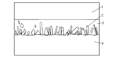
本発明品の断面組織をSEMで観察すると、図1に示すようなセラミックス相が硬質合金側に分布した接合層が観察される。本発明の接合層におけるセラミックス相粒子は針状であると接合強度が高くなるので、好ましい。具体的には、セラミックス相粒子について、((粒子の長軸の長さ)/(粒子の長軸と直交する方向の短軸の長さ))の比が最大値となる値をアスペクト比とすると、セラミックス相粒子のアスペクト比の平均値が5以上12以下であると接合強度がさらに高くなるので好ましい。その中でも長軸の長さの平均値が1μm以上30μm以下で、アスペクト比の平均値が5以上12以下であり、Tiの炭化物およびTiの炭窒化物の1種または2種からなるセラミックス相であると、さらに好ましい。
接合層におけるセラミックス相粒子のアスペクト比の平均値は断面方向における組織写真から測定することができる。具体的には、接合した複合体の接合面の表面に対して垂直な方向に切断または研削し、その切断面または研削面を鏡面加工し、SEM(走査型電子顕微鏡)にて例えば1000~5000倍で接合層を観察する。断面組織から観察される接合層のセラミックス相粒子について、((粒子の長軸の長さ)/(粒子の長軸と直交する方向の短軸の長さ))の比が最大値となる値を粒子のアスペクト比とし、その平均値を求めることができる。本発明の接合層の厚さについても、SEMにて得た断面写真から測定することができる。
本発明の複合体の製造方法としては、例えば、以下の方法を挙げることができる。まず、cBN焼結体と硬質合金と金属箔を用意する。cBN焼結体と硬質合金をそれぞれ鏡面研磨する。金属箔の厚さは10~40μmにすると好ましい。これは、金属箔の厚さが10μm未満であると接合層の厚さが2μm未満になりやすく、金属箔の厚さが40μmを超えて厚くなると接合層の厚さが30μmを超えて厚くなりやすいためである。本発明の金属箔の厚さについてはマイクロメーターで測定することができる。cBN焼結体と硬質合金をアセトンなどの有機溶剤で脱脂と洗浄を十分に行った後、金属箔をcBN焼結体と硬質合金とで挟み、ホットプレスなどの装置を用い、0.5kgf/cm2以上の接合圧力になるように荷重をかけて、例えば、真空中、窒素ガス雰囲気中、アルゴンガス雰囲気中またはアルゴン窒素混合ガス雰囲気中にて1000~1250℃で20~90分間保持した後、冷却する。これにより硬質合金の成分、例えば、C、Nなどが金属箔中に拡散し、Tiの炭化物、Tiの炭窒化物などのセラミックス相が金属箔中に形成する。このようにして得られたセラミックス相と金属相とからなる接合層を介してcBN焼結体と硬質合金は強固に接合する。なお、接合圧力は、900kgf/cm2を超えて高くなると、硬質合金が塑性変形し、形状変化が大きくなりすぎるので、0.5kgf/cm2~900kgf/cm2の範囲が好ましく、接合圧力が100kgf/cm2を超えて高くなると、大掛かりなプレス装置となるため、実用的には、接合圧力は0.5kgf/cm2~100kgf/cm2の範囲がさらに好ましく、その中でも0.5kgf/cm2~30kgf/cm2の範囲がさらに好ましい。また、本発明の接合層にはcBN焼結体の成分が固溶しても好ましい。なお、本発明の接合層を介して、硬質合金にcBN焼結体の成分が拡散し、cBN焼結体に硬質合金の成分が拡散しても好ましく、さらに強固な接合が可能となる。
接合時の温度は、1250℃を超えて高くなるとcBNが脆弱なhBN(六方晶窒化硼素)に相変態するため接合強度が低下する。一方、接合時の温度が、1000℃未満になると、接合層が形成されにくく、接合層が形成されるまで時間がかかるので経済的に不利となる。また、保持時間が20分未満であると接合層が安定して形成されにくくなり、保持時間が90分を超えて長くなると接合は可能であるが経済的ではない。そのため、接合時の接合温度は1000~1250℃、保持時間は20~90分間とすることが好ましい。その中でも、接合温度が1050~1150℃、保持時間は30~60分間であるとさらに好ましい。
接合するための装置としては前記ホットプレスに限らず、真空中もしくは不活性ガス中で昇温可能な装置であればいかなるものでもよい。硬質合金とcBN焼結体とを固定するために荷重をかけると好ましいが、昇温前に冶具などで硬質合金とcBN焼結体とを固定して昇温し、本発明の複合体を作製することも好ましい。また、ホットプレスなどで高い荷重をかけて昇温すると、硬質合金が極微小に塑性変形してcBN焼結体との密着度が増し、その結果、低温かつ短時間で接合することが可能となるので、より好ましい。
本発明の複合体の表面にCVD法、PVD法などにより被膜を被覆すると、耐摩耗性をさらに向上させることができる。本発明の複合体は、ろう付けされた従来のcBN工具よりも高温で被覆することが可能であり、そのため、本発明の被覆複合体は従来の被覆cBN焼結体よりも被膜と複合体との密着性を高くすることができる。本発明における被膜は、Ti、Zr、Hf、V、Nb、Ta、Cr、Mo、W、AlおよびSiから成る群より選択された少なくとも1種の炭化物、窒化物、炭窒化物、酸化物、硼化物およびこれらの相互固溶体から成る群より選択された少なくとも1種からなる。本発明の被膜として具体的には、TiC、TiN、Ti(C,N)、TiAlN、TiSiN、AlCrN、Al2O3などを挙げることができる。被膜は単層または2層以上の積層のいずれで構成されても好ましい。被膜の少なくとも1層は組成が異なる平均膜厚5~200nmの薄膜を交互に積層した交互積層膜でも好ましい。被膜全体の総膜厚は平均膜厚で、0.3μm未満であると耐摩耗性を向上させる効果が小さく、25μmを超えて厚くなると耐欠損性が低下する傾向がみられることから、被膜全体の総膜厚は平均膜厚で0.3~25μmであると好ましい。なお、被膜は従来からあるCVD法、PVD法によって被覆できる。
本発明の複合体は、cBN焼結体と硬質合金との接合強度が高いので、切削工具として用いると優れた切削性能を示す。切削工具として具体的には、旋削用工具、フライス用工具、ドリル、エンドミルなど挙げることができる。ろう付けの接合強度が問題となるような過酷な使用条件下においても、本発明の切削工具用複合体は使用可能であり、本発明の切削工具用複合体は優れた切削性能を示す。また、本発明の被覆複合体は、cBN焼結体と硬質合金との接合強度が高く、被膜と複合体との密着性が高いので、切削工具用被覆複合体は優れた切削性能を示す。
表1に示す組成を持つ直径30mm、厚さ1.5mmの円盤状のcBN焼結体と、表2に示す組成を持つ直径30mm、厚さ3.0mmの円盤状の硬質合金と、表3に示す厚さを持つTi箔を用意した。cBN焼結体および硬質合金について接合する面を、ダイヤモンド砥粒などを用いて鏡面研磨し、すべての試料をアセトン中で10分間超音波洗浄を行った。その後、ホットプレス装置を用いて、cBN焼結体と硬質合金の間にTi箔を挟み、試料の位置がずれないように表4に示す接合圧力になるように荷重をかけながら、真空中にて室温から表4に示す接合温度まで昇温し、表4に示す接合圧力、接合温度および保持時間で保持した後、冷却した。冷却後に荷重を下げてcBN焼結体と硬質合金とを接合した複合体を得た。

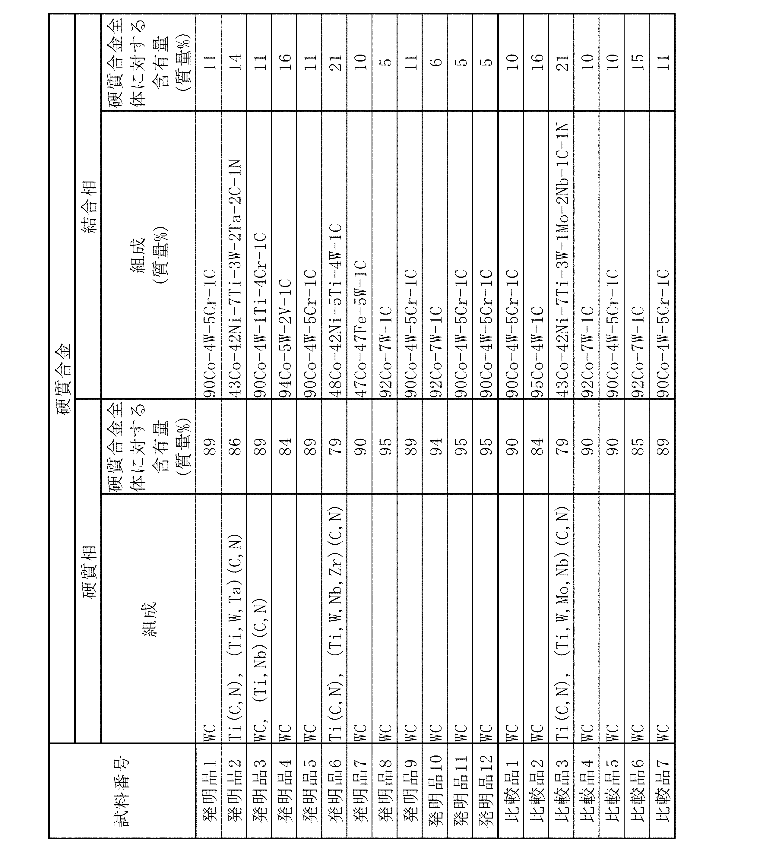
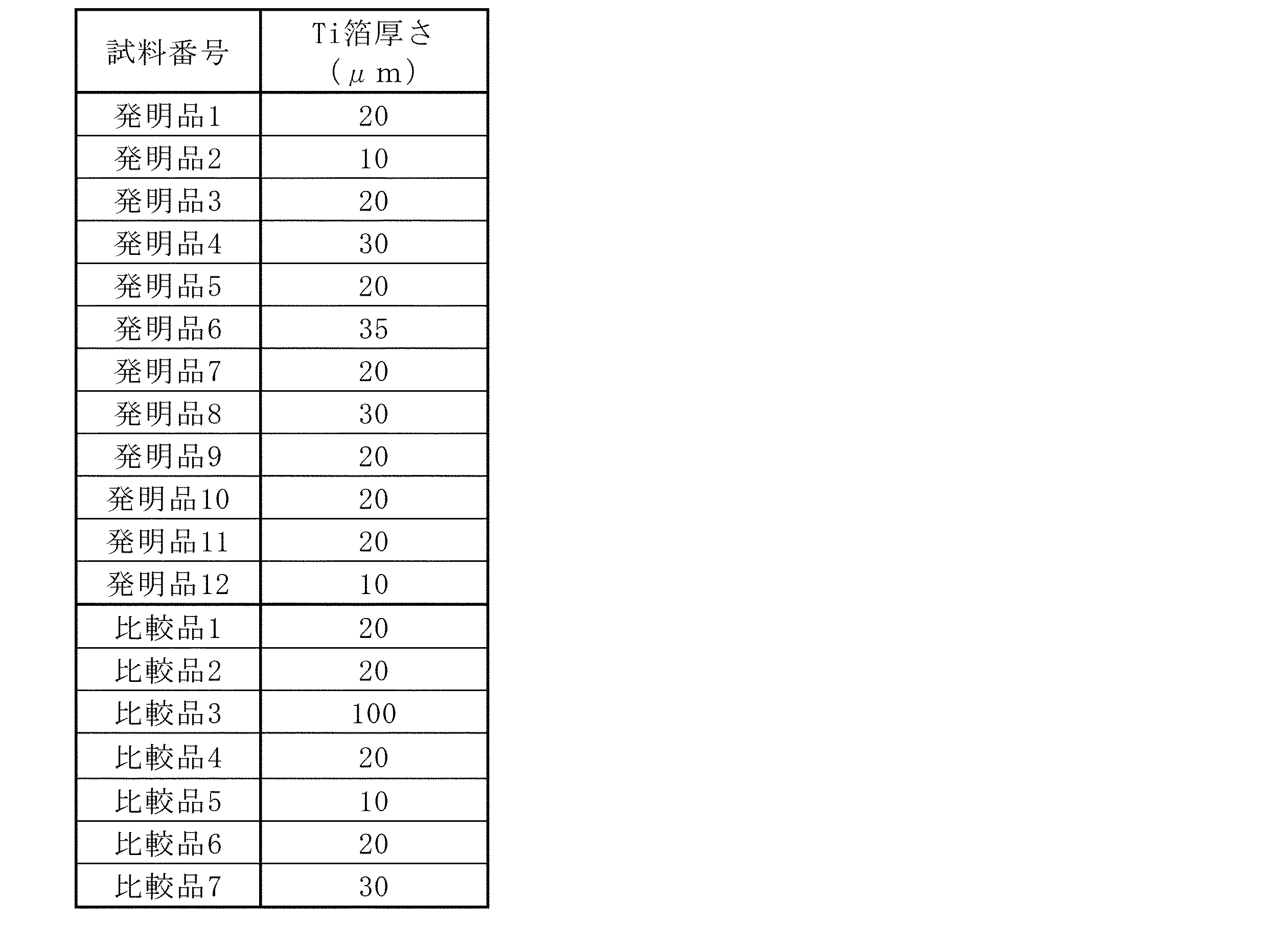
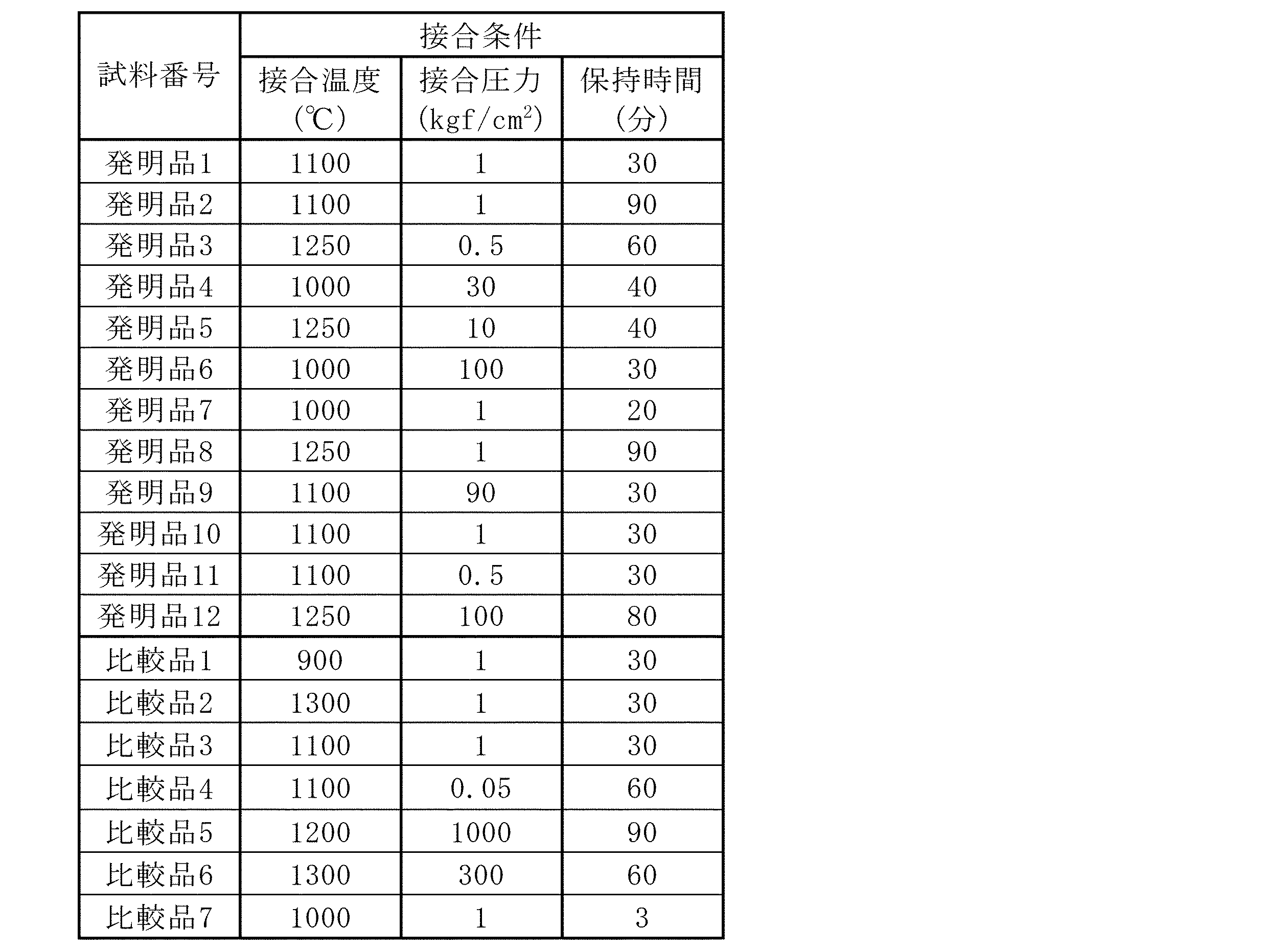
得られた複合体から10×10×4.5mmの組成分析用試験片および10×10×4.5mmのトルク試験片をワイヤカットにて切り出した。接合層の厚さとセラミックス相のアスペクト比はSEMを用いて1000~5000倍に拡大して測定した。接合層の組成はEDS(エネルギー分散型X線分析装置)により分析した。また、断面組織から、接合層のセラミックス相と金属相の面積率を測定した。また、断面組織から接合層のセラミックス相の形状、アスペクト比、長軸の長さを測定した。トルク試験は市販のトルク試験機を用い、硬質合金側を固定し、cBN焼結体側からトルクをかけ、cBN焼結体が剥離するトルク強度を測定した。各試料の接合層の厚さと組織は表5に示した。なお、表5の接合層の金属相の組成において、主要成分は個別に質量%を示したが、微量成分は合計した質量%を括弧の前に示し、括弧内に微量元素の元素名を示した。トルク強度は表6に示した。
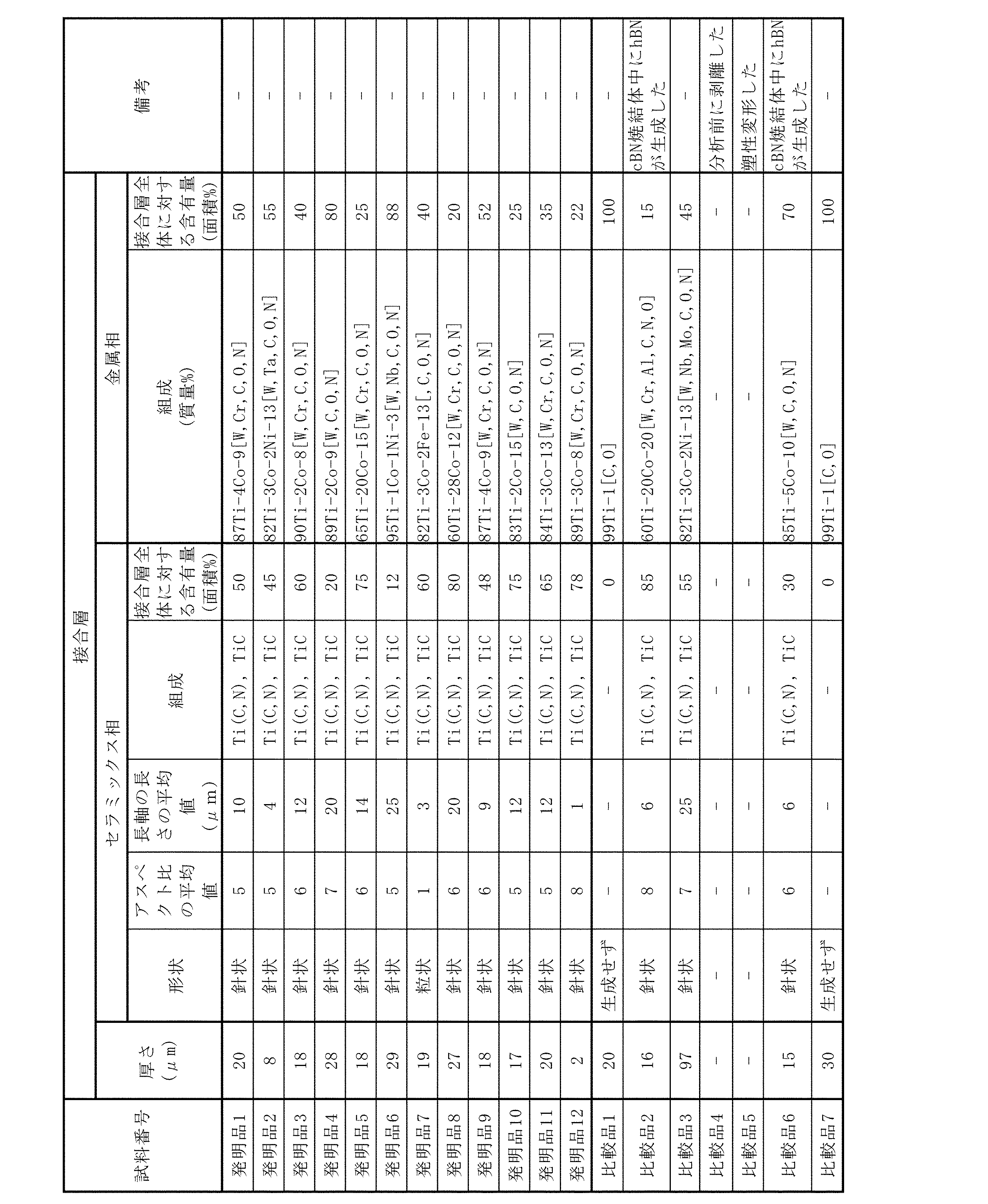
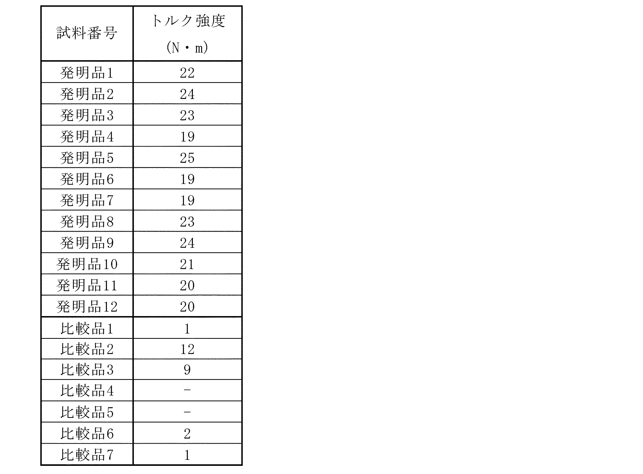
表6より発明品はトルク強度が高いことが分かる。比較品1は接合温度が低く、十分に接合層が形成されなかったため、ほとんど接合できていなかった。比較品2はトルク強度が低かった。比較品2は接合層とcBN焼結体との界面で剥離したが、cBN焼結体の剥離した面を少し研磨し、その研磨面をX線回折測定したところhBNのX線回折ピークが観察された。これは、1300℃と高温での接合であるためにcBN焼結体中のcBNがhBNに相変態したためと考えられる。すなわち、比較品2は硬さの高いcBNが硬さの低いhBNに相変態したため、トルク強度が低下したと考えられる。比較品3はTi箔厚さが厚いため、接合層厚さも厚くなり、トルク強度が低下した。比較品4は、接合圧力が低く、加熱時の密着度が不十分であったため、接合界面に隙間が発生し、剥離した。比較品5は接合圧力が高く、接合中に硬質合金が塑性変形して接合することができなかった。比較品6はトルク強度が低かった。比較品6は接合層とcBN焼結体との界面で剥離したが、cBN焼結体の剥離した面を少し研磨し、その研磨面をX線回折測定したところhBNのX線回折ピークが観察された。これは比較品2と同様に、接合温度が高く、cBN焼結体中のcBNがhBNに相変態し、トルク強度が低下したためと考えられる。比較品7は保持時間が短く、十分に接合層が形成されなかったため、トルク強度が低下した。
組成が60質量%cBN-40質量%結合相(結合相の組成:TiN、Al2O3、AlN)である直径30mm、厚さ1.5mmの円盤状のcBN焼結体と、組成が89質量%WC-11質量%結合相(結合相の組成:95質量%Co-4質量%W-1質量%C)である直径30mm、厚さ4.0mmの円盤状の硬質合金を用意し、これらの接合する面をダイヤモンド砥粒などを用いて鏡面研磨した。また、厚さ20μmのTi箔を準備した。これらの試料をアセトン中で10分間超音波洗浄を行った。その後、ホットプレス装置を用いて、cBN焼結体と硬質合金との間にTi箔を挟み、試料の位置がずれないように圧力1kgf/cm2の荷重をかけながら、真空中にて室温から1100℃まで昇温し、1100℃の接合温度で30分間保持した後、冷却した。冷却後に荷重を下げて、cBN焼結体と硬質合金とを接合した複合体を得た。得られた複合体をワイヤカットにより切り出し、研削加工によりISO規格CNGA120408形状切削インサートに加工した工具1を作製した(発明品1相当品)。また、工具1の表面にPVD法により平均膜厚3μmのTi(C,N)膜を被覆した工具2を作製した。比較品として、組成が60質量%cBN-40質量%結合相(結合相の組成:TiN、Al2O3、AlN)である直径30mm、厚さ1.5mmの円盤状のcBN焼結体から、3×3×1.5mm形状に切り出し、従来のcBN工具と同様に超硬合金製基板にろう付けし、ISO規格CNGA120408形状切削インサートに加工して工具3を得た。
工具1、2および3を用いて焼入鋼断続加工を行った。加工条件は切削速度Vc=100m/min、切り込みap=0.5mm、送りf=0.25mm/rev、クーラントは無しとし、2本のU型スロットが入った丸棒を外径旋削加工した。その結果、工具3は切削時間8分でろう付け部から大きく欠損した。一方、工具1は切削時間20分までは加工可能であったが、切削時間20分でcBN焼結体にフレーキングが発生した。しかしながら、工具1はcBN焼結体と硬質合金との接合面で剥がれることはなかった。工具2は切削時間27分でcBN焼結体にフレーキングが発生したが、工具1と同様に接合面で剥がれることはなかった。以上のように、工具1は接合強度が高く切削工具として優れた性能を発揮し工具寿命を延長することができた。工具1の表面に被膜を被覆した工具2では、さらに工具寿命を延長することができた。一方、工具3は、切削初期にろう付け部から欠損した。
本発明によれば、cBN焼結体と硬質合金との接合強度が高い複合体、およびcBN焼結体と硬質合金との接合強度が高く、被膜と複合体との密着性が高い被覆複合体を得ることができる。本発明の複合体および被覆複合体は、切削工具として用いると優れた切削性能を示す。
1 cBN焼結体
2 接合層のセラミックス相
3 接合層の金属相
4 硬質合金
2 接合層のセラミックス相
3 接合層の金属相
4 硬質合金
Claims (20)
- cBN:20~100質量%、およびTi、Zr、Hf、V、Nb、Ta、Cr、Mo、W、Co、Ni、Alの金属、これら金属の少なくとも1種の炭化物、窒化物、炭窒化物、硼化物、酸化物およびこれらの相互固溶体から成る群より選択された少なくとも1種からなる結合相:0~80質量%からなるcBN焼結体と、硬質合金と、cBN焼結体と硬質合金との間にある接合層とからなり、接合層はセラミックス相と金属相とからなり、接合層の厚さは2~30μmである複合体。
- 接合層のセラミックス相がTiの炭化物およびTiの炭窒化物の1種または2種からなる請求項1に記載の複合体。
- 接合層のセラミックス相が針状である請求項1または2に記載の複合体。
- 接合層の金属相がTiを主成分とする金属からなる請求項1~3のいずれか1項に記載の複合体。
- 接合層の金属相がCo、NiおよびFeから成る群より選択された少なくとも1種を含有するTiを主成分とする金属からなる請求項1~4のいずれか1項に記載の複合体。
- 接合層の金属相が、Ti:金属相全体に対して50~99.5質量%と、Co、NiおよびFeから成る群より選択された少なくとも1種:0.5~50質量%と、Zr、Hf、V、Nb、Ta、Cr、Mo、W、Al、C、B、OおよびNから成る群より選択された少なくとも1種:金属相全体に対して0~49.5質量%とからなる金属相である請求項1~5のいずれか1項に記載の複合体。
- 接合層の金属相が、Ti:金属相全体に対して85~99.5質量%と、Co、NiおよびFeから成る群より選択された少なくとも1種:金属相全体に対して0.5~5質量%と、Zr、Hf、V、Nb、Ta、Cr、Mo、W、Al、C、B、OおよびNから成る群より選択された少なくとも1種:金属相全体に対して0~14.5質量%とからなる金属相である請求項1~6のいずれか1項に記載の複合体。
- 硬質合金は、Ti、Zr、Hf、V、Nb、Ta、Cr、MoおよびWの炭化物、炭窒化物およびこれらの相互固溶体から成る群より選択された少なくとも1種からなる硬質相:50~97質量%と、残部として、Co、NiおよびFeから成る群より選択された少なくとも1種を主成分とする結合相:3~50質量%とからなる硬質合金である請求項1~7のいずれか1項に記載の複合体。
- 接合層が硬質合金と、cBN焼結体との間に金属箔を挟み、0.5kgf/cm2以上の接合圧力で、真空中、窒素ガス雰囲気中、アルゴンガス雰囲気中またはアルゴン窒素混合ガス雰囲気中にて1000~1250℃で20~90分間保持することにより形成されたものである請求項1~8のいずれか1項に記載の複合体。
- 金属箔の厚さが10~40μmである請求項9に記載の複合体。
- 金属箔がTi箔である請求項9または10に記載の複合体。
- 接合圧力が0.5kgf/cm2~900kgf/cm2の範囲である請求項9~11のいずれか1項に記載の複合体。
- 接合圧力が0.5kgf/cm2~100kgf/cm2の範囲である請求項9~12のいずれか1項に記載の複合体。
- 接合圧力が0.5kgf/cm2~30kgf/cm2の範囲である請求項9~13のいずれか1項に記載の複合体。
- 接合温度が1050~1150℃、保持時間が30~60分間である請求項9~14のいずれか1項に記載の複合体。
- cBN焼結体が、X線回折測定したときに、立方晶窒化硼素(cBN)以外の窒化硼素のX線回折ピークが観察されないcBN焼結体である請求項1~15のいずれか1項に記載の複合体。
- 請求項1~16のいずれか1項に記載の複合体の表面に被膜を被覆した被覆複合体。
- 被膜は、Ti、Zr、Hf、V、Nb、Ta、Cr、Mo、W、Al、Siの炭化物、窒化物、炭窒化物、酸化物、硼化物およびこれらの相互固溶体から成る群より選択された少なくとも1種からなり、被膜全体の総膜厚は平均膜厚で0.3~25μmである請求項17に記載の被覆複合体。
- 請求項1~16のいずれか1項に記載の複合体を切削工具として用いる切削工具用複合体。
- 請求項17または18に記載の被覆複合体を切削工具として用いる切削工具用被覆複合体。
Applications Claiming Priority (2)
| Application Number | Priority Date | Filing Date | Title |
|---|---|---|---|
| JP2011091933A JP2014131819A (ja) | 2011-04-18 | 2011-04-18 | 複合体 |
| JP2011-091933 | 2011-04-18 |
Publications (1)
| Publication Number | Publication Date |
|---|---|
| WO2012144502A1 true WO2012144502A1 (ja) | 2012-10-26 |
Family
ID=47041608
Family Applications (1)
| Application Number | Title | Priority Date | Filing Date |
|---|---|---|---|
| PCT/JP2012/060396 Ceased WO2012144502A1 (ja) | 2011-04-18 | 2012-04-18 | 複合体 |
Country Status (2)
| Country | Link |
|---|---|
| JP (1) | JP2014131819A (ja) |
| WO (1) | WO2012144502A1 (ja) |
Cited By (6)
| Publication number | Priority date | Publication date | Assignee | Title |
|---|---|---|---|---|
| JP2014084268A (ja) * | 2012-10-26 | 2014-05-12 | Sumitomo Electric Hardmetal Corp | 立方晶窒化ホウ素焼結体およびその製造方法 |
| GB2517569A (en) * | 2013-07-02 | 2015-02-25 | Element Six Ltd | Super-hard constructions, method for making same and method for processing same |
| WO2015146966A1 (ja) * | 2014-03-24 | 2015-10-01 | 三菱マテリアル株式会社 | 複合部材及び切削工具 |
| CN105848821A (zh) * | 2013-12-25 | 2016-08-10 | 三菱综合材料株式会社 | 接合用钎料及使用该接合用钎料的复合部件、切削工具 |
| JP6900590B1 (ja) * | 2020-03-24 | 2021-07-07 | 昭和電工株式会社 | 立方晶窒化ホウ素焼結体及びその製造方法、並びに工具 |
| WO2021192509A1 (ja) * | 2020-03-24 | 2021-09-30 | 昭和電工株式会社 | 立方晶窒化ホウ素焼結体及びその製造方法、並びに工具 |
Families Citing this family (4)
| Publication number | Priority date | Publication date | Assignee | Title |
|---|---|---|---|---|
| JP6694597B2 (ja) | 2015-08-31 | 2020-05-20 | 三菱マテリアル株式会社 | 複合部材及び切削工具 |
| KR20170108457A (ko) * | 2016-03-17 | 2017-09-27 | 일진다이아몬드(주) | 절삭공구용 복합 소결체 및 이를 이용한 절삭공구 |
| CN116987943B (zh) * | 2018-09-19 | 2025-10-10 | 住友电气工业株式会社 | 立方氮化硼烧结体以及包括该立方氮化硼烧结体的切削工具 |
| CN114290251B (zh) * | 2022-01-25 | 2022-11-08 | 长沙市萨普新材料有限公司 | 一种Fe基cBN砂轮及其制备方法 |
Citations (3)
| Publication number | Priority date | Publication date | Assignee | Title |
|---|---|---|---|---|
| JPS60172765U (ja) * | 1984-04-23 | 1985-11-15 | 住友電気工業株式会社 | 工具用複合焼結体 |
| JPH08206902A (ja) * | 1994-12-01 | 1996-08-13 | Sumitomo Electric Ind Ltd | 切削用焼結体チップおよびその製造方法 |
| JP2004291037A (ja) * | 2003-03-27 | 2004-10-21 | Mitsubishi Materials Corp | 超硬合金製部材とダイヤモンド製部材との接合方法、接合構造、掘削工具の切刃片、切刃部材、及び掘削工具 |
-
2011
- 2011-04-18 JP JP2011091933A patent/JP2014131819A/ja not_active Withdrawn
-
2012
- 2012-04-18 WO PCT/JP2012/060396 patent/WO2012144502A1/ja not_active Ceased
Patent Citations (3)
| Publication number | Priority date | Publication date | Assignee | Title |
|---|---|---|---|---|
| JPS60172765U (ja) * | 1984-04-23 | 1985-11-15 | 住友電気工業株式会社 | 工具用複合焼結体 |
| JPH08206902A (ja) * | 1994-12-01 | 1996-08-13 | Sumitomo Electric Ind Ltd | 切削用焼結体チップおよびその製造方法 |
| JP2004291037A (ja) * | 2003-03-27 | 2004-10-21 | Mitsubishi Materials Corp | 超硬合金製部材とダイヤモンド製部材との接合方法、接合構造、掘削工具の切刃片、切刃部材、及び掘削工具 |
Non-Patent Citations (1)
| Title |
|---|
| YOHEI SATO ET AL.: "Solid State Diffusion Bonding between cBN and C. C. used by insert materials", JAPAN WELDING SOCIETY ZENKOKU TAIKAI KOEN GAIYO, 28 March 2011 (2011-03-28), pages 40 - 41 * |
Cited By (19)
| Publication number | Priority date | Publication date | Assignee | Title |
|---|---|---|---|---|
| JP2014084268A (ja) * | 2012-10-26 | 2014-05-12 | Sumitomo Electric Hardmetal Corp | 立方晶窒化ホウ素焼結体およびその製造方法 |
| US9487449B2 (en) | 2012-10-26 | 2016-11-08 | Sumitomo Electric Hardmetal Corp. | Cubic boron nitride sintered body and method for manufacturing the same |
| GB2517569A (en) * | 2013-07-02 | 2015-02-25 | Element Six Ltd | Super-hard constructions, method for making same and method for processing same |
| US10626056B2 (en) | 2013-07-02 | 2020-04-21 | Element Six Limited | Super-hard constructions, methods for making same and method for processing same |
| GB2517569B (en) * | 2013-07-02 | 2015-10-14 | Element Six Ltd | Super-hard constructions, method for making same and method for processing same |
| CN105408287A (zh) * | 2013-07-02 | 2016-03-16 | 六号元素有限公司 | 超硬构造物、用于制作其的方法和用于加工其的方法 |
| CN105848821B (zh) * | 2013-12-25 | 2018-05-01 | 三菱综合材料株式会社 | 接合用钎料及使用该接合用钎料的复合部件、切削工具 |
| CN105848821A (zh) * | 2013-12-25 | 2016-08-10 | 三菱综合材料株式会社 | 接合用钎料及使用该接合用钎料的复合部件、切削工具 |
| US10252379B2 (en) | 2013-12-25 | 2019-04-09 | Mitsubishi Materials Corporation | Brazing material for bonding; and composite part and cutting tool using same |
| JP2015182161A (ja) * | 2014-03-24 | 2015-10-22 | 三菱マテリアル株式会社 | 複合部材及び切削工具 |
| EP3124147A4 (en) * | 2014-03-24 | 2017-10-25 | Mitsubishi Materials Corporation | Composite member and cutting tool |
| US10286454B2 (en) | 2014-03-24 | 2019-05-14 | Mitsubishi Materials Corporation | Composite part and cutting tool |
| WO2015146966A1 (ja) * | 2014-03-24 | 2015-10-01 | 三菱マテリアル株式会社 | 複合部材及び切削工具 |
| JP6900590B1 (ja) * | 2020-03-24 | 2021-07-07 | 昭和電工株式会社 | 立方晶窒化ホウ素焼結体及びその製造方法、並びに工具 |
| WO2021192509A1 (ja) * | 2020-03-24 | 2021-09-30 | 昭和電工株式会社 | 立方晶窒化ホウ素焼結体及びその製造方法、並びに工具 |
| KR20210119958A (ko) * | 2020-03-24 | 2021-10-06 | 쇼와 덴코 가부시키가이샤 | 입방정 질화붕소 소결체 및 그 제조 방법, 및 공구 |
| TWI747716B (zh) * | 2020-03-24 | 2021-11-21 | 日商昭和電工股份有限公司 | 立方氮化硼燒結體及其製造方法,及工具 |
| KR102373638B1 (ko) | 2020-03-24 | 2022-03-14 | 쇼와 덴코 가부시키가이샤 | 입방정 질화붕소 소결체 및 그 제조 방법, 및 공구 |
| US11427512B2 (en) | 2020-03-24 | 2022-08-30 | Showa Denko K.K. | Cubic boron nitride sintered body and manufacturing method thereof, and tool |
Also Published As
| Publication number | Publication date |
|---|---|
| JP2014131819A (ja) | 2014-07-17 |
Similar Documents
| Publication | Publication Date | Title |
|---|---|---|
| JP5678955B2 (ja) | 複合体 | |
| WO2012144502A1 (ja) | 複合体 | |
| JP5414744B2 (ja) | 立方晶窒化硼素質焼結体およびそれを用いた切削工具 | |
| JP5664795B2 (ja) | 立方晶窒化硼素焼結体 | |
| JP5614460B2 (ja) | cBN焼結体工具および被覆cBN焼結体工具 | |
| JPWO2011129422A1 (ja) | 被覆cBN焼結体 | |
| JP6245520B2 (ja) | 複合部材及び切削工具 | |
| JP2008240079A (ja) | 被覆部材 | |
| JP2002144111A (ja) | 表面被覆窒化硼素焼結体工具 | |
| JPH08104583A (ja) | 工具用複合高硬度材料 | |
| JP2012036506A (ja) | 被覆部材 | |
| WO2000047537A1 (en) | High strength sintered impact having excellent resistance to cratering | |
| JP2008254159A (ja) | 表面被覆立方晶窒化ほう素基超高圧焼結材料製切削工具 | |
| JP5187572B2 (ja) | ダイヤモンド被覆超硬合金製切削工具 | |
| KR102532558B1 (ko) | 고체 다이아몬드 재료의 코팅 방법 | |
| JP5239061B2 (ja) | 刃先横境界部の損傷を抑制する被覆cBN焼結体工具 | |
| CN121183307B (zh) | 一种多层涂层刀具及其制备方法 | |
| JPS63202444A (ja) | 超硬物質の焼結複合体 | |
| JP2008302438A (ja) | 表面被覆立方晶窒化ほう素基超高圧焼結材料製切削工具 | |
| WO2022138147A1 (ja) | 被覆工具および切削工具 | |
| CN117326873A (zh) | 立方氮化硼烧结体和涂覆立方氮化硼烧结体 | |
| WO2022138146A1 (ja) | インサートおよび切削工具 | |
| WO2022138400A1 (ja) | 被覆工具および切削工具 | |
| JP2021154460A (ja) | 表面被覆切削工具 | |
| JP2007144595A (ja) | 難削材の重切削加工で硬質被覆層がすぐれた耐チッピング性を発揮する表面被覆切削工具 |
Legal Events
| Date | Code | Title | Description |
|---|---|---|---|
| 121 | Ep: the epo has been informed by wipo that ep was designated in this application |
Ref document number: 12773958 Country of ref document: EP Kind code of ref document: A1 |
|
| NENP | Non-entry into the national phase |
Ref country code: DE |
|
| 122 | Ep: pct application non-entry in european phase |
Ref document number: 12773958 Country of ref document: EP Kind code of ref document: A1 |
|
| NENP | Non-entry into the national phase |
Ref country code: JP |