WO2012144473A1 - Dispositif de commande, système de commande de puissance et procédé de commande de puissance - Google Patents
Dispositif de commande, système de commande de puissance et procédé de commande de puissance Download PDFInfo
- Publication number
- WO2012144473A1 WO2012144473A1 PCT/JP2012/060294 JP2012060294W WO2012144473A1 WO 2012144473 A1 WO2012144473 A1 WO 2012144473A1 JP 2012060294 W JP2012060294 W JP 2012060294W WO 2012144473 A1 WO2012144473 A1 WO 2012144473A1
- Authority
- WO
- WIPO (PCT)
- Prior art keywords
- power
- power generation
- unit
- generation device
- control
- Prior art date
Links
Images


Classifications
-
- H—ELECTRICITY
- H02—GENERATION; CONVERSION OR DISTRIBUTION OF ELECTRIC POWER
- H02J—CIRCUIT ARRANGEMENTS OR SYSTEMS FOR SUPPLYING OR DISTRIBUTING ELECTRIC POWER; SYSTEMS FOR STORING ELECTRIC ENERGY
- H02J9/00—Circuit arrangements for emergency or stand-by power supply, e.g. for emergency lighting
- H02J9/002—Circuit arrangements for emergency or stand-by power supply, e.g. for emergency lighting in which a reserve is maintained in an energy source by disconnecting non-critical loads, e.g. maintaining a reserve of charge in a vehicle battery for starting an engine
-
- H—ELECTRICITY
- H02—GENERATION; CONVERSION OR DISTRIBUTION OF ELECTRIC POWER
- H02J—CIRCUIT ARRANGEMENTS OR SYSTEMS FOR SUPPLYING OR DISTRIBUTING ELECTRIC POWER; SYSTEMS FOR STORING ELECTRIC ENERGY
- H02J3/00—Circuit arrangements for ac mains or ac distribution networks
- H02J3/38—Arrangements for parallely feeding a single network by two or more generators, converters or transformers
- H02J3/381—Dispersed generators
-
- H—ELECTRICITY
- H02—GENERATION; CONVERSION OR DISTRIBUTION OF ELECTRIC POWER
- H02J—CIRCUIT ARRANGEMENTS OR SYSTEMS FOR SUPPLYING OR DISTRIBUTING ELECTRIC POWER; SYSTEMS FOR STORING ELECTRIC ENERGY
- H02J7/00—Circuit arrangements for charging or depolarising batteries or for supplying loads from batteries
- H02J7/34—Parallel operation in networks using both storage and other dc sources, e.g. providing buffering
- H02J7/35—Parallel operation in networks using both storage and other dc sources, e.g. providing buffering with light sensitive cells
-
- H—ELECTRICITY
- H02—GENERATION; CONVERSION OR DISTRIBUTION OF ELECTRIC POWER
- H02J—CIRCUIT ARRANGEMENTS OR SYSTEMS FOR SUPPLYING OR DISTRIBUTING ELECTRIC POWER; SYSTEMS FOR STORING ELECTRIC ENERGY
- H02J2300/00—Systems for supplying or distributing electric power characterised by decentralized, dispersed, or local generation
- H02J2300/20—The dispersed energy generation being of renewable origin
- H02J2300/22—The renewable source being solar energy
- H02J2300/24—The renewable source being solar energy of photovoltaic origin
-
- H—ELECTRICITY
- H02—GENERATION; CONVERSION OR DISTRIBUTION OF ELECTRIC POWER
- H02J—CIRCUIT ARRANGEMENTS OR SYSTEMS FOR SUPPLYING OR DISTRIBUTING ELECTRIC POWER; SYSTEMS FOR STORING ELECTRIC ENERGY
- H02J2300/00—Systems for supplying or distributing electric power characterised by decentralized, dispersed, or local generation
- H02J2300/30—The power source being a fuel cell
-
- Y—GENERAL TAGGING OF NEW TECHNOLOGICAL DEVELOPMENTS; GENERAL TAGGING OF CROSS-SECTIONAL TECHNOLOGIES SPANNING OVER SEVERAL SECTIONS OF THE IPC; TECHNICAL SUBJECTS COVERED BY FORMER USPC CROSS-REFERENCE ART COLLECTIONS [XRACs] AND DIGESTS
- Y02—TECHNOLOGIES OR APPLICATIONS FOR MITIGATION OR ADAPTATION AGAINST CLIMATE CHANGE
- Y02E—REDUCTION OF GREENHOUSE GAS [GHG] EMISSIONS, RELATED TO ENERGY GENERATION, TRANSMISSION OR DISTRIBUTION
- Y02E10/00—Energy generation through renewable energy sources
- Y02E10/50—Photovoltaic [PV] energy
- Y02E10/56—Power conversion systems, e.g. maximum power point trackers
Definitions
- the present invention relates to a control device that controls power supply means provided to a consumer, a power control system, and a power control method.
- the gas power generation device starts the heater or auxiliary equipment (various pumps etc.) although it wants to perform "self-sustaining operation" to supply power to the load by the gas power generation device. In the case of power failure, there is a problem that power generation can not be started.
- an object of the present invention is to provide a control device, a power control system, and a power control method capable of starting power generation by a power generation device requiring starting power during a power failure.
- the present invention has the following features.
- the control device is characterized in that the first power generation device (gas power generation device 220) requiring start-up power for starting power generation and power supply means for supplying power to the load (load 300)
- a control device for example, HEMS 700
- HEMS 700 provided in a consumer having (for example, PV 100, storage battery 200, PCS 400, distribution board 500), which controls the first power generation device and the power supply unit
- a power detection unit for detecting supply power that can be supplied by the power supply unit, and control for controlling the power supply unit so that the supply power does not fall below the activation power of the first power generation device
- a controller control unit 712A).
- control device is further provided with a power failure detection unit (power failure / stop detection unit 711C) that detects a power failure of the power system, and the control unit generates power when the power failure is detected.
- a power failure detection unit power failure / stop detection unit 711C
- the control unit When stopped, the power supply is controlled to be preferentially supplied to the first power generation device.
- control unit further includes a temperature detection unit (temperature detection unit 711B) or a stop time detection unit (power failure / stop detection unit 711C) that detects a temperature related to the first power generation device. After the start power of the first power generation device is corrected based on the temperature or the stop time, the power supply unit is controlled so that the supplied power does not fall below the corrected start power.
- a temperature detection unit temperature detection unit 711B
- a stop time detection unit power failure / stop detection unit 711C
- the self-sustaining schedule which is the operation schedule of the load during the self-sustained operation is The operation schedule determination unit (operation schedule determination unit 714A) to be determined is further provided, and the operation schedule determination unit determines the period for executing the independent operation, and the power supply condition of each of the power supply unit and the first power generation device. The schedule during the independent operation is determined based on the load condition and the load condition.
- the power supply means includes a storage battery (storage battery 200) for storing power to be supplied to a load, and the supplied power includes storage power which is power stored in the storage battery, and the control The unit controls charging and discharging of the storage battery such that the supplied power including the stored power does not fall below the start power of the first power generation device.
- a storage battery storage battery 200
- the control The unit controls charging and discharging of the storage battery such that the supplied power including the stored power does not fall below the start power of the first power generation device.
- the power supply unit further includes a second power generation device (for example, PV 100) that does not require startup power for starting power generation, and the control unit is configured to detect the power failure when the power failure is detected.
- the power obtained by the power generation of the second power generation device is set so that the supplied power satisfies the start power of the first power generation device. Control is performed to preferentially charge the storage battery.
- the first power generation device is a fuel cell device including at least one of an accessory and a heater
- the control unit is configured to send the supplied power to at least one of the accessory and the heater.
- the power supply means is controlled to be supplied.
- the features of the power control system according to the present invention include a first power generation apparatus (gas power generation apparatus 220) requiring start-up power for starting power generation, and power supply means (power supply unit) for supplying power to a load (load 300).
- a power control system provided in a consumer having a PV 100, a storage battery 200, a PCS 400, and a distribution board 500) and having a control device (for example, HEMS 700) for controlling the first power generation device and the power supply means.
- a control unit for controlling the control unit.
- a feature of the power control method according to the present invention is that, in the consumer having the first power generation device requiring start power for starting power generation and power supply means for supplying power to the load, And a power control method for controlling the power supply unit, wherein the detection step of detecting the supply power that can be supplied by the power supply unit; and the supply power is lower than the start power of the first power generation apparatus. And a control step of controlling the power supply unit.
- FIG. 1 is an overall configuration diagram of a power control system according to an embodiment of the present invention. It is a figure which shows the detailed structural example 1 of PCS which concerns on embodiment of this invention, and a distribution board. It is a figure which shows the detailed structural example 2 of PCS which concerns on embodiment of this invention, and a distribution board. It is a block diagram of HEMS which concerns on embodiment of this invention. It is a functional block diagram of the processing part of HEMS concerning the embodiment of the present invention. It is a flow chart of gas power generation start control flow by HEMS concerning an embodiment of the present invention. It is a flowchart of the self-sustaining operation control flow by HEMS which concerns on embodiment of this invention.
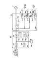
- FIG. 1 is an overall configuration diagram of a power control system according to the present embodiment.
- power lines are indicated by thick lines
- control signal lines are indicated by broken lines.
- the control signal line is not limited to wired and may be wireless.
- the power control system is configured to provide a solar battery (PV) 100, a storage battery 200, a gas power generation device 220, and a power supplier to a customer who receives supply of AC power from the power grid 1 of a power company.
- a conditioner (PCS) 400, a distribution board 500, a smart meter 600, and an HEMS 700 are provided.
- the PV 100 receives sunlight and generates power, and outputs DC power (hereinafter, PV generated power) obtained by the power generation to the PCS 400 via a power line provided between the PV 100 and the PCS 400.
- the PV 100 is configured of one or more panels.
- the PV 100 may be configured using a plurality of strings configured by a plurality of panels.
- Storage battery 200 stores power, and outputs DC power obtained by discharge (hereinafter, storage battery discharged power) to PCS 400 via a power line provided between PCS 400 and DC from PCS 400. Charge the power.
- storage battery 200 outputs information indicating stored power to PCS 400 via a control signal line provided between PCS 400 and a control signal for performing charging and discharging.
- the gas power generation device 220 is a household fuel cell that generates electric power using city gas or propane gas input via a gas line (not shown).
- the gas power generation apparatus 220 outputs DC power (hereinafter, gas generated power) obtained by the power generation to the PCS 400 via a power line provided between the gas power generation apparatus 220 and the PCS 400.
- the gas generator 220 is provided with a temperature sensor (not shown) for measuring the temperature around the gas generator 220.
- the gas power generation apparatus 220 receives a control signal for controlling power generation via a control signal line provided between the gas power generation apparatus 220 and the PCS 400, and outputs a temperature measurement value and a drive stop time to the PCS 400.
- the gas power generation device 220 corresponds to a first power generation device that requires start-up power for starting a heater or an accessory (such as various pumps).
- the gas power generation apparatus 220 is activated when AC power is input via a power line provided between the power distribution board 500 and the input AC power reaches the startup power.
- the heater includes an ignition heater, an electric heater, and the like for igniting a burner for heating a fuel cell module such as a cell stack.
- the accessories include a pump for transporting fuel, a blower, a CPU for controlling them, and the like.
- the load 300 is supplied with AC power via a power line provided between the distribution board 500 and operates by consuming the supplied AC power.
- the load 300 may be one or more than one.
- the load 300 may include not only lighting, but also household appliances such as an air conditioner, a refrigerator, and a television, but also a heat accumulator or the like. Further, the load 300 is configured to be communicable with the HEMS 700, and configured to shift to the power saving mode according to a control command from the HEMS 700.
- the PCS 400 has a function of converting DC power obtained by the power generation of the PV 100 and discharging of the storage battery 200 into AC and outputting it, and a function of converting AC power from the power system 1 into DC and outputting it.
- Such PCS 400 may be referred to as a hybrid PCS.
- the PCS 400 inputs / outputs AC power to / from the distribution board 500 via a power line provided between the PCS 400 and the distribution board 500. Further, PCS 400 outputs DC power for charging storage battery 200 to storage battery 200 through a power line provided between storage battery 200 and PCS 400.
- the PCS 400 has a DC / DC converter 410, a DC / AC converter 420, a controller 430, and a self-supporting outlet 440. However, the PCS 400 may not have the self-supporting outlet 440.
- the DC / DC converter 410 DC / DC converts the PV generated power, and outputs the DC power to the storage battery 200 and / or the DC / AC converter 420 under the control of the controller 430.
- the DC / AC converter 420 converts the DC power output from the DC / DC converter 410 and / or the storage battery discharge power into AC and outputs the AC power to the distribution board 500 under the control of the controller 430. Further, when a load is connected to the stand-alone operation outlet 440, the DC / AC converter 420 outputs AC power to the stand-alone operation outlet 440 under the control of the controller 430. Further, under the control of the controller 430, the DC / AC converter 420 converts AC power input from the distribution board 500 into DC and outputs the DC to the storage battery 200.
- the controller 430 controls various functions of the PCS 400, and is configured using a CPU and a memory.
- the controller 430 also transmits and receives various control signals to and from the HEMS 700.
- the controller 430 supplies the measured value of the PV generated power, the measured value of the gas generated power, the measured value of the power stored in the storage battery 200 (hereinafter, stored power of storage battery), and the outlet 440 for the independent operation
- the measurement values of the power being measured are acquired, and these measurement values are notified to the HEMS 700.
- the controller 430 detects the power generation stop of the gas power generation device 220, the controller 430 notifies the HEMS 700 of a control signal to that effect.
- controller 430 controls charging / discharging of storage battery 200 or adjusts PV generated power in accordance with the control command received from HEMS 700.
- the controller 430 may be connected to a user interface unit that receives an input from a user.
- the self-sustaining operating outlet 440 is for supplying power to the load during self-sustaining operation.
- the outlet 440 for self-sustaining operation is not limited to the case where it is provided in the PCS 400, and may be provided separately from the PCS 400 via a power line.
- the distribution board 500 distributes power under the control of the controller 430 and / or the HEMS 700 of the PCS 400.
- the distribution board 500 receives the AC power for the shortage from the power system 1 and receives the AC power output from the PCS 400 and the power system 1 AC power is supplied to the load 300. Further, when the AC power output from the PCS 400 exceeds the power consumption of the load 300, the distribution board 500 transmits (sells) the excess AC power to the power system 1.
- Distribution board 500 performs disconnection from electric power system 1 at the time of a power failure of electric power system 1 (hereinafter, simply referred to as “power failure”), and shifts from the interconnection operation to the autonomous operation.
- PV generated power and storage battery discharged power are supplied to load 300 via PCS 400 and distribution board 500. That is, in the present embodiment, the PV 100, the storage battery 200, the PCS 400, and the distribution board 500 constitute a power supply unit that supplies power to the load 300.
- the smart meter 600 is provided on the power line between the power system 1 and the distribution board 500, measures the selling and selling power to and from the power system 1, and notifies the measurement value to the HEMS 700.
- the smart meter 600 communicates with the external network 2 to transmit the measured value of the power sale purchase power to the external network 2 or to receive the electricity charge information and the like.
- the smart meter 600 or PCS 400 detects a power failure, it transmits a control signal to that effect to the HEMS 700.
- the HEMS 700 is for managing the power in the customer, and transmits various control commands to the PCS 400 and the distribution board 500 to control each device in the customer, and various measured values. It has a function to collect and monitor and display the status of each device in the customer.
- the HEMS 700 also determines the operation schedule of the load 300 and performs control according to the determined operation schedule.
- the HEMS 700 corresponds to a control device that controls the power supply unit (PV 100, storage battery 200, PCS 400, etc.) and the load 300.
- the HEMS 700 may acquire information used for control from the external network 2 by communicating with the external network 2.
- FIG. 2 is a view showing a detailed configuration example 1 of the PCS 400 and the distribution board 500. As shown in FIG.
- the PCS 400 has a display unit 450 and a speaker 460 in addition to the DC / DC converter 410, the DC / AC converter 420, and the controller 430.
- the display unit 450 displays that power failure is under the control of the controller 430.
- the speaker 460 performs an audio output indicating that the power failure is in progress under the control of the controller 430.
- an input unit 470 may be provided which can input an expected power failure period, which will be described later, and can specify a load priority and the like.
- the distribution board 500 has a function of performing parallel connection from the electric power system 1 and a function of switching the presence or absence of the power supply during the independent operation for each of the outlets 801 to 804.
- the distribution board 500 includes a service breaker 501, a master breaker 502, power switches 503 to 508, and a power consumption sensor CT.
- the service breaker 501, the master breaker 502, and the power switches 503 to 508 turn on / off under the control of the controller 430 of the PCS 400.
- the power sensor CT measures the power consumed by a load (for example, a light, a refrigerator) connected to the outlet 801 to 804, and notifies the controller 430 of the measured value.
- the controller 430 When power is obtained from the power system 1, the controller 430 turns on the service breaker 501 and the master breaker 502, for example, in response to a control command from the HEMS 700. As a result, power can be supplied to the loads connected to the outlets 801 to 804.
- the controller 430 when transitioning to a self-sustaining operation due to a power failure, for example, in response to a control command from the HEMS 700, the controller 430 puts the master breaker 502 in the OFF (disconnected) state while keeping the service breaker 501 in the ON state. Do. As a result, although the AC power output from the PCS 400 can be supplied to the loads connected to the outlets 801 and 802, the power can not be supplied to the loads connected to the outlets 803 and 804. It will be
- FIG. 3 is a diagram showing a detailed configuration example 2 of the PCS 400 and the distribution board 500. As shown in FIG.
- the PCS 400 according to the present configuration example is the same as the configuration example 1 in that the DC / DC converter 410, the bidirectional DC / AC converter 420, and the controller 430 are included. And 402 are different from the first configuration example.
- the distribution board 500 according to this configuration example is the same as the configuration example 1 in that the service breaker 501 and the master breaker 502 are included, but the controller 520 and the power switch 511 provided for each of the outlets 801 to 805
- the fifth embodiment differs from the first configuration example in having 515.
- the power consumption sensor S is provided for each of the outlets 801 to 805, and the controller 520 collects each measured value and notifies the controller 430 of the PCS 400. In FIG. 3, connection of signal lines between the controller 520 and the power consumption sensor S is omitted.
- the controller 430 When power is obtained from the power system 1, the controller 430 turns on each of the power switch 401, the service breaker 501, and the master breaker 502 in response to a control command from the HEMS 700, for example, and the power switch 402. Of the power switches 511 to 515 are controlled to be switched to the power system 1 side. As a result, power can be supplied to the loads connected to the outlets 801 to 805.
- the controller 430 turns off the power switch 401, the service breaker 501, and the master breaker 502 in response to a control command from the HEMS 700, for example. Control to turn on.
- the power switches 401 and 402 in the PCS 400 as in the present embodiment, power control to the load during stand-alone operation can be performed in the PCS 400.
- the controller 520 controls the power switches 511 to 515 to be sequentially (circularly) switched on as shown in the lower part of FIG. That is, in the outlets 801 to 805, control is performed so as to sequentially (circularly) allocate time for which power can be supplied. As a result, it is prevented that power is simultaneously supplied to two or more loads at a plurality of loads connected to each of the outlets 801 to 805, so that the power consumption is dispersed temporally (evening) )be able to.
- power leveling control such control is referred to as “power leveling control”.
- the time interval to be assigned may be from several minutes to several tens of minutes, and the load requiring the power supply may be continuously supplied.
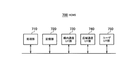
- FIG. 4 is a block diagram of the HEMS 700. As shown in FIG. 4
- the HEMS 700 includes a processing unit 710, a storage unit 720, a local communication I / F unit 730, a wide area communication I / F unit 740, and a user I / F unit 750.
- the processing unit 710, the storage unit 720, the local communication I / F unit 730, the wide area communication I / F unit 740, and the user I / F unit 750 exchange information via a bus line or a LAN.
- the processing unit 710 includes, for example, a CPU, and controls various functions of the HEMS 700 by executing a control program stored in the storage unit 720. Moreover, the processing unit 710 performs a self-sustaining operation control described later. The functional block configuration of the processing unit 710 will be described later.
- the storage unit 720 includes, for example, a RAM and a non-volatile memory, and stores various types of information used for control of the HEMS 700 and the like.
- the local communication I / F unit 730 is a communication I / F for performing communication with each device in the customer.
- the local communication I / F unit 730 performs communication by, for example, Zigbee (registered trademark) or Ethernet (registered trademark).
- the wide area communication I / F unit 740 is a communication I / F for communicating with the external network 2.
- the user I / F unit 750 includes an input unit that receives an input from the user and a display unit that performs various displays.
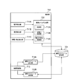
- FIG. 5 is a functional block diagram of the processing unit 710. As shown in FIG.
- the processing unit 710 includes a power detection unit 711A, a temperature detection unit 711B, a power failure / stop detection unit 711C, a control command generation unit 712, an information acquisition unit 713, an operation schedule determination unit 714A, and an operation schedule change. It has part 714B.
- the power detection unit 711A supplies the load 300 with the result of the sum of the measured value of the PV generated power and the measured value of the storage power of the storage battery. It is detected as possible power (hereinafter, power supply at the start of a power failure) and is output to the control command generation unit 712.
- the temperature detection unit 711 B detects the measurement value of the ambient temperature of the gas power generation device 220 among the measurement values received by the indoor communication I / F unit 730 from the PCS 400, and outputs the measurement value to the control command generation unit 712.
- the power failure / stop detection unit 711 C detects a power failure notification received by the local communication I / F unit 730 from the smart meter 600 (or the PCS 400), and outputs the notification to the control command generation unit 712.
- the power failure / stop detection unit 711C may detect a power failure notification received by the wide area communication I / F unit 740 from the external network 2 and output the notification to the control command generation unit 712.
- the power failure / stop detection unit 711 C detects a gas power generation stop notification received by the wide area communication I / F unit 740 from the PCS 400, and outputs the gas power generation stop notification to the control command generation unit 712. At that time, the stop time of the gas power generation device 220 may be detected and output to the control command generation unit 712.
- the control command generation unit 712 generates a control command for controlling each device in the customer, and transmits the generated control command to a target device in the customer via the local communication I / F unit 730.
- the control command generation unit 712 includes a control unit 712A, a power saving control unit 712B, and a power leveling control unit 712C.
- Control unit 712A corrects the startup power (standard value) of gas power generation device 220 based on the ambient temperature of gas power generation device 220 or the stop time of gas power generation device 220. It is assumed that the standard value of the start power of the gas power generation device 220 is stored in advance in the storage unit 720. In addition, the storage unit 720 stores in advance a start power correction value for each temperature or stop time, and the control unit 712A uses the correction value corresponding to the ambient temperature or stop time of the gas power generation apparatus 220 to start the power. Correct the standard value of. Then, control unit 712A uses the corrected startup power in the following processing.
- Control unit 712A generates a control command for controlling the charge and discharge of storage battery 200 so that the supplied power at the start of a power failure does not fall below the start-up power of gas power generation apparatus 220, and transmits the control command to wide area communication I / F unit 740. It transmits to PCS400 via.
- the controller 712A is configured such that the supplied power at the start of the power failure meets the start power of the gas generator 220; Control is performed to preferentially charge the storage battery 200 with the power obtained by the power generation of the PV 100.
- the control unit 712A gives priority to the gas power generation device 220 at the power failure start supply power, that is, the PV generated power and the stored power.
- a control command for controlling supply is generated, and the control command is transmitted to the PCS 400 and the distribution board 500 via the local communication I / F unit 730.
- the power saving control unit 712B generates a power saving control command for instructing “power saving control” to operate the load 300 in the power saving mode at the start of the stand-alone operation, and generates the power saving control command for local communication It transmits to the load 300 via the I / F unit 730.
- the power leveling control unit 712 C generates a power leveling control command for instructing the above-described power leveling control at the start of the stand-alone operation, and the generated power leveling control command is transmitted to the indoor communication I / F unit 730. To the distribution board 500.
- the information acquisition unit 713 is a variety of information for determining a schedule during autonomous operation which is an operation schedule of the load 300 during autonomous operation through the local communication I / F unit 730 and / or the wide area communication I / F unit 740. Acquire (details will be described later).
- the driving schedule determination unit 714A determines the autonomous driving schedule based on the information acquired by the information acquisition unit 713.
- Driving schedule determination unit 714 ⁇ / b> A stores the information on the determined autonomous driving schedule in driving schedule storage unit 721 provided in storage unit 720.
- the operation schedule change unit 714B changes the autonomous driving schedule stored in the operation schedule storage unit 721, and the operation before the change is performed according to the changed operation schedule. Update the schedule.
- Control command generation unit 712 generates a control command according to the operation schedule stored in operation schedule storage unit 721, and transmits the generated control command to the target device in the customer via local communication I / F unit 730. .
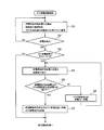
- FIG. 6 is a flowchart of a gas power generation start control flow by the HEMS 700.
- the power detection unit 711A detects the result of the sum of the measured value of the PV generated power and the measured value of the storage power of the storage battery as the power supply at the start of a power failure.
- the temperature detection unit 711B detects a measurement value of the temperature around the gas power generation device 220
- the power failure / stop detection unit 711C detects the stop time of the gas power generation device 220.
- starting power correction when the initial temperature is low or the stop time is long, it takes time to reach a predetermined temperature after the gas power generation device 220 is started, and thus the total amount of start power becomes large.
- starting power correction the amount of starting power changing in this manner.
- the control unit 712A After performing the temperature correction of the activation power of the gas power generation device 220, the control unit 712A generates a control command so that the power supply at the start of a power failure satisfies the corrected activation power. For example, when the power supply at the start of power failure does not reach the post-correction starting power, the control unit 712A generates and transmits a control command to increase stored power.
- step S 2 If the power failure / stop detection unit 711 C detects the occurrence of a power failure in step S 2 (step S 2; YES), and if the power failure / stop detection unit 711 C detects the power generation stop of the gas power generation apparatus 220 in step S 3, processing The process proceeds to step S4. If the occurrence of a power failure is not detected (step S2; NO), the process returns to step S1. If the power failure / stop detection unit 711 C detects the occurrence of a power failure (step S 2; YES), and the power failure / stop detection unit 711 C does not detect the power generation stop of the gas power generation apparatus 220 in step S 3, the process is a self-sustaining operation. Control flow (details will be described later).
- step S4 the power detection unit 711A detects the result of adding up the measured value of the PV generated power and the measured value of the storage power of the storage battery as the power supply at the start of a power failure.
- the temperature detection unit 711 B detects a measurement value of the temperature around the gas power generation device 220.
- the control unit 712A performs temperature correction of the activation power of the gas power generation device 220.
- controller 712A determines in step S5 that the power supply at the start of a power failure does not satisfy the corrected startup power (step S5; NO)
- controller 712A stores the PV generated power in storage battery 200 in step S6. Control command to be generated and sent to the PCS 400. Thereafter, the process returns to step S4.
- control unit 712A determines that the power supply at power failure start satisfies the startup power after correction at step S5 (step S5; YES)
- controller 712A supplies power at power failure start ( A control command for controlling supply of the PV generated power and the stored power to the gas generator 220 is generated and transmitted to the PCS 400 and the distribution board 500. As a result, the gas generator 220 is activated. Thereafter, the process proceeds to the autonomous operation control flow.
- FIG. 7 is a flowchart of the autonomous operation control flow by the HEMS 700.
- step S11 the information acquisition unit 713 acquires planned power outage period information, power storage information, power generation information, and power consumption information.
- the blackout scheduled period information is information indicating a blackout scheduled period defined by the planned blackout (rotational blackout), for example, a date corresponding to the blackout scheduled period, a start time of the blackout scheduled period, and an end of the blackout scheduled period And time.
- Information acquisition unit 713 acquires planned power outage period information from external network 2 via wide area communication I / F portion 740, or acquires planned power outage period information based on a user input to user I / F portion 750.
- the PCS 400 is provided with a user I / F unit (for example, the input unit 470 shown in FIG. 2)
- power failure scheduled period information is acquired based on the user input to the user I / F unit 750 of the PCS 400. May be If the smart meter 600 can acquire the power outage scheduled period information from the external network 2, the power outage planned period information may be acquired from the smart meter 600 via the local communication I / F unit 730.
- the power failure scheduled period indicated by the above-described power failure scheduled period information corresponds to a period in which the autonomous operation is performed.
- the storage information is information indicating the storage power of the storage battery 200 before the power failure (immediately before the power failure).
- Information acquisition unit 713 acquires power storage information from PCS 400 via local communication I / F unit 730.
- the power generation information is information indicating the generated power of each of the PV 100 and the gas power generator 220 before the power failure (immediately before the power failure).
- the information acquisition unit 713 acquires power generation information from the PCS 400 via the local communication I / F unit 730.
- the information acquisition unit 713 acquires the generated power indicating the predicted generated power of the PV 100 in the autonomous operation based on the information useful for obtaining the predicted generated power of the PV 100 in the future (during the autonomous operation).
- the information useful for obtaining the expected generated power is, for example, the following information.
- the information acquisition unit 713 acquires weather prediction information and weather sensor information from the external network 2 via the wide area communication I / F unit 740.
- the information acquisition unit 713 acquires information on the date and the current time of the day from the external network 2 via the internal timer of the HEMS 700 or the wide area communication I / F unit 740.
- Estimation from the amount of power generation at the start of a power failure For example, it is possible to predict future power generation according to whether the power generation at the start of a power failure (at the transition to a self-sustaining operation) is increasing or decreasing.
- Past power generation result data For example, by storing the generated power in the storage unit 720 for each environmental condition and searching for the generated power in the past that matches the current environmental conditions, it is possible to predict future generated power.
- the storage information and the power generation information described above correspond to the power supply status of the power supply unit.
- the power consumption information is information indicating the total power consumption of the load 300 before the power failure (immediately before the power failure).
- the total power consumption of the load 300 can be measured by, for example, the distribution board 500, or can be measured by the outlet to which the load 300 is connected, and the information acquisition unit 713 acquires power consumption information via the local communication I / F unit 730.
- the information acquisition unit 713 acquires power consumption information via the local communication I / F unit 730.
- the information of the said load may be acquired manually or automatically, and the power consumption information about the said load may be calculated
- a schedule during self-sustaining operation by using the above-described power cut estimated period information, power storage information, power generation information, and power consumption information. For example, it is determined how much the total power consumption of the load 300 can be covered by the total power that can be supplied to the load 300 during a power failure (during independent operation), and in the scheduled power failure period (independent operation period) The schedule as to whether to supply power to the load 300 at such timing is determined.
- the information acquisition unit 713 can more appropriately determine the autonomous driving schedule by acquiring the load priority information, the power saving mode information, the power leveling information, and the startup power information.
- the load priority information is information in which the power supply priority for the load 300 is set.
- the information acquisition unit 713 acquires load priority information based on a user input to the user I / F unit 750.
- load priority order information in a predetermined priority order may be stored in the storage unit 720, and the load priority order information may be acquired from the storage unit 720. For example, HEMS 700 and emergency lights are set to a high priority.
- the power saving mode information is information indicating power saving mode information for each load 300 (for example, the type of power saving mode and power consumption in the power saving mode).
- the power leveling information is information related to power leveling control as shown in FIG. 3 (for example, information on the load 300 to be a target of power leveling control).
- the startup power information is information indicating startup power for each load 300. For example, after power outage mode, intermittent operation as a power saving mode is performed to raise the temperature of the refrigerator, and when the electricity is restored, the start power for cooling back to the original temperature is also large. It is assumed that power consumption is lower if time is continued. Therefore, it is preferable to determine the schedule in consideration of the startup power information (also the internal temperature of the refrigerator if it can be acquired).
- step S12 the operation schedule determination unit 714A determines the power outage scheduled period information acquired by the information acquisition unit 713, power storage information, power generation information, power consumption information, load priority information, power saving mode information, power leveling information, and Based on the startup power information, a schedule during autonomous operation is determined. For example, based on the total power that can be supplied to the load 300 during a power failure (during independent operation), it is determined how much the total load power consumption including power saving control and power leveling control can be covered, In consideration of the priority of the load 300 and the starting power, a schedule is determined as to which load to which power is to be supplied at what timing in the scheduled power failure period (independent operation period).
- Table 1 shows a self-sustaining operation schedule of the load determined based on the storage information and the power generation information after inputting a planned power failure period of 2 hours.
- a schedule may be set up so that the sum of the power consumption of the gas power generating apparatus and the power consumption of the gas power generation apparatus does not exceed the amount of power generation of the storage battery and the solar cell.
- the “power leveling control” described in FIG. 3 may be performed.
- the driving schedule storage unit 721 stores the autonomous driving schedule determined by the driving schedule storage unit 721.
- step S13 the control command generation unit 712 generates a switching command to the stand-alone operation, and transmits the generated switching command to the PCS 400 and the distribution board 500 via the local communication I / F unit 730.
- the distribution board 500 may automatically switch to the stand-alone operation, or the user may manually switch to the stand-alone operation by connecting the load 300 to the stand-alone operation outlet 440.
- step S14 the control command generation unit 712 causes the control command according to the schedule information during stand-alone operation stored in the operation schedule storage unit 721 to be transmitted to the load 300, PCS 400, or the like via the indoor communication I / F unit 730. Transmit to distribution board 500.
- step S19 When self-sustaining operation is ended due to the elapse of the power outage scheduled period, the system is switched to grid connection (step S19), and the present flow ends.
- the information acquisition unit 713 reacquires power storage information, power generation information, and load priority order information in step S16.
- the storage information and the power generation information are acquired again in order to change the schedule during the autonomous operation when there is an error between the current storage power and the current generation power with respect to the initial expectation.
- the load priority information is acquired again in order to allow interruption of unscheduled load, for example, when the mobile phone needs to be charged.
- the information acquisition unit 713 may acquire human sensor information when the human sensor is provided in the consumer. For example, it is conceivable to provide a human sensor in each room, and change the operation schedule of the lighting, the air conditioner, and the like according to whether or not the user is present in the room.
- step S17 the driving schedule changing unit 714B performs the autonomous driving stored in the driving schedule storage unit 721 based on the power storage information, the power generation information, the load priority order information, and the human detection sensor information acquired by the information acquiring unit 713.
- Medium Determine whether to change the schedule.
- step S17 If it is determined that the schedule during the independent operation is not changed (step S17; NO), the process is returned to step S14.
- step S17 When it is determined that the schedule during the independent operation is changed (step S17; YES), the operation schedule changing unit 714B changes the schedule during the independent operation stored in the operation schedule storage unit 721 in step S18, and then the process is performed. It returns to step S14.
- control unit 712A controls the charge and discharge of the storage battery 200 so that the supplied power that can be supplied to the load 300 does not fall below the start power of the gas power generation device 220, thereby starting power of the gas power generation device 220. Power generation by the gas power generation apparatus 220 can be started during a power failure.
- the supply power that can be supplied to the load 300 is preferentially supplied to the gas power generation device 220. Power generation by the gas power generation apparatus 220 can be started immediately after a power failure.
- the gas power generation device 220 by determining the start power of the gas power generation device 220 based on the ambient temperature or the stop time of the gas power generation device 220, the gas power generation device 220 whose start power changes according to the temperature is made more reliable. Can be launched.
- the supply power that can be supplied to the load 300 when a power failure is detected, if the supply power that can be supplied to the load 300 does not meet the start power of the gas generator 220, the supply power that can be supplied to the load 300 is the start By preferentially charging the storage battery 200 with the power generated by the PV 100 so that the power is satisfied, the gas power generation apparatus 220 can be started early.
- the operation schedule determination unit 714A determines the schedule during the autonomous operation based on the period for executing the autonomous operation, the power supply status of the power generation device and the storage battery 200, and the status of the load 300.
- the operation schedule of the load 300 can be appropriately determined during a power failure (i.e., during self-sustaining operation).
- the operation schedule determination unit 714A can determine the operation schedule of the load 300 during a power failure (that is, during the independent operation) by determining the schedule during the independent operation at the start of the independent operation.
- the operation schedule determination unit 714A determines the period during which the self-sustaining operation is performed, the power supply status of the power generation device and the storage battery 200 before determining the self-sustaining schedule, and
- the autonomous driving schedule can be determined according to the latest status by determining the autonomous driving schedule based on the load 300 status.
- the operation schedule determination unit 714A can supply power to the load 300 with an appropriate priority by determining the schedule during the autonomous operation based further on the setting of the power supply priority for the load 300.
- the driving schedule determination unit 714A can appropriately determine the autonomous driving schedule in consideration of the electric power saving control during the autonomous operation by determining the autonomous driving schedule based further on the electric power saving control. .
- the operation schedule determination unit 714A determines the autonomous driving schedule appropriately in consideration of the electric power equalization control during the autonomous operation by further determining the autonomous driving schedule based on the electric power equalization control. It can be decided.
- the operation schedule changing unit 714B is based on at least one of the power supply status of the power generation device and the storage battery 200 during the autonomous operation, the status of the load 300 during the autonomous operation, or the status of the user during the autonomous operation. By changing at least a part of the determined autonomous driving schedule, the autonomous driving schedule can be appropriately changed during autonomous operation.
- the configuration in which the PV 100, the gas power generation device 220, and the storage battery 200 are provided to the consumer has been described, but the PV 100 or the storage battery 200 may not be provided to the consumer.
- a wind power generation apparatus may be provided to a consumer.
- the PV 100 and the wind turbine generator correspond to a second power generator which does not require startup power to start power generation.
- power is required for the first drive, and the driven transition generates power by a supply other than the power (resources other than gas such as petroleum).
- the device may be a first power generation device.
- the HEMS 700 for performing power management in units of houses has been described as an example in the embodiment described above, the HEMS 700 may be replaced by BEMS for performing power management in units of buildings.
- the configuration of the HEMS 700 illustrated in FIG. 5 may be provided in the controller 430 of the PCS 400, and at least a part of the processing flow illustrated in FIGS. 6 and 7 may be executed by the controller 430 of the PCS 400. That is, the PCS 400 may be used as a control device according to the present invention.
- the schedule during the autonomous operation is determined before switching to the autonomous operation, but the schedule during the autonomous operation may be determined after switching to the autonomous operation.
- control device As described above, the control device, the power control system, and the power control method according to the present invention are useful in the field of power since power generation by a power generation device requiring starting power can be started during a power failure.
Abstract
Priority Applications (4)
| Application Number | Priority Date | Filing Date | Title |
|---|---|---|---|
| EP12774469.6A EP2701264B1 (fr) | 2011-04-18 | 2012-04-16 | Dispositif de commande, système de commande de puissance et procédé de commande de puissance |
| CN201280018767.6A CN103477527B (zh) | 2011-04-18 | 2012-04-16 | 控制设备、电力控制系统和电力控制方法 |
| US14/112,515 US10243396B2 (en) | 2011-04-18 | 2012-04-16 | Control device, power control system, and power control method |
| JP2013511003A JP5730990B2 (ja) | 2011-04-18 | 2012-04-16 | 制御装置、電力制御システム、及び電力制御方法 |
Applications Claiming Priority (2)
| Application Number | Priority Date | Filing Date | Title |
|---|---|---|---|
| JP2011092528 | 2011-04-18 | ||
| JP2011-092528 | 2011-04-18 |
Publications (1)
| Publication Number | Publication Date |
|---|---|
| WO2012144473A1 true WO2012144473A1 (fr) | 2012-10-26 |
Family
ID=47041579
Family Applications (1)
| Application Number | Title | Priority Date | Filing Date |
|---|---|---|---|
| PCT/JP2012/060294 WO2012144473A1 (fr) | 2011-04-18 | 2012-04-16 | Dispositif de commande, système de commande de puissance et procédé de commande de puissance |
Country Status (5)
| Country | Link |
|---|---|
| US (1) | US10243396B2 (fr) |
| EP (1) | EP2701264B1 (fr) |
| JP (2) | JP5730990B2 (fr) |
| CN (1) | CN103477527B (fr) |
| WO (1) | WO2012144473A1 (fr) |
Cited By (13)
| Publication number | Priority date | Publication date | Assignee | Title |
|---|---|---|---|---|
| JP2014096927A (ja) * | 2012-11-09 | 2014-05-22 | Nyk Trading Corp | 電源供給システム及び装置 |
| WO2014092195A1 (fr) * | 2012-12-10 | 2014-06-19 | 日本電気株式会社 | Système de génération de puissance distribuée, station de commande, et procédé de commande pour celle-ci |
| JP2014165954A (ja) * | 2013-02-21 | 2014-09-08 | Tokyo Gas Co Ltd | 給電システム、給電制御プログラムおよび給電制御方法 |
| JP2014171375A (ja) * | 2013-03-05 | 2014-09-18 | Tokyo Gas Co Ltd | 給電システム、給電プログラムおよび給電方法 |
| JP2014233136A (ja) * | 2013-05-29 | 2014-12-11 | 三菱電機株式会社 | エネルギーマネジメントシステム及び運転計画作成方法 |
| JP2014236601A (ja) * | 2013-06-03 | 2014-12-15 | 石田 秀樹 | 制御装置及び電力デマンド抑制システム |
| JP2015032221A (ja) * | 2013-08-05 | 2015-02-16 | 大阪瓦斯株式会社 | エネルギー管理システム |
| JP2015133871A (ja) * | 2014-01-15 | 2015-07-23 | 京セラ株式会社 | 電力変換装置、発電装置及び電力変換システム |
| EP2889981A3 (fr) * | 2013-11-04 | 2015-08-12 | Kiwigrid GmbH | Procédé de commande d'une distribution d'énergie |
| JP2015148440A (ja) * | 2015-05-29 | 2015-08-20 | 三菱電機株式会社 | 冷蔵庫システム |
| EP3024119A1 (fr) * | 2013-07-17 | 2016-05-25 | Kyocera Corporation | Dispositif de commande, tableau de distribution et procédé de commande |
| US10312807B2 (en) | 2014-11-27 | 2019-06-04 | Kyocera Corporation | Power control apparatus, power supply system, and method for controlling power supply system |
| JP2019534660A (ja) * | 2016-09-29 | 2019-11-28 | トキタエ エルエルシー | 温度制御容器システムを含む冷蔵デバイスと共に使用するためのデバイス及び方法 |
Families Citing this family (16)
| Publication number | Priority date | Publication date | Assignee | Title |
|---|---|---|---|---|
| JP5837322B2 (ja) * | 2011-04-18 | 2015-12-24 | 京セラ株式会社 | 制御装置、電力制御システム、及び電力制御方法 |
| WO2013015374A1 (fr) | 2011-07-26 | 2013-01-31 | 京セラ株式会社 | Système d'alimentation électrique, dispositif de distribution et dispositif de commande électrique |
| US9455572B2 (en) * | 2012-04-27 | 2016-09-27 | Marvin A Motsenbocker | Voltage prioritization of solar loads |
| US9429925B2 (en) * | 2014-01-15 | 2016-08-30 | Haier Us Appliance Solutions, Inc. | Method for operating an appliance and a refrigerator appliance |
| KR101516802B1 (ko) * | 2014-05-16 | 2015-05-04 | 케이씨코트렐 주식회사 | 독립형 마이크로그리드용 배전반 |
| US10418819B2 (en) * | 2014-07-29 | 2019-09-17 | Kyocera Corporation | Control method for power control system, power control system, and power control apparatus |
| WO2017073079A1 (fr) * | 2015-10-28 | 2017-05-04 | 京セラ株式会社 | Dispositif de contrôle de puissance, procédé de contrôle pour dispositif de contrôle de puissance, système de contrôle de puissance et procédé de contrôle pour système de contrôle de puissance |
| KR101644522B1 (ko) * | 2015-11-20 | 2016-08-01 | 케이씨코트렐 주식회사 | Ac 마이크로그리드 3상부하에서의 전력 공급 시스템 |
| JP6535585B2 (ja) * | 2015-11-27 | 2019-06-26 | リンナイ株式会社 | 停電検知システム |
| US11611220B2 (en) * | 2015-12-31 | 2023-03-21 | Present Power Systems, Llc | Systems and methods for connecting energy sources to power distribution network |
| CN206438953U (zh) * | 2016-01-23 | 2017-08-25 | 张誉馨 | 一种安装有可电控通风设施的门 |
| DE102017112663A1 (de) * | 2017-06-08 | 2018-12-13 | Vorwerk & Co. Interholding Gmbh | Verfahren zum Betrieb eines einen Akkumulator aufweisenden Haushaltsgerätes |
| JP7113693B2 (ja) * | 2018-07-31 | 2022-08-05 | 大阪瓦斯株式会社 | 電力供給システム |
| JP7002011B2 (ja) * | 2019-02-26 | 2022-01-20 | パナソニックIpマネジメント株式会社 | 電力システムおよびその制御方法 |
| EP4097818A4 (fr) * | 2020-01-28 | 2024-04-17 | Enphase Energy Inc | Procédé et appareil de génération de valeur relative de ressources sur la base de problèmes du sac à dos |
| WO2023223434A1 (fr) * | 2022-05-17 | 2023-11-23 | オムロン株式会社 | Système d'alimentation électrique, tableau de distribution de charge complète, dispositif d'alimentation électrique, procédé de commande d'alimentation électrique pour dispositif d'alimentation électrique, trajet d'alimentation électrique, dispositif de conversion de puissance, et procédé de connexion |
Citations (5)
| Publication number | Priority date | Publication date | Assignee | Title |
|---|---|---|---|---|
| JPH1169634A (ja) | 1997-08-28 | 1999-03-09 | Tokyo Gas Co Ltd | 受電電力制御装置 |
| JP2003068339A (ja) * | 2001-08-30 | 2003-03-07 | Nissan Motor Co Ltd | 移動体用燃料電池パワープラント |
| JP2008022650A (ja) * | 2006-07-13 | 2008-01-31 | Univ Of Tsukuba | 自立運転支援装置及び電源システム |
| WO2008152798A1 (fr) * | 2007-06-13 | 2008-12-18 | National Institute Of Information And Communications Technology | Réseau domestique, réseau d'antennes l'utilisant, programme pour faire fonctionner un ordinateur dans le réseau domestique et support d'enregistrement lisible par ordinateur contenant le programme |
| JP2009232670A (ja) * | 2008-02-29 | 2009-10-08 | Osaka Gas Co Ltd | エネルギ供給システム |
Family Cites Families (10)
| Publication number | Priority date | Publication date | Assignee | Title |
|---|---|---|---|---|
| US4982569A (en) * | 1983-03-25 | 1991-01-08 | Ormat Turbines, Ltd. | Parallel hybrid system for generating power |
| JP2002063927A (ja) | 2000-08-23 | 2002-02-28 | Sanyo Electric Co Ltd | 燃料電池システムの制御方法及びその装置 |
| JP2002152976A (ja) | 2000-11-13 | 2002-05-24 | Sharp Corp | 分散電源電力供給システム |
| JP2003092844A (ja) * | 2001-09-20 | 2003-03-28 | Fujitsu General Ltd | 自家電力供給制御システム |
| JP2004328960A (ja) | 2003-04-28 | 2004-11-18 | Misawa Homes Co Ltd | 無停電電力供給装置 |
| US20050200205A1 (en) * | 2004-01-30 | 2005-09-15 | Winn David W. | On-site power generation system with redundant uninterruptible power supply |
| JP5372313B2 (ja) * | 2006-02-03 | 2013-12-18 | Jx日鉱日石エネルギー株式会社 | 燃料電池装置を有する電源システム |
| JP4868884B2 (ja) | 2006-02-23 | 2012-02-01 | Jx日鉱日石エネルギー株式会社 | 燃料電池を用いた非常電源システム |
| JP5021375B2 (ja) * | 2007-06-11 | 2012-09-05 | イビデングリーンテック株式会社 | 斜面の緑化と安定化構造 |
| JP5308268B2 (ja) | 2009-08-05 | 2013-10-09 | 本田技研工業株式会社 | 電力供給システム |
-
2012
- 2012-04-16 EP EP12774469.6A patent/EP2701264B1/fr active Active
- 2012-04-16 CN CN201280018767.6A patent/CN103477527B/zh active Active
- 2012-04-16 US US14/112,515 patent/US10243396B2/en active Active
- 2012-04-16 JP JP2013511003A patent/JP5730990B2/ja active Active
- 2012-04-16 WO PCT/JP2012/060294 patent/WO2012144473A1/fr active Application Filing
-
2015
- 2015-03-09 JP JP2015046531A patent/JP6001712B2/ja active Active
Patent Citations (5)
| Publication number | Priority date | Publication date | Assignee | Title |
|---|---|---|---|---|
| JPH1169634A (ja) | 1997-08-28 | 1999-03-09 | Tokyo Gas Co Ltd | 受電電力制御装置 |
| JP2003068339A (ja) * | 2001-08-30 | 2003-03-07 | Nissan Motor Co Ltd | 移動体用燃料電池パワープラント |
| JP2008022650A (ja) * | 2006-07-13 | 2008-01-31 | Univ Of Tsukuba | 自立運転支援装置及び電源システム |
| WO2008152798A1 (fr) * | 2007-06-13 | 2008-12-18 | National Institute Of Information And Communications Technology | Réseau domestique, réseau d'antennes l'utilisant, programme pour faire fonctionner un ordinateur dans le réseau domestique et support d'enregistrement lisible par ordinateur contenant le programme |
| JP2009232670A (ja) * | 2008-02-29 | 2009-10-08 | Osaka Gas Co Ltd | エネルギ供給システム |
Non-Patent Citations (1)
| Title |
|---|
| See also references of EP2701264A4 |
Cited By (18)
| Publication number | Priority date | Publication date | Assignee | Title |
|---|---|---|---|---|
| JP2014096927A (ja) * | 2012-11-09 | 2014-05-22 | Nyk Trading Corp | 電源供給システム及び装置 |
| JPWO2014092195A1 (ja) * | 2012-12-10 | 2017-01-12 | 日本電気株式会社 | 分散型発電システム、制御局、及びその制御方法 |
| WO2014092195A1 (fr) * | 2012-12-10 | 2014-06-19 | 日本電気株式会社 | Système de génération de puissance distribuée, station de commande, et procédé de commande pour celle-ci |
| US10389116B2 (en) | 2012-12-10 | 2019-08-20 | Nec Corporation | Distributed electric power generation system, control station, and method of controlling the same |
| JP2014165954A (ja) * | 2013-02-21 | 2014-09-08 | Tokyo Gas Co Ltd | 給電システム、給電制御プログラムおよび給電制御方法 |
| JP2014171375A (ja) * | 2013-03-05 | 2014-09-18 | Tokyo Gas Co Ltd | 給電システム、給電プログラムおよび給電方法 |
| JP2014233136A (ja) * | 2013-05-29 | 2014-12-11 | 三菱電機株式会社 | エネルギーマネジメントシステム及び運転計画作成方法 |
| JP2014236601A (ja) * | 2013-06-03 | 2014-12-15 | 石田 秀樹 | 制御装置及び電力デマンド抑制システム |
| EP3024119A4 (fr) * | 2013-07-17 | 2017-03-29 | Kyocera Corporation | Dispositif de commande, tableau de distribution et procédé de commande |
| EP3024119A1 (fr) * | 2013-07-17 | 2016-05-25 | Kyocera Corporation | Dispositif de commande, tableau de distribution et procédé de commande |
| US10673233B2 (en) | 2013-07-17 | 2020-06-02 | Kyocera Corporation | Control device, distribution board, and control method |
| JP2015032221A (ja) * | 2013-08-05 | 2015-02-16 | 大阪瓦斯株式会社 | エネルギー管理システム |
| EP2889981A3 (fr) * | 2013-11-04 | 2015-08-12 | Kiwigrid GmbH | Procédé de commande d'une distribution d'énergie |
| JP2015133871A (ja) * | 2014-01-15 | 2015-07-23 | 京セラ株式会社 | 電力変換装置、発電装置及び電力変換システム |
| US10312807B2 (en) | 2014-11-27 | 2019-06-04 | Kyocera Corporation | Power control apparatus, power supply system, and method for controlling power supply system |
| JP2015148440A (ja) * | 2015-05-29 | 2015-08-20 | 三菱電機株式会社 | 冷蔵庫システム |
| JP2019534660A (ja) * | 2016-09-29 | 2019-11-28 | トキタエ エルエルシー | 温度制御容器システムを含む冷蔵デバイスと共に使用するためのデバイス及び方法 |
| JP7007376B2 (ja) | 2016-09-29 | 2022-01-24 | トキタエ エルエルシー | 温度制御容器システムを含む冷蔵デバイスと共に使用するためのデバイス及び方法 |
Also Published As
| Publication number | Publication date |
|---|---|
| JP2015144561A (ja) | 2015-08-06 |
| CN103477527A (zh) | 2013-12-25 |
| CN103477527B (zh) | 2015-12-09 |
| JP6001712B2 (ja) | 2016-10-05 |
| JPWO2012144473A1 (ja) | 2014-07-28 |
| US20140049053A1 (en) | 2014-02-20 |
| US10243396B2 (en) | 2019-03-26 |
| JP5730990B2 (ja) | 2015-06-10 |
| EP2701264A4 (fr) | 2014-10-15 |
| EP2701264B1 (fr) | 2015-12-16 |
| EP2701264A1 (fr) | 2014-02-26 |
Similar Documents
| Publication | Publication Date | Title |
|---|---|---|
| WO2012144473A1 (fr) | Dispositif de commande, système de commande de puissance et procédé de commande de puissance | |
| JP5837322B2 (ja) | 制御装置、電力制御システム、及び電力制御方法 | |
| EP2793345B1 (fr) | Système d'alimentation électrique | |
| JP5917896B2 (ja) | 電力管理システム | |
| JP5466911B2 (ja) | 電力供給システム及び電力供給システムの制御装置 | |
| JP5890513B2 (ja) | 制御装置、制御システム及び蓄電池制御方法 | |
| US20150270745A1 (en) | Power-supply control system, control device and control method | |
| JP5719714B2 (ja) | 起動制御方法、系統連系装置、及び制御装置 | |
| EP2983265B1 (fr) | Dispositif de conversion de puissance électrique, système de commande et procédé de commande | |
| US9620990B2 (en) | Electricity supply management device | |
| WO2011055186A1 (fr) | Systeme de distribution d'energie | |
| JP2011101529A (ja) | 配電システム | |
| JP2011250673A (ja) | エネルギーコントローラおよび制御方法 | |
| JP2012147621A (ja) | 停電救済システム | |
| JP2009232668A (ja) | 電力供給システムおよび電力供給方法 | |
| US9846418B2 (en) | Energy control system, energy control device, and energy control method for prioritizing a power generation source based on the possibility of selling generated power | |
| JP2011083088A (ja) | 直流配電システム | |
| WO2011055192A1 (fr) | Système de gestion d'alimentation | |
| JP6355017B2 (ja) | 電源制御装置及び電源制御方法 | |
| JP6639187B2 (ja) | 電気自動車用パワーコンディショナ | |
| TWI443490B (zh) | 具電能管理功能之供電系統及其管理方法 | |
| CN117097020A (zh) | 配电网关、配电网关系统及配电网关的控制方法 |
Legal Events
| Date | Code | Title | Description |
|---|---|---|---|
| 121 | Ep: the epo has been informed by wipo that ep was designated in this application |
Ref document number: 12774469 Country of ref document: EP Kind code of ref document: A1 |
|
| ENP | Entry into the national phase |
Ref document number: 2013511003 Country of ref document: JP Kind code of ref document: A |
|
| WWE | Wipo information: entry into national phase |
Ref document number: 14112515 Country of ref document: US |
|
| NENP | Non-entry into the national phase |
Ref country code: DE |
|
| WWE | Wipo information: entry into national phase |
Ref document number: 2012774469 Country of ref document: EP |