WO2012144473A1 - Control device, power control system, and power control method - Google Patents

Control device, power control system, and power control method Download PDF

Info

Publication number
WO2012144473A1
WO2012144473A1 PCT/JP2012/060294 JP2012060294W WO2012144473A1 WO 2012144473 A1 WO2012144473 A1 WO 2012144473A1 JP 2012060294 W JP2012060294 W JP 2012060294W WO 2012144473 A1 WO2012144473 A1 WO 2012144473A1
Authority
WO
WIPO (PCT)
Prior art keywords
power
power generation
unit
generation device
control
Prior art date
Application number
PCT/JP2012/060294
Other languages
French (fr)
Japanese (ja)
Inventor
井上 裕司
Original Assignee
京セラ株式会社
Priority date (The priority date is an assumption and is not a legal conclusion. Google has not performed a legal analysis and makes no representation as to the accuracy of the date listed.)
Filing date
Publication date
Application filed by 京セラ株式会社 filed Critical 京セラ株式会社
Priority to US14/112,515 priority Critical patent/US10243396B2/en
Priority to JP2013511003A priority patent/JP5730990B2/en
Priority to EP12774469.6A priority patent/EP2701264B1/en
Priority to CN201280018767.6A priority patent/CN103477527B/en
Publication of WO2012144473A1 publication Critical patent/WO2012144473A1/en

Links

Images

Classifications

    • HELECTRICITY
    • H02GENERATION; CONVERSION OR DISTRIBUTION OF ELECTRIC POWER
    • H02JCIRCUIT ARRANGEMENTS OR SYSTEMS FOR SUPPLYING OR DISTRIBUTING ELECTRIC POWER; SYSTEMS FOR STORING ELECTRIC ENERGY
    • H02J9/00Circuit arrangements for emergency or stand-by power supply, e.g. for emergency lighting
    • H02J9/002Circuit arrangements for emergency or stand-by power supply, e.g. for emergency lighting in which a reserve is maintained in an energy source by disconnecting non-critical loads, e.g. maintaining a reserve of charge in a vehicle battery for starting an engine
    • HELECTRICITY
    • H02GENERATION; CONVERSION OR DISTRIBUTION OF ELECTRIC POWER
    • H02JCIRCUIT ARRANGEMENTS OR SYSTEMS FOR SUPPLYING OR DISTRIBUTING ELECTRIC POWER; SYSTEMS FOR STORING ELECTRIC ENERGY
    • H02J3/00Circuit arrangements for ac mains or ac distribution networks
    • H02J3/38Arrangements for parallely feeding a single network by two or more generators, converters or transformers
    • H02J3/381Dispersed generators
    • HELECTRICITY
    • H02GENERATION; CONVERSION OR DISTRIBUTION OF ELECTRIC POWER
    • H02JCIRCUIT ARRANGEMENTS OR SYSTEMS FOR SUPPLYING OR DISTRIBUTING ELECTRIC POWER; SYSTEMS FOR STORING ELECTRIC ENERGY
    • H02J7/00Circuit arrangements for charging or depolarising batteries or for supplying loads from batteries
    • H02J7/34Parallel operation in networks using both storage and other dc sources, e.g. providing buffering
    • H02J7/35Parallel operation in networks using both storage and other dc sources, e.g. providing buffering with light sensitive cells
    • HELECTRICITY
    • H02GENERATION; CONVERSION OR DISTRIBUTION OF ELECTRIC POWER
    • H02JCIRCUIT ARRANGEMENTS OR SYSTEMS FOR SUPPLYING OR DISTRIBUTING ELECTRIC POWER; SYSTEMS FOR STORING ELECTRIC ENERGY
    • H02J2300/00Systems for supplying or distributing electric power characterised by decentralized, dispersed, or local generation
    • H02J2300/20The dispersed energy generation being of renewable origin
    • H02J2300/22The renewable source being solar energy
    • H02J2300/24The renewable source being solar energy of photovoltaic origin
    • HELECTRICITY
    • H02GENERATION; CONVERSION OR DISTRIBUTION OF ELECTRIC POWER
    • H02JCIRCUIT ARRANGEMENTS OR SYSTEMS FOR SUPPLYING OR DISTRIBUTING ELECTRIC POWER; SYSTEMS FOR STORING ELECTRIC ENERGY
    • H02J2300/00Systems for supplying or distributing electric power characterised by decentralized, dispersed, or local generation
    • H02J2300/30The power source being a fuel cell
    • YGENERAL TAGGING OF NEW TECHNOLOGICAL DEVELOPMENTS; GENERAL TAGGING OF CROSS-SECTIONAL TECHNOLOGIES SPANNING OVER SEVERAL SECTIONS OF THE IPC; TECHNICAL SUBJECTS COVERED BY FORMER USPC CROSS-REFERENCE ART COLLECTIONS [XRACs] AND DIGESTS
    • Y02TECHNOLOGIES OR APPLICATIONS FOR MITIGATION OR ADAPTATION AGAINST CLIMATE CHANGE
    • Y02EREDUCTION OF GREENHOUSE GAS [GHG] EMISSIONS, RELATED TO ENERGY GENERATION, TRANSMISSION OR DISTRIBUTION
    • Y02E10/00Energy generation through renewable energy sources
    • Y02E10/50Photovoltaic [PV] energy
    • Y02E10/56Power conversion systems, e.g. maximum power point trackers

Definitions

  • the present invention relates to a control device that controls power supply means provided to a consumer, a power control system, and a power control method.
  • the gas power generation device starts the heater or auxiliary equipment (various pumps etc.) although it wants to perform "self-sustaining operation" to supply power to the load by the gas power generation device. In the case of power failure, there is a problem that power generation can not be started.
  • an object of the present invention is to provide a control device, a power control system, and a power control method capable of starting power generation by a power generation device requiring starting power during a power failure.
  • the present invention has the following features.
  • the control device is characterized in that the first power generation device (gas power generation device 220) requiring start-up power for starting power generation and power supply means for supplying power to the load (load 300)
  • a control device for example, HEMS 700
  • HEMS 700 provided in a consumer having (for example, PV 100, storage battery 200, PCS 400, distribution board 500), which controls the first power generation device and the power supply unit
  • a power detection unit for detecting supply power that can be supplied by the power supply unit, and control for controlling the power supply unit so that the supply power does not fall below the activation power of the first power generation device
  • a controller control unit 712A).
  • control device is further provided with a power failure detection unit (power failure / stop detection unit 711C) that detects a power failure of the power system, and the control unit generates power when the power failure is detected.
  • a power failure detection unit power failure / stop detection unit 711C
  • the control unit When stopped, the power supply is controlled to be preferentially supplied to the first power generation device.
  • control unit further includes a temperature detection unit (temperature detection unit 711B) or a stop time detection unit (power failure / stop detection unit 711C) that detects a temperature related to the first power generation device. After the start power of the first power generation device is corrected based on the temperature or the stop time, the power supply unit is controlled so that the supplied power does not fall below the corrected start power.
  • a temperature detection unit temperature detection unit 711B
  • a stop time detection unit power failure / stop detection unit 711C
  • the self-sustaining schedule which is the operation schedule of the load during the self-sustained operation is The operation schedule determination unit (operation schedule determination unit 714A) to be determined is further provided, and the operation schedule determination unit determines the period for executing the independent operation, and the power supply condition of each of the power supply unit and the first power generation device. The schedule during the independent operation is determined based on the load condition and the load condition.
  • the power supply means includes a storage battery (storage battery 200) for storing power to be supplied to a load, and the supplied power includes storage power which is power stored in the storage battery, and the control The unit controls charging and discharging of the storage battery such that the supplied power including the stored power does not fall below the start power of the first power generation device.
  • a storage battery storage battery 200
  • the control The unit controls charging and discharging of the storage battery such that the supplied power including the stored power does not fall below the start power of the first power generation device.
  • the power supply unit further includes a second power generation device (for example, PV 100) that does not require startup power for starting power generation, and the control unit is configured to detect the power failure when the power failure is detected.
  • the power obtained by the power generation of the second power generation device is set so that the supplied power satisfies the start power of the first power generation device. Control is performed to preferentially charge the storage battery.
  • the first power generation device is a fuel cell device including at least one of an accessory and a heater
  • the control unit is configured to send the supplied power to at least one of the accessory and the heater.
  • the power supply means is controlled to be supplied.
  • the features of the power control system according to the present invention include a first power generation apparatus (gas power generation apparatus 220) requiring start-up power for starting power generation, and power supply means (power supply unit) for supplying power to a load (load 300).
  • a power control system provided in a consumer having a PV 100, a storage battery 200, a PCS 400, and a distribution board 500) and having a control device (for example, HEMS 700) for controlling the first power generation device and the power supply means.
  • a control unit for controlling the control unit.
  • a feature of the power control method according to the present invention is that, in the consumer having the first power generation device requiring start power for starting power generation and power supply means for supplying power to the load, And a power control method for controlling the power supply unit, wherein the detection step of detecting the supply power that can be supplied by the power supply unit; and the supply power is lower than the start power of the first power generation apparatus. And a control step of controlling the power supply unit.
  • FIG. 1 is an overall configuration diagram of a power control system according to an embodiment of the present invention. It is a figure which shows the detailed structural example 1 of PCS which concerns on embodiment of this invention, and a distribution board. It is a figure which shows the detailed structural example 2 of PCS which concerns on embodiment of this invention, and a distribution board. It is a block diagram of HEMS which concerns on embodiment of this invention. It is a functional block diagram of the processing part of HEMS concerning the embodiment of the present invention. It is a flow chart of gas power generation start control flow by HEMS concerning an embodiment of the present invention. It is a flowchart of the self-sustaining operation control flow by HEMS which concerns on embodiment of this invention.
  • FIG. 1 is an overall configuration diagram of a power control system according to the present embodiment.
  • power lines are indicated by thick lines
  • control signal lines are indicated by broken lines.
  • the control signal line is not limited to wired and may be wireless.
  • the power control system is configured to provide a solar battery (PV) 100, a storage battery 200, a gas power generation device 220, and a power supplier to a customer who receives supply of AC power from the power grid 1 of a power company.
  • a conditioner (PCS) 400, a distribution board 500, a smart meter 600, and an HEMS 700 are provided.
  • the PV 100 receives sunlight and generates power, and outputs DC power (hereinafter, PV generated power) obtained by the power generation to the PCS 400 via a power line provided between the PV 100 and the PCS 400.
  • the PV 100 is configured of one or more panels.
  • the PV 100 may be configured using a plurality of strings configured by a plurality of panels.
  • Storage battery 200 stores power, and outputs DC power obtained by discharge (hereinafter, storage battery discharged power) to PCS 400 via a power line provided between PCS 400 and DC from PCS 400. Charge the power.
  • storage battery 200 outputs information indicating stored power to PCS 400 via a control signal line provided between PCS 400 and a control signal for performing charging and discharging.
  • the gas power generation device 220 is a household fuel cell that generates electric power using city gas or propane gas input via a gas line (not shown).
  • the gas power generation apparatus 220 outputs DC power (hereinafter, gas generated power) obtained by the power generation to the PCS 400 via a power line provided between the gas power generation apparatus 220 and the PCS 400.
  • the gas generator 220 is provided with a temperature sensor (not shown) for measuring the temperature around the gas generator 220.
  • the gas power generation apparatus 220 receives a control signal for controlling power generation via a control signal line provided between the gas power generation apparatus 220 and the PCS 400, and outputs a temperature measurement value and a drive stop time to the PCS 400.
  • the gas power generation device 220 corresponds to a first power generation device that requires start-up power for starting a heater or an accessory (such as various pumps).
  • the gas power generation apparatus 220 is activated when AC power is input via a power line provided between the power distribution board 500 and the input AC power reaches the startup power.
  • the heater includes an ignition heater, an electric heater, and the like for igniting a burner for heating a fuel cell module such as a cell stack.
  • the accessories include a pump for transporting fuel, a blower, a CPU for controlling them, and the like.
  • the load 300 is supplied with AC power via a power line provided between the distribution board 500 and operates by consuming the supplied AC power.
  • the load 300 may be one or more than one.
  • the load 300 may include not only lighting, but also household appliances such as an air conditioner, a refrigerator, and a television, but also a heat accumulator or the like. Further, the load 300 is configured to be communicable with the HEMS 700, and configured to shift to the power saving mode according to a control command from the HEMS 700.
  • the PCS 400 has a function of converting DC power obtained by the power generation of the PV 100 and discharging of the storage battery 200 into AC and outputting it, and a function of converting AC power from the power system 1 into DC and outputting it.
  • Such PCS 400 may be referred to as a hybrid PCS.
  • the PCS 400 inputs / outputs AC power to / from the distribution board 500 via a power line provided between the PCS 400 and the distribution board 500. Further, PCS 400 outputs DC power for charging storage battery 200 to storage battery 200 through a power line provided between storage battery 200 and PCS 400.
  • the PCS 400 has a DC / DC converter 410, a DC / AC converter 420, a controller 430, and a self-supporting outlet 440. However, the PCS 400 may not have the self-supporting outlet 440.
  • the DC / DC converter 410 DC / DC converts the PV generated power, and outputs the DC power to the storage battery 200 and / or the DC / AC converter 420 under the control of the controller 430.
  • the DC / AC converter 420 converts the DC power output from the DC / DC converter 410 and / or the storage battery discharge power into AC and outputs the AC power to the distribution board 500 under the control of the controller 430. Further, when a load is connected to the stand-alone operation outlet 440, the DC / AC converter 420 outputs AC power to the stand-alone operation outlet 440 under the control of the controller 430. Further, under the control of the controller 430, the DC / AC converter 420 converts AC power input from the distribution board 500 into DC and outputs the DC to the storage battery 200.
  • the controller 430 controls various functions of the PCS 400, and is configured using a CPU and a memory.
  • the controller 430 also transmits and receives various control signals to and from the HEMS 700.
  • the controller 430 supplies the measured value of the PV generated power, the measured value of the gas generated power, the measured value of the power stored in the storage battery 200 (hereinafter, stored power of storage battery), and the outlet 440 for the independent operation
  • the measurement values of the power being measured are acquired, and these measurement values are notified to the HEMS 700.
  • the controller 430 detects the power generation stop of the gas power generation device 220, the controller 430 notifies the HEMS 700 of a control signal to that effect.
  • controller 430 controls charging / discharging of storage battery 200 or adjusts PV generated power in accordance with the control command received from HEMS 700.
  • the controller 430 may be connected to a user interface unit that receives an input from a user.
  • the self-sustaining operating outlet 440 is for supplying power to the load during self-sustaining operation.
  • the outlet 440 for self-sustaining operation is not limited to the case where it is provided in the PCS 400, and may be provided separately from the PCS 400 via a power line.
  • the distribution board 500 distributes power under the control of the controller 430 and / or the HEMS 700 of the PCS 400.
  • the distribution board 500 receives the AC power for the shortage from the power system 1 and receives the AC power output from the PCS 400 and the power system 1 AC power is supplied to the load 300. Further, when the AC power output from the PCS 400 exceeds the power consumption of the load 300, the distribution board 500 transmits (sells) the excess AC power to the power system 1.
  • Distribution board 500 performs disconnection from electric power system 1 at the time of a power failure of electric power system 1 (hereinafter, simply referred to as “power failure”), and shifts from the interconnection operation to the autonomous operation.
  • PV generated power and storage battery discharged power are supplied to load 300 via PCS 400 and distribution board 500. That is, in the present embodiment, the PV 100, the storage battery 200, the PCS 400, and the distribution board 500 constitute a power supply unit that supplies power to the load 300.
  • the smart meter 600 is provided on the power line between the power system 1 and the distribution board 500, measures the selling and selling power to and from the power system 1, and notifies the measurement value to the HEMS 700.
  • the smart meter 600 communicates with the external network 2 to transmit the measured value of the power sale purchase power to the external network 2 or to receive the electricity charge information and the like.
  • the smart meter 600 or PCS 400 detects a power failure, it transmits a control signal to that effect to the HEMS 700.
  • the HEMS 700 is for managing the power in the customer, and transmits various control commands to the PCS 400 and the distribution board 500 to control each device in the customer, and various measured values. It has a function to collect and monitor and display the status of each device in the customer.
  • the HEMS 700 also determines the operation schedule of the load 300 and performs control according to the determined operation schedule.
  • the HEMS 700 corresponds to a control device that controls the power supply unit (PV 100, storage battery 200, PCS 400, etc.) and the load 300.
  • the HEMS 700 may acquire information used for control from the external network 2 by communicating with the external network 2.
  • FIG. 2 is a view showing a detailed configuration example 1 of the PCS 400 and the distribution board 500. As shown in FIG.
  • the PCS 400 has a display unit 450 and a speaker 460 in addition to the DC / DC converter 410, the DC / AC converter 420, and the controller 430.
  • the display unit 450 displays that power failure is under the control of the controller 430.
  • the speaker 460 performs an audio output indicating that the power failure is in progress under the control of the controller 430.
  • an input unit 470 may be provided which can input an expected power failure period, which will be described later, and can specify a load priority and the like.
  • the distribution board 500 has a function of performing parallel connection from the electric power system 1 and a function of switching the presence or absence of the power supply during the independent operation for each of the outlets 801 to 804.
  • the distribution board 500 includes a service breaker 501, a master breaker 502, power switches 503 to 508, and a power consumption sensor CT.
  • the service breaker 501, the master breaker 502, and the power switches 503 to 508 turn on / off under the control of the controller 430 of the PCS 400.
  • the power sensor CT measures the power consumed by a load (for example, a light, a refrigerator) connected to the outlet 801 to 804, and notifies the controller 430 of the measured value.
  • the controller 430 When power is obtained from the power system 1, the controller 430 turns on the service breaker 501 and the master breaker 502, for example, in response to a control command from the HEMS 700. As a result, power can be supplied to the loads connected to the outlets 801 to 804.
  • the controller 430 when transitioning to a self-sustaining operation due to a power failure, for example, in response to a control command from the HEMS 700, the controller 430 puts the master breaker 502 in the OFF (disconnected) state while keeping the service breaker 501 in the ON state. Do. As a result, although the AC power output from the PCS 400 can be supplied to the loads connected to the outlets 801 and 802, the power can not be supplied to the loads connected to the outlets 803 and 804. It will be
  • FIG. 3 is a diagram showing a detailed configuration example 2 of the PCS 400 and the distribution board 500. As shown in FIG.
  • the PCS 400 according to the present configuration example is the same as the configuration example 1 in that the DC / DC converter 410, the bidirectional DC / AC converter 420, and the controller 430 are included. And 402 are different from the first configuration example.
  • the distribution board 500 according to this configuration example is the same as the configuration example 1 in that the service breaker 501 and the master breaker 502 are included, but the controller 520 and the power switch 511 provided for each of the outlets 801 to 805
  • the fifth embodiment differs from the first configuration example in having 515.
  • the power consumption sensor S is provided for each of the outlets 801 to 805, and the controller 520 collects each measured value and notifies the controller 430 of the PCS 400. In FIG. 3, connection of signal lines between the controller 520 and the power consumption sensor S is omitted.
  • the controller 430 When power is obtained from the power system 1, the controller 430 turns on each of the power switch 401, the service breaker 501, and the master breaker 502 in response to a control command from the HEMS 700, for example, and the power switch 402. Of the power switches 511 to 515 are controlled to be switched to the power system 1 side. As a result, power can be supplied to the loads connected to the outlets 801 to 805.
  • the controller 430 turns off the power switch 401, the service breaker 501, and the master breaker 502 in response to a control command from the HEMS 700, for example. Control to turn on.
  • the power switches 401 and 402 in the PCS 400 as in the present embodiment, power control to the load during stand-alone operation can be performed in the PCS 400.
  • the controller 520 controls the power switches 511 to 515 to be sequentially (circularly) switched on as shown in the lower part of FIG. That is, in the outlets 801 to 805, control is performed so as to sequentially (circularly) allocate time for which power can be supplied. As a result, it is prevented that power is simultaneously supplied to two or more loads at a plurality of loads connected to each of the outlets 801 to 805, so that the power consumption is dispersed temporally (evening) )be able to.
  • power leveling control such control is referred to as “power leveling control”.
  • the time interval to be assigned may be from several minutes to several tens of minutes, and the load requiring the power supply may be continuously supplied.
  • FIG. 4 is a block diagram of the HEMS 700. As shown in FIG. 4
  • the HEMS 700 includes a processing unit 710, a storage unit 720, a local communication I / F unit 730, a wide area communication I / F unit 740, and a user I / F unit 750.
  • the processing unit 710, the storage unit 720, the local communication I / F unit 730, the wide area communication I / F unit 740, and the user I / F unit 750 exchange information via a bus line or a LAN.
  • the processing unit 710 includes, for example, a CPU, and controls various functions of the HEMS 700 by executing a control program stored in the storage unit 720. Moreover, the processing unit 710 performs a self-sustaining operation control described later. The functional block configuration of the processing unit 710 will be described later.
  • the storage unit 720 includes, for example, a RAM and a non-volatile memory, and stores various types of information used for control of the HEMS 700 and the like.
  • the local communication I / F unit 730 is a communication I / F for performing communication with each device in the customer.
  • the local communication I / F unit 730 performs communication by, for example, Zigbee (registered trademark) or Ethernet (registered trademark).
  • the wide area communication I / F unit 740 is a communication I / F for communicating with the external network 2.
  • the user I / F unit 750 includes an input unit that receives an input from the user and a display unit that performs various displays.
  • FIG. 5 is a functional block diagram of the processing unit 710. As shown in FIG.
  • the processing unit 710 includes a power detection unit 711A, a temperature detection unit 711B, a power failure / stop detection unit 711C, a control command generation unit 712, an information acquisition unit 713, an operation schedule determination unit 714A, and an operation schedule change. It has part 714B.
  • the power detection unit 711A supplies the load 300 with the result of the sum of the measured value of the PV generated power and the measured value of the storage power of the storage battery. It is detected as possible power (hereinafter, power supply at the start of a power failure) and is output to the control command generation unit 712.
  • the temperature detection unit 711 B detects the measurement value of the ambient temperature of the gas power generation device 220 among the measurement values received by the indoor communication I / F unit 730 from the PCS 400, and outputs the measurement value to the control command generation unit 712.
  • the power failure / stop detection unit 711 C detects a power failure notification received by the local communication I / F unit 730 from the smart meter 600 (or the PCS 400), and outputs the notification to the control command generation unit 712.
  • the power failure / stop detection unit 711C may detect a power failure notification received by the wide area communication I / F unit 740 from the external network 2 and output the notification to the control command generation unit 712.
  • the power failure / stop detection unit 711 C detects a gas power generation stop notification received by the wide area communication I / F unit 740 from the PCS 400, and outputs the gas power generation stop notification to the control command generation unit 712. At that time, the stop time of the gas power generation device 220 may be detected and output to the control command generation unit 712.
  • the control command generation unit 712 generates a control command for controlling each device in the customer, and transmits the generated control command to a target device in the customer via the local communication I / F unit 730.
  • the control command generation unit 712 includes a control unit 712A, a power saving control unit 712B, and a power leveling control unit 712C.
  • Control unit 712A corrects the startup power (standard value) of gas power generation device 220 based on the ambient temperature of gas power generation device 220 or the stop time of gas power generation device 220. It is assumed that the standard value of the start power of the gas power generation device 220 is stored in advance in the storage unit 720. In addition, the storage unit 720 stores in advance a start power correction value for each temperature or stop time, and the control unit 712A uses the correction value corresponding to the ambient temperature or stop time of the gas power generation apparatus 220 to start the power. Correct the standard value of. Then, control unit 712A uses the corrected startup power in the following processing.
  • Control unit 712A generates a control command for controlling the charge and discharge of storage battery 200 so that the supplied power at the start of a power failure does not fall below the start-up power of gas power generation apparatus 220, and transmits the control command to wide area communication I / F unit 740. It transmits to PCS400 via.
  • the controller 712A is configured such that the supplied power at the start of the power failure meets the start power of the gas generator 220; Control is performed to preferentially charge the storage battery 200 with the power obtained by the power generation of the PV 100.
  • the control unit 712A gives priority to the gas power generation device 220 at the power failure start supply power, that is, the PV generated power and the stored power.
  • a control command for controlling supply is generated, and the control command is transmitted to the PCS 400 and the distribution board 500 via the local communication I / F unit 730.
  • the power saving control unit 712B generates a power saving control command for instructing “power saving control” to operate the load 300 in the power saving mode at the start of the stand-alone operation, and generates the power saving control command for local communication It transmits to the load 300 via the I / F unit 730.
  • the power leveling control unit 712 C generates a power leveling control command for instructing the above-described power leveling control at the start of the stand-alone operation, and the generated power leveling control command is transmitted to the indoor communication I / F unit 730. To the distribution board 500.
  • the information acquisition unit 713 is a variety of information for determining a schedule during autonomous operation which is an operation schedule of the load 300 during autonomous operation through the local communication I / F unit 730 and / or the wide area communication I / F unit 740. Acquire (details will be described later).
  • the driving schedule determination unit 714A determines the autonomous driving schedule based on the information acquired by the information acquisition unit 713.
  • Driving schedule determination unit 714 ⁇ / b> A stores the information on the determined autonomous driving schedule in driving schedule storage unit 721 provided in storage unit 720.
  • the operation schedule change unit 714B changes the autonomous driving schedule stored in the operation schedule storage unit 721, and the operation before the change is performed according to the changed operation schedule. Update the schedule.
  • Control command generation unit 712 generates a control command according to the operation schedule stored in operation schedule storage unit 721, and transmits the generated control command to the target device in the customer via local communication I / F unit 730. .
  • FIG. 6 is a flowchart of a gas power generation start control flow by the HEMS 700.
  • the power detection unit 711A detects the result of the sum of the measured value of the PV generated power and the measured value of the storage power of the storage battery as the power supply at the start of a power failure.
  • the temperature detection unit 711B detects a measurement value of the temperature around the gas power generation device 220
  • the power failure / stop detection unit 711C detects the stop time of the gas power generation device 220.
  • starting power correction when the initial temperature is low or the stop time is long, it takes time to reach a predetermined temperature after the gas power generation device 220 is started, and thus the total amount of start power becomes large.
  • starting power correction the amount of starting power changing in this manner.
  • the control unit 712A After performing the temperature correction of the activation power of the gas power generation device 220, the control unit 712A generates a control command so that the power supply at the start of a power failure satisfies the corrected activation power. For example, when the power supply at the start of power failure does not reach the post-correction starting power, the control unit 712A generates and transmits a control command to increase stored power.
  • step S 2 If the power failure / stop detection unit 711 C detects the occurrence of a power failure in step S 2 (step S 2; YES), and if the power failure / stop detection unit 711 C detects the power generation stop of the gas power generation apparatus 220 in step S 3, processing The process proceeds to step S4. If the occurrence of a power failure is not detected (step S2; NO), the process returns to step S1. If the power failure / stop detection unit 711 C detects the occurrence of a power failure (step S 2; YES), and the power failure / stop detection unit 711 C does not detect the power generation stop of the gas power generation apparatus 220 in step S 3, the process is a self-sustaining operation. Control flow (details will be described later).
  • step S4 the power detection unit 711A detects the result of adding up the measured value of the PV generated power and the measured value of the storage power of the storage battery as the power supply at the start of a power failure.
  • the temperature detection unit 711 B detects a measurement value of the temperature around the gas power generation device 220.
  • the control unit 712A performs temperature correction of the activation power of the gas power generation device 220.
  • controller 712A determines in step S5 that the power supply at the start of a power failure does not satisfy the corrected startup power (step S5; NO)
  • controller 712A stores the PV generated power in storage battery 200 in step S6. Control command to be generated and sent to the PCS 400. Thereafter, the process returns to step S4.
  • control unit 712A determines that the power supply at power failure start satisfies the startup power after correction at step S5 (step S5; YES)
  • controller 712A supplies power at power failure start ( A control command for controlling supply of the PV generated power and the stored power to the gas generator 220 is generated and transmitted to the PCS 400 and the distribution board 500. As a result, the gas generator 220 is activated. Thereafter, the process proceeds to the autonomous operation control flow.
  • FIG. 7 is a flowchart of the autonomous operation control flow by the HEMS 700.
  • step S11 the information acquisition unit 713 acquires planned power outage period information, power storage information, power generation information, and power consumption information.
  • the blackout scheduled period information is information indicating a blackout scheduled period defined by the planned blackout (rotational blackout), for example, a date corresponding to the blackout scheduled period, a start time of the blackout scheduled period, and an end of the blackout scheduled period And time.
  • Information acquisition unit 713 acquires planned power outage period information from external network 2 via wide area communication I / F portion 740, or acquires planned power outage period information based on a user input to user I / F portion 750.
  • the PCS 400 is provided with a user I / F unit (for example, the input unit 470 shown in FIG. 2)
  • power failure scheduled period information is acquired based on the user input to the user I / F unit 750 of the PCS 400. May be If the smart meter 600 can acquire the power outage scheduled period information from the external network 2, the power outage planned period information may be acquired from the smart meter 600 via the local communication I / F unit 730.
  • the power failure scheduled period indicated by the above-described power failure scheduled period information corresponds to a period in which the autonomous operation is performed.
  • the storage information is information indicating the storage power of the storage battery 200 before the power failure (immediately before the power failure).
  • Information acquisition unit 713 acquires power storage information from PCS 400 via local communication I / F unit 730.
  • the power generation information is information indicating the generated power of each of the PV 100 and the gas power generator 220 before the power failure (immediately before the power failure).
  • the information acquisition unit 713 acquires power generation information from the PCS 400 via the local communication I / F unit 730.
  • the information acquisition unit 713 acquires the generated power indicating the predicted generated power of the PV 100 in the autonomous operation based on the information useful for obtaining the predicted generated power of the PV 100 in the future (during the autonomous operation).
  • the information useful for obtaining the expected generated power is, for example, the following information.
  • the information acquisition unit 713 acquires weather prediction information and weather sensor information from the external network 2 via the wide area communication I / F unit 740.
  • the information acquisition unit 713 acquires information on the date and the current time of the day from the external network 2 via the internal timer of the HEMS 700 or the wide area communication I / F unit 740.
  • Estimation from the amount of power generation at the start of a power failure For example, it is possible to predict future power generation according to whether the power generation at the start of a power failure (at the transition to a self-sustaining operation) is increasing or decreasing.
  • Past power generation result data For example, by storing the generated power in the storage unit 720 for each environmental condition and searching for the generated power in the past that matches the current environmental conditions, it is possible to predict future generated power.
  • the storage information and the power generation information described above correspond to the power supply status of the power supply unit.
  • the power consumption information is information indicating the total power consumption of the load 300 before the power failure (immediately before the power failure).
  • the total power consumption of the load 300 can be measured by, for example, the distribution board 500, or can be measured by the outlet to which the load 300 is connected, and the information acquisition unit 713 acquires power consumption information via the local communication I / F unit 730.
  • the information acquisition unit 713 acquires power consumption information via the local communication I / F unit 730.
  • the information of the said load may be acquired manually or automatically, and the power consumption information about the said load may be calculated
  • a schedule during self-sustaining operation by using the above-described power cut estimated period information, power storage information, power generation information, and power consumption information. For example, it is determined how much the total power consumption of the load 300 can be covered by the total power that can be supplied to the load 300 during a power failure (during independent operation), and in the scheduled power failure period (independent operation period) The schedule as to whether to supply power to the load 300 at such timing is determined.
  • the information acquisition unit 713 can more appropriately determine the autonomous driving schedule by acquiring the load priority information, the power saving mode information, the power leveling information, and the startup power information.
  • the load priority information is information in which the power supply priority for the load 300 is set.
  • the information acquisition unit 713 acquires load priority information based on a user input to the user I / F unit 750.
  • load priority order information in a predetermined priority order may be stored in the storage unit 720, and the load priority order information may be acquired from the storage unit 720. For example, HEMS 700 and emergency lights are set to a high priority.
  • the power saving mode information is information indicating power saving mode information for each load 300 (for example, the type of power saving mode and power consumption in the power saving mode).
  • the power leveling information is information related to power leveling control as shown in FIG. 3 (for example, information on the load 300 to be a target of power leveling control).
  • the startup power information is information indicating startup power for each load 300. For example, after power outage mode, intermittent operation as a power saving mode is performed to raise the temperature of the refrigerator, and when the electricity is restored, the start power for cooling back to the original temperature is also large. It is assumed that power consumption is lower if time is continued. Therefore, it is preferable to determine the schedule in consideration of the startup power information (also the internal temperature of the refrigerator if it can be acquired).
  • step S12 the operation schedule determination unit 714A determines the power outage scheduled period information acquired by the information acquisition unit 713, power storage information, power generation information, power consumption information, load priority information, power saving mode information, power leveling information, and Based on the startup power information, a schedule during autonomous operation is determined. For example, based on the total power that can be supplied to the load 300 during a power failure (during independent operation), it is determined how much the total load power consumption including power saving control and power leveling control can be covered, In consideration of the priority of the load 300 and the starting power, a schedule is determined as to which load to which power is to be supplied at what timing in the scheduled power failure period (independent operation period).
  • Table 1 shows a self-sustaining operation schedule of the load determined based on the storage information and the power generation information after inputting a planned power failure period of 2 hours.
  • a schedule may be set up so that the sum of the power consumption of the gas power generating apparatus and the power consumption of the gas power generation apparatus does not exceed the amount of power generation of the storage battery and the solar cell.
  • the “power leveling control” described in FIG. 3 may be performed.
  • the driving schedule storage unit 721 stores the autonomous driving schedule determined by the driving schedule storage unit 721.
  • step S13 the control command generation unit 712 generates a switching command to the stand-alone operation, and transmits the generated switching command to the PCS 400 and the distribution board 500 via the local communication I / F unit 730.
  • the distribution board 500 may automatically switch to the stand-alone operation, or the user may manually switch to the stand-alone operation by connecting the load 300 to the stand-alone operation outlet 440.
  • step S14 the control command generation unit 712 causes the control command according to the schedule information during stand-alone operation stored in the operation schedule storage unit 721 to be transmitted to the load 300, PCS 400, or the like via the indoor communication I / F unit 730. Transmit to distribution board 500.
  • step S19 When self-sustaining operation is ended due to the elapse of the power outage scheduled period, the system is switched to grid connection (step S19), and the present flow ends.
  • the information acquisition unit 713 reacquires power storage information, power generation information, and load priority order information in step S16.
  • the storage information and the power generation information are acquired again in order to change the schedule during the autonomous operation when there is an error between the current storage power and the current generation power with respect to the initial expectation.
  • the load priority information is acquired again in order to allow interruption of unscheduled load, for example, when the mobile phone needs to be charged.
  • the information acquisition unit 713 may acquire human sensor information when the human sensor is provided in the consumer. For example, it is conceivable to provide a human sensor in each room, and change the operation schedule of the lighting, the air conditioner, and the like according to whether or not the user is present in the room.
  • step S17 the driving schedule changing unit 714B performs the autonomous driving stored in the driving schedule storage unit 721 based on the power storage information, the power generation information, the load priority order information, and the human detection sensor information acquired by the information acquiring unit 713.
  • Medium Determine whether to change the schedule.
  • step S17 If it is determined that the schedule during the independent operation is not changed (step S17; NO), the process is returned to step S14.
  • step S17 When it is determined that the schedule during the independent operation is changed (step S17; YES), the operation schedule changing unit 714B changes the schedule during the independent operation stored in the operation schedule storage unit 721 in step S18, and then the process is performed. It returns to step S14.
  • control unit 712A controls the charge and discharge of the storage battery 200 so that the supplied power that can be supplied to the load 300 does not fall below the start power of the gas power generation device 220, thereby starting power of the gas power generation device 220. Power generation by the gas power generation apparatus 220 can be started during a power failure.
  • the supply power that can be supplied to the load 300 is preferentially supplied to the gas power generation device 220. Power generation by the gas power generation apparatus 220 can be started immediately after a power failure.
  • the gas power generation device 220 by determining the start power of the gas power generation device 220 based on the ambient temperature or the stop time of the gas power generation device 220, the gas power generation device 220 whose start power changes according to the temperature is made more reliable. Can be launched.
  • the supply power that can be supplied to the load 300 when a power failure is detected, if the supply power that can be supplied to the load 300 does not meet the start power of the gas generator 220, the supply power that can be supplied to the load 300 is the start By preferentially charging the storage battery 200 with the power generated by the PV 100 so that the power is satisfied, the gas power generation apparatus 220 can be started early.
  • the operation schedule determination unit 714A determines the schedule during the autonomous operation based on the period for executing the autonomous operation, the power supply status of the power generation device and the storage battery 200, and the status of the load 300.
  • the operation schedule of the load 300 can be appropriately determined during a power failure (i.e., during self-sustaining operation).
  • the operation schedule determination unit 714A can determine the operation schedule of the load 300 during a power failure (that is, during the independent operation) by determining the schedule during the independent operation at the start of the independent operation.
  • the operation schedule determination unit 714A determines the period during which the self-sustaining operation is performed, the power supply status of the power generation device and the storage battery 200 before determining the self-sustaining schedule, and
  • the autonomous driving schedule can be determined according to the latest status by determining the autonomous driving schedule based on the load 300 status.
  • the operation schedule determination unit 714A can supply power to the load 300 with an appropriate priority by determining the schedule during the autonomous operation based further on the setting of the power supply priority for the load 300.
  • the driving schedule determination unit 714A can appropriately determine the autonomous driving schedule in consideration of the electric power saving control during the autonomous operation by determining the autonomous driving schedule based further on the electric power saving control. .
  • the operation schedule determination unit 714A determines the autonomous driving schedule appropriately in consideration of the electric power equalization control during the autonomous operation by further determining the autonomous driving schedule based on the electric power equalization control. It can be decided.
  • the operation schedule changing unit 714B is based on at least one of the power supply status of the power generation device and the storage battery 200 during the autonomous operation, the status of the load 300 during the autonomous operation, or the status of the user during the autonomous operation. By changing at least a part of the determined autonomous driving schedule, the autonomous driving schedule can be appropriately changed during autonomous operation.
  • the configuration in which the PV 100, the gas power generation device 220, and the storage battery 200 are provided to the consumer has been described, but the PV 100 or the storage battery 200 may not be provided to the consumer.
  • a wind power generation apparatus may be provided to a consumer.
  • the PV 100 and the wind turbine generator correspond to a second power generator which does not require startup power to start power generation.
  • power is required for the first drive, and the driven transition generates power by a supply other than the power (resources other than gas such as petroleum).
  • the device may be a first power generation device.
  • the HEMS 700 for performing power management in units of houses has been described as an example in the embodiment described above, the HEMS 700 may be replaced by BEMS for performing power management in units of buildings.
  • the configuration of the HEMS 700 illustrated in FIG. 5 may be provided in the controller 430 of the PCS 400, and at least a part of the processing flow illustrated in FIGS. 6 and 7 may be executed by the controller 430 of the PCS 400. That is, the PCS 400 may be used as a control device according to the present invention.
  • the schedule during the autonomous operation is determined before switching to the autonomous operation, but the schedule during the autonomous operation may be determined after switching to the autonomous operation.
  • control device As described above, the control device, the power control system, and the power control method according to the present invention are useful in the field of power since power generation by a power generation device requiring starting power can be started during a power failure.

Abstract

An HEMS (700) is installed at a customer site having a gas power generator (220) that requires a startup power for starting power generation and a power supplying means (PV (100), battery (200), PCS (400), distribution board (500)) for supplying power to a load (300), and controls the gas power generator (220) and the power supplying means. The HEMS (700) detects the supply power that can be supplied by the power supplying means and controls the power supplying means so that the supply power does not become below the startup power of the gas power generator (220).

Description

制御装置、電力制御システム、及び電力制御方法CONTROL DEVICE, POWER CONTROL SYSTEM, AND POWER CONTROL METHOD
 本発明は、需要家に設けられる電力供給手段を制御する制御装置、電力制御システム、及び電力制御方法に関する。 The present invention relates to a control device that controls power supply means provided to a consumer, a power control system, and a power control method.
 近年、需要家において発電を行う分散型発電装置として、太陽電池(PV)や、ガス発電装置が普及している(例えば特許文献1参照)。ガス発電装置には、都市ガス又はプロパンガスを使った家庭用燃料電池が含まれる。 2. Description of the Related Art In recent years, solar cells (PV) and gas power generation devices have become widespread as distributed power generation devices that generate power in customers. Gas power generators include household fuel cells using city gas or propane gas.
 また、需要家において、電気料金の安い夜間において電力系統からの電力を充電し、昼間において当該電力を負荷に対して供給(放電)するための蓄電池が導入されるケースが増えることが想定されている。 In addition, it is assumed that there will be more cases in which a consumer is charged with power from the power grid at night when electricity rates are low and supply (discharge) the power to the load in the daytime. There is.
特開平11-69634号公報Japanese Patent Application Laid-Open No. 11-69634
 ところで、最近、大規模な地震の発生に起因する電力系統の電力供給能力の低下により停電の発生が相次いでいる。ここで、ガス発電装置は、地震等が発生した場合にはガスメータがガス供給を遮断するため、発電を停止する動作を行う。 By the way, recently, the occurrence of blackouts is continuing due to the decrease in the power supply capacity of the power system caused by the occurrence of a large earthquake. Here, since the gas meter shuts off the gas supply when an earthquake or the like occurs, the gas power generation apparatus performs an operation of stopping power generation.
 しかしながら、地震等により電力系統の停電が生じた場合には、ガス発電装置により負荷に電力を供給する「自立運転」を行いたいものの、ガス発電装置はヒータや補機(各種ポンプなど)を起動するための起動電力を要するため、停電中は発電を開始できないという問題があった。 However, if a power failure occurs in the power system due to an earthquake or the like, the gas power generation device starts the heater or auxiliary equipment (various pumps etc.) although it wants to perform "self-sustaining operation" to supply power to the load by the gas power generation device. In the case of power failure, there is a problem that power generation can not be started.
 そこで、本発明は、起動電力を要する発電装置による発電を停電中に開始できる制御装置、電力制御システム、及び電力制御方法を提供することを目的とする。 Therefore, an object of the present invention is to provide a control device, a power control system, and a power control method capable of starting power generation by a power generation device requiring starting power during a power failure.
 上述した課題を解決するために、本発明は以下のような特徴を有している。 In order to solve the problems described above, the present invention has the following features.
 まず、本発明に係る制御装置の特徴は、発電を開始するための起動電力を要する第1の発電装置(ガス発電装置220)と、負荷(負荷300)に電力を供給するための電力供給手段(例えば、PV100、蓄電池200、PCS400、分電盤500)と、を有する需要家に設けられ、前記第1の発電装置及び前記電力供給手段を制御する制御装置(例えばHEMS700)であって、前記電力供給手段が供給可能な供給電力を検出する電力検出部(電力検出部711A)と、前記供給電力が前記第1の発電装置の起動電力を下回らないように、前記電力供給手段を制御する制御部(制御部712A)と、を備えることを要旨とする。 First, the control device according to the present invention is characterized in that the first power generation device (gas power generation device 220) requiring start-up power for starting power generation and power supply means for supplying power to the load (load 300) A control device (for example, HEMS 700), provided in a consumer having (for example, PV 100, storage battery 200, PCS 400, distribution board 500), which controls the first power generation device and the power supply unit, A power detection unit (power detection unit 711A) for detecting supply power that can be supplied by the power supply unit, and control for controlling the power supply unit so that the supply power does not fall below the activation power of the first power generation device And a controller (control unit 712A).
 上述した特徴において、電力系統の停電を検出する停電検出部(停電・停止検出部711C)を更に備え、前記制御部は、前記停電が検出された場合で、前記第1の発電装置が発電を停止している場合に、前記供給電力を優先的に前記第1の発電装置に供給するよう制御する。 In the feature described above, the control device is further provided with a power failure detection unit (power failure / stop detection unit 711C) that detects a power failure of the power system, and the control unit generates power when the power failure is detected. When stopped, the power supply is controlled to be preferentially supplied to the first power generation device.
 上述した特徴において、前記第1の発電装置に係る温度を検出する温度検出部(温度検出部711B)または停止時間検出部(停電・停止検出部711C)を更に備え、前記制御部は、前記検出された温度または停止時間に基づいて前記第1の発電装置の起動電力を補正した後、前記供給電力が前記補正後の起動電力を下回らないように、前記電力供給手段を制御する。 In the feature described above, the control unit further includes a temperature detection unit (temperature detection unit 711B) or a stop time detection unit (power failure / stop detection unit 711C) that detects a temperature related to the first power generation device. After the start power of the first power generation device is corrected based on the temperature or the stop time, the power supply unit is controlled so that the supplied power does not fall below the corrected start power.
 上述した特徴において、前記停電が検出された場合で、前記電力供給手段及び前記第1の発電装置による自立運転を行う場合に、前記自立運転中の前記負荷の運転スケジュールである自立運転中スケジュールを決定する運転スケジュール決定部(運転スケジュール決定部714A)を更に備え、前記運転スケジュール決定部は、前記自立運転を実行する期間と、前記電力供給手段及び前記第1の発電装置のそれぞれの電力供給状況と、前記負荷の状況とに基づいて、前記自立運転中スケジュールを決定する。 In the above-mentioned feature, when the power failure is detected, and the self-sustained operation is performed by the power supply means and the first power generation apparatus, the self-sustaining schedule which is the operation schedule of the load during the self-sustained operation is The operation schedule determination unit (operation schedule determination unit 714A) to be determined is further provided, and the operation schedule determination unit determines the period for executing the independent operation, and the power supply condition of each of the power supply unit and the first power generation device. The schedule during the independent operation is determined based on the load condition and the load condition.
 上述した特徴において、前記電力供給手段は、負荷に供給するための電力を蓄える蓄電池(蓄電池200)を含み、前記供給電力は、前記蓄電池に蓄えられている電力である蓄電電力を含み、前記制御部は、前記蓄電電力を含む前記供給電力が、前記第1の発電装置の起動電力を下回らないように、前記蓄電池の充放電を制御する。 In the feature described above, the power supply means includes a storage battery (storage battery 200) for storing power to be supplied to a load, and the supplied power includes storage power which is power stored in the storage battery, and the control The unit controls charging and discharging of the storage battery such that the supplied power including the stored power does not fall below the start power of the first power generation device.
 上述した特徴において、前記電力供給手段は、発電を開始するための起動電力が不要な第2の発電装置(例えばPV100)を更に含み、前記制御部は、前記停電が検出された場合で、前記供給電力が前記第1の発電装置の起動電力に満たない場合に、前記供給電力が前記第1の発電装置の起動電力を満たすように、前記第2の発電装置の発電により得られた電力を優先的に前記蓄電池に充電するよう制御する。 In the feature described above, the power supply unit further includes a second power generation device (for example, PV 100) that does not require startup power for starting power generation, and the control unit is configured to detect the power failure when the power failure is detected. When the supplied power does not satisfy the start power of the first power generation device, the power obtained by the power generation of the second power generation device is set so that the supplied power satisfies the start power of the first power generation device. Control is performed to preferentially charge the storage battery.
 上述した特徴において、前記第1の発電装置は、補機またはヒータの少なくとも何れかを含む燃料電池装置であって、前記制御部は、前記供給電力が前記補機または前記ヒータの少なくとも何れかに供給されるように、前記電力供給手段を制御する。 In the feature described above, the first power generation device is a fuel cell device including at least one of an accessory and a heater, and the control unit is configured to send the supplied power to at least one of the accessory and the heater. The power supply means is controlled to be supplied.
 本発明に係る電力制御システムの特徴は、発電を開始するための起動電力を要する第1の発電装置(ガス発電装置220)と、負荷(負荷300)に電力を供給するための電力供給手段(例えば、PV100、蓄電池200、PCS400、分電盤500)と、を有する需要家に設けられ、前記第1の発電装置及び前記電力供給手段を制御する制御装置(例えばHEMS700)を有する電力制御システムであって、前記電力供給手段が供給可能な供給電力を検出する電力検出部(電力検出部711A)と、前記供給電力が前記第1の発電装置の起動電力を下回らないように、前記電力供給手段を制御する制御部(制御部712A)と、を備えることを要旨とする。 The features of the power control system according to the present invention include a first power generation apparatus (gas power generation apparatus 220) requiring start-up power for starting power generation, and power supply means (power supply unit) for supplying power to a load (load 300). For example, a power control system provided in a consumer having a PV 100, a storage battery 200, a PCS 400, and a distribution board 500) and having a control device (for example, HEMS 700) for controlling the first power generation device and the power supply means. A power detection unit (power detection unit 711A) for detecting supply power that can be supplied by the power supply unit; and the power supply unit so that the supply power does not fall below the start power of the first power generation apparatus And a control unit (control unit 712A) for controlling the control unit.
 本発明に係る電力制御方法の特徴は、発電を開始するための起動電力を要する第1の発電装置と、負荷に電力を供給するための電力供給手段と、を有する需要家において、前記第1の発電装置及び前記電力供給手段を制御する電力制御方法であって、前記電力供給手段が供給可能な供給電力を検出する検出ステップと、前記供給電力が前記第1の発電装置の起動電力を下回らないように、前記電力供給手段を制御する制御ステップと、を含むことを要旨とする。 A feature of the power control method according to the present invention is that, in the consumer having the first power generation device requiring start power for starting power generation and power supply means for supplying power to the load, And a power control method for controlling the power supply unit, wherein the detection step of detecting the supply power that can be supplied by the power supply unit; and the supply power is lower than the start power of the first power generation apparatus. And a control step of controlling the power supply unit.
本発明の実施形態に係る電力制御システムの全体構成図である。1 is an overall configuration diagram of a power control system according to an embodiment of the present invention. 本発明の実施形態に係るPCS及び分電盤の詳細構成例1を示す図である。It is a figure which shows the detailed structural example 1 of PCS which concerns on embodiment of this invention, and a distribution board. 本発明の実施形態に係るPCS及び分電盤の詳細構成例2を示す図である。It is a figure which shows the detailed structural example 2 of PCS which concerns on embodiment of this invention, and a distribution board. 本発明の実施形態に係るHEMSの構成図である。It is a block diagram of HEMS which concerns on embodiment of this invention. 本発明の実施形態に係るHEMSの処理部の機能ブロック図である。It is a functional block diagram of the processing part of HEMS concerning the embodiment of the present invention. 本発明の実施形態に係るHEMSによるガス発電起動制御フローのフローチャートである。It is a flow chart of gas power generation start control flow by HEMS concerning an embodiment of the present invention. 本発明の実施形態に係るHEMSによる自立運転制御フローのフローチャートである。It is a flowchart of the self-sustaining operation control flow by HEMS which concerns on embodiment of this invention.
 図面を参照して、本発明の実施形態を説明する。以下の実施形態における図面において、同一又は類似の部分には同一又は類似の符号を付す。 Embodiments of the present invention will be described with reference to the drawings. In the drawings in the following embodiments, the same or similar parts are denoted by the same or similar reference numerals.
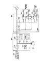
 図1は、本実施形態に係る電力制御システムの全体構成図である。以下の図面において、電力ラインは太線で示し、制御信号ラインは破線で示している。なお、制御信号ラインは有線に限らず無線であってもよい。 FIG. 1 is an overall configuration diagram of a power control system according to the present embodiment. In the following drawings, power lines are indicated by thick lines, and control signal lines are indicated by broken lines. The control signal line is not limited to wired and may be wireless.
 図1に示すように、本実施形態に係る電力制御システムは、電力会社の電力系統1からAC電力の供給を受ける需要家に、太陽電池(PV)100、蓄電池200、ガス発電装置220、パワーコンディショナ(PCS)400、分電盤500、スマートメータ600、及びHEMS700が設けられる。 As illustrated in FIG. 1, the power control system according to the present embodiment is configured to provide a solar battery (PV) 100, a storage battery 200, a gas power generation device 220, and a power supplier to a customer who receives supply of AC power from the power grid 1 of a power company. A conditioner (PCS) 400, a distribution board 500, a smart meter 600, and an HEMS 700 are provided.
 PV100は、太陽光を受けて発電し、PCS400との間に設けられた電力ラインを介して、発電により得られたDC電力(以下、PV発電電力)をPCS400に出力する。なお、PV100は、1又は複数のパネルにより構成される。また、PV100は、複数のパネルにより構成されたストリングを複数用いて構成されていてもよい。 The PV 100 receives sunlight and generates power, and outputs DC power (hereinafter, PV generated power) obtained by the power generation to the PCS 400 via a power line provided between the PV 100 and the PCS 400. The PV 100 is configured of one or more panels. In addition, the PV 100 may be configured using a plurality of strings configured by a plurality of panels.
 蓄電池200は、電力を蓄えるものであり、PCS400との間に設けられた電力ラインを介して、放電により得られたDC電力(以下、蓄電池放電電力)をPCS400に出力すると共に、PCS400からのDC電力を充電する。また、蓄電池200は、PCS400との間に設けられた制御信号ラインを介して、蓄えている電力を示す情報をPCS400に出力すると共に、充放電を行うための制御信号が入力される。 Storage battery 200 stores power, and outputs DC power obtained by discharge (hereinafter, storage battery discharged power) to PCS 400 via a power line provided between PCS 400 and DC from PCS 400. Charge the power. In addition, storage battery 200 outputs information indicating stored power to PCS 400 via a control signal line provided between PCS 400 and a control signal for performing charging and discharging.
 ガス発電装置220は、図示を省略するガスラインを介して入力される都市ガス又はプロパンガスを用いて発電を行う家庭用燃料電池である。ガス発電装置220は、PCS400との間に設けられた電力ラインを介して、発電により得られたDC電力(以下、ガス発電電力)をPCS400に出力する。本実施形態では、ガス発電装置220には、ガス発電装置220の周辺温度を計測するための温度センサ(不図示)が設けられている。ガス発電装置220は、PCS400との間に設けられた制御信号ラインを介して、発電を制御するための制御信号が入力され、温度計測値や駆動停止時間をPCS400に出力する。 The gas power generation device 220 is a household fuel cell that generates electric power using city gas or propane gas input via a gas line (not shown). The gas power generation apparatus 220 outputs DC power (hereinafter, gas generated power) obtained by the power generation to the PCS 400 via a power line provided between the gas power generation apparatus 220 and the PCS 400. In the present embodiment, the gas generator 220 is provided with a temperature sensor (not shown) for measuring the temperature around the gas generator 220. The gas power generation apparatus 220 receives a control signal for controlling power generation via a control signal line provided between the gas power generation apparatus 220 and the PCS 400, and outputs a temperature measurement value and a drive stop time to the PCS 400.
 ガス発電装置220は、ヒータや補機(各種ポンプなど)を起動するための起動電力を要する第1の発電装置に相当する。ガス発電装置220は、分電盤500との間に設けられた電力ラインを介してAC電力が入力され、入力されたAC電力が起動電力に達している場合に起動する。ヒータは、セルスタックなどの燃料電池モジュールを温めるためのバーナに着火するための着火ヒータや電気ヒータなどを含む。補機は、燃料を輸送するポンプ、ブロア、それらを制御するCPUなどを含む。 The gas power generation device 220 corresponds to a first power generation device that requires start-up power for starting a heater or an accessory (such as various pumps). The gas power generation apparatus 220 is activated when AC power is input via a power line provided between the power distribution board 500 and the input AC power reaches the startup power. The heater includes an ignition heater, an electric heater, and the like for igniting a burner for heating a fuel cell module such as a cell stack. The accessories include a pump for transporting fuel, a blower, a CPU for controlling them, and the like.
 負荷300は、分電盤500との間に設けられた電力ラインを介してAC電力が供給され、供給されたAC電力を消費して動作する。負荷300は、1つであってもよく、複数であってもよい。負荷300には、照明、あるいはエアコンや冷蔵庫、テレビ等の家電機器に限らず、蓄熱器等が含まれていることがある。また、負荷300は、HEMS700と通信可能に構成され、HEMS700からの制御コマンドに応じて省電力モードに移行するように構成される。 The load 300 is supplied with AC power via a power line provided between the distribution board 500 and operates by consuming the supplied AC power. The load 300 may be one or more than one. The load 300 may include not only lighting, but also household appliances such as an air conditioner, a refrigerator, and a television, but also a heat accumulator or the like. Further, the load 300 is configured to be communicable with the HEMS 700, and configured to shift to the power saving mode according to a control command from the HEMS 700.
 PCS400は、PV100の発電及び蓄電池200の放電により得られるDC電力をACに変換して出力する機能と、電力系統1からのAC電力をDCに変換して出力する機能とを有する。このようなPCS400は、ハイブリッドPCSと称されることがある。PCS400は、分電盤500との間に設けられた電力ラインを介して、AC電力を分電盤500と入出力する。また、PCS400は、蓄電池200との間に設けられた電力ラインを介して、蓄電池200を充電するためのDC電力を蓄電池200に出力する。 The PCS 400 has a function of converting DC power obtained by the power generation of the PV 100 and discharging of the storage battery 200 into AC and outputting it, and a function of converting AC power from the power system 1 into DC and outputting it. Such PCS 400 may be referred to as a hybrid PCS. The PCS 400 inputs / outputs AC power to / from the distribution board 500 via a power line provided between the PCS 400 and the distribution board 500. Further, PCS 400 outputs DC power for charging storage battery 200 to storage battery 200 through a power line provided between storage battery 200 and PCS 400.
 PCS400は、DC/DC変換器410、DC/AC変換器420、コントローラ430、及び自立運転用コンセント440を有する。ただし、PCS400は、自立運転用コンセント440を有していなくてもよい。 The PCS 400 has a DC / DC converter 410, a DC / AC converter 420, a controller 430, and a self-supporting outlet 440. However, the PCS 400 may not have the self-supporting outlet 440.
 DC/DC変換器410は、PV発電電力をDC/DC変換し、コントローラ430の制御下で、DC電力を蓄電池200及び/又はDC/AC変換器420に出力する。 The DC / DC converter 410 DC / DC converts the PV generated power, and outputs the DC power to the storage battery 200 and / or the DC / AC converter 420 under the control of the controller 430.
 DC/AC変換器420は、コントローラ430の制御下で、DC/DC変換器410が出力するDC電力、及び/又は、蓄電池放電電力をACに変換して分電盤500に出力する。また、自立運転用コンセント440に負荷が接続されている場合、DC/AC変換器420は、コントローラ430の制御下で、AC電力を自立運転用コンセント440に出力する。さらに、DC/AC変換器420は、コントローラ430の制御下で、分電盤500から入力されるAC電力をDCに変換して蓄電池200に出力する。 The DC / AC converter 420 converts the DC power output from the DC / DC converter 410 and / or the storage battery discharge power into AC and outputs the AC power to the distribution board 500 under the control of the controller 430. Further, when a load is connected to the stand-alone operation outlet 440, the DC / AC converter 420 outputs AC power to the stand-alone operation outlet 440 under the control of the controller 430. Further, under the control of the controller 430, the DC / AC converter 420 converts AC power input from the distribution board 500 into DC and outputs the DC to the storage battery 200.
 コントローラ430は、PCS400の各種機能を制御するものであり、CPUやメモリを用いて構成される。また、コントローラ430は、HEMS700との間で各種の制御信号を送受信する。詳細には、コントローラ430は、PV発電電力の計測値と、ガス発電電力の計測値と、蓄電池200が蓄えている電力(以下、蓄電池蓄電電力)の計測値と、自立運転用コンセント440が供給している電力の計測値とを取得し、これらの計測値をHEMS700に通知する。コントローラ430は、ガス発電装置220の発電停止を検出すると、その旨の制御信号をHEMS700に通知する。 The controller 430 controls various functions of the PCS 400, and is configured using a CPU and a memory. The controller 430 also transmits and receives various control signals to and from the HEMS 700. In detail, the controller 430 supplies the measured value of the PV generated power, the measured value of the gas generated power, the measured value of the power stored in the storage battery 200 (hereinafter, stored power of storage battery), and the outlet 440 for the independent operation The measurement values of the power being measured are acquired, and these measurement values are notified to the HEMS 700. When the controller 430 detects the power generation stop of the gas power generation device 220, the controller 430 notifies the HEMS 700 of a control signal to that effect.
 また、コントローラ430は、HEMS700から受信した制御コマンドに従って、蓄電池200の充放電を制御したり、PV発電電力を調整したりする。なお、コントローラ430には、ユーザからの入力を受け付けるユーザインターフェイス部が接続されていてもよい。 Further, controller 430 controls charging / discharging of storage battery 200 or adjusts PV generated power in accordance with the control command received from HEMS 700. The controller 430 may be connected to a user interface unit that receives an input from a user.
 自立運転用コンセント440は、自立運転中に負荷への電力供給を行うためのものである。ただし、自立運転用コンセント440は、PCS400に設けられている場合に限らず、電力ラインを介してPCS400から離間して設けられていることもある。 The self-sustaining operating outlet 440 is for supplying power to the load during self-sustaining operation. However, the outlet 440 for self-sustaining operation is not limited to the case where it is provided in the PCS 400, and may be provided separately from the PCS 400 via a power line.
 分電盤500は、PCS400のコントローラ430及び/又はHEMS700の制御下で、電力の分配を行う。分電盤500は、PCS400が出力するAC電力が負荷300の消費電力未満であるときには、不足分のAC電力を電力系統1から受電して、PCS400が出力するAC電力と電力系統1から受電したAC電力とを負荷300に供給する。また、分電盤500は、PCS400が出力するAC電力が負荷300の消費電力を超えるときには、超過分のAC電力を電力系統1に送電(売電)する。 The distribution board 500 distributes power under the control of the controller 430 and / or the HEMS 700 of the PCS 400. When the AC power output from the PCS 400 is less than the power consumption of the load 300, the distribution board 500 receives the AC power for the shortage from the power system 1 and receives the AC power output from the PCS 400 and the power system 1 AC power is supplied to the load 300. Further, when the AC power output from the PCS 400 exceeds the power consumption of the load 300, the distribution board 500 transmits (sells) the excess AC power to the power system 1.
 なお、PCS400からの電力及び電力系統1からの電力の両電力を負荷300に供給する運転状態は「連系運転」と称され、PCS400からの電力のみを負荷300に供給する運転状態は「自立運転」と称される。分電盤500は、電力系統1の停電(以下、単に「停電」という)時において、電力系統1からの解列を行って、連系運転から自立運転に移行する。 In addition, the driving | running state which supplies both the electric power from PCS400 and the electric power from power system 1 to load 300 is called "interconnected operation", and the driving state which supplies only the power from PCS400 to load 300 is "independent It is called "operation". Distribution board 500 performs disconnection from electric power system 1 at the time of a power failure of electric power system 1 (hereinafter, simply referred to as “power failure”), and shifts from the interconnection operation to the autonomous operation.
 なお、連系運転から自立運転への切り替えには、自立運転用コンセント440へ負荷300を差し替える方法と、分電盤500が自動切り替えを行う方法とがある。以下においては、分電盤500が自動切り替えを行うケースを主として説明する。 In addition, there exist a method of replacing the load 300 to the receptacle 440 for self sustaining, and the method of the power distribution panel 500 performing an automatic switch in switching from a system connection operation to a self sustaining operation. In the following, a case where the distribution board 500 performs automatic switching will be mainly described.
 自立運転時においては、負荷300には、PV発電電力及び蓄電池放電電力が、PCS400及び分電盤500を介して供給される。すなわち、本実施形態において、PV100、蓄電池200、PCS400、及び分電盤500は、負荷300に電力を供給する電力供給手段を構成する。 During self-sustaining operation, PV generated power and storage battery discharged power are supplied to load 300 via PCS 400 and distribution board 500. That is, in the present embodiment, the PV 100, the storage battery 200, the PCS 400, and the distribution board 500 constitute a power supply unit that supplies power to the load 300.
 スマートメータ600は、電力系統1と分電盤500との間の電力ライン上に設けられており、電力系統1と入出力する売電買電電力を計測し、計測値をHEMS700に通知する。また、スマートメータ600は、外部ネットワーク2との通信を行って、売電買電電力の計測値を外部ネットワーク2に送信したり、電気料金情報等を受信したりする。スマートメータ600(又はPCS400)は、停電を検出すると、その旨の制御信号をHEMS700に送信する。 The smart meter 600 is provided on the power line between the power system 1 and the distribution board 500, measures the selling and selling power to and from the power system 1, and notifies the measurement value to the HEMS 700. In addition, the smart meter 600 communicates with the external network 2 to transmit the measured value of the power sale purchase power to the external network 2 or to receive the electricity charge information and the like. When the smart meter 600 (or PCS 400) detects a power failure, it transmits a control signal to that effect to the HEMS 700.
 HEMS700は、需要家内の電力管理を行うためのものであり、PCS400や分電盤500に対して各種の制御コマンドを送信することにより需要家内の各機器を制御する機能と、各種の計測値を収集して需要家内の各機器の状態を監視・表示する機能とを有する。また、HEMS700は、負荷300の運転スケジュールを決定し、決定した運転スケジュールに従った制御を行う。本実施形態において、HEMS700は、電力供給手段(PV100、蓄電池200、PCS400等)と負荷300とを制御する制御装置に相当する。なお、HEMS700は、外部ネットワーク2との通信を行うことにより、制御に用いる情報を外部ネットワーク2から取得してもよい。 The HEMS 700 is for managing the power in the customer, and transmits various control commands to the PCS 400 and the distribution board 500 to control each device in the customer, and various measured values. It has a function to collect and monitor and display the status of each device in the customer. The HEMS 700 also determines the operation schedule of the load 300 and performs control according to the determined operation schedule. In the present embodiment, the HEMS 700 corresponds to a control device that controls the power supply unit (PV 100, storage battery 200, PCS 400, etc.) and the load 300. The HEMS 700 may acquire information used for control from the external network 2 by communicating with the external network 2.
 次に、PCS400及び分電盤500の詳細構成について説明する。図2は、PCS400及び分電盤500の詳細構成例1を示す図である。 Next, detailed configurations of the PCS 400 and the distribution board 500 will be described. FIG. 2 is a view showing a detailed configuration example 1 of the PCS 400 and the distribution board 500. As shown in FIG.
 図2に示すように、本構成例に係るPCS400は、DC/DC変換器410、DC/AC変換器420、及びコントローラ430に加え、表示部450及びスピーカ460を有する。停電時において表示部450は、コントローラ430の制御下で、停電中である旨の表示を行う。また、停電時においてスピーカ460は、コントローラ430の制御下で、停電中である旨の音声出力を行う。さらには、後述する停電予定期間の入力や負荷優先順位等の指定が可能な入力部470を備えるようにしてもよい。 As shown in FIG. 2, the PCS 400 according to this configuration example has a display unit 450 and a speaker 460 in addition to the DC / DC converter 410, the DC / AC converter 420, and the controller 430. At the time of power failure, the display unit 450 displays that power failure is under the control of the controller 430. Further, at the time of the power failure, the speaker 460 performs an audio output indicating that the power failure is in progress under the control of the controller 430. Furthermore, an input unit 470 may be provided which can input an expected power failure period, which will be described later, and can specify a load priority and the like.
 また、本構成例に係る分電盤500は、電力系統1からの解列を行う機能と、自立運転中に電力供給の有無をコンセント801~804毎に切り換える機能とを有する。詳細には、分電盤500は、サービスブレーカ501、主幹ブレーカ502、電力スイッチ503~508、及び消費電力センサCTを有する。 Further, the distribution board 500 according to this configuration example has a function of performing parallel connection from the electric power system 1 and a function of switching the presence or absence of the power supply during the independent operation for each of the outlets 801 to 804. Specifically, the distribution board 500 includes a service breaker 501, a master breaker 502, power switches 503 to 508, and a power consumption sensor CT.
 サービスブレーカ501、主幹ブレーカ502、及び電力スイッチ503~508は、PCS400のコントローラ430の制御下でオン/オフする。電力センサCTは、コンセント801乃至804に接続された負荷(例えば照明、冷蔵庫)が消費する電力を計測し、計測値をコントローラ430に通知する。 The service breaker 501, the master breaker 502, and the power switches 503 to 508 turn on / off under the control of the controller 430 of the PCS 400. The power sensor CT measures the power consumed by a load (for example, a light, a refrigerator) connected to the outlet 801 to 804, and notifies the controller 430 of the measured value.
 電力系統1から電力が得られている場合には、コントローラ430は、例えばHEMS700からの制御コマンドに応じて、サービスブレーカ501及び主幹ブレーカ502のそれぞれをオン状態にする。これにより、コンセント801~804に接続された負荷に対して電力供給可能な状態になる。 When power is obtained from the power system 1, the controller 430 turns on the service breaker 501 and the master breaker 502, for example, in response to a control command from the HEMS 700. As a result, power can be supplied to the loads connected to the outlets 801 to 804.
 これに対し、停電により自立運転に移行した場合には、コントローラ430は、例えばHEMS700からの制御コマンドに応じて、サービスブレーカ501をオン状態にしたまま、主幹ブレーカ502をオフ(解列)状態にする。これにより、これにより、コンセント801及び802に接続された負荷に対してはPCS400が出力するAC電力を供給可能な状態になるものの、コンセント803及び804に接続された負荷に対しては電力供給不能な状態になる。 On the other hand, when transitioning to a self-sustaining operation due to a power failure, for example, in response to a control command from the HEMS 700, the controller 430 puts the master breaker 502 in the OFF (disconnected) state while keeping the service breaker 501 in the ON state. Do. As a result, although the AC power output from the PCS 400 can be supplied to the loads connected to the outlets 801 and 802, the power can not be supplied to the loads connected to the outlets 803 and 804. It will be
 従って、優先順位の高い負荷をコンセント801及び802に接続することによって、自立運転中に、これら優先順位の高い負荷に対して電力を供給できる。 Thus, by connecting high priority loads to outlets 801 and 802, power can be supplied to these high priority loads during stand-alone operation.
 図3は、PCS400及び分電盤500の詳細構成例2を示す図である。 FIG. 3 is a diagram showing a detailed configuration example 2 of the PCS 400 and the distribution board 500. As shown in FIG.
 図3に示すように、本構成例に係るPCS400は、DC/DC変換器410、双方向DC/AC変換器420、及びコントローラ430を有する点は構成例1と同様であるが、電力スイッチ401及び402を有する点で構成例1とは異なる。また、本構成例に係る分電盤500は、サービスブレーカ501及び主幹ブレーカ502を有する点は構成例1と同様であるが、コントローラ520と、コンセント801~805毎に設けられた電力スイッチ511~515とを有する点で構成例1とは異なる。さらに、本構成例では、コンセント801~805毎に消費電力センサSが設けられており、コントローラ520が各計測値を収集してPCS400のコントローラ430に通知する。なお、図3ではコントローラ520と消費電力センサSとの信号線の接続を省略して図示している。 As shown in FIG. 3, the PCS 400 according to the present configuration example is the same as the configuration example 1 in that the DC / DC converter 410, the bidirectional DC / AC converter 420, and the controller 430 are included. And 402 are different from the first configuration example. Further, the distribution board 500 according to this configuration example is the same as the configuration example 1 in that the service breaker 501 and the master breaker 502 are included, but the controller 520 and the power switch 511 provided for each of the outlets 801 to 805 The fifth embodiment differs from the first configuration example in having 515. Furthermore, in the present configuration example, the power consumption sensor S is provided for each of the outlets 801 to 805, and the controller 520 collects each measured value and notifies the controller 430 of the PCS 400. In FIG. 3, connection of signal lines between the controller 520 and the power consumption sensor S is omitted.
 電力系統1から電力が得られている場合には、コントローラ430は、例えばHEMS700からの制御コマンドに応じて、電力スイッチ401、サービスブレーカ501、及び主幹ブレーカ502のそれぞれをオン状態にし、電力スイッチ402をオフ状態にするよう制御し、電力スイッチ511~515のそれぞれを電力系統1側に切り換えるよう制御する。これにより、コンセント801~805に接続された負荷に対して電力供給可能な状態になる。 When power is obtained from the power system 1, the controller 430 turns on each of the power switch 401, the service breaker 501, and the master breaker 502 in response to a control command from the HEMS 700, for example, and the power switch 402. Of the power switches 511 to 515 are controlled to be switched to the power system 1 side. As a result, power can be supplied to the loads connected to the outlets 801 to 805.
 これに対し、停電により自立運転に移行した場合には、コントローラ430は、例えばHEMS700からの制御コマンドに応じて、電力スイッチ401、サービスブレーカ501、及び主幹ブレーカ502をオフ状態にし、電力スイッチ402をオン状態にするよう制御する。本実施の形態のように電力スイッチ401、402をPCS400内に持つことにより、自立運転時の負荷への電力制御をPCS400内で行うことができるようになる。 On the other hand, when transitioning to a self-sustaining operation due to a power failure, the controller 430 turns off the power switch 401, the service breaker 501, and the master breaker 502 in response to a control command from the HEMS 700, for example. Control to turn on. By having the power switches 401 and 402 in the PCS 400 as in the present embodiment, power control to the load during stand-alone operation can be performed in the PCS 400.
 また、コントローラ520は、例えばコントローラ430からの指示に応じて、図3の下方に示すように電力スイッチ511~515を順次(循環的に)オン状態に切り換えるよう制御する。すなわち、コンセント801~805において、電力供給可能とする時間を順次(循環的に)割り当てるよう制御する。これにより、コンセント801~805毎に接続された複数の負荷において、2つ以上の負荷に対して同時に電力が供給されることが防止されるため、消費電力を時間的に分散させる(平準化させる)ことができる。以下においては、このような制御を「電力平準化制御」と称する。なお、割り当てる時間間隔は、数分から数十分単位であればよく、継続して電力供給が必要な負荷は継続的に供給するようにすればよい。 Further, in response to an instruction from the controller 430, for example, the controller 520 controls the power switches 511 to 515 to be sequentially (circularly) switched on as shown in the lower part of FIG. That is, in the outlets 801 to 805, control is performed so as to sequentially (circularly) allocate time for which power can be supplied. As a result, it is prevented that power is simultaneously supplied to two or more loads at a plurality of loads connected to each of the outlets 801 to 805, so that the power consumption is dispersed temporally (evening) )be able to. Hereinafter, such control is referred to as “power leveling control”. Note that the time interval to be assigned may be from several minutes to several tens of minutes, and the load requiring the power supply may be continuously supplied.
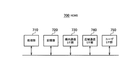
 次に、HEMS700の詳細構成について説明する。図4は、HEMS700の構成図である。 Next, the detailed configuration of the HEMS 700 will be described. FIG. 4 is a block diagram of the HEMS 700. As shown in FIG.
 図4に示すように、HEMS700は、処理部710、記憶部720、構内通信I/F部730、広域通信I/F部740、及びユーザI/F部750を有する。処理部710、記憶部720、構内通信I/F部730、広域通信I/F部740、及びユーザI/F部750は、バスライン又はLANを介して情報をやり取りする。 As shown in FIG. 4, the HEMS 700 includes a processing unit 710, a storage unit 720, a local communication I / F unit 730, a wide area communication I / F unit 740, and a user I / F unit 750. The processing unit 710, the storage unit 720, the local communication I / F unit 730, the wide area communication I / F unit 740, and the user I / F unit 750 exchange information via a bus line or a LAN.
 処理部710は、例えばCPUにより構成されており、記憶部720に記憶されている制御プログラムを実行することで、HEMS700の各種機能を制御する。また、処理部710は、後述する自立運転制御を行う。処理部710の機能ブロック構成については後述する。 The processing unit 710 includes, for example, a CPU, and controls various functions of the HEMS 700 by executing a control program stored in the storage unit 720. Moreover, the processing unit 710 performs a self-sustaining operation control described later. The functional block configuration of the processing unit 710 will be described later.
 記憶部720は、例えばRAMや不揮発メモリにより構成されており、HEMS700の制御等に用いられる各種の情報を記憶する。 The storage unit 720 includes, for example, a RAM and a non-volatile memory, and stores various types of information used for control of the HEMS 700 and the like.
 構内通信I/F部730は、需要家内の各機器との通信を行うための通信I/Fである。構内通信I/F部730は、例えばZigbee(登録商標)又はイーサネット(登録商標)等による通信を行う。 The local communication I / F unit 730 is a communication I / F for performing communication with each device in the customer. The local communication I / F unit 730 performs communication by, for example, Zigbee (registered trademark) or Ethernet (registered trademark).
 広域通信I/F部740は、外部ネットワーク2との通信を行うための通信I/Fである。 The wide area communication I / F unit 740 is a communication I / F for communicating with the external network 2.
 ユーザI/F部750は、ユーザからの入力を受け付ける入力部や、各種の表示を行う表示部を含んで構成されている。 The user I / F unit 750 includes an input unit that receives an input from the user and a display unit that performs various displays.
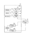
 図5は、処理部710の機能ブロック図である。 FIG. 5 is a functional block diagram of the processing unit 710. As shown in FIG.
 図5に示すように、処理部710は、電力検出部711A、温度検出部711B、停電・停止検出部711C、制御コマンド生成部712、情報取得部713、運転スケジュール決定部714A、及び運転スケジュール変更部714Bを有する。 As shown in FIG. 5, the processing unit 710 includes a power detection unit 711A, a temperature detection unit 711B, a power failure / stop detection unit 711C, a control command generation unit 712, an information acquisition unit 713, an operation schedule determination unit 714A, and an operation schedule change. It has part 714B.
 電力検出部711Aは、PCS400から構内通信I/F部730が受信する各計測値のうち、PV発電電力の計測値及び蓄電池蓄電電力の計測値を合計した結果を、停電開始時に負荷300に供給可能な電力(以下、停電開始時供給電力)として検出して制御コマンド生成部712に出力する。 Among the measured values received by the indoor communication I / F unit 730 from the PCS 400, the power detection unit 711A supplies the load 300 with the result of the sum of the measured value of the PV generated power and the measured value of the storage power of the storage battery. It is detected as possible power (hereinafter, power supply at the start of a power failure) and is output to the control command generation unit 712.
 温度検出部711Bは、PCS400から構内通信I/F部730が受信する各計測値のうち、ガス発電装置220の周辺温度の計測値を検出して制御コマンド生成部712に出力する。 The temperature detection unit 711 B detects the measurement value of the ambient temperature of the gas power generation device 220 among the measurement values received by the indoor communication I / F unit 730 from the PCS 400, and outputs the measurement value to the control command generation unit 712.
 停電・停止検出部711Cは、スマートメータ600(又はPCS400)から構内通信I/F部730が受信する停電通知を検出して制御コマンド生成部712に出力する。あるいは、停電・停止検出部711Cは、外部ネットワーク2から広域通信I/F部740が受信する停電通知を検出して制御コマンド生成部712に出力してもよい。 The power failure / stop detection unit 711 C detects a power failure notification received by the local communication I / F unit 730 from the smart meter 600 (or the PCS 400), and outputs the notification to the control command generation unit 712. Alternatively, the power failure / stop detection unit 711C may detect a power failure notification received by the wide area communication I / F unit 740 from the external network 2 and output the notification to the control command generation unit 712.
 また、停電・停止検出部711Cは、PCS400から広域通信I/F部740が受信するガス発電停止通知を検出して制御コマンド生成部712に出力する。その際らに、ガス発電装置220の停止時間を検出して制御コマンド生成部712に出力するようにしてもよい。 Further, the power failure / stop detection unit 711 C detects a gas power generation stop notification received by the wide area communication I / F unit 740 from the PCS 400, and outputs the gas power generation stop notification to the control command generation unit 712. At that time, the stop time of the gas power generation device 220 may be detected and output to the control command generation unit 712.
 制御コマンド生成部712は、需要家内の各機器を制御するための制御コマンドを生成し、生成した制御コマンドを、構内通信I/F部730を介して需要家内の対象機器に送信する。 The control command generation unit 712 generates a control command for controlling each device in the customer, and transmits the generated control command to a target device in the customer via the local communication I / F unit 730.
 制御コマンド生成部712は、制御部712A、省電力制御部712B、及び電力平準化制御部712Cを有する。 The control command generation unit 712 includes a control unit 712A, a power saving control unit 712B, and a power leveling control unit 712C.
 制御部712Aは、制御部712Aは、ガス発電装置220の周辺温度またはガス発電装置220の停止時間に基づいてガス発電装置220の起動電力(標準値)を補正する。ガス発電装置220の起動電力の標準値は、記憶部720に予め格納されているものとする。また、記憶部720には、温度毎または停止時間毎の起動電力補正値が予め格納されており、制御部712Aは、ガス発電装置220の周辺温度または停止時間に対応する補正値により、起動電力の標準値を補正する。そして、制御部712Aは、以下の処理において、補正後の起動電力を用いる。 Control unit 712A corrects the startup power (standard value) of gas power generation device 220 based on the ambient temperature of gas power generation device 220 or the stop time of gas power generation device 220. It is assumed that the standard value of the start power of the gas power generation device 220 is stored in advance in the storage unit 720. In addition, the storage unit 720 stores in advance a start power correction value for each temperature or stop time, and the control unit 712A uses the correction value corresponding to the ambient temperature or stop time of the gas power generation apparatus 220 to start the power. Correct the standard value of. Then, control unit 712A uses the corrected startup power in the following processing.
 制御部712Aは、停電開始時供給電力がガス発電装置220の起動電力を下回らないように、蓄電池200の充放電を制御する制御コマンドを生成し、当該制御コマンドを広域通信I/F部740を介してPCS400に送信する。 Control unit 712A generates a control command for controlling the charge and discharge of storage battery 200 so that the supplied power at the start of a power failure does not fall below the start-up power of gas power generation apparatus 220, and transmits the control command to wide area communication I / F unit 740. It transmits to PCS400 via.
 制御部712Aは、停電が検出された場合で、停電開始時供給電力がガス発電装置220の起動電力に満たない場合に、停電開始時供給電力がガス発電装置220の起動電力を満たすように、PV100の発電により得られた電力を優先的に蓄電池200に充電するよう制御する。 When a power failure is detected and the supplied power at the start of the power failure is less than the start power of the gas generator 220, the controller 712A is configured such that the supplied power at the start of the power failure meets the start power of the gas generator 220; Control is performed to preferentially charge the storage battery 200 with the power obtained by the power generation of the PV 100.
 制御部712Aは、停電が検出された場合で、ガス発電装置220が発電を停止している場合に、停電開始時供給電力、すなわち、PV発電電力及び蓄電電力を優先的にガス発電装置220に供給するよう制御する制御コマンドを生成し、当該制御コマンドを構内通信I/F部730を介してPCS400及び分電盤500に送信する。 When a power failure is detected, and the gas power generation device 220 stops power generation, the control unit 712A gives priority to the gas power generation device 220 at the power failure start supply power, that is, the PV generated power and the stored power. A control command for controlling supply is generated, and the control command is transmitted to the PCS 400 and the distribution board 500 via the local communication I / F unit 730.
 省電力制御部712Bは、自立運転開始時において、負荷300を省電力モードで動作させる「省電力制御」を指示するための省電力制御コマンドを生成し、生成した省電力制御コマンドを、構内通信I/F部730を介して負荷300に送信する。 The power saving control unit 712B generates a power saving control command for instructing “power saving control” to operate the load 300 in the power saving mode at the start of the stand-alone operation, and generates the power saving control command for local communication It transmits to the load 300 via the I / F unit 730.
 電力平準化制御部712Cは、自立運転開始時において、上述した電力平準化制御を指示するための電力平準化制御コマンドを生成し、生成した電力平準化制御コマンドを、構内通信I/F部730を介して分電盤500に送信する。 The power leveling control unit 712 C generates a power leveling control command for instructing the above-described power leveling control at the start of the stand-alone operation, and the generated power leveling control command is transmitted to the indoor communication I / F unit 730. To the distribution board 500.
 情報取得部713は、構内通信I/F部730及び/又は広域通信I/F部740を介して、自立運転中の負荷300の運転スケジュールである自立運転中スケジュールを決定するための各種の情報(詳細については後述)を取得する。 The information acquisition unit 713 is a variety of information for determining a schedule during autonomous operation which is an operation schedule of the load 300 during autonomous operation through the local communication I / F unit 730 and / or the wide area communication I / F unit 740. Acquire (details will be described later).
 運転スケジュール決定部714Aは、情報取得部713によって取得された情報に基づいて自立運転中スケジュールを決定する。運転スケジュール決定部714Aは、決定した自立運転中スケジュールの情報を、記憶部720に設けられた運転スケジュール記憶部721に格納する。 The driving schedule determination unit 714A determines the autonomous driving schedule based on the information acquired by the information acquisition unit 713. Driving schedule determination unit 714 </ b> A stores the information on the determined autonomous driving schedule in driving schedule storage unit 721 provided in storage unit 720.
 運転スケジュール変更部714Bは、情報取得部713によって新たに取得された情報に基づいて、運転スケジュール記憶部721に格納されている自立運転中スケジュールを変更し、変更後の運転スケジュールによって変更前の運転スケジュールを更新する。 Based on the information newly acquired by the information acquisition unit 713, the operation schedule change unit 714B changes the autonomous driving schedule stored in the operation schedule storage unit 721, and the operation before the change is performed according to the changed operation schedule. Update the schedule.
 制御コマンド生成部712は、運転スケジュール記憶部721に格納されている運転スケジュールに従って制御コマンドを生成し、生成した制御コマンドを、構内通信I/F部730を介して需要家内の対象機器に送信する。 Control command generation unit 712 generates a control command according to the operation schedule stored in operation schedule storage unit 721, and transmits the generated control command to the target device in the customer via local communication I / F unit 730. .
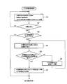
 次に、HEMS700によるガス発電起動制御フローを説明する。図6は、HEMS700によるガス発電起動制御フローのフローチャートである。 Next, a gas power generation start control flow by the HEMS 700 will be described. FIG. 6 is a flowchart of a gas power generation start control flow by the HEMS 700.
 図6に示すように、ステップS1において、電力検出部711Aは、PV発電電力の計測値及び蓄電池蓄電電力の計測値を合計した結果を停電開始時供給電力として検出する。また、温度検出部711Bは、ガス発電装置220の周辺温度の計測値を検出する、または停電・停止検出部711Cは、ガス発電装置220の停止時間を検出する。この周辺温度の計測値または停止時間を検出することにより、ガス発電装置220の現状の温度を把握でき、起動電力として必要となる最適電力を予測することができるようになる。具体的には、最初の温度が低い、または停止時間が長い場合は、ガス発電装置220が起動してから所定の温度に到達するまでに時間を要するため、トータルの起動電力量が大きくなる。以下では、このように変化する起動電力量を「起動電力補正」として説明する。 As shown in FIG. 6, in step S1, the power detection unit 711A detects the result of the sum of the measured value of the PV generated power and the measured value of the storage power of the storage battery as the power supply at the start of a power failure. In addition, the temperature detection unit 711B detects a measurement value of the temperature around the gas power generation device 220, or the power failure / stop detection unit 711C detects the stop time of the gas power generation device 220. By detecting the measured value of the ambient temperature or the stop time, it is possible to grasp the current temperature of the gas power generation device 220 and to predict the optimum power necessary for the start power. Specifically, when the initial temperature is low or the stop time is long, it takes time to reach a predetermined temperature after the gas power generation device 220 is started, and thus the total amount of start power becomes large. Hereinafter, the amount of starting power changing in this manner will be described as “starting power correction”.
 制御部712Aは、ガス発電装置220の起動電力の温度補正を行った後、停電開始時供給電力が補正後の起動電力を満たすように制御コマンドを生成する。例えば、制御部712Aは、停電開始時供給電力が補正後の起動電力に満たない場合には、蓄電電力を増加させる制御コマンドを生成して送信する。 After performing the temperature correction of the activation power of the gas power generation device 220, the control unit 712A generates a control command so that the power supply at the start of a power failure satisfies the corrected activation power. For example, when the power supply at the start of power failure does not reach the post-correction starting power, the control unit 712A generates and transmits a control command to increase stored power.
 ステップS2において停電・停止検出部711Cが停電の発生を検出した場合(ステップS2;YES)で、かつ、ステップS3において停電・停止検出部711Cがガス発電装置220の発電停止を検出した場合、処理がステップS4に進む。停電の発生を検出しない場合(ステップS2;NO)には、処理がステップS1に戻る。停電・停止検出部711Cが停電の発生を検出した場合(ステップS2;YES)で、かつ、ステップS3において停電・停止検出部711Cがガス発電装置220の発電停止を検出しない場合、処理が自立運転制御フロー(詳細については後述)に進む。 If the power failure / stop detection unit 711 C detects the occurrence of a power failure in step S 2 (step S 2; YES), and if the power failure / stop detection unit 711 C detects the power generation stop of the gas power generation apparatus 220 in step S 3, processing The process proceeds to step S4. If the occurrence of a power failure is not detected (step S2; NO), the process returns to step S1. If the power failure / stop detection unit 711 C detects the occurrence of a power failure (step S 2; YES), and the power failure / stop detection unit 711 C does not detect the power generation stop of the gas power generation apparatus 220 in step S 3, the process is a self-sustaining operation. Control flow (details will be described later).
 ステップS4において、電力検出部711Aは、PV発電電力の計測値及び蓄電池蓄電電力の計測値を合計した結果を停電開始時供給電力として検出する。また、温度検出部711Bは、ガス発電装置220の周辺温度の計測値を検出する。そして、制御部712Aは、ガス発電装置220の起動電力の温度補正を行う。 In step S4, the power detection unit 711A detects the result of adding up the measured value of the PV generated power and the measured value of the storage power of the storage battery as the power supply at the start of a power failure. In addition, the temperature detection unit 711 B detects a measurement value of the temperature around the gas power generation device 220. Then, the control unit 712A performs temperature correction of the activation power of the gas power generation device 220.
 ステップS5において制御部712Aが停電開始時供給電力が補正後の起動電力を満たさないと判定した場合(ステップS5;NO)、ステップS6において、制御部712Aは、PV発電電力を蓄電池200に蓄電するよう制御する制御コマンドを生成してPCS400に送信する。その後、ステップS4に処理が戻る。 If controller 712A determines in step S5 that the power supply at the start of a power failure does not satisfy the corrected startup power (step S5; NO), controller 712A stores the PV generated power in storage battery 200 in step S6. Control command to be generated and sent to the PCS 400. Thereafter, the process returns to step S4.
 これに対し、ステップS5において制御部712Aが停電開始時供給電力が補正後の起動電力を満たすと判定した場合(ステップS5;YES)、ステップS7において、制御部712Aは、停電開始時供給電力(PV発電電力及び蓄電電力)をガス発電装置220に供給するよう制御する制御コマンドを生成してPCS400及び分電盤500に送信する。その結果、ガス発電装置220が起動する。その後、処理が自立運転制御フローに進む。 On the other hand, when control unit 712A determines that the power supply at power failure start satisfies the startup power after correction at step S5 (step S5; YES), at step S7, controller 712A supplies power at power failure start ( A control command for controlling supply of the PV generated power and the stored power to the gas generator 220 is generated and transmitted to the PCS 400 and the distribution board 500. As a result, the gas generator 220 is activated. Thereafter, the process proceeds to the autonomous operation control flow.
 次に、HEMS700による自立運転制御フローを説明する。図7は、HEMS700による自立運転制御フローのフローチャートである。 Next, the control flow of the autonomous operation by the HEMS 700 will be described. FIG. 7 is a flowchart of the autonomous operation control flow by the HEMS 700.
 図7に示すように、ステップS11において、情報取得部713は、停電予定期間情報、蓄電情報、発電情報、及び消費電力情報を取得する。 As shown in FIG. 7, in step S11, the information acquisition unit 713 acquires planned power outage period information, power storage information, power generation information, and power consumption information.
 停電予定期間情報は、計画停電(輪番停電)により定められた停電予定期間を示す情報であり、例えば停電予定期間に該当する日付と、当該停電予定期間の開始時刻と、当該停電予定期間の終了時刻とを含む。情報取得部713は、広域通信I/F部740を介して外部ネットワーク2から停電予定期間情報を取得する、又は、ユーザI/F部750に対するユーザ入力に基づいて停電予定期間情報を取得する。あるいは、PCS400にユーザI/F部(例えば、図2で示す入力部470)が設けられている場合には、PCS400のユーザI/F部750に対するユーザ入力に基づいて停電予定期間情報を取得してもよい。スマートメータ600が外部ネットワーク2から停電予定期間情報を取得できる場合には、構内通信I/F部730を介してスマートメータ600から停電予定期間情報を取得してもよい。 The blackout scheduled period information is information indicating a blackout scheduled period defined by the planned blackout (rotational blackout), for example, a date corresponding to the blackout scheduled period, a start time of the blackout scheduled period, and an end of the blackout scheduled period And time. Information acquisition unit 713 acquires planned power outage period information from external network 2 via wide area communication I / F portion 740, or acquires planned power outage period information based on a user input to user I / F portion 750. Alternatively, if the PCS 400 is provided with a user I / F unit (for example, the input unit 470 shown in FIG. 2), power failure scheduled period information is acquired based on the user input to the user I / F unit 750 of the PCS 400. May be If the smart meter 600 can acquire the power outage scheduled period information from the external network 2, the power outage planned period information may be acquired from the smart meter 600 via the local communication I / F unit 730.
 本実施形態において、上述した停電予定期間情報によって示される停電予定期間は、自立運転を実行する期間に相当する。 In the present embodiment, the power failure scheduled period indicated by the above-described power failure scheduled period information corresponds to a period in which the autonomous operation is performed.
 蓄電情報は、停電前(停電直前)の蓄電池200の蓄電電力を示す情報である。情報取得部713は、構内通信I/F部730を介してPCS400から蓄電情報を取得する。 The storage information is information indicating the storage power of the storage battery 200 before the power failure (immediately before the power failure). Information acquisition unit 713 acquires power storage information from PCS 400 via local communication I / F unit 730.
 発電情報は、停電前(停電直前)のPV100及びガス発電装置220のそれぞれの発電電力を示す情報である。情報取得部713は、構内通信I/F部730を介してPCS400から発電情報を取得する。あるいは、情報取得部713は、将来の(自立運転中の)PV100の予想発電電力を得るために有益な情報に基づいて、自立運転中のPV100の予想発電電力を示す発電電力を取得する。ここで、予想発電電力を得るために有益な情報とは、例えば以下の情報である。 The power generation information is information indicating the generated power of each of the PV 100 and the gas power generator 220 before the power failure (immediately before the power failure). The information acquisition unit 713 acquires power generation information from the PCS 400 via the local communication I / F unit 730. Alternatively, the information acquisition unit 713 acquires the generated power indicating the predicted generated power of the PV 100 in the autonomous operation based on the information useful for obtaining the predicted generated power of the PV 100 in the future (during the autonomous operation). Here, the information useful for obtaining the expected generated power is, for example, the following information.
 ・天候予測や気象センサ:これらの情報から、PV100の発電に影響を与える日射量等を推定し、今後の発電電力を予測できる。情報取得部713は、天候予測情報や気象センサ情報を広域通信I/F部740を介して外部ネットワーク2から取得する。 -Weather prediction and weather sensor: From these information, it is possible to estimate the amount of solar radiation that affects the power generation of the PV 100 and predict the future generated power. The information acquisition unit 713 acquires weather prediction information and weather sensor information from the external network 2 via the wide area communication I / F unit 740.
 ・時計やカレンダ機能:これらの情報から、PV100の発電に影響を与える日射量等を推定し、今後の発電電力を予測できる。情報取得部713は、当日の日付及び現在時刻の情報を、HEMS700の内部タイマ、又は広域通信I/F部740を介して外部ネットワーク2から取得する。 -Clock and calendar functions: From these information, it is possible to estimate the amount of solar radiation that affects the power generation of the PV 100, and to predict the future generated power. The information acquisition unit 713 acquires information on the date and the current time of the day from the external network 2 via the internal timer of the HEMS 700 or the wide area communication I / F unit 740.
 ・停電開始時の発電量からの推測:例えば、停電開始時(自立運転への移行時)における発電電力が増加傾向であるか減少傾向であるかに応じて、今後の発電電力を予測できる。 Estimation from the amount of power generation at the start of a power failure: For example, it is possible to predict future power generation according to whether the power generation at the start of a power failure (at the transition to a self-sustaining operation) is increasing or decreasing.
 ・過去の発電実績データ:例えば、記憶部720に発電電力を環境条件別に格納しておき、現在の環境条件に合致する過去の発電電力を検索することによって、今後の発電電力を予測できる。 Past power generation result data: For example, by storing the generated power in the storage unit 720 for each environmental condition and searching for the generated power in the past that matches the current environmental conditions, it is possible to predict future generated power.
 本実施形態において、上述した蓄電情報及び発電情報は、電力供給手段の電力供給状況に相当する。 In the present embodiment, the storage information and the power generation information described above correspond to the power supply status of the power supply unit.
 消費電力情報は、停電前(停電直前)の負荷300の総消費電力を示す情報である。負荷300の総消費電力は例えば分電盤500で計測、又は負荷300が接続されるコンセントで計測可能であり、情報取得部713は、構内通信I/F部730を介して消費電力情報を取得する。あるいは、図2に示したように、自立運転中に電力供給を行うべき負荷が限定されている場合には、当該負荷についての消費電力情報を取得すればよい。また、自立運転用コンセント440に負荷を接続して自立運転を行う場合には、当該負荷の情報を手動又は自動で取得し、取得した情報から当該負荷についての消費電力情報を求めてもよい。 The power consumption information is information indicating the total power consumption of the load 300 before the power failure (immediately before the power failure). The total power consumption of the load 300 can be measured by, for example, the distribution board 500, or can be measured by the outlet to which the load 300 is connected, and the information acquisition unit 713 acquires power consumption information via the local communication I / F unit 730. Do. Alternatively, as shown in FIG. 2, when the load to which power is to be supplied during autonomous operation is limited, power consumption information on the load may be acquired. Moreover, when connecting a load to the outlet 440 for self-sustaining operation and performing self-sustaining operation, the information of the said load may be acquired manually or automatically, and the power consumption information about the said load may be calculated | required from the acquired information.
 基本的には、上述した停電予定期間情報、蓄電情報、発電情報、及び消費電力情報を用いることによって、自立運転中スケジュールを決定可能である。例えば、停電中(自立運転中)に負荷300に対して供給可能な総電力により、負荷300の総消費電力をどの程度賄うことができるかを判定し、停電予定期間(自立運転期間)においてどのようなタイミングで負荷300に電力を供給するかといったスケジュールが決定される。 Basically, it is possible to determine a schedule during self-sustaining operation by using the above-described power cut estimated period information, power storage information, power generation information, and power consumption information. For example, it is determined how much the total power consumption of the load 300 can be covered by the total power that can be supplied to the load 300 during a power failure (during independent operation), and in the scheduled power failure period (independent operation period) The schedule as to whether to supply power to the load 300 at such timing is determined.
 さらに、情報取得部713は、負荷優先順位情報、省電力モード情報、電力平準化情報、及び起動電力情報を取得することによって、より適切に自立運転中スケジュールを決定可能になる。 Furthermore, the information acquisition unit 713 can more appropriately determine the autonomous driving schedule by acquiring the load priority information, the power saving mode information, the power leveling information, and the startup power information.
 負荷優先順位情報は、負荷300に対する電力供給優先順位を設定した情報である。情報取得部713は、ユーザI/F部750に対するユーザ入力に基づいて負荷優先順位情報を取得する。あるいは、予め定められた優先順位での負荷優先順位情報を記憶部720に記憶しておき、記憶部720から負荷優先順位情報を取得してもよい。例えば、HEMS700や非常灯を高い優先順位に設定する。 The load priority information is information in which the power supply priority for the load 300 is set. The information acquisition unit 713 acquires load priority information based on a user input to the user I / F unit 750. Alternatively, load priority order information in a predetermined priority order may be stored in the storage unit 720, and the load priority order information may be acquired from the storage unit 720. For example, HEMS 700 and emergency lights are set to a high priority.
 省電力モード情報は、負荷300毎の省電力モードの情報(例えば、省電力モードの種類や省電力モードでの消費電力)を示す情報である。 The power saving mode information is information indicating power saving mode information for each load 300 (for example, the type of power saving mode and power consumption in the power saving mode).
 電力平準化情報は、図3に示したような電力平準化制御に関する情報(例えば、電力平準化制御の対象とすべき負荷300の情報)である。 The power leveling information is information related to power leveling control as shown in FIG. 3 (for example, information on the load 300 to be a target of power leveling control).
 起動電力情報は、負荷300毎の起動電力を示す情報である。例えば、停電時に、省電力モードとしての断続運転などを行って冷蔵庫の温度が上がったあと、電気が復旧した際にまた元の温度まで冷やし直すための起動電力は大きくなるため、連続運転を長時間続けていたほうが消費電力は少ないようなケースが想定される。よって、起動電力情報(取得可能であれば冷蔵庫の内部温度なども)を考慮してスケジュール決定を行うことが好ましい。 The startup power information is information indicating startup power for each load 300. For example, after power outage mode, intermittent operation as a power saving mode is performed to raise the temperature of the refrigerator, and when the electricity is restored, the start power for cooling back to the original temperature is also large. It is assumed that power consumption is lower if time is continued. Therefore, it is preferable to determine the schedule in consideration of the startup power information (also the internal temperature of the refrigerator if it can be acquired).
 ステップS12において、運転スケジュール決定部714Aは、情報取得部713によって取得された停電予定期間情報、蓄電情報、発電情報、消費電力情報、負荷優先順位情報、省電力モード情報、電力平準化情報、及び起動電力情報に基づいて、自立運転中スケジュールを決定する。例えば、停電中(自立運転中)に負荷300に対して供給可能な総電力により、省電力制御や電力平準化制御が加味された負荷総消費電力をどの程度賄うことができるかを判定し、負荷300の優先順位や起動電力も考慮して、停電予定期間(自立運転期間)においてどのようなタイミングでどの負荷に電力を供給するかといったスケジュールが決定される。 In step S12, the operation schedule determination unit 714A determines the power outage scheduled period information acquired by the information acquisition unit 713, power storage information, power generation information, power consumption information, load priority information, power saving mode information, power leveling information, and Based on the startup power information, a schedule during autonomous operation is determined. For example, based on the total power that can be supplied to the load 300 during a power failure (during independent operation), it is determined how much the total load power consumption including power saving control and power leveling control can be covered, In consideration of the priority of the load 300 and the starting power, a schedule is determined as to which load to which power is to be supplied at what timing in the scheduled power failure period (independent operation period).
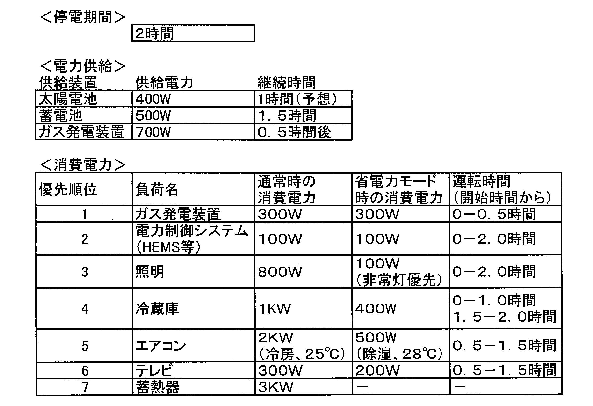
 具体例として、停電予定期間2時間と入力した後、蓄電情報と発電情報をもとに決定される負荷の自立運転スケジュールを表1に示す。このように、蓄電池と太陽電池の発電量をガス発電装置の起動電力量と負荷消費電力量の総和が超えないようにスケジュールを組めばよい。なお、30分単位で切替を行う際、図3で説明した「電力平準化制御」を行うようにしてもよい。 As a specific example, Table 1 shows a self-sustaining operation schedule of the load determined based on the storage information and the power generation information after inputting a planned power failure period of 2 hours. As described above, a schedule may be set up so that the sum of the power consumption of the gas power generating apparatus and the power consumption of the gas power generation apparatus does not exceed the amount of power generation of the storage battery and the solar cell. When switching is performed in units of 30 minutes, the “power leveling control” described in FIG. 3 may be performed.
Figure JPOXMLDOC01-appb-T000001
 運転スケジュール記憶部721は、運転スケジュール記憶部721によって決定された自立運転中スケジュールを記憶する。 The driving schedule storage unit 721 stores the autonomous driving schedule determined by the driving schedule storage unit 721.
 ステップS13において、制御コマンド生成部712は、自立運転への切り替えコマンドを生成し、生成した切り替えコマンドを、構内通信I/F部730を介してPCS400及び分電盤500に送信する。あるいは、分電盤500が自立運転への切り替えを自動で行ってもよく、ユーザが自立運転用コンセント440へ負荷300を接続することにより自立運転への切り替えを手動で行ってもよい。 In step S13, the control command generation unit 712 generates a switching command to the stand-alone operation, and transmits the generated switching command to the PCS 400 and the distribution board 500 via the local communication I / F unit 730. Alternatively, the distribution board 500 may automatically switch to the stand-alone operation, or the user may manually switch to the stand-alone operation by connecting the load 300 to the stand-alone operation outlet 440.
 ステップS14において、制御コマンド生成部712は、運転スケジュール記憶部721に記憶されている自立運転中スケジュール情報に従った制御コマンドを、構内通信I/F部730を介して、負荷300や、PCS400、分電盤500に送信する。 In step S14, the control command generation unit 712 causes the control command according to the schedule information during stand-alone operation stored in the operation schedule storage unit 721 to be transmitted to the load 300, PCS 400, or the like via the indoor communication I / F unit 730. Transmit to distribution board 500.
 停電予定期間の経過により、自立運転を終了する場合には、系統連系に切り替わり(ステップS19)、本フローが終了する。これに対し、自立運転を継続する場合(ステップS15;NO)、ステップS16において、情報取得部713は、蓄電情報、発電情報、及び負荷優先順位情報を再度取得する。蓄電情報及び発電情報を再度取得するのは、当初の予想に対して現在の蓄電電力及び現在の発電電力の誤差がある場合に、自立運転中スケジュールを変更するためである。負荷優先順位情報を再度取得するのは、携帯電話の充電が必要となった場合など、スケジュールされていない負荷の割り込みを許容するためである。また、情報取得部713は、需要家内に人感センサが設けられている場合には、人感センサ情報を取得してもよい。例えば、部屋毎に人感センサを設けておき、その部屋にユーザが居る/居ないに応じて照明やエアコン等の運転スケジュールを変更することが考えられる。 When self-sustaining operation is ended due to the elapse of the power outage scheduled period, the system is switched to grid connection (step S19), and the present flow ends. On the other hand, when the self-sustained operation is continued (step S15; NO), the information acquisition unit 713 reacquires power storage information, power generation information, and load priority order information in step S16. The storage information and the power generation information are acquired again in order to change the schedule during the autonomous operation when there is an error between the current storage power and the current generation power with respect to the initial expectation. The load priority information is acquired again in order to allow interruption of unscheduled load, for example, when the mobile phone needs to be charged. In addition, the information acquisition unit 713 may acquire human sensor information when the human sensor is provided in the consumer. For example, it is conceivable to provide a human sensor in each room, and change the operation schedule of the lighting, the air conditioner, and the like according to whether or not the user is present in the room.
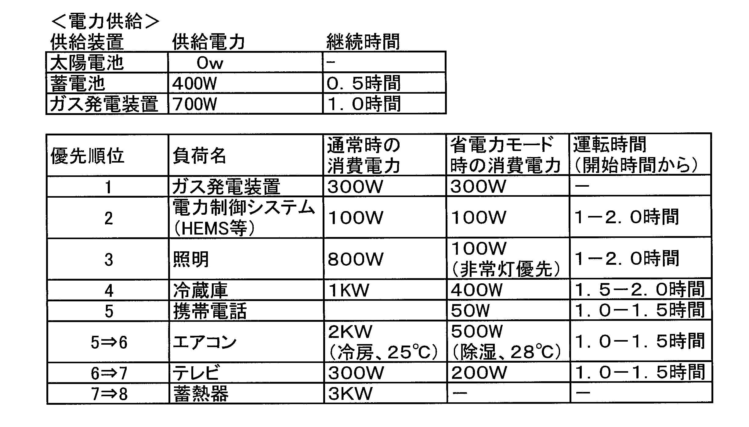
 具体例として、表1の自立運転スケジュールにて稼動後、1時間を経過した際、改めて発電情報を入手し、急遽携帯電話の充電がされた場合の自立運転スケジュールの変更を表2に示す。 As a specific example, when one hour has passed after operation according to the independent driving schedule in Table 1, power generation information is obtained again, and changes in the autonomous driving schedule when the mobile phone is charged suddenly are shown in Table 2.
Figure JPOXMLDOC01-appb-T000002
 ステップS17において、運転スケジュール変更部714Bは、情報取得部713によって取得された蓄電情報、発電情報、負荷優先順位情報、及び人感センサ情報に基づき、運転スケジュール記憶部721に格納されている自立運転中スケジュールを変更するか否かを判定する。 In step S17, the driving schedule changing unit 714B performs the autonomous driving stored in the driving schedule storage unit 721 based on the power storage information, the power generation information, the load priority order information, and the human detection sensor information acquired by the information acquiring unit 713. Medium Determine whether to change the schedule.
 自立運転中スケジュールを変更しないと判定した場合(ステップS17;NO)、処理をステップS14に戻す。 If it is determined that the schedule during the independent operation is not changed (step S17; NO), the process is returned to step S14.
 自立運転中スケジュールを変更すると判定した場合(ステップS17;YES)、ステップS18において、運転スケジュール変更部714Bは、運転スケジュール記憶部721に格納されている自立運転中スケジュールを変更し、その後、処理をステップS14に戻す。 When it is determined that the schedule during the independent operation is changed (step S17; YES), the operation schedule changing unit 714B changes the schedule during the independent operation stored in the operation schedule storage unit 721 in step S18, and then the process is performed. It returns to step S14.
 以上説明したように、制御部712Aは、負荷300に供給可能な供給電力がガス発電装置220の起動電力を下回らないように蓄電池200の充放電を制御することによって、ガス発電装置220の起動電力を確保しておくことができるため、ガス発電装置220による発電を停電中に開始できる。 As described above, the control unit 712A controls the charge and discharge of the storage battery 200 so that the supplied power that can be supplied to the load 300 does not fall below the start power of the gas power generation device 220, thereby starting power of the gas power generation device 220. Power generation by the gas power generation apparatus 220 can be started during a power failure.
 また、本実施形態では、停電が検出された場合で、ガス発電装置220が発電を停止している場合に、負荷300に供給可能な供給電力を優先的にガス発電装置220に供給することによって、ガス発電装置220による発電を停電直後に開始できる。 Further, in the present embodiment, when a power failure is detected and the gas power generation device 220 stops power generation, the supply power that can be supplied to the load 300 is preferentially supplied to the gas power generation device 220. Power generation by the gas power generation apparatus 220 can be started immediately after a power failure.
 さらに、本実施形態では、ガス発電装置220の周辺温度または停止時間に基づいてガス発電装置220の起動電力を判定することによって、温度に応じて起動電力が変化するガス発電装置220を、より確実に起動できる。 Furthermore, in the present embodiment, by determining the start power of the gas power generation device 220 based on the ambient temperature or the stop time of the gas power generation device 220, the gas power generation device 220 whose start power changes according to the temperature is made more reliable. Can be launched.
 本実施形態では、停電が検出された場合で、負荷300に供給可能な供給電力がガス発電装置220の起動電力に満たない場合に、負荷300に供給可能な供給電力がガス発電装置220の起動電力を満たすように、PV100の発電電力を優先的に蓄電池200に充電することによって、ガス発電装置220を早期に起動できる。 In the present embodiment, when a power failure is detected, if the supply power that can be supplied to the load 300 does not meet the start power of the gas generator 220, the supply power that can be supplied to the load 300 is the start By preferentially charging the storage battery 200 with the power generated by the PV 100 so that the power is satisfied, the gas power generation apparatus 220 can be started early.
 本実施形態では、運転スケジュール決定部714Aは、自立運転を実行する期間と、発電装置及び蓄電池200の電力供給状況と、負荷300の状況とに基づいて、自立運転中スケジュールを決定することによって、停電中(すなわち、自立運転中)の負荷300の運転スケジュールを適切に決定できる。 In the present embodiment, the operation schedule determination unit 714A determines the schedule during the autonomous operation based on the period for executing the autonomous operation, the power supply status of the power generation device and the storage battery 200, and the status of the load 300. The operation schedule of the load 300 can be appropriately determined during a power failure (i.e., during self-sustaining operation).
 本実施形態では、運転スケジュール決定部714Aは、自立運転開始時に、自立運転中スケジュールを決定することによって、停電中(すなわち、自立運転中)の負荷300の運転スケジュールを適切なタイミングで決定できる。 In the present embodiment, the operation schedule determination unit 714A can determine the operation schedule of the load 300 during a power failure (that is, during the independent operation) by determining the schedule during the independent operation at the start of the independent operation.
 さらに、本実施形態では、運転スケジュール決定部714Aは、自立運転を実行する期間と、自立運転中スケジュールを決定する以前の発電装置及び蓄電池200の電力供給状況と、自立運転中スケジュールを決定する以前の負荷300の状況とに基づいて、自立運転中スケジュールを決定することによって、直近の状況に応じた自立運転中スケジュールを決定できる。 Furthermore, in the present embodiment, the operation schedule determination unit 714A determines the period during which the self-sustaining operation is performed, the power supply status of the power generation device and the storage battery 200 before determining the self-sustaining schedule, and The autonomous driving schedule can be determined according to the latest status by determining the autonomous driving schedule based on the load 300 status.
 本実施形態では、運転スケジュール決定部714Aは、負荷300に対する電力供給優先順位の設定に更に基づいて、自立運転中スケジュールを決定することによって、適切な優先順位で負荷300に電力を供給できる。 In the present embodiment, the operation schedule determination unit 714A can supply power to the load 300 with an appropriate priority by determining the schedule during the autonomous operation based further on the setting of the power supply priority for the load 300.
 本実施形態では、運転スケジュール決定部714Aは、省電力制御に更に基づいて、自立運転中スケジュールを決定することによって、自立運転中の省電力制御を考慮して自立運転中スケジュールを適切に決定できる。 In the present embodiment, the driving schedule determination unit 714A can appropriately determine the autonomous driving schedule in consideration of the electric power saving control during the autonomous operation by determining the autonomous driving schedule based further on the electric power saving control. .
 本実施形態では、運転スケジュール決定部714Aは、電力平準化制御に更に基づいて、自立運転中スケジュールを決定することによって、自立運転中の電力平準化制御を考慮して自立運転中スケジュールを適切に決定できる。 In the present embodiment, the operation schedule determination unit 714A determines the autonomous driving schedule appropriately in consideration of the electric power equalization control during the autonomous operation by further determining the autonomous driving schedule based on the electric power equalization control. It can be decided.
 本実施形態では、運転スケジュール変更部714Bは、自立運転中の発電装置及び蓄電池200の電力供給状況、自立運転中の負荷300の状況、又は自立運転中のユーザの状況の少なくとも1つに基づいて、決定された自立運転中スケジュールの少なくとも一部を変更することによって、自立運転中に自立運転中スケジュールを適切に変更できる。 In the present embodiment, the operation schedule changing unit 714B is based on at least one of the power supply status of the power generation device and the storage battery 200 during the autonomous operation, the status of the load 300 during the autonomous operation, or the status of the user during the autonomous operation. By changing at least a part of the determined autonomous driving schedule, the autonomous driving schedule can be appropriately changed during autonomous operation.
 上記のように、本発明は実施形態によって記載したが、この開示の一部をなす論述及び図面はこの発明を限定するものであると理解すべきではない。この開示から当業者には様々な代替実施形態、実施例及び運用技術が明らかとなる。 As mentioned above, although the present invention was described by the embodiment, it should not be understood that the statement and the drawings which form a part of this disclosure limit the present invention. Various alternative embodiments, examples and operation techniques will be apparent to those skilled in the art from this disclosure.
 上述した実施形態では、PV100、ガス発電装置220、及び蓄電池200が需要家に設けられる構成を説明したが、PV100又は蓄電池200が需要家に設けられない構成であってもよい。また、PV100に加えて、又はPV100に代えて、風力発電装置が需要家に設けられる構成であってもよい。なお、PV100、風力発電装置は、発電を開始するための起動電力が不要な第2の発電装置に相当する。さらに、ガス発電装置220に加えて、又はガス発電装置220に代えて、最初の駆動に電力を必要とし、駆動した移行は電力以外の供給(石油等のガス以外の資源)により電力を発電する装置を第1の発電装置としてもよい。 In the embodiment described above, the configuration in which the PV 100, the gas power generation device 220, and the storage battery 200 are provided to the consumer has been described, but the PV 100 or the storage battery 200 may not be provided to the consumer. In addition to or in place of the PV 100, a wind power generation apparatus may be provided to a consumer. The PV 100 and the wind turbine generator correspond to a second power generator which does not require startup power to start power generation. Furthermore, in addition to or instead of the gas generator 220, power is required for the first drive, and the driven transition generates power by a supply other than the power (resources other than gas such as petroleum). The device may be a first power generation device.
 上述した実施形態では、住宅単位で電力管理を行うためのHEMS700を例に説明したが、HEMS700に代えて、ビル単位で電力管理を行うためのBEMSとしてもよい。 Although the HEMS 700 for performing power management in units of houses has been described as an example in the embodiment described above, the HEMS 700 may be replaced by BEMS for performing power management in units of buildings.
 また、図5に示したHEMS700の構成の少なくとも一部をPCS400のコントローラ430に設け、図6及び図7に示した処理フローの少なくとも一部をPCS400のコントローラ430に実行させてもよい。すなわち、PCS400を本発明に係る制御装置としてもよい。 Further, at least a part of the configuration of the HEMS 700 illustrated in FIG. 5 may be provided in the controller 430 of the PCS 400, and at least a part of the processing flow illustrated in FIGS. 6 and 7 may be executed by the controller 430 of the PCS 400. That is, the PCS 400 may be used as a control device according to the present invention.
 図7に示したフローにおいては、自立運転への切替前に自立運転中スケジュールを決定していたが、自立運転への切り替え後に自立運転中スケジュールを決定してもよい。 In the flow shown in FIG. 7, the schedule during the autonomous operation is determined before switching to the autonomous operation, but the schedule during the autonomous operation may be determined after switching to the autonomous operation.
 このように本発明は、ここでは記載していない様々な実施形態等を包含するということを理解すべきである。 Thus, it should be understood that the present invention includes various embodiments and the like which are not described herein.
 なお、日本国特許出願第2011-092528号(2011年4月18日出願)の全内容が、参照により、本願明細書に組み込まれている。 The entire content of Japanese Patent Application No. 2011-092528 (filed on April 18, 2011) is incorporated herein by reference.
 以上のように、本発明に係る制御装置、電力制御システム、及び電力制御方法は、起動電力を要する発電装置による発電を停電中に開始できるので、電力分野において有用である。 As described above, the control device, the power control system, and the power control method according to the present invention are useful in the field of power since power generation by a power generation device requiring starting power can be started during a power failure.

Claims (9)

  1.  発電を開始するための起動電力を要する第1の発電装置と、負荷に電力を供給するための電力供給手段と、を有する需要家に設けられ、前記第1の発電装置及び前記電力供給手段を制御する制御装置であって、
     前記電力供給手段が供給可能な供給電力を検出する電力検出部と、
     前記供給電力が前記第1の発電装置の起動電力を下回らないように、前記電力供給手段を制御する制御部と、
     を備えることを特徴とする制御装置。
    It is provided in a consumer having a first power generation device requiring start-up power for starting power generation, and a power supply means for supplying power to a load, wherein the first power generation device and the power supply means A control device that controls
    A power detection unit that detects supply power that can be supplied by the power supply unit;
    A control unit that controls the power supply unit such that the supplied power does not fall below the start power of the first power generation device;
    A control device comprising:
  2.  電力系統の停電を検出する停電検出部を更に備え、
     前記制御部は、前記停電が検出された場合で、前記第1の発電装置が発電を停止している場合に、前記供給電力を優先的に前記第1の発電装置に供給するよう制御することを特徴とする請求項1に記載の制御装置。
    It further comprises a power failure detection unit that detects a power failure of the power system,
    The control unit controls to preferentially supply the supplied power to the first power generation device when the first power generation device stops power generation when the power failure is detected. The control device according to claim 1, characterized in that
  3.  前記第1の発電装置に係る温度を検出する温度検出部、または第1の発電装置の停止時間を検出する停止時間検出部を更に備え、
     前記制御部は、前記検出された温度または停止時間に基づいて前記第1の発電装置の起動電力を補正した後、前記供給電力が前記補正後の起動電力を下回らないように、前記電力供給手段を制御することを特徴とする請求項1に記載の制御装置。
    It further comprises a temperature detection unit that detects the temperature of the first power generation device, or a stop time detection unit that detects the stop time of the first power generation device,
    The control unit is configured to adjust the start power of the first power generation device based on the detected temperature or the stop time, and then the power supply unit is configured so that the supplied power does not fall below the start power after the correction. The controller according to claim 1, which controls
  4.  前記停電が検出された場合で、前記電力供給手段及び前記第1の発電装置による自立運転を行う場合に、前記自立運転中の前記負荷の運転スケジュールである自立運転中スケジュールを決定する運転スケジュール決定部を更に備え、
     前記運転スケジュール決定部は、前記自立運転を実行する期間と、前記電力供給手段及び前記第1の発電装置のそれぞれの電力供給状況と、前記負荷の状況とに基づいて、前記自立運転中スケジュールを決定することを特徴とする請求項1に記載の制御装置。
    When the power failure is detected, when performing the independent operation by the power supply unit and the first power generation apparatus, an operation schedule determination is performed to determine a schedule during the independent operation which is an operation schedule of the load during the independent operation. Further equipped with
    The operation schedule determination unit determines the schedule during the autonomous operation based on a period for executing the autonomous operation, the power supply status of the electric power supply unit and the first power generation apparatus, and the status of the load. The control device according to claim 1, wherein the control device determines.
  5.  前記電力供給手段は、負荷に供給するための電力を蓄える蓄電池を含み、
     前記供給電力は、前記蓄電池に蓄えられている電力である蓄電電力を含み、
     前記制御部は、前記蓄電電力を含む前記供給電力が、前記第1の発電装置の起動電力を下回らないように、前記蓄電池の充放電を制御することを特徴とする請求項1に記載の制御装置。
    The power supply means includes a storage battery for storing power for supplying a load;
    The supplied power includes stored power, which is power stored in the storage battery,
    The control according to claim 1, wherein the control unit controls charging and discharging of the storage battery such that the supplied power including the stored power does not fall below the start power of the first power generation device. apparatus.
  6.  前記電力供給手段は、発電を開始するための起動電力が不要な第2の発電装置を更に含み、
     前記制御部は、前記停電が検出された場合で、前記供給電力が前記第1の発電装置の起動電力に満たない場合に、前記供給電力が前記第1の発電装置の起動電力を満たすように、前記第2の発電装置の発電により得られた電力を優先的に前記蓄電池に充電するよう制御することを特徴とする請求項5に記載の制御装置。
    The power supply means further includes a second power generation device which does not require start power to start power generation;
    The control unit is configured such that, when the power failure is detected, the supplied power satisfies the start power of the first power generation device when the supplied power does not reach the start power of the first power generation device. The control device according to claim 5, characterized in that control is performed to preferentially charge the storage battery with electric power obtained by the power generation of the second power generation device.
  7.  前記第1の発電装置は、補機またはヒータの少なくとも何れかを含む燃料電池装置であって、
     前記制御部は、前記供給電力が前記補機または前記ヒータの少なくとも何れかに供給されるように、前記電力供給手段を制御することを特徴とする請求項1に記載の制御装置。
    The first power generation apparatus is a fuel cell apparatus including at least one of an accessory and a heater,
    The control device according to claim 1, wherein the control unit controls the power supply unit such that the supplied power is supplied to at least one of the accessory and the heater.
  8.  発電を開始するための起動電力を要する第1の発電装置と、負荷に電力を供給するための電力供給手段と、を有する需要家に設けられ、前記第1の発電装置及び前記電力供給手段を制御する制御装置を有する電力制御システムであって、
     前記電力供給手段が供給可能な供給電力を検出する電力検出部と、
     前記供給電力が前記第1の発電装置の起動電力を下回らないように、前記電力供給手段を制御する制御部と、
     を備えることを特徴とする電力制御システム。
    It is provided in a consumer having a first power generation device requiring start-up power for starting power generation, and a power supply means for supplying power to a load, wherein the first power generation device and the power supply means A power control system having a control device for controlling
    A power detection unit that detects supply power that can be supplied by the power supply unit;
    A control unit that controls the power supply unit such that the supplied power does not fall below the start power of the first power generation device;
    A power control system comprising:
  9.  発電を開始するための起動電力を要する第1の発電装置と、負荷に電力を供給するための電力供給手段と、を有する需要家において、前記第1の発電装置及び前記電力供給手段を制御する電力制御方法であって、
     前記電力供給手段が供給可能な供給電力を検出する検出ステップと、
     前記供給電力が前記第1の発電装置の起動電力を下回らないように、前記電力供給手段を制御する制御ステップと、
     を含むことを特徴とする電力制御方法。
    In a customer having a first power generation device requiring start-up power for starting power generation, and a power supply means for supplying power to a load, the first power generation device and the power supply means are controlled A power control method,
    Detecting the supply power that can be supplied by the power supply unit;
    Controlling the power supply unit such that the supplied power does not fall below the start power of the first power generation device;
    A power control method comprising:
PCT/JP2012/060294 2011-04-18 2012-04-16 Control device, power control system, and power control method WO2012144473A1 (en)

Priority Applications (4)

Application Number Priority Date Filing Date Title
US14/112,515 US10243396B2 (en) 2011-04-18 2012-04-16 Control device, power control system, and power control method
JP2013511003A JP5730990B2 (en) 2011-04-18 2012-04-16 Control device, power control system, and power control method
EP12774469.6A EP2701264B1 (en) 2011-04-18 2012-04-16 Control device, power control system, and power control method
CN201280018767.6A CN103477527B (en) 2011-04-18 2012-04-16 Control appliance, electric control system and electrical control method

Applications Claiming Priority (2)

Application Number Priority Date Filing Date Title
JP2011-092528 2011-04-18
JP2011092528 2011-04-18

Publications (1)

Publication Number Publication Date
WO2012144473A1 true WO2012144473A1 (en) 2012-10-26

Family

ID=47041579

Family Applications (1)

Application Number Title Priority Date Filing Date
PCT/JP2012/060294 WO2012144473A1 (en) 2011-04-18 2012-04-16 Control device, power control system, and power control method

Country Status (5)

Country Link
US (1) US10243396B2 (en)
EP (1) EP2701264B1 (en)
JP (2) JP5730990B2 (en)
CN (1) CN103477527B (en)
WO (1) WO2012144473A1 (en)

Cited By (13)

* Cited by examiner, † Cited by third party
Publication number Priority date Publication date Assignee Title
JP2014096927A (en) * 2012-11-09 2014-05-22 Nyk Trading Corp Power supply system and device
WO2014092195A1 (en) * 2012-12-10 2014-06-19 日本電気株式会社 Distributed power generation system, control station, and control method therefor
JP2014165954A (en) * 2013-02-21 2014-09-08 Tokyo Gas Co Ltd Power supply system, power supply control program, and power supply control method
JP2014171375A (en) * 2013-03-05 2014-09-18 Tokyo Gas Co Ltd Power supply system, power supply program and power supply method
JP2014233136A (en) * 2013-05-29 2014-12-11 三菱電機株式会社 Energy management system and operation plan creation method
JP2014236601A (en) * 2013-06-03 2014-12-15 石田 秀樹 Control apparatus and power demand suppression system
JP2015032221A (en) * 2013-08-05 2015-02-16 大阪瓦斯株式会社 Energy management system
JP2015133871A (en) * 2014-01-15 2015-07-23 京セラ株式会社 Power converter, power generator and power conversion system
EP2889981A3 (en) * 2013-11-04 2015-08-12 Kiwigrid GmbH Method for controlling an energy distribution system
JP2015148440A (en) * 2015-05-29 2015-08-20 三菱電機株式会社 refrigerator system
EP3024119A1 (en) * 2013-07-17 2016-05-25 Kyocera Corporation Control device, panelboard and control method
US10312807B2 (en) 2014-11-27 2019-06-04 Kyocera Corporation Power control apparatus, power supply system, and method for controlling power supply system
JP2019534660A (en) * 2016-09-29 2019-11-28 トキタエ エルエルシー Devices and methods for use with refrigerated devices including temperature controlled vessel systems

Families Citing this family (16)

* Cited by examiner, † Cited by third party
Publication number Priority date Publication date Assignee Title
JP5837322B2 (en) * 2011-04-18 2015-12-24 京セラ株式会社 Control device, power control system, and power control method
JP6047490B2 (en) * 2011-07-26 2016-12-21 京セラ株式会社 Power supply system, power distribution device, and power control method
US9455572B2 (en) * 2012-04-27 2016-09-27 Marvin A Motsenbocker Voltage prioritization of solar loads
US9429925B2 (en) * 2014-01-15 2016-08-30 Haier Us Appliance Solutions, Inc. Method for operating an appliance and a refrigerator appliance
KR101516802B1 (en) * 2014-05-16 2015-05-04 케이씨코트렐 주식회사 A Distribution panel for a stand-alone micro-grid
JP6216066B2 (en) * 2014-07-29 2017-10-18 京セラ株式会社 Power control system control method, power control system, and power control apparatus
US10749348B2 (en) * 2015-10-28 2020-08-18 Kyocera Corporation Power control apparatus, control method for power control apparatus, power control system, and control method for power control system
KR101644522B1 (en) * 2015-11-20 2016-08-01 케이씨코트렐 주식회사 Power supply system of ac microgrid three phase
JP6535585B2 (en) * 2015-11-27 2019-06-26 リンナイ株式会社 Blackout detection system
US11611220B2 (en) * 2015-12-31 2023-03-21 Present Power Systems, Llc Systems and methods for connecting energy sources to power distribution network
CN107013142A (en) * 2016-01-23 2017-08-04 张誉馨 Be provided with can automatically controlled ventilation equipment door
DE102017112663A1 (en) * 2017-06-08 2018-12-13 Vorwerk & Co. Interholding Gmbh Method for operating a household appliance having an accumulator
JP7113693B2 (en) * 2018-07-31 2022-08-05 大阪瓦斯株式会社 power supply system
JP7002011B2 (en) * 2019-02-26 2022-01-20 パナソニックIpマネジメント株式会社 Power system and its control method
WO2021154924A1 (en) * 2020-01-28 2021-08-05 Enphase Energy, Inc. Method and apparatus for relative value generation of resources based on knapsack algorithms
WO2023223434A1 (en) * 2022-05-17 2023-11-23 オムロン株式会社 Power feed system, full load distribution board, power feed device, power feed control method for power feed device, power feed path, power conversion device, and connection method

Citations (5)

* Cited by examiner, † Cited by third party
Publication number Priority date Publication date Assignee Title
JPH1169634A (en) 1997-08-28 1999-03-09 Tokyo Gas Co Ltd Received power controlling device
JP2003068339A (en) * 2001-08-30 2003-03-07 Nissan Motor Co Ltd Fuel cell power plant for moving body
JP2008022650A (en) * 2006-07-13 2008-01-31 Univ Of Tsukuba Self-sustained operation assist device and power supply system
WO2008152798A1 (en) * 2007-06-13 2008-12-18 National Institute Of Information And Communications Technology Home network, areal network using the same, program for causing computer to execute operation in the home network, and computer-readable recording medium containing the program
JP2009232670A (en) * 2008-02-29 2009-10-08 Osaka Gas Co Ltd Energy supplying system

Family Cites Families (10)

* Cited by examiner, † Cited by third party
Publication number Priority date Publication date Assignee Title
US4982569A (en) * 1983-03-25 1991-01-08 Ormat Turbines, Ltd. Parallel hybrid system for generating power
JP2002063927A (en) 2000-08-23 2002-02-28 Sanyo Electric Co Ltd Control method of fuel cell system and its device
JP2002152976A (en) 2000-11-13 2002-05-24 Sharp Corp Power supply system for distributed source
JP2003092844A (en) 2001-09-20 2003-03-28 Fujitsu General Ltd Private power supply control system
JP2004328960A (en) * 2003-04-28 2004-11-18 Misawa Homes Co Ltd Uninterruptible power supply
US20050200205A1 (en) * 2004-01-30 2005-09-15 Winn David W. On-site power generation system with redundant uninterruptible power supply
JP5372313B2 (en) * 2006-02-03 2013-12-18 Jx日鉱日石エネルギー株式会社 Power supply system having fuel cell device
JP4868884B2 (en) 2006-02-23 2012-02-01 Jx日鉱日石エネルギー株式会社 Emergency power supply system using fuel cell
JP5021375B2 (en) * 2007-06-11 2012-09-05 イビデングリーンテック株式会社 Slope greening and stabilization structure
JP5308268B2 (en) 2009-08-05 2013-10-09 本田技研工業株式会社 Power supply system

Patent Citations (5)

* Cited by examiner, † Cited by third party
Publication number Priority date Publication date Assignee Title
JPH1169634A (en) 1997-08-28 1999-03-09 Tokyo Gas Co Ltd Received power controlling device
JP2003068339A (en) * 2001-08-30 2003-03-07 Nissan Motor Co Ltd Fuel cell power plant for moving body
JP2008022650A (en) * 2006-07-13 2008-01-31 Univ Of Tsukuba Self-sustained operation assist device and power supply system
WO2008152798A1 (en) * 2007-06-13 2008-12-18 National Institute Of Information And Communications Technology Home network, areal network using the same, program for causing computer to execute operation in the home network, and computer-readable recording medium containing the program
JP2009232670A (en) * 2008-02-29 2009-10-08 Osaka Gas Co Ltd Energy supplying system

Non-Patent Citations (1)

* Cited by examiner, † Cited by third party
Title
See also references of EP2701264A4

Cited By (18)

* Cited by examiner, † Cited by third party
Publication number Priority date Publication date Assignee Title
JP2014096927A (en) * 2012-11-09 2014-05-22 Nyk Trading Corp Power supply system and device
JPWO2014092195A1 (en) * 2012-12-10 2017-01-12 日本電気株式会社 Distributed power generation system, control station, and control method thereof
WO2014092195A1 (en) * 2012-12-10 2014-06-19 日本電気株式会社 Distributed power generation system, control station, and control method therefor
US10389116B2 (en) 2012-12-10 2019-08-20 Nec Corporation Distributed electric power generation system, control station, and method of controlling the same
JP2014165954A (en) * 2013-02-21 2014-09-08 Tokyo Gas Co Ltd Power supply system, power supply control program, and power supply control method
JP2014171375A (en) * 2013-03-05 2014-09-18 Tokyo Gas Co Ltd Power supply system, power supply program and power supply method
JP2014233136A (en) * 2013-05-29 2014-12-11 三菱電機株式会社 Energy management system and operation plan creation method
JP2014236601A (en) * 2013-06-03 2014-12-15 石田 秀樹 Control apparatus and power demand suppression system
EP3024119A4 (en) * 2013-07-17 2017-03-29 Kyocera Corporation Control device, panelboard and control method
EP3024119A1 (en) * 2013-07-17 2016-05-25 Kyocera Corporation Control device, panelboard and control method
US10673233B2 (en) 2013-07-17 2020-06-02 Kyocera Corporation Control device, distribution board, and control method
JP2015032221A (en) * 2013-08-05 2015-02-16 大阪瓦斯株式会社 Energy management system
EP2889981A3 (en) * 2013-11-04 2015-08-12 Kiwigrid GmbH Method for controlling an energy distribution system
JP2015133871A (en) * 2014-01-15 2015-07-23 京セラ株式会社 Power converter, power generator and power conversion system
US10312807B2 (en) 2014-11-27 2019-06-04 Kyocera Corporation Power control apparatus, power supply system, and method for controlling power supply system
JP2015148440A (en) * 2015-05-29 2015-08-20 三菱電機株式会社 refrigerator system
JP2019534660A (en) * 2016-09-29 2019-11-28 トキタエ エルエルシー Devices and methods for use with refrigerated devices including temperature controlled vessel systems
JP7007376B2 (en) 2016-09-29 2022-01-24 トキタエ エルエルシー Devices and methods for use with refrigerating devices, including temperature controlled vessel systems

Also Published As

Publication number Publication date
EP2701264A4 (en) 2014-10-15
US20140049053A1 (en) 2014-02-20
EP2701264B1 (en) 2015-12-16
JP5730990B2 (en) 2015-06-10
US10243396B2 (en) 2019-03-26
JP6001712B2 (en) 2016-10-05
CN103477527A (en) 2013-12-25
JPWO2012144473A1 (en) 2014-07-28
CN103477527B (en) 2015-12-09
JP2015144561A (en) 2015-08-06
EP2701264A1 (en) 2014-02-26

Similar Documents

Publication Publication Date Title
WO2012144473A1 (en) Control device, power control system, and power control method
JP5837322B2 (en) Control device, power control system, and power control method
EP2793345B1 (en) Electric power supply system
JP5917896B2 (en) Power management system
JP5466911B2 (en) Power supply system and control device for power supply system
JP5890513B2 (en) Control device, control system, and storage battery control method
US20150270745A1 (en) Power-supply control system, control device and control method
JP5719714B2 (en) Startup control method, grid interconnection device, and control device
EP2983265B1 (en) Electric power conversion device, control system, and control method
US9620990B2 (en) Electricity supply management device
WO2011055186A1 (en) Power distribution system
JP2011101529A (en) Power distribution system
JP2011250673A (en) Energy controller and control method
JP2012147621A (en) Blackout relief system
JP2009232668A (en) Electric power supply system and power supply method
US9846418B2 (en) Energy control system, energy control device, and energy control method for prioritizing a power generation source based on the possibility of selling generated power
JP2011083088A (en) Dc power distribution system
WO2011055192A1 (en) Power distribution system
JP6355017B2 (en) Power supply control device and power supply control method
JP6639187B2 (en) Power conditioner for electric vehicles
TWI443490B (en) Power supply system with power management function and management method thereof
CN117097020A (en) Power distribution gateway, power distribution gateway system and control method of power distribution gateway

Legal Events

Date Code Title Description
121 Ep: the epo has been informed by wipo that ep was designated in this application

Ref document number: 12774469

Country of ref document: EP

Kind code of ref document: A1

ENP Entry into the national phase

Ref document number: 2013511003

Country of ref document: JP

Kind code of ref document: A

WWE Wipo information: entry into national phase

Ref document number: 14112515

Country of ref document: US

NENP Non-entry into the national phase

Ref country code: DE

WWE Wipo information: entry into national phase

Ref document number: 2012774469

Country of ref document: EP