WO2012144240A1 - フライス工具 - Google Patents
フライス工具 Download PDFInfo
- Publication number
- WO2012144240A1 WO2012144240A1 PCT/JP2012/050483 JP2012050483W WO2012144240A1 WO 2012144240 A1 WO2012144240 A1 WO 2012144240A1 JP 2012050483 W JP2012050483 W JP 2012050483W WO 2012144240 A1 WO2012144240 A1 WO 2012144240A1
- Authority
- WO
- WIPO (PCT)
- Prior art keywords
- tool
- tip
- cutting
- milling tool
- work material
- Prior art date
Links
Images


Classifications
-
- B—PERFORMING OPERATIONS; TRANSPORTING
- B23—MACHINE TOOLS; METAL-WORKING NOT OTHERWISE PROVIDED FOR
- B23C—MILLING
- B23C5/00—Milling-cutters
- B23C5/16—Milling-cutters characterised by physical features other than shape
- B23C5/20—Milling-cutters characterised by physical features other than shape with removable cutter bits or teeth or cutting inserts
-
- B—PERFORMING OPERATIONS; TRANSPORTING
- B23—MACHINE TOOLS; METAL-WORKING NOT OTHERWISE PROVIDED FOR
- B23C—MILLING
- B23C5/00—Milling-cutters
- B23C5/02—Milling-cutters characterised by the shape of the cutter
- B23C5/10—Shank-type cutters, i.e. with an integral shaft
- B23C5/109—Shank-type cutters, i.e. with an integral shaft with removable cutting inserts
-
- B—PERFORMING OPERATIONS; TRANSPORTING
- B23—MACHINE TOOLS; METAL-WORKING NOT OTHERWISE PROVIDED FOR
- B23C—MILLING
- B23C2200/00—Details of milling cutting inserts
- B23C2200/04—Overall shape
- B23C2200/045—Round
-
- B—PERFORMING OPERATIONS; TRANSPORTING
- B23—MACHINE TOOLS; METAL-WORKING NOT OTHERWISE PROVIDED FOR
- B23C—MILLING
- B23C2200/00—Details of milling cutting inserts
- B23C2200/24—Cross section of the cutting edge
- B23C2200/243—Cross section of the cutting edge bevelled or chamfered
-
- B—PERFORMING OPERATIONS; TRANSPORTING
- B23—MACHINE TOOLS; METAL-WORKING NOT OTHERWISE PROVIDED FOR
- B23C—MILLING
- B23C2210/00—Details of milling cutters
- B23C2210/04—Angles
- B23C2210/0407—Cutting angles
- B23C2210/0421—Cutting angles negative
- B23C2210/0428—Cutting angles negative axial rake angle
-
- B—PERFORMING OPERATIONS; TRANSPORTING
- B23—MACHINE TOOLS; METAL-WORKING NOT OTHERWISE PROVIDED FOR
- B23C—MILLING
- B23C2210/00—Details of milling cutters
- B23C2210/04—Angles
- B23C2210/0407—Cutting angles
- B23C2210/0421—Cutting angles negative
- B23C2210/0435—Cutting angles negative radial rake angle
-
- B—PERFORMING OPERATIONS; TRANSPORTING
- B23—MACHINE TOOLS; METAL-WORKING NOT OTHERWISE PROVIDED FOR
- B23C—MILLING
- B23C2210/00—Details of milling cutters
- B23C2210/28—Arrangement of teeth
- B23C2210/285—Cutting edges arranged at different diameters
-
- B—PERFORMING OPERATIONS; TRANSPORTING
- B23—MACHINE TOOLS; METAL-WORKING NOT OTHERWISE PROVIDED FOR
- B23C—MILLING
- B23C2210/00—Details of milling cutters
- B23C2210/28—Arrangement of teeth
- B23C2210/287—Cutting edges arranged at different axial positions or having different lengths in the axial direction
-
- B—PERFORMING OPERATIONS; TRANSPORTING
- B23—MACHINE TOOLS; METAL-WORKING NOT OTHERWISE PROVIDED FOR
- B23C—MILLING
- B23C2250/00—Compensating adverse effects during milling
- B23C2250/16—Damping vibrations
Definitions
- the present invention relates to a milling tool used for cutting, and particularly to a blade-exchangeable milling tool used for cutting difficult-to-cut materials such as super heat-resistant alloys.
- a milling tool having this kind of blade tip replaceable tip is a rotary tool widely used for die processing and material cutting processing, and the tip shape is polygonal and the rake face by the blade tip is circular, A so-called Marukoma chip is known.
- a milling tool using a tip whose tip has a polygonal shape such as a square is used.
- the chip has a polygonal shape
- a three-dimensional digging process or the like becomes a stepped process, resulting in unevenness in machining allowance in the finishing process, and is not suitable for finishing a precise shape. Further, the cutting resistance is large and the tool is likely to be deformed.
- a milling tool using a round piece insert is a plurality of round piece inserts having a circular rake face arranged in the circumferential direction of the rotary tool, and the cutting load is distributed and received by the entire circular cutting edge. Since stress concentration or the like hardly occurs and is not easily broken, there is an advantage that durability is high with respect to cutting of difficult-to-cut materials.
- the cutting edge is circular, the connection between the passes is smooth, the machining allowance for the next process can be made uniform, and the shape of the cutting edge on the track is a curved surface. Cheap.
- the chip thickness at the cutting point smoothly changes from 0 ° (very thin cut) to 90 °, so that the feed can be set high, which is particularly useful for roughing.
- the round piece insert can use the entire circumference of the circle as the cutting edge, so when a part of it is worn, a new cutting point can be set by slightly rotating the insert, which is advantageous in terms of cost. It becomes.
- Patent Document 1 As a conventional technique related to the contact portion at the bottom surface and the side surface portion, for example, in Patent Document 1 described below, in the blade tip replaceable tool having a rectangular tip shape, by changing the protruding amount in the radial direction and the axial direction, A tool is disclosed in which the cutting resistance at the time of cutting is reduced by changing the cutting region of the bottom surface and the side surface to suppress the occurrence of chatter vibration, which causes wear.
- Patent Document 2 below discloses a tool in which a bottom cutting tip and a side cutting tip are separately arranged.
- Patent Document 1 in a chip exchange type milling tool, an offset amount of a mounting position of a square chip is determined, and chattering and regular vibration are prevented by displacing the rotation trajectories.
- it since it is premised on the displacement of the cutting point of the square tip, it cannot be applied to a milling tool using a cylindrical round piece tip having a circular cutting edge.
- the offset angle on the side surface of the tip is not ensured only by offsetting in the axial direction and the radial direction, and cutting of the standing wall surface is not taken into consideration, so abnormal wear on the side surface of the tip is suppressed. The effect for is not obtained.
- the object of the present invention is to enable cutting with high efficiency even when a cylindrical round piece chip made of a ceramic material is used for rough machining with difficult-to-cut materials such as super heat-resistant alloys, and the processing shape. It is an object of the present invention to provide a tool capable of suppressing the abnormal wear of the side surface portion of the blade edge and capable of cutting with a long life even when a standing wall surface is formed due to the above restrictions.
- the milling tool of the present invention is a milling tool in which a plurality of cylindrical round piece chips are arranged at equal intervals in the circumferential direction, and the round piece tip is centered on the tool rotation axis of the milling tool.
- the contact range of the work piece in the set of round piece chips for cutting the bottom surface of the work material and the work piece in the set of round piece chips for cutting the standing wall surface of the work material was set by the distance in the radial direction of the tool from the axis center of the tool rotation axis and the distance in the tool rotation axis direction.
- the radial distance of the tool and the distance in the tool rotation axis direction were displaced from the axis center of the tool rotation axis of the chip by selecting the thickness of the circular piece chip.
- a set of round piece chips to be attached to the above-mentioned milling tool was composed of a combination of round piece chips having different thicknesses.
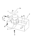
- FIG. 1 is a perspective view of a cutting state by a milling tool having a cylindrical tip.
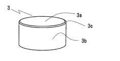
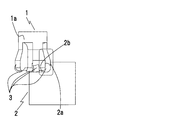
- FIG. 2A is a perspective view of the shape of a chip.
- FIG. 2B is a top view of the shape of the chip.
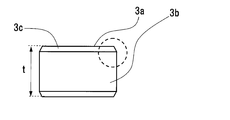
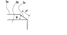
- FIG. 2C is a shape side view of the chip. 2D is an enlarged view of a dotted line portion in FIG. 2C.
- 3A is a front view in the direction of arrow B in FIG. 3B is a bottom view in the direction of arrow C in FIG. 3C is a side view in the direction of arrow A in FIG.
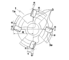
- FIG. 4A is a front view of a milling tool having cylindrical tips evenly arranged.
- FIG. 4B is a bottom view of a milling tool having cylindrical tips evenly arranged.
- FIG. 4A is a front view of a milling tool having cylindrical tips evenly arranged.
- FIG. 4B is a bottom view of a milling tool having cylindrical tips evenly arranged.
- FIG. 4A is
- FIG. 5 is a diagram showing a contact state between a tip and a YZ plane of a work material in a milling tool having a cylindrical tip.
- FIG. 6 is a diagram showing an axial mounting angle of a cylindrical chip.
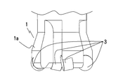
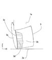
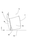
- FIG. 7 is a view showing a noticeable wear state generated in a wide range of the cylindrical tip by the arrangement shown in FIGS. 4A and 4B.
- FIG. 8A is a front view of a milling tool having a cylindrical tip according to the present invention.
- FIG. 8B is a bottom view of a milling tool having a cylindrical tip according to the present invention.
- FIG. 9 is a view showing a contact state between a tip and a YZ plane of a work material in a milling tool having a cylindrical tip according to the present invention.
- FIG. 10 is a view showing a contact state between the tip and the XZ plane of the work material in the milling tool having the cylindrical tip according to the present invention.
- FIG. 11 is a diagram showing a worn state generated on the bottom side of the cylindrical tip according to the present invention.
- FIG. 12 is a view showing a worn state generated on the side surface of the cylindrical tip according to the present invention.
- FIG. 13 is an enlarged view of FIG.
- FIG. 14 is a bottom view of a milling tool having a cylindrical tip according to another embodiment of the present invention.
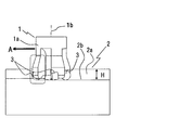
- FIG. 1 is a perspective view of a state in which an L-shaped work material having a standing wall surface is being cut using a milling tool having a round piece chip.
- 1 is a milling tool for cutting
- 2 is a work material.
- the milling tool 1 includes a tool main body 1a and a round piece chip 3 attached to the tip of the tool main body 1a.
- FIG. 2 shows a detailed shape of the chip 3
- FIG. 2A shows a perspective view
- FIG. 2B shows a top view
- FIG. 2C shows a side view
- FIG. 2D is an enlarged view of a dotted line portion in FIG. 2C.
- the tip 3 is a circular piece tip having a cylindrical shape with a diameter D and a thickness t, and as shown in FIG. 2A, a chamfered portion is formed on the rake face 3a, the flank face 3b, and the boundary between the rake face 3a and the flank face 3b. 3c.
- the chamfered portion 3c is an inclined surface having a chamfering width cf and a chamfering angle ⁇ with respect to the rake surface 3a.
- the chamfering angle ⁇ of the chip 3 is about ⁇ ⁇ 30 °
- the chamfering width cf is cf ⁇ 0.2 mm.
- the tip 3 is fixed to the tool main body 1a with a stopper, a screw or the like not shown.
- the milling tool 1 rotates about a tool rotation axis 1 b in a rotation direction 1 c, and the work material 2 is moved by moving the milling tool 1 in the direction of arrow A in the rotation state.
- the bottom surface 2b and the standing wall surface 2a are cut.
- the chips 3 are arranged at four positions in the circumferential direction with respect to the tool body 1 a and are attached so that the rake face 3 a is in the front direction with respect to the rotation direction of the milling tool 1.
- a standing wall surface 2 a and a bottom surface 2 b having a height H are formed on the work material 2.
- FIG. 3A to 3C show the cutting state of FIG. 1 in the direction of arrow B, arrow C, and arrow A, respectively.
- FIG. 3A is a front view in the B direction
- FIG. 3B is a bottom view in the direction of the arrow C
- 3C is a side view in the direction of arrow A
- the milling tool 1 moves straight in the direction of arrow A while maintaining the counterclockwise rotational motion 1c shown in FIG. Remove.
- the work material 2 is displaced by a distance d in the Z-axis direction with respect to the work material 2 so as to cut the work material 2 by a depth d in the Z direction. Remove.
- the vertical wall surface 2a and the bottom surface 2b having a height H are cut.
- 1d indicates a curved locus drawn by the tip of the chip 3. The tip 3 moves along a curved locus (1d) on the bottom surface 2a of the workpiece 2 along with the rotational motion 1c of the milling tool 1 and the linear movement in the direction of arrow A, and exists on the locus of the curved locus 1d.
- the work material 2 to be cut is cut.
- the curved locus 1d is a curved line drawn on the bottom surface 2b of the work material 2 at a pitch of the feed amount fz determined by the moving speed in the arrow A direction and the rotational speed of the rotation 1c.
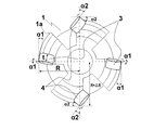
- FIGS. 4A and 4B show a milling tool in which circular chip tips are arranged at equal heights in the Z direction, radial positions with respect to the rotation axis, and mounting angles.
- FIG. 4A is a front view and FIG. 4B is a bottom view.
- the milling tool 1 is mounted such that the tip 3 is constant in the Z direction in the axial direction of the tool body 1.
- tip 3 is arrange
- when the inclination in the tool radial direction on the rake face 3a is defined as a radial mounting angle ⁇ , ⁇ in all the chips 3 is also set to be the same.
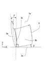
- FIG. 6 is an enlarged view of the dotted line portion shown in FIG. 3A viewed from the Y direction (see FIG. 1).
- the axial mounting angle ⁇ is the same for all the tips 3. That is, the radial mounting angle ⁇ (see FIG. 4B) and the axial mounting angle ⁇ are the same for all the chips 3. This is because, in the milling tool 1 shown in FIG. 4, the radial mounting angle ⁇ and the axial mounting angle ⁇ are designed on the assumption that the bottom surface 2b of the work material 2 is cut, and the standing wall 2a is removed. This is because it is not considered.
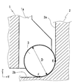
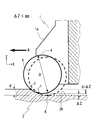
- FIG. 5 shows the Z ⁇ at the cutting edge contact portion of the workpiece 2 and the tip 3 indicated by the dotted line in FIG. 3C when the cutting shown in FIGS. 1 and 3 is performed using the milling tool 1 shown in FIG. It is an enlarged view of the Y plane.
- the tip 3 cuts the standing wall 2 a of the work material 2
- the portion of the outer peripheral surface of the tip 3 in the range indicated by the arc EF comes into contact with the work material 2.
- the circumference of the arc EF is equal to or more than a quarter of the circumference, and the chip 3 is cut in a state where a wide area is in contact with the outer periphery of the chip 3 at the same time.
- a remarkable wear region 3d is generated on the side surface 3b.
- the amount of wear at the contact portion E that is the side surface of the tip 3 is increased.
- FIG. 8 shows a front view and a bottom view of the milling tool 1 according to the present invention.
- FIG. 8A is a front view
- FIG. 8B is a bottom view.
- the milling tool 1 of the present embodiment is a tip 3 and a tip 4 that are different from each other in the diametrical position and the axial height position from the central axis 1b of the tool body 1a. They are arranged in pairs in the diameter direction.
- the chip 3 is disposed such that the radial mounting angle of the chip 3 is ⁇ 1 and the radial mounting angle of the chip 4 is ⁇ 2. Further, in the axial mounting angle, the chip 3 is disposed such that the axial mounting angle of the chip 3 is ⁇ 1 and the chip 4 is axially mounted.
- the tip 3 cuts the bottom surface portion 2 b with respect to the work material 2.
- the tip 4 cuts the standing wall surface 2a.
- R the radius of the locus of the circular arc drawn by the tip of the cutting edge of the milling tool 1
- the following three relational expressions must be geometrically satisfied. is necessary. ⁇ 1> 0 ° cos ⁇ 1> D / (2R) 0 ° ⁇ 1 ⁇ 90 °
- FIGS. 1 A method for setting appropriate values of ⁇ 1 and ⁇ 1 will be described with reference to FIGS. That is, the cutting experiment as shown in FIG. 1 is performed by changing the radial mounting angle ⁇ and the axial mounting angle ⁇ .
- the tip 3 is attached on the premise that the bottom surface portion 2b of the work material 2 is cut, a distance is set so that the tip 3 and the standing wall surface 2a of the work material 2 do not come into contact during the experiment, Only the bottom surface portion 2b is cut.
- the wear region 3 d is generated on the side surface 3 b of the chip 3.
- the work material 2 is cut, and the values ⁇ and ⁇ that reduce the width of the wear region 3d are set to the radial mounting angle ⁇ 1 and the axial mounting angle ⁇ 1 of the tip 3, respectively.
- the setting range 6 ° ⁇ 1 ⁇ 30 ° and 0 ° ⁇ 1 ⁇ 20 ° are appropriate.
- the tip 4 is positioned at a distance of ⁇ R from the center of the tool rotation shaft 1 a in the radial direction of the tool with respect to the tip 3. Will be cut.
- the thickness of the tip 4 is t and the radius of the arc locus drawn by the tip of the milling tool 1 is R, the standing wall surface 2a of the work material 2 and the flank 4b of the tip 4 do not interfere with each other. Needs to satisfy the following three relational expressions geometrically. sin ⁇ 2> t / 2 (R + ⁇ R) cos ⁇ 2> D / 2 (R + ⁇ R) 0 ° ⁇ 2 ⁇ 90 °
- a method of setting appropriate values of ⁇ 2 and ⁇ 2 will be described with reference to FIG. That is, the cutting experiment as shown in FIG. 1 is performed by changing the radial mounting angle ⁇ and the axial mounting angle ⁇ .
- the tip 3 is attached on the premise that the bottom surface portion 2b of the work material 2 is cut, a distance is set so that the tip 3 and the standing wall surface 2a of the work material 2 do not come into contact during the experiment, Only the bottom surface portion 2b is cut.
- the wear region 4d is generated on the side surface 4b of the chip 4.
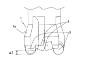
- FIG. 9 shows the Z-- at the cutting edge contact portion of the workpiece 2 and the tips 3 and 4 indicated by the dotted line in FIG. 3C when the cutting shown in FIGS. 1 and 2 is performed using the milling tool 1 of the present embodiment. It is an enlarged view of the Y plane.
- the tip 4 is separated from the tip 3 by a distance ⁇ R in the radial direction of the tool from the center of the tool rotation axis 1a, and a distance away from the bottom surface 2a of the work material 2 by ⁇ Z in the tool rotation axis direction. It is arranged in.
- both the tip 3 and the tip 4 have a cylindrical shape with the same diameter D and thickness t, and the mounting angles, ⁇ R, ⁇ Z of each tip are 3 on the tip mounting surface of the milling tool 1 body.
- the dimensional position it is set to a desired value.
- the cutting edge of the tip 3 is preferentially in the range of E′-F ′ for the bottom surface 2b of the work material 2, and the cutting edge of the tip 4 is preferentially in the range of GE ′ for the standing wall 2a.
- contact with the standing wall 2a does not occur in the chip 3, and contact with the bottom surface 2b does not occur with respect to the chip 4, and each contact range can be greatly reduced, and generation of wear is suppressed.
- the chip 3 can be individually assigned as the bottom surface cutting and the chip 4 as the standing wall surface cutting chip.
- FIG. 10 is a cross-sectional view of ZX at the cutting edge contact portion of the workpiece 2 and the chips 3 and 4 shown by the dotted line in FIG. 3A when the milling tool 1 of the present invention is used for cutting shown in FIGS. It is an enlarged view of a plane.
- the tip 4 is arranged in the tool body 1 so as to be a distance away from the tip 3 by ⁇ Z in the tool rotation axis direction.
- the cutting edge of the tip 4 can be contacted and removed preferentially in the range of JI with respect to the bottom surface 2b of the work material 2, and the cutting edge of the tip 3 can be contacted and removed with priority in the range of IK.
- the occurrence of wear can be suppressed by limiting the contact range of each blade edge.
- FIG. 11 For the tip 3 and FIG. 12 for the tip 4, the wear region 3d can be greatly reduced.
- a method of calculating ⁇ R and ⁇ Z will be described below.
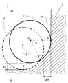
- An enlarged view of FIG. 9 is shown in FIG.
- the center point on the rake face of the chip 3 is P
- the center point on the rake face 4a of the chip 4 is Q.
- the angle ⁇ 1 formed by the contact arc E′F ′ between the tip 3 and the work material 2 with the point P as the center is defined as the cutting angle of the tip 3.
- an angle ⁇ 2 formed by the contact arc E′G between the tip 4 and the work material 2 around the point Q is defined as a cutting angle of the tip 4.
- ⁇ R can be designed from the equation (1) and ⁇ Z from the equation (2).
- ⁇ 1 and ⁇ 2 be at least 2/3 or less of the contact arc EF shown in FIG. 0 ⁇ 1, ⁇ 2 ⁇ 60 ° (3)
- ⁇ R and ⁇ Z are in the following ranges. 0 ⁇ R, ⁇ Z ⁇ 0.18 ⁇ D
- the milling tool 1 according to the present invention is most effective in cutting that causes significant tool wear when machining difficult-to-cut materials such as heat-resistant alloys.
- a ceramic tool was applied as the material of the chip 3 and the chip 4 in consideration of heat resistance during high-efficiency processing.
- Example 2 As another embodiment of the present invention, the thickness t of the tip 4 is changed and attached to the main body of the milling tool 1.
- FIG. 14 shows a bottom view of this embodiment, and is a bottom view showing the milling tool 1 from the same direction as FIG. 8B used in the description of the first embodiment.
- a chip having a chip thickness t2 is disposed on the chip 4, and the radial mounting angle of the chip 3 is ⁇ 1, and the axial mounting angle is ⁇ 1.
- ⁇ 1 and ⁇ 1 are set in the same manner as in the first embodiment.
- the tip 4 is positioned at a distance of ⁇ R from the center of the tool rotating shaft 1a in the radial direction of the tool by cutting the standing wall surface 2a of the work material 2 with respect to the tip 3.
- ⁇ R the thickness of the tip 4
- R the radius of the arc locus drawn by the tip of the milling tool 1
- the standing wall surface 2a of the work material 2 and the flank 4b of the tip 4 do not interfere with each other. Needs to satisfy the following three relational expressions geometrically.
- the radial mounting angle and the radial clearance angle have the same relationship.
- the smaller the clearance angle the higher the cutting edge strength and the higher the wear resistance and chipping properties.
- the clearance angle also increases when the tip thickness is large. Therefore, in this embodiment, the contact range of the tip 4 is limited to the standing wall surface 2a of the work material 2 and the contact on the bottom side is greatly reduced, so that the cutting load of the tip 4 can be reduced.
- the thickness t2 of the tip 4 can be reduced and the clearance angle of the tip 4 can be reduced, so that the cutting edge strength can be increased and the milling tool 1 having high wear resistance can be configured.
- the degree of freedom in setting the radial mounting angle ⁇ 2 is improved, so that the mounting angles of the tip 3 and the tip 4 are suitable for cutting the standing wall surface 2a side and the bottom surface 2b side of the work material 2, respectively. Therefore, it is possible to construct a tool having excellent wear resistance and long life.
- the radial mounting angle ⁇ must be set to 9.2 ° or more.
- ⁇ R in FIG. 9 is set to 0.5 mm
- the thickness t2 of the tip 4 is set to 5 mm, so that the radial mounting angle of the tip 4 can be set to 6 °, and the cutting edge strength is excellent.
- a milling tool 1 can be constructed.
- this invention is not limited to the above-mentioned Example, Various modifications are included.
- the ceramic material tool suitable for the cutting of the super heat resistant alloy has been described.
- the material of the tool is not limited, and a cemented carbide material may be used.
- the material of the work material is effective even if it is not a super heat-resistant alloy, and the same effect can be obtained by processing ordinary steel material, stainless steel material or high hardness material.
- four circular circular piece chips are provided at 90 ° intervals in the circumferential direction, divided into two sets facing each other on the diameter, and one set of chips 3 is used for bottom cutting, and the other set.
- six cylindrical round piece chips are provided at intervals of 60 °, they may be assigned to two sets at intervals of 120 °.
- three or more sets of cylindrical round piece chips arranged at the same circumferential angle are set, and at least one of the sets is set.
- Various modifications are possible, such as a set of round piece chips for cutting the bottom surface of the work material or a set of round piece chips for cutting the standing wall surface of the work material.
- cutting can be performed with high efficiency by simply displacing the tip mounting angle, the distance in the tool radial direction from the center of the tool rotation axis, and the distance in the tool rotation axis direction. Furthermore, even when standing wall surfaces are formed, abnormal wear on the side surface of the blade edge is suppressed, enabling long-life cutting, especially for roughing with difficult-to-cut materials such as super heat-resistant alloys. Expected to be widely adopted.
Landscapes
- Engineering & Computer Science (AREA)
- Mechanical Engineering (AREA)
- Milling Processes (AREA)
Abstract
超耐熱合金などの難削材での荒加工において、高能率の切削を可能にするとともに、立壁面が形成される場合にも、刃先側面部の異常摩耗を抑制し、高寿命の切削加工を可能とする。 複数の円筒状丸駒チップが円周方向に同一間隔で配置されたフライス工具において、丸駒チップを、フライス工具の工具回転軸を中心に同一円周角度毎に配置された丸駒チップの組に分ける。そして、その少なくとも一組について、チップ取り付け角、工具回転軸の軸中心から工具の半径方向の距離及び工具回転軸方向の距離を、他の組に対し変位させることにより、被削材の底面の切削を行う丸駒チップの組と、被削材の立壁面の切削を行う丸駒チップの組とに分担を設ける。
Description
本発明は切削加工に用いるフライス工具に関し、特に超耐熱合金などの難削材の切削加工に使用する刃先交換式のフライス工具に関する。
この種の刃先交換式チップを有するフライス工具は、金型加工や素材の切削加工に広く使用される回転工具であり、チップ形状としては多角形状のものと、刃先によるすくい面が円形状の、いわゆる丸駒チップとが知られている。
通常、平面形状を削り落とす際には、チップの断面が四角形等の多角形状であるチップを使用したフライス工具が用いられる。しかし、チップが多角形状であるため、3次元形状の掘り込み加工などでは階段状の加工となり、仕上げ加工での取代にムラが生じ、精密形状の仕上げには不適となる。また、切削抵抗が大きく、工具の変形が生じやすい。
通常、平面形状を削り落とす際には、チップの断面が四角形等の多角形状であるチップを使用したフライス工具が用いられる。しかし、チップが多角形状であるため、3次元形状の掘り込み加工などでは階段状の加工となり、仕上げ加工での取代にムラが生じ、精密形状の仕上げには不適となる。また、切削抵抗が大きく、工具の変形が生じやすい。
一方、丸駒チップを用いたフライス工具は、すくい面が円形状の丸駒チップを、回転工具の円周方向に複数配置したものであり、切削負荷を円形の刃先全体で分散して受け止めるので応力集中などが発生しにくく、欠損しにくいことから、難削材の切削加工に対し耐久性が高いという利点がある。また、刃先が円形状であるため、パスとパスとのつなぎがスムースで、次工程の取代を均一にできるほか、刃先の軌道上の形状が曲面であることから3次元形状の製品も作成しやすい。
さらに、切削点での切りくず厚さは切込角が0°(極めて薄いカット)から90°に滑らかに変化するため、送りを高く設定することができ、荒加工には特に有用である。
しかも、丸駒チップは、円形状の全周囲を刃先として使用できるため、その一部が摩耗した際には、チップを少し回転することで新しい切削点を設定することができ、コスト面でも有利となる。
さらに、切削点での切りくず厚さは切込角が0°(極めて薄いカット)から90°に滑らかに変化するため、送りを高く設定することができ、荒加工には特に有用である。
しかも、丸駒チップは、円形状の全周囲を刃先として使用できるため、その一部が摩耗した際には、チップを少し回転することで新しい切削点を設定することができ、コスト面でも有利となる。
こうした利点から、金型加工や外形削り出し工程での荒加工や中仕上げ加工、さらには、超耐熱合金をはじめとする難削材の荒加工においても多く用いられるようになってきているが、丸駒チップに超硬金属材を用いた場合でも、難削材の切削加工に伴い、寿命が極端に低下する場合があり、切削速度の低下や、工具交換頻度の増大など加工能率の低下が問題となる。
そこで、近年のセラミックス素材の性能向上を背景として、丸駒チップ素材として、高硬度でしかも強度がきわめて高いセラミックスを採用し、高速の切削加工を行うことにより、高い除去能率で超耐熱合金の切削加工も可能となってきている。
そこで、近年のセラミックス素材の性能向上を背景として、丸駒チップ素材として、高硬度でしかも強度がきわめて高いセラミックスを採用し、高速の切削加工を行うことにより、高い除去能率で超耐熱合金の切削加工も可能となってきている。
しかし、こうしたセラミックスの丸駒チップは、製造コストの面から形状が単純な円筒形状で供給されるため、チップ単体では、円筒側面の逃げ角が確保できない。
そのため、丸駒チップを使用したフライス工具による加工は、底面側の逃げ角が確保されるよう取り付け面の角度が設計することにより、底面側での切削を行うことが一般的である。
そのため、丸駒チップを使用したフライス工具による加工は、底面側の逃げ角が確保されるよう取り付け面の角度が設計することにより、底面側での切削を行うことが一般的である。
ところが、3次元形状の掘り込み切削加工を行う場合では、底面側の切削のみならず、加工形状の制約から90°の傾斜面を有する立ち壁面を切削することが必要となる。このように立ち壁面を切削する場合には、丸駒チップの円形刃先のうち、底面側切削点から側面の切削点に至るまで、90°以上が接触部となり、切削力が大きく、しかも切り屑排出性が低下することから、側面部での摩耗増大や欠損の要因となる。特に、超耐熱合金の切削で有効となるセラミックス素材の丸駒チップでは、その側面部の摩耗増加は顕著である。また、チップが円筒形状をしていることから、逃げ角が十分とれないため、摩耗増大時には工具本体が被削材と接触する可能性があり、加工上の不具合となる。
このような底面と側面部での接触部に関わる従来技術として、例えば、下記特許文献1には、長方形チップ形状の刃先交換式工具において、半径方向と軸方向の突出し量を変化させることにより、底面と側面の切削領域を変化させて切削時の切削抵抗の低減を図り、摩耗の要因となる、びびり振動の発生を抑制させる工具が開示されている。また、下記特許文献2には、底面切削用チップと側面切削用チップを別々に配置した工具が開示されている。
特許文献1では、チップ交換型フライス工具において、四角形状のチップの取り付け位置のオフセット量を定め、その回転軌跡を互いに変位させることにより、びびり、規則的な振動を防止している。しかし、あくまでも、四角形状のチップの切削点の変位を前提としていることから、刃先が円形状となる円筒状の丸駒チップを使用したフライス工具には適用できない。
すなわち、円筒形状の丸駒チップにおいては、軸方向、半径方向にオフセットしただけではチップ側面部での逃げ角が確保されず、立ち壁面の切削が考慮されていないため、チップ側面の異常摩耗抑制のための効果は得られない。
すなわち、円筒形状の丸駒チップにおいては、軸方向、半径方向にオフセットしただけではチップ側面部での逃げ角が確保されず、立ち壁面の切削が考慮されていないため、チップ側面の異常摩耗抑制のための効果は得られない。
特許文献2においても、四角形状のチップで底面切削用の刃先と側面切削用の刃先を形成しているため、丸駒チップのフライス工具に適用することはできない。
そこで、本発明の目的は、特にセラミックス素材の円筒状の丸駒チップを、超耐熱合金などの難削材での荒加工に使用した場合でも、高能率で切削が可能にするとともに、加工形状の制約で立ち壁面が形成される場合にも、刃先側面部の異常摩耗を抑制し、高寿命の切削加工が可能な工具を提供することにある。
そこで、本発明の目的は、特にセラミックス素材の円筒状の丸駒チップを、超耐熱合金などの難削材での荒加工に使用した場合でも、高能率で切削が可能にするとともに、加工形状の制約で立ち壁面が形成される場合にも、刃先側面部の異常摩耗を抑制し、高寿命の切削加工が可能な工具を提供することにある。
この目的を達成するため、本発明のフライス工具は、複数の円筒状丸駒チップが円周方向に同一間隔で配置されたフライス工具において、前記丸駒チップを、フライス工具の工具回転軸を中心に同一円周角度毎に配置された丸駒チップの組に分け、少なくともその一組について、チップ取り付け角、工具回転軸の軸中心から工具の半径方向の距離及び工具回転軸方向の距離を、他の組に対し変位させることにより、被削材の底面の切削を行う丸駒チップの組と、被削材の立壁面の切削を行う丸駒チップの組とに分担を設けた。
また、上記のフライス工具において、前記被削材の底面の切削を行う丸駒チップの組における被削材の接触範囲と、前記被削材の立壁面の切削を行う丸駒チップの組における被削材の接触範囲を、工具回転軸の軸中心から工具の半径方向の距離及び工具回転軸方向の距離により設定した。
さらに、上記のフライス工具において、前記丸駒チップの厚さを選定することにより、前記チップの工具回転軸の軸中心から工具の半径方向の距離及び工具回転軸方向の距離を変位させた。
上記のフライス工具に取り付けられる丸駒チップのセットとして、厚さの異なる丸駒チップの組み合わせで構成した。
本発明によれば、超耐熱合金などの難削材における切削加工において、高能率かつ長寿命となる切削工具を提供することができる。上記した以外の課題、構成及び効果は、以下の実施形態の説明により明らかにされる。
以下、本発明の実施の形態を、図面を用いて説明する。
最初に、本発明の前提となる、円筒形状の丸駒チップを使用したフライス工具による切削加工について説明する。
図1は、丸駒チップを有するフライス工具を用いて、立ち壁面を有するL型状の被削材を切削している状態の斜視図である。
図1において、1は切削を行うフライス工具であり、2は被削材である。フライス工具1は、工具本体1aと、工具本体1aの先端に取り付けられた丸駒チップ3とから構成されている。
最初に、本発明の前提となる、円筒形状の丸駒チップを使用したフライス工具による切削加工について説明する。
図1は、丸駒チップを有するフライス工具を用いて、立ち壁面を有するL型状の被削材を切削している状態の斜視図である。
図1において、1は切削を行うフライス工具であり、2は被削材である。フライス工具1は、工具本体1aと、工具本体1aの先端に取り付けられた丸駒チップ3とから構成されている。
図2はチップ3の詳細な形状を示したのもので、図2Aは斜視図、図2Bは上面図、図2Cは側面図をそれぞれ示しており、図2Dは図2Cにおける点線部の拡大図である。
チップ3は、直径D、厚さtの円柱形状を有する丸駒チップであり、図2Aに示されるように、すくい面3a、逃げ面3b、及びすくい面3aと逃げ面3bの境界に面取り部3cを有している。面取り部3cは、すくい面3aに対して面取り幅cf、面取り角θの傾斜面である。チップ3の面取り角θは、θ<30°程度、面取り幅cfは、cf≦0.2mmとするのが一般的である。
チップ3は、直径D、厚さtの円柱形状を有する丸駒チップであり、図2Aに示されるように、すくい面3a、逃げ面3b、及びすくい面3aと逃げ面3bの境界に面取り部3cを有している。面取り部3cは、すくい面3aに対して面取り幅cf、面取り角θの傾斜面である。チップ3の面取り角θは、θ<30°程度、面取り幅cfは、cf≦0.2mmとするのが一般的である。
チップ3は工具本体1aに対して図示していない止め具やネジ等で固定されている。フライス工具1は、図1に示されるように、工具回転軸1bを中心に回転方向1cで回転しており、回転状態にてフライス工具1を矢印A方向に移動させることにより、被削材2の底面2bと立ち壁面2aを切削する。チップ3は、工具本体1aに対して円周方向4箇所に配置され、すくい面3aがフライス工具1の回転方向に対して正面方向となるように取り付けられている。このフライス工具1による切削加工により、被削材2には、高さHの立壁面2aと底面2bが形成される。
図3A~図3Cは、図1の切削状態を矢印B方向、矢印C方向及び矢印A方向をそれぞれ示したもので、図3AはB方向の正面図、図3Bは矢印C方向の下面図、そして図3Cは矢印A方向の側面図であり、フライス工具1は、図3Bに示される反時計方向の回転運動1cを維持したまま、矢印A方向に直進して被削材2の底面2bを除去する。
図3A~図3Cは、図1の切削状態を矢印B方向、矢印C方向及び矢印A方向をそれぞれ示したもので、図3AはB方向の正面図、図3Bは矢印C方向の下面図、そして図3Cは矢印A方向の側面図であり、フライス工具1は、図3Bに示される反時計方向の回転運動1cを維持したまま、矢印A方向に直進して被削材2の底面2bを除去する。
この際、フライス工具1の矢印方向Aの移動に先立ち、被削材2に対してZ軸方向に距離dだけ変位させて切込みを与えることで、被削材2をZ方向の深さdだけ除去する。この動作を繰り返すことにより、高さHの立壁面2aと底面2bの切削が行われる。
図3Bにおいて、1dはチップ3の先端が描く曲線軌跡を示している。
チップ3はフライス工具1の回転運動1c及び矢印A方向への直進運動に伴い、チップ3は被削材2の底面2a上を曲線軌跡(1d)で移動し、曲線軌跡1dの軌跡上に存在する被削材2を切削する。ここで、曲線軌跡1dは、矢印A方向の移動速度と回転1cの回転数より定まる送り量fzのピッチで、被削材2の底面2b上に描かれる曲線となる。
図3Bにおいて、1dはチップ3の先端が描く曲線軌跡を示している。
チップ3はフライス工具1の回転運動1c及び矢印A方向への直進運動に伴い、チップ3は被削材2の底面2a上を曲線軌跡(1d)で移動し、曲線軌跡1dの軌跡上に存在する被削材2を切削する。ここで、曲線軌跡1dは、矢印A方向の移動速度と回転1cの回転数より定まる送り量fzのピッチで、被削材2の底面2b上に描かれる曲線となる。
ここで図4、図5を用いて、丸駒チップを均等配置した場合のフライス工具1を用いて図1、2に示した切削を行う場合の問題点を説明する。図4は、丸駒チップを、Z方向の高さ、回転軸に対する半径方向位置及び取り付け角を均等配置したフライス工具を示したもので、図4Aは正面図、図4Bは底面図である。
このフライス工具1は、チップ3が工具本体1の軸方向において、いずれのチップ3もZ方向の高さが一定となるように取付けられている。また、図4Bに示すように、それぞれのチップ3は回転軸1bに対して同じ距離Rで配置されている。また、図4Bにおいて、すくい面3aにおける工具半径方向の傾きを半径方向取り付け角αとすると、すべてのチップ3におけるαも同一に設定されている。
このフライス工具1は、チップ3が工具本体1の軸方向において、いずれのチップ3もZ方向の高さが一定となるように取付けられている。また、図4Bに示すように、それぞれのチップ3は回転軸1bに対して同じ距離Rで配置されている。また、図4Bにおいて、すくい面3aにおける工具半径方向の傾きを半径方向取り付け角αとすると、すべてのチップ3におけるαも同一に設定されている。
ここで、図6は、図3Aに示す点線部をY方向(図1参照)より見た拡大図である。フライス工具1の軸方向に対するチップ3の傾きを軸方向取り付け角βとすると、すべてのチップ3についても軸方向取り付け角βは同一となっている。すなわち、半径方向取り付け角α(図4B参照)、軸方向取り付け角βは、すべてのチップ3で同一である。これは、図4に示したフライス工具1では被削材2の底面2bを切削することを前提に、半径方向取り付け角α、軸方向取り付け角βが設計されており、立壁面2aを除去することは考慮されていないためである。
図5は、図4に示したフライス工具1を用いて図1、3に示す切削を行った際の、図3C中の点線部で示す被削材2とチップ3の刃先接触部におけるZ-Y平面の拡大図である。
図5において、チップ3が被削材2の立壁面2aを切削する際には、チップ3の外周面は円弧E-Fで示す範囲の部分が、被削材2と接触することとなる。チップ3において円弧E-Fの周長は、円周の4分の1以上であり、チップ3の外周部で広範囲の部分が同時に接触した状態で切削されるため、チップ3には図7の斜視図で示すように、側面3bには、顕著な摩耗領域3dが発生する。特に、チップ3の側面側である接触部Eでの摩耗量が大きくなる。
図5において、チップ3が被削材2の立壁面2aを切削する際には、チップ3の外周面は円弧E-Fで示す範囲の部分が、被削材2と接触することとなる。チップ3において円弧E-Fの周長は、円周の4分の1以上であり、チップ3の外周部で広範囲の部分が同時に接触した状態で切削されるため、チップ3には図7の斜視図で示すように、側面3bには、顕著な摩耗領域3dが発生する。特に、チップ3の側面側である接触部Eでの摩耗量が大きくなる。
上記したフライス工具1の場合、工具本体1に対してすべてのチップ3が同じ配置で取り付けられているため、立壁面2aとの接触状態はすべてのチップで同じものとなり、同様の摩耗が発生する。この結果、側面側である接触部付近ではチップ3の刃先後退により工具本体1の側面部と被削材2の接触が発生することとなり、切削の継続が困難となる。特に、円筒形状をしたチップ3では、図4B及び図6に示す半径方向取り付け角α、軸方向取り付け角βは、被削材2の底面部2bを除去することを重点に設定されているため、立ち壁面2aの接触時には、側面部での摩耗が顕著となる。
[実施例1]
次に、本発明におけるフライス工具の1例を、図8を用いて説明する。図8は、本発明によるフライス工具1の正面図、底面図を示したもので、図8Aは正面図、図8Bは底面図である。
本実施例のフライス工具1は、工具本体1aの中心軸1bからの直径方向の位置と軸方向の高さ位置が異なるチップ3とチップ4であり、円周上に90°間隔で、それぞれ、直径方向に2個一組に配置されている。そして、図8Bに示す円周方向の取り付け角度において、チップ3の半径方向取り付け角がα1、チップ4の半径方向取り付け角がα2となるように配置されている。また、軸方向の取り付け角度において、チップ3の軸方向取り付け角がβ1、チップ4の軸方向取り付け角がβ2となるように配置されている。
まず、α1及びβ1の設定方法を図9で説明する。図9に示すとおり被削材2に対してチップ3は底面部2bを切削する。同様に、チップ4は立壁面2aを切削する。ここで、フライス工具1の刃先先端が描く円弧の軌跡の半径をRとしたとき、チップ3が被削材2を切削するためには、幾何学的に以下の3つの関係式を満たすことが必要である。
α1>0°
cosα1>D/(2R)
0°<β1<90°
α1>0°
cosα1>D/(2R)
0°<β1<90°
α1及びβ1の適正値設定方法を図1、図11で説明する。すなわち、半径方向取り付け角α及び軸方向取り付け角βを変更して、図1に示すような切削実験を行う。なお、チップ3は被削材2の底面部2bを切削することを前提に取り付けられているため、実験時に際してはチップ3と被削材2の立壁面2aを接触させないように距離を置き、底面部2bのみを切削する。
このとき、図11に示すようにチップ3には、側面3bに摩耗領域3dが発生する。実験では、被削材2を切削し、摩耗領域3dの幅が小さくなるα及びβの値を、それぞれチップ3の半径方向取り付け角α1及び軸方向取り付け角β1に設定する。設定範囲としては6°<α1<30°、0°<β1<20°程度が適当であり、本実施例ではα1=12°、β1=6°とした。
このとき、図11に示すようにチップ3には、側面3bに摩耗領域3dが発生する。実験では、被削材2を切削し、摩耗領域3dの幅が小さくなるα及びβの値を、それぞれチップ3の半径方向取り付け角α1及び軸方向取り付け角β1に設定する。設定範囲としては6°<α1<30°、0°<β1<20°程度が適当であり、本実施例ではα1=12°、β1=6°とした。
次に、α2及びβ2についての設定方法を図1、図9、図12で説明する。図9で示しているとおり、チップ3に対してチップ4は工具回転軸1aの軸中心から工具の半径方向にΔRだけ離れた距離に位置させたことにより、被削材2の立壁面2aを切削することとなる。ここでチップ4の厚さをtとし、フライス工具1の刃先先端が描く円弧の軌跡の半径をRとしたとき、被削材2の立ち壁面2aとチップ4の逃げ面4bが干渉しないためには、幾何学的に以下の3つの関係式を満たすことが必要である。
sinα2>t/2(R+ΔR)
cosα2>D/2(R+ΔR)
0°<β2<90°
sinα2>t/2(R+ΔR)
cosα2>D/2(R+ΔR)
0°<β2<90°
α2及びβ2の適正値の設定方法を図1で説明する。すなわち、半径方向取り付け角α及び軸方向取り付け角βを変更して図1に示すような切削実験を行う。なお、チップ3は被削材2の底面部2bを切削することを前提に取り付けられているため、実験時に際してはチップ3と被削材2の立壁面2aを接触させないように距離を置き、底面部2bのみを切削する。このとき、図12に示すようにチップ4には、側面4bに摩耗領域4dが発生する。
実験では、被削材2を一定量切削除去し、摩耗領域4dの幅が小さくなったときのα及びβを、それぞれチップ4の半径方向取り付け角α2及び軸方向取り付け角β2に設定する。設定範囲としては10°<α2<45°、0°<β2<30°程度が適当であり、本実施例ではα2=7°、β2=12°とした。
実験では、被削材2を一定量切削除去し、摩耗領域4dの幅が小さくなったときのα及びβを、それぞれチップ4の半径方向取り付け角α2及び軸方向取り付け角β2に設定する。設定範囲としては10°<α2<45°、0°<β2<30°程度が適当であり、本実施例ではα2=7°、β2=12°とした。
図9は、本実施例のフライス工具1を用いて図1、2に示す切削を行った際の、図3Cの点線部で示す被削材2とチップ3、4の刃先接触部におけるZ-Y平面の拡大図である。チップ4はチップ3に対して、工具回転軸1aの軸中心から工具の半径方向にΔRだけ離れた距離に、そして、工具回転軸方向に、ΔZだけ被削材2の底面2aから離れた距離に配置してある。
なお、この実施例では、チップ3とチップ4は、ともに同一直径D、厚さtの円柱形状を有し、各チップの取り付け角、ΔR、ΔZは、フライス工具1本体のチップ取り付け面の3次元位置を設計することにより、所望の値に設定される。
なお、この実施例では、チップ3とチップ4は、ともに同一直径D、厚さtの円柱形状を有し、各チップの取り付け角、ΔR、ΔZは、フライス工具1本体のチップ取り付け面の3次元位置を設計することにより、所望の値に設定される。
これにより、切削時には被削材2の底面2bについては、チップ3の刃先がE’-F’の範囲で、そして立壁面2aについては、チップ4の刃先がG-E’の範囲で優先的に接触して除去できる。このため、チップ3には立壁面2aに対する接触が発生しなくなり、チップ4については、底面2bに対する接触が発生しなくなり、それぞれの接触範囲を大幅に減じることができ、摩耗の発生を抑制することが可能となる。すなわち、チップ3を底面切削用、チップ4を立壁面切削用チップとして、個別に分担させることができる。
図10は、本発明方式のフライス工具1を用いて図1、3に示した切削時の、図3Aの点線部で示す被削材2とチップ3、4の刃先接触部における、Z-X平面の拡大図である。
フライス工具を矢印A方向に移動させて切削加工を進行させる際、チップ4はチップ3に対して、工具回転軸方向にΔZだけ離れた距離となるように工具本体1に配置しているから、被削材2の底面2bに対してJ-Iの範囲でチップ4の刃先を優先的に接触させて除去でき、I-Kの範囲でチップ3の刃先を優先的に接触されて除去できるから、それぞれの刃先の接触範囲が限定されたものとなることで摩耗の発生を抑制することが可能である。
フライス工具を矢印A方向に移動させて切削加工を進行させる際、チップ4はチップ3に対して、工具回転軸方向にΔZだけ離れた距離となるように工具本体1に配置しているから、被削材2の底面2bに対してJ-Iの範囲でチップ4の刃先を優先的に接触させて除去でき、I-Kの範囲でチップ3の刃先を優先的に接触されて除去できるから、それぞれの刃先の接触範囲が限定されたものとなることで摩耗の発生を抑制することが可能である。
その結果、チップ3については図11、チップ4については図12に示すように、摩耗領域3dを大幅に低減することができる。ここで、ΔR、ΔZの算出方法を以下に説明する。図9の拡大図を図13に示す。チップ3のすくい面における中心点をP、チップ4のすくい面4aにおける中心点をQとした。図11より、点Pを中心に、チップ3と被削材2の接触円弧E’F’のなす角度φ1をチップ3の切込角とする。同様に、点Qを中心に、チップ4と被削材2の接触円弧E’Gのなす角度φ2をチップ4の切込角とする。
ここで、図13の点F’を原点とするY-Z座標系をとると、E’の座標(Y、Z)は、チップ3、4のすくい面の直径をともにDとしたとき、
Y=(D/2)×sinφ1、 Z=(D/2)×(1-cosφ1)
と近似できる。
また、E’の座標(Y、Z)はチップ4の切込み角φ2を用いて以下のように算出できる。
Y=ΔR+(D/2)×sin(90-φ2)
Z=ΔZ+(D/2)×{1-cos(90-φ2)}
よって、
ΔR+(D/2)×sin(90-φ2)=(D/2)×sinφ1・・・(1)
ΔZ+(D/2)×{1-cos(90-φ2)}=(D/2)×(1-cosφ1)・・・(2)
Y=(D/2)×sinφ1、 Z=(D/2)×(1-cosφ1)
と近似できる。
また、E’の座標(Y、Z)はチップ4の切込み角φ2を用いて以下のように算出できる。
Y=ΔR+(D/2)×sin(90-φ2)
Z=ΔZ+(D/2)×{1-cos(90-φ2)}
よって、
ΔR+(D/2)×sin(90-φ2)=(D/2)×sinφ1・・・(1)
ΔZ+(D/2)×{1-cos(90-φ2)}=(D/2)×(1-cosφ1)・・・(2)
したがって、チップ3、4の接触円弧を所望の値にする場合、上記(1)の式よりΔRを、(2)の式よりΔZを設計できる。
ここで、チップ3及び4における接触円弧の低減を考えると、φ1、φ2は少なくとも図5に示す接触円弧EFに対して2/3以下、すなわち以下の範囲であることが望ましい。
0 < φ1、φ2 <60°・・・・・・(3)
(1)式、(2)式、(3)式より、ΔR、ΔZは以下の範囲となる。
0 <ΔR、ΔZ <0.18×D
ここで、チップ3及び4における接触円弧の低減を考えると、φ1、φ2は少なくとも図5に示す接触円弧EFに対して2/3以下、すなわち以下の範囲であることが望ましい。
0 < φ1、φ2 <60°・・・・・・(3)
(1)式、(2)式、(3)式より、ΔR、ΔZは以下の範囲となる。
0 <ΔR、ΔZ <0.18×D
以下、本発明における具体的な実施例について説明する。本発明によるフライス工具1が最も効果が得られるのは、耐熱合金などの難削材の加工で、工具摩耗が顕著に発生する切削である。耐熱合金加工の工具ではチップ3及びチップ4の材質として、高能率加工時の耐熱性を考慮し、セラミックス工具を適用した。チップ3、4の直径Dには、D=12.7mmを選択した。被削材2において立ち壁面2aが形成されない形状での予備実験より、切込み角の適正範囲は50°以下が適正であることが判明した。そこで、φ1=φ2=50°として計算し、ΔR=ΔZ=0.062Dが得られる。
この場合、チップ3及びチップ4の直径にはD=12.7mmのチップを選定したため、この場合の ΔR、ΔZは、ΔR=ΔZ=0.79mmと算出できる。
この場合、チップ3及びチップ4の直径にはD=12.7mmのチップを選定したため、この場合の ΔR、ΔZは、ΔR=ΔZ=0.79mmと算出できる。
[実施例2]
本発明の他の実施例として、チップ4の厚さtを変更して、フライス工具1の本体に取り付ける。
図14は、この実施例の底面図を示したもので、実施例1の説明で用いた図8Bと同方向よりフライス工具1を示した底面図である。図14において、チップ4には、チップ厚さt2のチップを配置し、チップ3の半径方向取り付け角をα1、軸方向取り付け角をβ1としている。
α1及びβ1の設定は実施例1と同様に行う。
本発明の他の実施例として、チップ4の厚さtを変更して、フライス工具1の本体に取り付ける。
図14は、この実施例の底面図を示したもので、実施例1の説明で用いた図8Bと同方向よりフライス工具1を示した底面図である。図14において、チップ4には、チップ厚さt2のチップを配置し、チップ3の半径方向取り付け角をα1、軸方向取り付け角をβ1としている。
α1及びβ1の設定は実施例1と同様に行う。
図9で説明したとおり、チップ3に対してチップ4は工具回転軸1aの軸中心から工具の半径方向にΔRだけ離れた距離に位置させたことにより、被削材2の立壁面2aを切削することとなる。ここでチップ4の厚さをt2とし、フライス工具1の刃先先端が描く円弧の軌跡の半径をRとしたとき、被削材2の立ち壁面2aとチップ4の逃げ面4bが干渉しないためには、幾何学的に以下の3つの関係式を満たすことが必要である。
sinα2>t2/2(R+ΔR)
cosα2>D/2(R+ΔR)
0°<β2<90°
また、α2及びβ2の適正値設定は実施例1と同様に行う。
sinα2>t2/2(R+ΔR)
cosα2>D/2(R+ΔR)
0°<β2<90°
また、α2及びβ2の適正値設定は実施例1と同様に行う。
チップ4は円筒形状であるため、半径方向取り付け角と半径方向逃げ角は等しい関係にある。逃げ角は小さいほど、刃先強度は向上し、耐摩耗・チッピング性は向上するが、上記関係式があるため、チップ厚さが大きい場合、逃げ角も大きくなってしまう。
そこで、この実施例では、チップ4の接触範囲を被削材2の立ち壁面2aに限定させており、底面側での接触を大幅に減少させているため、チップ4の切削負荷が低減できる。これによりチップ4の厚さt2を小さくでき、チップ4の逃げ角を小さくすることができるため、刃先強度を高めて、耐摩耗性の高いフライス工具1を構成することが可能となる。
そこで、この実施例では、チップ4の接触範囲を被削材2の立ち壁面2aに限定させており、底面側での接触を大幅に減少させているため、チップ4の切削負荷が低減できる。これによりチップ4の厚さt2を小さくでき、チップ4の逃げ角を小さくすることができるため、刃先強度を高めて、耐摩耗性の高いフライス工具1を構成することが可能となる。
また、半径方向取り付け角α2の設定の自由度が向上することで、チップ3とチップ4の取り付け角を、それぞれ被削材2の立ち壁面2a側、底面2b側を切削するのに適した条件に設定することができ、耐摩耗性に優れ長寿命な工具が構成できる。
例えば、従来方式のフライス工具1では、チップ3の厚さを8mm、工具最外周部の公転半径25mmとした場合、半径方向取り付け角αは9.2°以上に設定しなくてはならないが、本実施例では、図9におけるΔRを0.5mmに設定し、チップ4の厚さt2を5mmとすることで、チップ4の半径方向取り付け角を6°に設定可能であり、刃先強度に優れたフライス工具1を構成できる。
例えば、従来方式のフライス工具1では、チップ3の厚さを8mm、工具最外周部の公転半径25mmとした場合、半径方向取り付け角αは9.2°以上に設定しなくてはならないが、本実施例では、図9におけるΔRを0.5mmに設定し、チップ4の厚さt2を5mmとすることで、チップ4の半径方向取り付け角を6°に設定可能であり、刃先強度に優れたフライス工具1を構成できる。
なお、本発明は上記した実施例に限定されるものではなく、様々な変形例が含まれる。例えば、最も効果が得られる方法として、超耐熱合金の切削加工に適したセラミックス素材の工具で説明したが、工具の素材を限定するものではなく、超硬素材でもよい。また、被削材の材質は、超耐熱合金以外でも効果があり、普通鋼材、ステンレス材や高硬度材などの加工でも同様の効果が得られる。
上記した実施例では、円筒状丸駒チップが円周方向に90°間隔に4個設け、直径上に対向する2個の組に分け、一方の組のチップ3を底面切削用、他方の組を立壁面切削用として分担させたが、例えば、円筒状丸駒チップを60°間隔に6個設けた場合、120°間隔で、二組に分担させてもよい。さらに多数の丸駒チップを円周方向に同一間隔で配置されたフライス工具の場合、同一円周角度毎に配置された円筒状丸駒チップの組を3組以上とし、その少なくともその一組を、被削材の底面の切削を行う丸駒チップの組あるいは、被削材の立壁面の切削を行う丸駒チップの組とするなど、さまざまな変更が可能である。
以上説明したように、本発明によれば、チップ取り付け角、工具回転軸の軸中心から工具の半径方向の距離及び工具回転軸方向の距離を変位させるだけで、高能率で切削が可能になり、さらには、立壁面が形成される場合にも、刃先側面部の異常摩耗を抑制し、高寿命の切削加工を可能とするので、特に超耐熱合金などの難削材での荒加工等に広く採用されることが期待される。
1・・・・・・フライス工具
1a・・・・・工具本体
1b・・・・・工具回転軸
1c・・・・・工具回転方向
1d・・・・・工具軌跡
2・・・・・・被削材
2a・・・・・被削材の立壁面
2b・・・・・被削材の底面部
3、4・・・・円筒形状のチップ
3a・・・・・チップ3のすくい面
3b・・・・・チップ3の逃げ面
3c・・・・・チップ3の面取り部
1a・・・・・工具本体
1b・・・・・工具回転軸
1c・・・・・工具回転方向
1d・・・・・工具軌跡
2・・・・・・被削材
2a・・・・・被削材の立壁面
2b・・・・・被削材の底面部
3、4・・・・円筒形状のチップ
3a・・・・・チップ3のすくい面
3b・・・・・チップ3の逃げ面
3c・・・・・チップ3の面取り部
Claims (4)
- 複数の円筒状丸駒チップが円周方向に同一間隔で配置されたフライス工具において、
前記丸駒チップを、フライス工具の工具回転軸を中心に同一円周角度毎に配置された丸駒チップの組に分け、少なくともその一組について、チップ取り付け角、前記工具回転軸の軸中心から工具の半径方向の距離及び工具回転軸方向の距離を、他の組に対し変位させることにより、被削材の底面の切削を行う丸駒チップの組と、被削材の立壁面の切削を行う丸駒チップの組とに分担を設けたことを特徴とするフライス工具。 - 前記被削材の底面の切削を行う丸駒チップの組における被削材の接触範囲と、前記被削材の立壁面の切削を行う丸駒チップの組における被削材の接触範囲を、工具回転軸の軸中心から工具の半径方向の距離及び工具回転軸方向の距離により設定することを特徴とする請求項1に記載のフライス工具。
- 前記丸駒チップの厚さを選定することにより、前記チップの工具回転軸の軸中心から工具の半径方向の距離及び工具回転軸方向の距離を変位させたことを特徴とする請求項1または請求項2に記載のフライス工具。
- 請求項3に記載のフライス工具に取り付けられる丸駒チップのセットであって、厚さの異なる丸駒チップの組み合わせからなる丸駒チップセット。
Applications Claiming Priority (2)
| Application Number | Priority Date | Filing Date | Title |
|---|---|---|---|
| JP2011-075870 | 2011-03-30 | ||
| JP2011075870A JP5580239B2 (ja) | 2011-03-30 | 2011-03-30 | フライス工具 |
Publications (1)
| Publication Number | Publication Date |
|---|---|
| WO2012144240A1 true WO2012144240A1 (ja) | 2012-10-26 |
Family
ID=47041367
Family Applications (1)
| Application Number | Title | Priority Date | Filing Date |
|---|---|---|---|
| PCT/JP2012/050483 WO2012144240A1 (ja) | 2011-03-30 | 2012-01-12 | フライス工具 |
Country Status (2)
| Country | Link |
|---|---|
| JP (1) | JP5580239B2 (ja) |
| WO (1) | WO2012144240A1 (ja) |
Cited By (1)
| Publication number | Priority date | Publication date | Assignee | Title |
|---|---|---|---|---|
| KR20170021254A (ko) * | 2014-06-18 | 2017-02-27 | 고쿠리츠 다이가쿠 호우징 나고야 다이가쿠 | 날끝 회전식 밀링 공구 및 이것을 사용한 절삭 방법 |
Families Citing this family (6)
| Publication number | Priority date | Publication date | Assignee | Title |
|---|---|---|---|---|
| US20150104262A1 (en) * | 2013-04-01 | 2015-04-16 | EIP Holdings, LLC | Round tooth cutters and method of design and use |
| JP2018202551A (ja) * | 2017-06-05 | 2018-12-27 | 国立大学法人名古屋大学 | 切削工具、切削装置、及び切削方法 |
| SG11202101837XA (en) * | 2018-11-29 | 2021-06-29 | Hitachi Metals Ltd | Method for manufacturing additively manufactured body, and apparatus for manufacturing additively manufactured body |
| JP7076013B2 (ja) * | 2018-12-26 | 2022-05-26 | 日東工器株式会社 | チップ保持部材、面取り機、および切削チップ |
| JP7250720B2 (ja) * | 2019-06-20 | 2023-04-03 | Jfeスチール株式会社 | 切削工具および切削方法 |
| EP3791985A1 (de) * | 2019-09-10 | 2021-03-17 | Flender GmbH | Wälzschälwerkzeug und verfahren zur spanenden erzeugung einer verzahnung eines zahnrads durch wälzschälen |
Citations (4)
| Publication number | Priority date | Publication date | Assignee | Title |
|---|---|---|---|---|
| JPS5783308A (en) * | 1980-11-04 | 1982-05-25 | Daijietsuto Kogyo Kk | Circular throw-away tip |
| JP2001232513A (ja) * | 2000-02-18 | 2001-08-28 | Mitsubishi Materials Corp | スローアウェイ式カッターおよびスローアウェイチップ |
| JP2004223630A (ja) * | 2003-01-21 | 2004-08-12 | Toshiba Tungaloy Co Ltd | 正面フライス |
| JP2009066677A (ja) * | 2007-09-11 | 2009-04-02 | Sumitomo Electric Hardmetal Corp | スローアウェイチップ |
-
2011
- 2011-03-30 JP JP2011075870A patent/JP5580239B2/ja not_active Expired - Fee Related
-
2012
- 2012-01-12 WO PCT/JP2012/050483 patent/WO2012144240A1/ja active Application Filing
Patent Citations (4)
| Publication number | Priority date | Publication date | Assignee | Title |
|---|---|---|---|---|
| JPS5783308A (en) * | 1980-11-04 | 1982-05-25 | Daijietsuto Kogyo Kk | Circular throw-away tip |
| JP2001232513A (ja) * | 2000-02-18 | 2001-08-28 | Mitsubishi Materials Corp | スローアウェイ式カッターおよびスローアウェイチップ |
| JP2004223630A (ja) * | 2003-01-21 | 2004-08-12 | Toshiba Tungaloy Co Ltd | 正面フライス |
| JP2009066677A (ja) * | 2007-09-11 | 2009-04-02 | Sumitomo Electric Hardmetal Corp | スローアウェイチップ |
Cited By (4)
| Publication number | Priority date | Publication date | Assignee | Title |
|---|---|---|---|---|
| KR20170021254A (ko) * | 2014-06-18 | 2017-02-27 | 고쿠리츠 다이가쿠 호우징 나고야 다이가쿠 | 날끝 회전식 밀링 공구 및 이것을 사용한 절삭 방법 |
| US20170113287A1 (en) * | 2014-06-18 | 2017-04-27 | National University Corporation Nagoya University | Rotating-cutting-edge-type milling tool and cutting method using same |
| US10300539B2 (en) * | 2014-06-18 | 2019-05-28 | National University Corporation Nagoya University | Rotating-cutting-edge-type milling tool and cutting method using same |
| KR102251915B1 (ko) | 2014-06-18 | 2021-05-13 | 고쿠리츠 다이가쿠 호우징 도우카이 고쿠리츠 다이가쿠 기코우 | 날끝 회전식 밀링 공구 및 이것을 사용한 절삭 방법 |
Also Published As
| Publication number | Publication date |
|---|---|
| JP2012206243A (ja) | 2012-10-25 |
| JP5580239B2 (ja) | 2014-08-27 |
Similar Documents
| Publication | Publication Date | Title |
|---|---|---|
| JP6532940B2 (ja) | 両面型切削インサートおよびフライス工具 | |
| JP5580239B2 (ja) | フライス工具 | |
| KR101720553B1 (ko) | 절삭 인서트, 절삭 공구 및 절삭 가공물의 제조 방법 | |
| JP5679042B2 (ja) | ガイドパッド、切削工具本体および切削工具 | |
| US9278396B2 (en) | Double-sided cutting insert for milling | |
| JP6347258B2 (ja) | ラジアスエンドミル及び切削加工方法 | |
| JP5088678B2 (ja) | ロングネックラジアスエンドミル | |
| WO2005102572A1 (ja) | ボールエンドミル | |
| JP5556957B2 (ja) | 切削インサートおよび切削工具 | |
| WO2018061227A1 (ja) | 切削インサートおよび切削工具 | |
| WO2011158946A1 (ja) | ねじ加工用の切削インサート | |
| JP5652540B2 (ja) | ガイドパッド、切削工具本体および切削工具 | |
| JP5788695B2 (ja) | フライスカッター及び転削インサート | |
| JP4125909B2 (ja) | スクエアエンドミル | |
| JP6788032B2 (ja) | 回転工具 | |
| JP5644084B2 (ja) | 超硬合金製エンドミル | |
| WO2014156490A1 (ja) | ラフィングエンドミル | |
| JP6810807B2 (ja) | 切削インサート、切削工具及び切削加工物の製造方法 | |
| JP5953173B2 (ja) | 切削工具 | |
| JP6292425B2 (ja) | 刃先交換式回転切削工具 | |
| KR102342235B1 (ko) | 측면 플랫 가공과 그 인접한 모서리의 라운드 가공이 동시에 가능한 엔드밀 | |
| JP3172438U (ja) | フライス工具 | |
| JP2023050214A (ja) | エンドミル | |
| JP2019206062A (ja) | 回転切削工具及び切りくず分断部材 | |
| KR20050070992A (ko) | 절삭공구의 인선강화용 평엔드밀 공구 |
Legal Events
| Date | Code | Title | Description |
|---|---|---|---|
| 121 | Ep: the epo has been informed by wipo that ep was designated in this application |
Ref document number: 12774174 Country of ref document: EP Kind code of ref document: A1 |
|
| NENP | Non-entry into the national phase |
Ref country code: DE |
|
| 122 | Ep: pct application non-entry in european phase |
Ref document number: 12774174 Country of ref document: EP Kind code of ref document: A1 |