WO2012144202A1 - Procédé de relais et dispositif de relais - Google Patents
Procédé de relais et dispositif de relais Download PDFInfo
- Publication number
- WO2012144202A1 WO2012144202A1 PCT/JP2012/002676 JP2012002676W WO2012144202A1 WO 2012144202 A1 WO2012144202 A1 WO 2012144202A1 JP 2012002676 W JP2012002676 W JP 2012002676W WO 2012144202 A1 WO2012144202 A1 WO 2012144202A1
- Authority
- WO
- WIPO (PCT)
- Prior art keywords
- signal
- precoding
- transmission
- symbol
- reception
- Prior art date
Links
- 238000000034 method Methods 0.000 title claims abstract description 1980
- 230000005540 biological transmission Effects 0.000 claims abstract description 927
- 239000011159 matrix material Substances 0.000 claims description 1702
- 239000000284 extract Substances 0.000 claims description 10
- 235000007682 pyridoxal 5'-phosphate Nutrition 0.000 description 291
- 230000008859 change Effects 0.000 description 290
- NGVDGCNFYWLIFO-UHFFFAOYSA-N pyridoxal 5'-phosphate Chemical compound CC1=NC=C(COP(O)(O)=O)C(C=O)=C1O NGVDGCNFYWLIFO-UHFFFAOYSA-N 0.000 description 274
- 238000012937 correction Methods 0.000 description 254
- 238000013507 mapping Methods 0.000 description 233
- 230000014509 gene expression Effects 0.000 description 220
- 238000012545 processing Methods 0.000 description 167
- 238000004891 communication Methods 0.000 description 155
- 230000000694 effects Effects 0.000 description 118
- 238000001514 detection method Methods 0.000 description 116
- 230000015572 biosynthetic process Effects 0.000 description 66
- 238000003786 synthesis reaction Methods 0.000 description 66
- 230000011664 signaling Effects 0.000 description 55
- 238000006243 chemical reaction Methods 0.000 description 52
- 238000010586 diagram Methods 0.000 description 50
- 238000009826 distribution Methods 0.000 description 38
- 230000008707 rearrangement Effects 0.000 description 37
- 238000004364 calculation method Methods 0.000 description 32
- 125000004122 cyclic group Chemical group 0.000 description 29
- 230000006870 function Effects 0.000 description 25
- 238000009827 uniform distribution Methods 0.000 description 20
- 238000003780 insertion Methods 0.000 description 18
- 230000037431 insertion Effects 0.000 description 18
- 230000008901 benefit Effects 0.000 description 17
- 238000012966 insertion method Methods 0.000 description 17
- 230000008569 process Effects 0.000 description 16
- 238000007476 Maximum Likelihood Methods 0.000 description 15
- 238000003672 processing method Methods 0.000 description 15
- 230000009467 reduction Effects 0.000 description 14
- 238000001308 synthesis method Methods 0.000 description 14
- 238000013461 design Methods 0.000 description 12
- 230000007274 generation of a signal involved in cell-cell signaling Effects 0.000 description 12
- 238000003860 storage Methods 0.000 description 12
- 230000003321 amplification Effects 0.000 description 11
- 238000003199 nucleic acid amplification method Methods 0.000 description 11
- 239000000047 product Substances 0.000 description 10
- 230000002194 synthesizing effect Effects 0.000 description 10
- 241000209094 Oryza Species 0.000 description 9
- 235000007164 Oryza sativa Nutrition 0.000 description 9
- 238000005516 engineering process Methods 0.000 description 9
- 235000009566 rice Nutrition 0.000 description 9
- 239000000969 carrier Substances 0.000 description 8
- 230000010354 integration Effects 0.000 description 8
- 230000005236 sound signal Effects 0.000 description 8
- 230000006872 improvement Effects 0.000 description 7
- 230000002452 interceptive effect Effects 0.000 description 7
- 238000000926 separation method Methods 0.000 description 6
- 238000004422 calculation algorithm Methods 0.000 description 5
- 238000005562 fading Methods 0.000 description 5
- 238000012986 modification Methods 0.000 description 5
- 230000004048 modification Effects 0.000 description 5
- 239000004065 semiconductor Substances 0.000 description 5
- 238000004458 analytical method Methods 0.000 description 4
- 230000015556 catabolic process Effects 0.000 description 4
- 230000007547 defect Effects 0.000 description 4
- 230000007850 degeneration Effects 0.000 description 4
- 238000006731 degradation reaction Methods 0.000 description 4
- 230000005684 electric field Effects 0.000 description 4
- 230000004044 response Effects 0.000 description 4
- NAWXUBYGYWOOIX-SFHVURJKSA-N (2s)-2-[[4-[2-(2,4-diaminoquinazolin-6-yl)ethyl]benzoyl]amino]-4-methylidenepentanedioic acid Chemical compound C1=CC2=NC(N)=NC(N)=C2C=C1CCC1=CC=C(C(=O)N[C@@H](CC(=C)C(O)=O)C(O)=O)C=C1 NAWXUBYGYWOOIX-SFHVURJKSA-N 0.000 description 3
- IHCCLXNEEPMSIO-UHFFFAOYSA-N 2-[4-[2-(2,3-dihydro-1H-inden-2-ylamino)pyrimidin-5-yl]piperidin-1-yl]-1-(2,4,6,7-tetrahydrotriazolo[4,5-c]pyridin-5-yl)ethanone Chemical compound C1C(CC2=CC=CC=C12)NC1=NC=C(C=N1)C1CCN(CC1)CC(=O)N1CC2=C(CC1)NN=N2 IHCCLXNEEPMSIO-UHFFFAOYSA-N 0.000 description 3
- NIPNSKYNPDTRPC-UHFFFAOYSA-N N-[2-oxo-2-(2,4,6,7-tetrahydrotriazolo[4,5-c]pyridin-5-yl)ethyl]-2-[[3-(trifluoromethoxy)phenyl]methylamino]pyrimidine-5-carboxamide Chemical compound O=C(CNC(=O)C=1C=NC(=NC=1)NCC1=CC(=CC=C1)OC(F)(F)F)N1CC2=C(CC1)NN=N2 NIPNSKYNPDTRPC-UHFFFAOYSA-N 0.000 description 3
- 238000007906 compression Methods 0.000 description 3
- 230000006835 compression Effects 0.000 description 3
- 238000004519 manufacturing process Methods 0.000 description 3
- 230000003287 optical effect Effects 0.000 description 3
- 230000010363 phase shift Effects 0.000 description 3
- 230000008054 signal transmission Effects 0.000 description 3
- 239000013589 supplement Substances 0.000 description 3
- VZSRBBMJRBPUNF-UHFFFAOYSA-N 2-(2,3-dihydro-1H-inden-2-ylamino)-N-[3-oxo-3-(2,4,6,7-tetrahydrotriazolo[4,5-c]pyridin-5-yl)propyl]pyrimidine-5-carboxamide Chemical compound C1C(CC2=CC=CC=C12)NC1=NC=C(C=N1)C(=O)NCCC(N1CC2=C(CC1)NN=N2)=O VZSRBBMJRBPUNF-UHFFFAOYSA-N 0.000 description 2
- AFCARXCZXQIEQB-UHFFFAOYSA-N N-[3-oxo-3-(2,4,6,7-tetrahydrotriazolo[4,5-c]pyridin-5-yl)propyl]-2-[[3-(trifluoromethoxy)phenyl]methylamino]pyrimidine-5-carboxamide Chemical compound O=C(CCNC(=O)C=1C=NC(=NC=1)NCC1=CC(=CC=C1)OC(F)(F)F)N1CC2=C(CC1)NN=N2 AFCARXCZXQIEQB-UHFFFAOYSA-N 0.000 description 2
- 239000000470 constituent Substances 0.000 description 2
- 238000009432 framing Methods 0.000 description 2
- 238000002955 isolation Methods 0.000 description 2
- 238000002360 preparation method Methods 0.000 description 2
- 230000003252 repetitive effect Effects 0.000 description 2
- 230000009897 systematic effect Effects 0.000 description 2
- 238000012546 transfer Methods 0.000 description 2
- NFGXHKASABOEEW-GYMWBFJFSA-N (S)-methoprene Chemical compound COC(C)(C)CCC[C@H](C)C\C=C\C(\C)=C\C(=O)OC(C)C NFGXHKASABOEEW-GYMWBFJFSA-N 0.000 description 1
- OHVLMTFVQDZYHP-UHFFFAOYSA-N 1-(2,4,6,7-tetrahydrotriazolo[4,5-c]pyridin-5-yl)-2-[4-[2-[[3-(trifluoromethoxy)phenyl]methylamino]pyrimidin-5-yl]piperazin-1-yl]ethanone Chemical compound N1N=NC=2CN(CCC=21)C(CN1CCN(CC1)C=1C=NC(=NC=1)NCC1=CC(=CC=C1)OC(F)(F)F)=O OHVLMTFVQDZYHP-UHFFFAOYSA-N 0.000 description 1
- KZEVSDGEBAJOTK-UHFFFAOYSA-N 1-(2,4,6,7-tetrahydrotriazolo[4,5-c]pyridin-5-yl)-2-[5-[2-[[3-(trifluoromethoxy)phenyl]methylamino]pyrimidin-5-yl]-1,3,4-oxadiazol-2-yl]ethanone Chemical compound N1N=NC=2CN(CCC=21)C(CC=1OC(=NN=1)C=1C=NC(=NC=1)NCC1=CC(=CC=C1)OC(F)(F)F)=O KZEVSDGEBAJOTK-UHFFFAOYSA-N 0.000 description 1
- HMUNWXXNJPVALC-UHFFFAOYSA-N 1-[4-[2-(2,3-dihydro-1H-inden-2-ylamino)pyrimidin-5-yl]piperazin-1-yl]-2-(2,4,6,7-tetrahydrotriazolo[4,5-c]pyridin-5-yl)ethanone Chemical compound C1C(CC2=CC=CC=C12)NC1=NC=C(C=N1)N1CCN(CC1)C(CN1CC2=C(CC1)NN=N2)=O HMUNWXXNJPVALC-UHFFFAOYSA-N 0.000 description 1
- LDXJRKWFNNFDSA-UHFFFAOYSA-N 2-(2,4,6,7-tetrahydrotriazolo[4,5-c]pyridin-5-yl)-1-[4-[2-[[3-(trifluoromethoxy)phenyl]methylamino]pyrimidin-5-yl]piperazin-1-yl]ethanone Chemical compound C1CN(CC2=NNN=C21)CC(=O)N3CCN(CC3)C4=CN=C(N=C4)NCC5=CC(=CC=C5)OC(F)(F)F LDXJRKWFNNFDSA-UHFFFAOYSA-N 0.000 description 1
- WZFUQSJFWNHZHM-UHFFFAOYSA-N 2-[4-[2-(2,3-dihydro-1H-inden-2-ylamino)pyrimidin-5-yl]piperazin-1-yl]-1-(2,4,6,7-tetrahydrotriazolo[4,5-c]pyridin-5-yl)ethanone Chemical compound C1C(CC2=CC=CC=C12)NC1=NC=C(C=N1)N1CCN(CC1)CC(=O)N1CC2=C(CC1)NN=N2 WZFUQSJFWNHZHM-UHFFFAOYSA-N 0.000 description 1
- JQMFQLVAJGZSQS-UHFFFAOYSA-N 2-[4-[2-(2,3-dihydro-1H-inden-2-ylamino)pyrimidin-5-yl]piperazin-1-yl]-N-(2-oxo-3H-1,3-benzoxazol-6-yl)acetamide Chemical compound C1C(CC2=CC=CC=C12)NC1=NC=C(C=N1)N1CCN(CC1)CC(=O)NC1=CC2=C(NC(O2)=O)C=C1 JQMFQLVAJGZSQS-UHFFFAOYSA-N 0.000 description 1
- YJLUBHOZZTYQIP-UHFFFAOYSA-N 2-[5-[2-(2,3-dihydro-1H-inden-2-ylamino)pyrimidin-5-yl]-1,3,4-oxadiazol-2-yl]-1-(2,4,6,7-tetrahydrotriazolo[4,5-c]pyridin-5-yl)ethanone Chemical compound C1C(CC2=CC=CC=C12)NC1=NC=C(C=N1)C1=NN=C(O1)CC(=O)N1CC2=C(CC1)NN=N2 YJLUBHOZZTYQIP-UHFFFAOYSA-N 0.000 description 1
- YLZOPXRUQYQQID-UHFFFAOYSA-N 3-(2,4,6,7-tetrahydrotriazolo[4,5-c]pyridin-5-yl)-1-[4-[2-[[3-(trifluoromethoxy)phenyl]methylamino]pyrimidin-5-yl]piperazin-1-yl]propan-1-one Chemical compound N1N=NC=2CN(CCC=21)CCC(=O)N1CCN(CC1)C=1C=NC(=NC=1)NCC1=CC(=CC=C1)OC(F)(F)F YLZOPXRUQYQQID-UHFFFAOYSA-N 0.000 description 1
- CONKBQPVFMXDOV-QHCPKHFHSA-N 6-[(5S)-5-[[4-[2-(2,3-dihydro-1H-inden-2-ylamino)pyrimidin-5-yl]piperazin-1-yl]methyl]-2-oxo-1,3-oxazolidin-3-yl]-3H-1,3-benzoxazol-2-one Chemical compound C1C(CC2=CC=CC=C12)NC1=NC=C(C=N1)N1CCN(CC1)C[C@H]1CN(C(O1)=O)C1=CC2=C(NC(O2)=O)C=C1 CONKBQPVFMXDOV-QHCPKHFHSA-N 0.000 description 1
- DFGKGUXTPFWHIX-UHFFFAOYSA-N 6-[2-[4-[2-(2,3-dihydro-1H-inden-2-ylamino)pyrimidin-5-yl]piperazin-1-yl]acetyl]-3H-1,3-benzoxazol-2-one Chemical compound C1C(CC2=CC=CC=C12)NC1=NC=C(C=N1)N1CCN(CC1)CC(=O)C1=CC2=C(NC(O2)=O)C=C1 DFGKGUXTPFWHIX-UHFFFAOYSA-N 0.000 description 1
- 241000257465 Echinoidea Species 0.000 description 1
- 241001168730 Simo Species 0.000 description 1
- 230000006978 adaptation Effects 0.000 description 1
- 238000007796 conventional method Methods 0.000 description 1
- 230000008878 coupling Effects 0.000 description 1
- 238000010168 coupling process Methods 0.000 description 1
- 238000005859 coupling reaction Methods 0.000 description 1
- 238000005520 cutting process Methods 0.000 description 1
- 238000013144 data compression Methods 0.000 description 1
- 238000000354 decomposition reaction Methods 0.000 description 1
- 230000006866 deterioration Effects 0.000 description 1
- 230000002542 deteriorative effect Effects 0.000 description 1
- 238000011156 evaluation Methods 0.000 description 1
- 238000001914 filtration Methods 0.000 description 1
- 230000004907 flux Effects 0.000 description 1
- 238000011068 loading method Methods 0.000 description 1
- 239000000696 magnetic material Substances 0.000 description 1
- 238000007726 management method Methods 0.000 description 1
- 238000005259 measurement Methods 0.000 description 1
- 239000000203 mixture Substances 0.000 description 1
- 238000012544 monitoring process Methods 0.000 description 1
- 238000005457 optimization Methods 0.000 description 1
- 238000012856 packing Methods 0.000 description 1
- 238000005070 sampling Methods 0.000 description 1
- 238000007493 shaping process Methods 0.000 description 1
- 238000004088 simulation Methods 0.000 description 1
- 239000007787 solid Substances 0.000 description 1
- 238000001228 spectrum Methods 0.000 description 1
- 230000009469 supplementation Effects 0.000 description 1
- 230000009466 transformation Effects 0.000 description 1
- 238000000844 transformation Methods 0.000 description 1
- 230000000007 visual effect Effects 0.000 description 1
Images


Classifications
-
- H—ELECTRICITY
- H04—ELECTRIC COMMUNICATION TECHNIQUE
- H04B—TRANSMISSION
- H04B7/00—Radio transmission systems, i.e. using radiation field
- H04B7/14—Relay systems
- H04B7/15—Active relay systems
- H04B7/155—Ground-based stations
- H04B7/15528—Control of operation parameters of a relay station to exploit the physical medium
- H04B7/15542—Selecting at relay station its transmit and receive resources
-
- H—ELECTRICITY
- H04—ELECTRIC COMMUNICATION TECHNIQUE
- H04B—TRANSMISSION
- H04B7/00—Radio transmission systems, i.e. using radiation field
- H04B7/02—Diversity systems; Multi-antenna system, i.e. transmission or reception using multiple antennas
- H04B7/04—Diversity systems; Multi-antenna system, i.e. transmission or reception using multiple antennas using two or more spaced independent antennas
- H04B7/0413—MIMO systems
- H04B7/0456—Selection of precoding matrices or codebooks, e.g. using matrices antenna weighting
-
- H—ELECTRICITY
- H04—ELECTRIC COMMUNICATION TECHNIQUE
- H04B—TRANSMISSION
- H04B7/00—Radio transmission systems, i.e. using radiation field
- H04B7/02—Diversity systems; Multi-antenna system, i.e. transmission or reception using multiple antennas
- H04B7/04—Diversity systems; Multi-antenna system, i.e. transmission or reception using multiple antennas using two or more spaced independent antennas
- H04B7/08—Diversity systems; Multi-antenna system, i.e. transmission or reception using multiple antennas using two or more spaced independent antennas at the receiving station
- H04B7/0802—Diversity systems; Multi-antenna system, i.e. transmission or reception using multiple antennas using two or more spaced independent antennas at the receiving station using antenna selection
-
- H—ELECTRICITY
- H04—ELECTRIC COMMUNICATION TECHNIQUE
- H04L—TRANSMISSION OF DIGITAL INFORMATION, e.g. TELEGRAPHIC COMMUNICATION
- H04L25/00—Baseband systems
- H04L25/02—Details ; arrangements for supplying electrical power along data transmission lines
- H04L25/03—Shaping networks in transmitter or receiver, e.g. adaptive shaping networks
- H04L25/03006—Arrangements for removing intersymbol interference
- H04L25/03171—Arrangements involving maximum a posteriori probability [MAP] detection
-
- H—ELECTRICITY
- H04—ELECTRIC COMMUNICATION TECHNIQUE
- H04L—TRANSMISSION OF DIGITAL INFORMATION, e.g. TELEGRAPHIC COMMUNICATION
- H04L25/00—Baseband systems
- H04L25/02—Details ; arrangements for supplying electrical power along data transmission lines
- H04L25/03—Shaping networks in transmitter or receiver, e.g. adaptive shaping networks
- H04L25/03891—Spatial equalizers
- H04L25/03898—Spatial equalizers codebook-based design
- H04L25/0391—Spatial equalizers codebook-based design construction details of matrices
-
- H—ELECTRICITY
- H04—ELECTRIC COMMUNICATION TECHNIQUE
- H04L—TRANSMISSION OF DIGITAL INFORMATION, e.g. TELEGRAPHIC COMMUNICATION
- H04L25/00—Baseband systems
- H04L25/02—Details ; arrangements for supplying electrical power along data transmission lines
- H04L25/03—Shaping networks in transmitter or receiver, e.g. adaptive shaping networks
- H04L25/03891—Spatial equalizers
- H04L25/03949—Spatial equalizers equalizer selection or adaptation based on feedback
-
- H—ELECTRICITY
- H04—ELECTRIC COMMUNICATION TECHNIQUE
- H04L—TRANSMISSION OF DIGITAL INFORMATION, e.g. TELEGRAPHIC COMMUNICATION
- H04L27/00—Modulated-carrier systems
- H04L27/26—Systems using multi-frequency codes
- H04L27/2601—Multicarrier modulation systems
- H04L27/2614—Peak power aspects
-
- H—ELECTRICITY
- H04—ELECTRIC COMMUNICATION TECHNIQUE
- H04L—TRANSMISSION OF DIGITAL INFORMATION, e.g. TELEGRAPHIC COMMUNICATION
- H04L27/00—Modulated-carrier systems
- H04L27/32—Carrier systems characterised by combinations of two or more of the types covered by groups H04L27/02, H04L27/10, H04L27/18 or H04L27/26
- H04L27/34—Amplitude- and phase-modulated carrier systems, e.g. quadrature-amplitude modulated carrier systems
-
- H—ELECTRICITY
- H04—ELECTRIC COMMUNICATION TECHNIQUE
- H04L—TRANSMISSION OF DIGITAL INFORMATION, e.g. TELEGRAPHIC COMMUNICATION
- H04L5/00—Arrangements affording multiple use of the transmission path
- H04L5/003—Arrangements for allocating sub-channels of the transmission path
- H04L5/0053—Allocation of signaling, i.e. of overhead other than pilot signals
-
- H—ELECTRICITY
- H04—ELECTRIC COMMUNICATION TECHNIQUE
- H04W—WIRELESS COMMUNICATION NETWORKS
- H04W4/00—Services specially adapted for wireless communication networks; Facilities therefor
- H04W4/06—Selective distribution of broadcast services, e.g. multimedia broadcast multicast service [MBMS]; Services to user groups; One-way selective calling services
-
- H—ELECTRICITY
- H04—ELECTRIC COMMUNICATION TECHNIQUE
- H04W—WIRELESS COMMUNICATION NETWORKS
- H04W40/00—Communication routing or communication path finding
- H04W40/02—Communication route or path selection, e.g. power-based or shortest path routing
- H04W40/22—Communication route or path selection, e.g. power-based or shortest path routing using selective relaying for reaching a BTS [Base Transceiver Station] or an access point
-
- H—ELECTRICITY
- H04—ELECTRIC COMMUNICATION TECHNIQUE
- H04B—TRANSMISSION
- H04B7/00—Radio transmission systems, i.e. using radiation field
- H04B7/02—Diversity systems; Multi-antenna system, i.e. transmission or reception using multiple antennas
- H04B7/04—Diversity systems; Multi-antenna system, i.e. transmission or reception using multiple antennas using two or more spaced independent antennas
- H04B7/0413—MIMO systems
-
- H—ELECTRICITY
- H04—ELECTRIC COMMUNICATION TECHNIQUE
- H04B—TRANSMISSION
- H04B7/00—Radio transmission systems, i.e. using radiation field
- H04B7/02—Diversity systems; Multi-antenna system, i.e. transmission or reception using multiple antennas
- H04B7/04—Diversity systems; Multi-antenna system, i.e. transmission or reception using multiple antennas using two or more spaced independent antennas
- H04B7/06—Diversity systems; Multi-antenna system, i.e. transmission or reception using multiple antennas using two or more spaced independent antennas at the transmitting station
- H04B7/0602—Diversity systems; Multi-antenna system, i.e. transmission or reception using multiple antennas using two or more spaced independent antennas at the transmitting station using antenna switching
- H04B7/0604—Diversity systems; Multi-antenna system, i.e. transmission or reception using multiple antennas using two or more spaced independent antennas at the transmitting station using antenna switching with predefined switching scheme
-
- H—ELECTRICITY
- H04—ELECTRIC COMMUNICATION TECHNIQUE
- H04L—TRANSMISSION OF DIGITAL INFORMATION, e.g. TELEGRAPHIC COMMUNICATION
- H04L5/00—Arrangements affording multiple use of the transmission path
- H04L5/0001—Arrangements for dividing the transmission path
- H04L5/0014—Three-dimensional division
- H04L5/0023—Time-frequency-space
Definitions
- the present invention relates to a precoding method, a precoding device, a transmission method, a transmission device, a reception method, and a reception device that perform communication using a multi-antenna in particular.
- MIMO Multiple-Input Multiple-Output
- data transmission speed is increased by modulating transmission data of a plurality of sequences and transmitting each modulated signal simultaneously from different antennas.
- FIG. 28 shows an example of the configuration of the transmission / reception apparatus when the number of transmission antennas is 2, the number of reception antennas is 2, and the number of transmission modulation signals (transmission streams) is 2.
- the encoded data is interleaved, the interleaved data is modulated, frequency conversion or the like is performed to generate a transmission signal, and the transmission signal is transmitted from the antenna.
- a scheme in which different modulation signals are transmitted from the transmission antenna to the same frequency at the same time is the spatial multiplexing MIMO scheme.
- Patent Document 1 proposes a transmission apparatus having a different interleave pattern for each transmission antenna. That is, in the transmission apparatus of FIG. 28, two interleaves ( ⁇ a, ⁇ b) have different interleave patterns.
- reception quality is improved by repeatedly performing a detection method using a soft value (MIMO detector in FIG. 28). Will do.
- MIMO detector MIMO detector in FIG. 28.
- a LOS environment In the case of transmitting a single modulated signal in a transmitting device, performing maximum ratio combining on signals received by a plurality of antennas in a receiving device, and performing demodulation and decoding on the signal after maximum ratio combining, a LOS environment, In particular, good reception quality can be obtained in an environment where the rice factor indicating the magnitude of the direct reception power relative to the reception power of the scattered wave is large.
- reception quality deteriorates when the rice factor increases.
- An example of simulation results of BER (Bit Error Rate) characteristics vertical axis: BER, horizontal axis: signal-to-noise power ratio (SNR)) in the case of spatial multiplexing MIMO transmission is shown.
- 29A shows the BER characteristic of Max-log-APP (see Non-Patent Document 1 and Non-Patent Document 2) (APP: a posteriprobability) in which iterative detection is not performed, and FIG.
- the BER characteristics of Max-log-APP (see Non-Patent Document 1 and Non-Patent Document 2) (5 iterations) subjected to detection are shown.
- FIGS. 29A and 29B regardless of whether or not iterative detection is performed, in the spatial multiplexing MIMO system, it can be confirmed that reception quality deteriorates as the rice factor increases. Therefore, the spatial multiplexing MIMO system has a problem inherent to the spatial multiplexing MIMO system, which is not found in a conventional system that transmits a single modulation signal, such as “the reception quality deteriorates when the propagation environment becomes stable”. Recognize.
- Broadcasting and multicast communication are services for users who are in line of sight, and the radio wave propagation environment between a receiver and a broadcasting station owned by the user is often a LOS environment.
- a spatial multiplexing MIMO system with the above-mentioned problems is used for broadcasting or multicast communication, a phenomenon occurs in which the receiver receives a service due to a deterioration in reception quality although the received electric field strength of radio waves is high. there is a possibility.
- Non-Patent Document 8 describes a method of selecting a codebook (precoding matrix) to be used for precoding from feedback information from a communication partner, but as described above, a communication partner, such as broadcast or multicast communication, is described. In the situation where the feedback information from cannot be obtained, there is no description about a method for performing precoding.
- Non-Patent Document 4 describes a method of switching a precoding matrix with time, which can be applied even when there is no feedback information.
- a unitary matrix is used as a matrix used for precoding and that the unitary matrix is switched at random.
- the application method for the degradation of reception quality in the LOS environment described above It is not described at all, and only switching at random is described.
- DVB Document A122 Framing structure, channel coding and modulation for a second generation digital terrestrial broadcasting system
- T2 (DVB-D8)-DVB Document A122 Framing structure, channel coding and modulation L. Vangelista, N.A. Benvenuto, and S.M. Tomasin, “Key technologies for next-generation terrestrial digital television standard DVB-T2,” IEEE Commun. Magazine, vo. 47, no. 10, pp. 146-153, Oct. 2009. T. T. et al. Ohgane, T. Nishimura, and Y.
- An object of the present invention is to provide a MIMO system capable of improving reception quality in a LOS environment.
- the precoding method includes a plurality of precoding methods simultaneously transmitted in the same frequency band from signals based on a plurality of selected modulation schemes each represented by an in-phase component and a quadrature component.
- a precoding method for generating a coded signal wherein one precoding weight matrix is selected by switching regularly among a plurality of precoding weight matrices, and the selected precoding weight matrix is selected from the plurality of precoding weight matrices.
- the plurality of precoded signals are generated by multiplying a signal based on the selected modulation scheme, and the plurality of precoding weight matrices are expressed using a positive real number ⁇ .
- a precoding method which is nine matrices of equation (347) (details will be described later).
- a signal that is precoded by one precoding weight matrix selected while switching regularly among a plurality of precoding weight matrices is used for precoding. Since the precoding weight matrix is one of a plurality of precoding weight matrices determined in advance, the reception quality in the LOS environment can be improved according to the design of the plurality of precoding weight matrices.
- the present invention it is possible to provide a precoding method, a precoding device, a transmission method, a reception method, a transmission device, and a reception device that improve degradation of reception quality in a LOS environment. Therefore, it is possible to provide high-quality services to users who are in the line of sight.
- Example of configuration of transmission / reception device in spatial multiplexing MIMO transmission system Example of frame configuration
- Example of transmitter configuration when applying precoding weight switching method Example of transmitter configuration when applying precoding weight switching method
- Frame configuration Example of precoding weight switching method
- Example of receiver configuration Configuration example of signal processing unit of receiving apparatus Configuration example of signal processing unit of receiving apparatus Decryption processing method
- Example of reception status Example of BER characteristics
- Example of transmitter configuration when applying precoding weight switching method Example of transmitter configuration when applying precoding weight switching method
- Frame configuration example Frame configuration example Frame configuration example Frame configuration example Frame configuration example Frame configuration example Position of poor reception quality Position of poor reception quality
- Example of frame configuration Example of frame configuration
- Example of mapping method Example of mapping method
- Example of weighted composition unit configuration Example of how symbols are rearranged
- Example of configuration of transmission / reception device in spatial multiplexing MIMO transmission system Example of BER characteristics
- Example of spatially multiplexed 2x2 MIMO system model Position of reception poor point Position of reception poor point Position of reception poor point Position of reception poor point
- Example of frame configuration details on the time-frequency axis An example of a broadcasting system Position of reception poor point Frame configuration example
- Example of frame structure on time-frequency axis Example of transmission device configuration
- Example of frame structure on frequency-time axis Frame configuration example
- An example of symbol placement An example of symbol placement
- Example of frame configuration Frame structure on time-frequency axis Example of frame structure on time-frequency axis
- Example of transmission device configuration Example of receiver configuration
- Example of receiver configuration Example of receiver configuration
- Example of frame structure on the frequency-time axis Example of frame structure on the frequency-time axis
- Example of precoding matrix assignment Example of precoding matrix assignment
- Example of precoding matrix assignment Example of configuration of signal processor
- Example of configuration of signal processor Example of transmission device configuration
- Overall configuration diagram of digital broadcasting system Block diagram showing a configuration example of a receiver Diagram showing the structure of multiplexed data
- a diagram schematically showing how each stream is multiplexed in the multiplexed data A diagram showing in more detail how the video stream is stored
- Signal point arrangement example The figure which shows the structure around a weighting synthetic
- Signal point arrangement example Signal point arrangement example
- Signal point arrangement example The figure which shows the structure around a weighting synthetic
- Signal point arrangement example The figure which shows the structure around a weighting synthetic
- (B) is a diagram when a received signal in a frequency band in which a broadcast station transmits a plurality of modulated signals using a plurality of antennas is removed.
- (A) is a conceptual diagram of the received signal before a frequency change.
- (B) is a figure when a broadcast station frequency-converts a received signal in a frequency band in which a plurality of modulated signals are transmitted using a plurality of antennas.
- (A) is a conceptual diagram of the received signal before a frequency change.
- (B) is a figure when a broadcast station frequency-converts a received signal in a frequency band in which a plurality of modulated signals are transmitted using a plurality of antennas.
- FIG. 150 shows the frequency arrangement when performing single pull-in into the home in the case of FIG.
- FIG. 150 shows the frequency arrangement when performing single pull-in to the home in the case shown in FIG.
- (A) is the example of arrangement
- (B) is the example of arrangement
- (C) is an arrangement example of a relay device used by a CATV operator.
- Example of relay device configuration for cable TV operators (A) is an example of multicast communication.
- (B) is an example of unicast communication with feedback.
- (C) is an example of unicast communication without feedback Transmitter configuration example Configuration example of a receiver having a feedback function CSI frame configuration example
- u i (u i1 ,..., U iM ) (M: number of transmission bits per symbol).
- equation (6) can be expressed as equation (7).
- the posterior L-value is expressed as follows in MAP or APP (a posteriori probability).
- FIG. 28 shows a basic configuration of a system that leads to the following description.
- a 2 ⁇ 2 spatial multiplexing MIMO system is used, and streams A and B each have an outer encoder, and the two outer encoders are encoders of the same LDPC code (in this case, an LDPC code encoder is used as the outer encoder).
- the error correction code used by the outer encoder is not limited to the LDPC code, and other error correction codes such as a turbo code, a convolutional code, and an LDPC convolutional code are used in the same manner.
- the outer encoder is configured to be provided for each transmission antenna, but the configuration is not limited thereto, and there may be a plurality of transmission antennas or a single outer encoder. Has more outer encoders than antennas Even if it is.).
- the modulation scheme is 2 h -QAM (h bits are transmitted in one symbol).
- the receiver performs the above-described MIMO signal iterative detection (iterative APP (or Max-log APP) decoding).
- iterative APP or Max-log APP
- sum-product decoding is performed.
- FIG. 2 shows a frame structure and describes the order of symbols after interleaving. At this time, it is assumed that (i a , j a ) and (i b , j b ) are expressed as in the following equations.
- i a , i b order of symbols after interleaving
- ⁇ a , ⁇ b stream A and B interleavers
- ⁇ a ia, ja , ⁇ b ib, jb The order of data before interleaving of streams A and B is shown.
- ⁇ Iterative decoding> Here, the sum-product decoding and the iterative detection algorithm of the MIMO signal used for decoding the LDPC code in the receiver will be described in detail.
- Step A ⁇ 4 (calculation of log-likelihood ratio):
- the log-likelihood ratio L n is obtained as follows for n ⁇ [1, N].
- Step A ⁇ 5 (counting the number of iterations): If l sum ⁇ l sum, max , increment l sum and return to step A ⁇ 2.
- l sum l sum, max , this round of sum-product decoding ends.
- the above is one sum-product decoding operation. Thereafter, iterative detection of the MIMO signal is performed.
- the variables in the stream A are denoted by m a , n a , ⁇ a mana , ⁇ a mana , ⁇ na, L na
- Step B (iterative detection; number of iterations k): ⁇ k, na , ⁇ k, nb when the number of iterations is k is calculated from equations (11) (13)-(15) (16) (17) 31)-(34).
- (X, Y) (a, b) (b, a).
- FIG. 3 is an example of a configuration of transmitting apparatus 300 in the present embodiment.
- the encoding unit 302A receives the information (data) 301A and the frame configuration signal 313 as input, and the frame configuration signal 313 (the error correction method used by the encoding unit 302A for error correction encoding of data, the encoding rate, the block length, etc.)
- the frame configuration signal 313 the error correction method used by the encoding unit 302A for error correction encoding of data, the encoding rate, the block length, etc.
- a convolutional code, an LDPC code, a turbo code, or the like may be used in accordance with a method specified by the frame configuration signal 313. Error correction encoding is performed, and encoded data 303A is output.
- the interleaver 304A receives the encoded data 303A and the frame configuration signal 313, performs interleaving, that is, rearranges the order, and outputs the interleaved data 305A. (The interleaving method may be switched based on the frame configuration signal 313.)
- the mapping unit 306A receives the interleaved data 305A and the frame configuration signal 313 as input and performs QPSK (Quadrature Phase Shift Keying), 16QAM (16 Quadrature Amplitude Modulation), 64QAM (64 Quadrature Amplitude Modulation), etc.
- the signal 307A is output.
- the modulation method may be switched based on the frame configuration signal 313.
- FIG. 24 shows an example of a mapping method on the IQ plane of the in-phase component I and the quadrature component Q constituting the baseband signal in QPSK modulation.
- FIG. 24B is an example of a mapping method on the IQ plane of QPSK modulation different from that in FIG. 24A.
- FIG. 24B is different from FIG. 24A in that FIG.
- the signal point in FIG. 24B can be obtained by rotating the signal point around the origin.
- FIG. 25 shows signal point arrangement on the IQ plane at 16QAM, and an example corresponding to FIG. 24A is FIG. 25A, and FIG. An example corresponding to is shown in FIG.
- Encoding section 302B receives information (data) 301B and frame configuration signal 313 as input, and includes frame configuration signal 313 (including information such as an error correction method to be used, a coding rate, and a block length).
- the error correction method may be switched, for example, error correction coding such as convolutional code, LDPC code, turbo code, etc., and the encoded data.
- 303B is output.
- the interleaver 304B receives the encoded data 303B and the frame configuration signal 313, performs interleaving, that is, rearranges the order, and outputs the interleaved data 305B. (The interleaving method may be switched based on the frame configuration signal 313.)
- the mapping unit 306B receives the interleaved data 305B and the frame configuration signal 313, and performs QPSK (Quadrature Phase Shift Keying), 16QAM (16 Quadrature Amplitude Modulation), 64QAM (64 Quadrature Amplitude Modulation), and so on.
- the signal 307B is output.
- the modulation method may be switched based on the frame configuration signal 313.
- the weighted synthesis information generation unit 314 receives the frame configuration signal 313 and outputs information 315 related to the weighting synthesis method based on the frame configuration signal 313. Note that the weighting synthesis method is characterized in that the weighting synthesis method is regularly switched.
- the weighting combining unit 308A receives the baseband signal 307A, the baseband signal 307B, and the information 315 related to the weighting combining method as inputs, and weights and combines the baseband signal 307A and the baseband signal 307B based on the information 315 related to the weighting combining method.
- the signal 309A after the weighted synthesis is output. Note that. Details of the weighting method will be described later.
- Radio section 310A receives signal 309A after weighted synthesis, performs processing such as quadrature modulation, band limitation, frequency conversion, and amplification, and outputs transmission signal 311A.
- Transmission signal 511A is output as a radio wave from antenna 312A.
- the weighting synthesis unit 308B receives the baseband signal 307A, the baseband signal 307B, and the information 315 related to the weighting synthesis method as inputs, and weights and synthesizes the baseband signal 307A and the baseband signal 307B based on the information 315 related to the weighting synthesis method.
- the signal 309B after the weighted synthesis is output.
- FIG. 26 shows the configuration of the weighting synthesis unit.
- the baseband signal 307A is multiplied by w11 (t) to generate w11 (t) s1 (t), and is multiplied by w21 (t) to generate w21 (t) s1 (t).
- the baseband signal 307B is multiplied by w12 (t) to generate w12 (t) s2 (t) and is multiplied by w22 (t) to generate w22 (t) s2 (t).
- Radio section 310B receives signal 309B after weighted synthesis as input, performs processing such as quadrature modulation, band limitation, frequency conversion, and amplification, and outputs transmission signal 311B. Transmission signal 311B is output as a radio wave from antenna 312B.
- the FIG. 4 shows a configuration example of a transmission apparatus 400 different from that in FIG. In FIG. 4, a different part from FIG. 3 is demonstrated.
- Encoding section 402 receives information (data) 401 and frame configuration signal 313 as input, performs error correction encoding based on frame configuration signal 313, and outputs encoded data 403.
- the distribution unit 404 receives and distributes the encoded data 403, and outputs data 405A and data 405B.
- the encoding unit is m (m is an integer of 1 or more), and the codes created by each encoding unit The present invention can also be implemented in the same manner when the distribution unit outputs the divided data into two systems of data.
- FIG. 5 shows an example of a frame configuration on the time axis of the transmission apparatus according to this embodiment.
- Symbol 500_1 is a symbol for notifying the receiving apparatus of the transmission method. For example, an error correction method used for transmitting a data symbol, information on its coding rate, and a modulation method used for transmitting a data symbol The information etc. is transmitted.
- Symbol 501_1 is a symbol for estimating channel fluctuation of modulated signal z1 (t) ⁇ where t is time ⁇ transmitted by the transmission apparatus.
- Symbol 502_1 is a data symbol transmitted by modulated signal z1 (t) to symbol number u (on the time axis), and symbol 503_1 is a data symbol transmitted by modulated signal z1 (t) to symbol number u + 1.
- Symbol 501_2 is a symbol for estimating channel fluctuation of modulated signal z2 (t) ⁇ where t is time ⁇ transmitted by the transmission apparatus.
- Symbol 502_2 is a data symbol transmitted from modulated signal z2 (t) to symbol number u
- symbol 503_2 is a data symbol transmitted from modulated signal z2 (t) to symbol number u + 1.
- the relationship between the modulation signal z1 (t) and the modulation signal z2 (t) transmitted by the transmission device and the reception signals r1 (t) and r2 (t) in the reception device will be described.
- 504 # 1 and 504 # 2 indicate transmission antennas in the transmission apparatus
- 505 # 1 and 505 # 2 indicate reception antennas in the reception apparatus
- the transmission apparatus transmits the modulated signal z1 (t) to the transmission antenna 504.
- # 1 modulated signal z2 (t) is transmitted from transmitting antenna 504 # 2.
- the modulation signal z1 (t) and the modulation signal z2 (t) occupy the same (common) frequency (band).
- Channel variations of the transmission antennas of the transmission apparatus and the reception apparatus are h 11 (t), h 12 (t), h 21 (t), and h 22 (t), respectively, and the reception antenna 505 # 1 of the reception apparatus. If r1 (t) is the received signal received by, and r2 (t) is the received signal received by the receiving antenna 505 # 2 of the receiving apparatus, the following relational expression is established.
- FIG. 6 is a diagram related to the weighting method (precoding method) in the present embodiment.
- the weighting synthesis unit 600 is a weighting synthesis unit that integrates both the weighting synthesis units 308A and 308B of FIG. is there.
- the stream s1 (t) and the stream s2 (t) correspond to the baseband signals 307A and 307B of FIG. 3, that is, the bases according to the mapping of modulation schemes such as QPSK, 16QAM, and 64QAM. Band signal in-phase I and quadrature Q components.
- the stream s1 (t) represents the signal with symbol number u as s1 (u), the signal with symbol number u + 1 as s1 (u + 1), and so on.
- the weighting synthesis unit 600 receives the baseband signals 307A (s1 (t)) and 307B (s2 (t)) in FIG. 3 and the information 315 related to the weighting information, and performs a weighting method according to the information 315 related to the weighting information. Then, the signals 309A (z1 (t)) and 309B (z2 (t)) after the weighted synthesis in FIG. 3 are output. At this time, z1 (t) and z2 (t) are expressed as follows. For symbol number 4i (i is an integer greater than or equal to 0):
- Non-Patent Document 4 describes switching precoding weights for each slot, and Non-Patent Document 4 is characterized by switching precoding weights at random.
- the present embodiment is characterized in that a predetermined period is provided and the precoding weights are switched regularly.
- a predetermined period is provided and the precoding weights are switched regularly.
- the absolute values of the two precoding weights are equal (1 / sqrt (2)), and the precoding weight matrix having this characteristic is switched regularly.
- reception quality may be greatly improved if a special precoding matrix is used, but the special precoding matrix differs depending on the situation of the direct wave.
- the precoding matrix is switched at random, there may be precoding matrices other than the special precoding matrix described above, and only the precoding matrix that is not suitable for the LOS environment is offset.
- the present invention proposes a precoding method related thereto.
- FIG. 7 shows an example of the configuration of receiving apparatus 700 in the present embodiment.
- Radio section 703_X receives reception signal 702_X received by antenna 701_X, performs processing such as frequency conversion and orthogonal demodulation, and outputs baseband signal 704_X.
- Channel fluctuation estimation section 705_2 in the modulation signal z2 transmitted by the transmission device the value as input baseband signal 704_X, extracts reference symbol 501_2 for channel estimation in Fig. 5, corresponds to h 12 of formula (36) And a channel estimation signal 706_2 is output.
- Radio section 703_Y receives reception signal 702_Y received by antenna 701_Y, performs processing such as frequency conversion and orthogonal demodulation, and outputs baseband signal 704_Y.
- Channel fluctuation estimation section 707_1 in modulated signal z1 transmitted from the transmission apparatus receives baseband signal 704_Y as input, extracts channel estimation reference symbol 501_1 in FIG. 5, and obtains a value corresponding to h21 in equation (36).
- the channel estimation signal 708_1 is output.
- Channel fluctuation estimation section 707_2 in modulated signal z2 transmitted from the transmission device receives baseband signal 704_Y, extracts channel estimation reference symbol 501_2 in FIG. 5, and obtains a value corresponding to h22 in equation (36).
- the channel estimation signal 708_2 is output.
- Control information decoding section 709 receives baseband signals 704_X and 704_Y, detects symbol 500_1 for notifying the transmission method of FIG. 5, and outputs a signal 710 related to the transmission method information notified by the transmission apparatus.
- the signal processing unit 711 receives the baseband signals 704_X and 704_Y, the channel estimation signals 706_1, 706_2, 708_1, and 708_2, and the signal 710 related to the transmission method notified by the transmission apparatus, performs detection and decoding, and performs reception data 712_1 and 712_2 are output.
- FIG. 8 shows an example of the configuration of the signal processing unit 711 in the present embodiment.
- FIG. 8 mainly includes an INNER MIMO detection unit, a soft-in / soft-out decoder, and a weighting coefficient generation unit.
- the MIMO transmission methods described in Non-Patent Document 2 and Non-Patent Document 3 are spatial multiplexing MIMO transmissions.
- the transmission scheme in this embodiment is a MIMO transmission scheme that changes the precoding weight with time, it differs from Non-Patent Document 2 and Non-Patent Document 3.
- the (channel) matrix is H (t), the precoding weight matrix in FIG.
- the receiving apparatus considers H (t) W (t) as a channel matrix, so that the decoding methods of Non-Patent Document 2 and Non-Patent Document 3 can be applied to the received vector as R (t). it can. Therefore, the weighting coefficient generation unit 819 in FIG. 8 receives a signal 818 (corresponding to 710 in FIG. 7) related to the transmission method information notified by the transmission apparatus, and outputs a signal 820 related to the weighting coefficient information.
- the INNER MIMO detection unit 803 receives the signal 820 related to the weighting coefficient information, and uses this signal to perform the calculation of Expression (41). Then, iterative detection and decoding will be performed, and the operation will be described.
- the signal processing unit in FIG. 8 needs to perform a processing method as shown in FIG. 10 in order to perform iterative decoding (iterative detection). First, one codeword (or one frame) of the modulation signal (stream) s1 and one codeword (or one frame) of the modulation signal (stream) s2 are decoded.
- the storage unit 815 has a baseband signal 801X (corresponding to the baseband signal 704_X in FIG. 7), a channel estimation signal group 802X (corresponding to the channel estimation signals 706_1 and 706_2 in FIG. 7), and a baseband.
- the signal 801Y (corresponding to the baseband signal 704_Y in FIG. 7) and the channel estimation signal group 802Y (corresponding to the channel estimation signals 708_1 and 708_2 in FIG. 7) are input to realize iterative decoding (iterative detection).
- H (t) W (t) in equation (41) is executed (calculated), and the calculated matrix is stored as a modified channel signal group.
- the storage unit 815 outputs the above signals as a baseband signal 816X, a modified channel estimation signal group 817X, a baseband signal 816Y, and a modified channel estimation signal group 817Y when necessary.
- the INNER MIMO detection unit 803 receives the baseband signal 801X, the channel estimation signal group 802X, the baseband signal 801Y, and the channel estimation signal group 802Y.
- the modulation scheme of the modulation signal (stream) s1 and the modulation signal (stream) s2 will be described as 16QAM.
- the INNER MIMO detection unit 803 first executes H (t) W (t) from the channel estimation signal group 802X and the channel estimation signal group 802Y to obtain candidate signal points corresponding to the baseband signal 801X.
- the state at that time is shown in FIG.
- ⁇ black circle
- the modulation method is 16QAM
- 4 bits transmitted by the modulation signal s1 are b0, b1, b2, b3, and the modulation signal s2.
- the 4 bits to be transmitted are b4, b5, b6, and b7, there are candidate signal points corresponding to (b0, b1, b2, b3, b4, b5, b6, b7) in FIG. Then, the squared Euclidean distance between the reception signal point 1101 (corresponding to the baseband signal 801X) and each candidate signal point is obtained. Then, each square Euclidean distance is divided by the noise variance ⁇ 2 .
- H (t) W (t) is executed from the channel estimation signal group 802X and the channel estimation signal group 802Y, the candidate signal point corresponding to the baseband signal 801Y is obtained, and the reception signal point (corresponding to the baseband signal 801Y) And the square Euclidean distance is divided by the noise variance ⁇ 2 . Therefore, a value obtained by dividing the candidate signal point corresponding to (b0, b1, b2, b3, b4, b5, b6, b7) and the received signal point squared Euclidean distance by the variance of noise is represented by E Y (b0, b1, b2 , B3, b4, b5, b6, b7).
- E X (b0, b1, b2, b3, b4, b5, b6, b7) + E Y (b0, b1, b2, b3, b4, b5, b6, b7) E (b0, b1, b2, b3) , B4, b5, b6, b7).
- the INNER MIMO detection unit 803 outputs E (b0, b1, b2, b3, b4, b5, b6, b7) as a signal 804.
- Log likelihood calculation section 805A receives signal 804, calculates the log likelihood of bits b0 and b1, and b2 and b3, and outputs log likelihood signal 806A. However, in the calculation of the log likelihood, the log likelihood when “1” and the log likelihood when “0” are calculated.
- the calculation method is as shown in Expression (28), Expression (29), and Expression (30), and details are shown in Non-Patent Document 2 and Non-Patent Document 3.
- log likelihood calculation section 805B receives signal 804 as input, calculates log likelihood of bits b4 and b5 and b6 and b7, and outputs log likelihood signal 806B.
- the deinterleaver (807A) receives the log likelihood signal 806A, performs deinterleaving corresponding to the interleaver (interleaver (304A in FIG. 3)), and outputs a log likelihood signal 808A after deinterleaving.
- the deinterleaver (807B) receives the log likelihood signal 806B, performs deinterleaving corresponding to the interleaver (interleaver (304B) in FIG. 3), and outputs a log likelihood signal 808B after deinterleaving.
- Log-likelihood ratio calculation section 809A receives log-likelihood signal 808A after deinterleaving as input, and calculates a log-likelihood ratio (LLR: Log-likelihood Ratio) of bits encoded by encoder 302A in FIG.
- LLR Log-likelihood Ratio
- log-likelihood ratio calculation section 809B receives log-likelihood signal 808B after deinterleaving as input, and uses a log-likelihood ratio (LLR: Log-Likelihood Ratio) of bits encoded by encoder 302B in FIG. ) And a log likelihood ratio signal 810B is output.
- the soft-in / soft-out decoder 811A receives the log likelihood ratio signal 810A, performs decoding, and outputs a log likelihood ratio 812A after decoding.
- Soft-in / soft-out decoder 811B receives log-likelihood ratio signal 810B as input, performs decoding, and outputs decoded log-likelihood ratio 812B.
- the interleaver (813A) receives the log-likelihood ratio 812A after decoding obtained in the (k-1) th soft-in / soft-out decoding, performs interleaving, and outputs a log-likelihood ratio 814A after interleaving.
- the interleave pattern of the interleaver (813A) is the same as the interleave pattern of the interleaver (304A) in FIG.
- the interleaver (813B) receives the log likelihood ratio 812B after decoding obtained in the (k-1) th soft-in / soft-out decoding, performs interleaving, and outputs the log likelihood ratio 814B after interleaving. .
- the interleave pattern of the interleaver (813B) is the same as the interleave pattern of the interleaver (304B) in FIG.
- the INNER MIMO detection unit 803 inputs a baseband signal 816X, a modified channel estimation signal group 817X, a baseband signal 816Y, a modified channel estimation signal group 817Y, an interleaved log likelihood ratio 814A, and an interleaved log likelihood ratio 814B. And Here, not the baseband signal 801X, the channel estimation signal group 802X, the baseband signal 801Y, and the channel estimation signal group 802Y, but the baseband signal 816X, the modified channel estimation signal group 817X, the baseband signal 816Y, and the modified channel estimation signal group 817Y. Is used because of a delay time due to iterative decoding.
- the difference between the operation at the time of iterative decoding of the INNER MIMO detection unit 803 and the operation at the time of initial detection is that the log likelihood ratio 814A after interleaving and the log likelihood ratio 814B after interleaving are used in signal processing. It is.
- the INNER MIMO detection unit 803 first obtains E (b0, b1, b2, b3, b4, b5, b6, b7) as in the initial detection.
- coefficients corresponding to Equation (11) and Equation (32) are obtained from the log likelihood ratio 814A after interleaving and the log likelihood ratio 914B after interleaving.
- E (b0, b1, b2, b3, b4, b5, b6, b7) is corrected using the obtained coefficient, and the value is changed to E ′ (b0, b1, b2, b3, b4, b5). , B6, b7) and output as a signal 804.
- Log likelihood calculation section 805A receives signal 804, calculates the log likelihood of bits b0 and b1, and b2 and b3, and outputs log likelihood signal 806A. However, in the calculation of the log likelihood, the log likelihood when “1” and the log likelihood when “0” are calculated.
- the calculation method is as shown in Formula (31), Formula (32), Formula (33), Formula (34), and Formula (35), and is shown in Non-Patent Document 2 and Non-Patent Document 3. .
- log likelihood calculation section 805B receives signal 804 as input, calculates log likelihood of bits b4 and b5 and b6 and b7, and outputs log likelihood signal 806B.
- the operation after the deinterleaver is the same as the initial detection.
- FIG. 8 shows the configuration of the signal processing unit in the case of performing iterative detection. However, iterative detection is not necessarily an essential configuration for obtaining good reception quality, and is a component required only for iterative detection.
- the interleaver 813A or 813B may be omitted. At this time, the INNER MIMO detection unit 803 does not perform repetitive detection. An important part of the present embodiment is to calculate H (t) W (t).
- initial detection and iterative detection may be performed using QR decomposition.
- linear calculation of MMSE (Minimum Mean Square Error) and ZF (Zero Forcing) is performed based on H (t) W (t), and initial detection is performed. Good.
- FIG. 9 shows a configuration of a signal processing unit different from that in FIG. 8, and is a signal processing unit for a modulated signal transmitted by the transmission apparatus in FIG.
- the difference from FIG. 8 is the number of soft-in / soft-out decoders.
- the soft-in / soft-out decoder 901 receives log likelihood ratio signals 810A and 810B as inputs, performs decoding, and performs decoding.
- a log likelihood ratio 902 is output.
- the distribution unit 903 receives the log likelihood ratio 902 after decoding as input, and performs distribution.
- the other parts are the same as in FIG.
- FIG. 12 shows the BER characteristics when the transmission method is the transmission method using the precoding weight of the present embodiment under the same conditions as in FIG. 12A shows the BER characteristics of Max-log-APP (Non-patent Document 1 and Non-patent Document 2) (APP: a posteriprobability) without iterative detection, and FIG. 12B shows iterative.
- the BER characteristics of Max-log-APP see Non-Patent Document 1 and Non-Patent Document 2) (5 iterations) subjected to detection are shown. Comparing FIG. 12 and FIG. 29, it can be seen that, when the transmission method of the present embodiment is used, the BER characteristic when the rice factor is large is greatly improved compared to the BER characteristic when using spatial multiplexing MIMO transmission. Thus, the effectiveness of the system of this embodiment can be confirmed.
- the precoding weight is switched over time and the switching is performed regularly.
- the transmission quality is improved as compared with the case of using the conventional spatial multiplexing MIMO transmission.
- the operation of the receiving apparatus is described with the number of antennas being limited, but it can be similarly implemented even when the number of antennas is increased. That is, the number of antennas in the receiving apparatus does not affect the operation and effect of the present embodiment.
- the LDPC code has been described as an example.
- the present invention is not limited to this, and the decoding method is not limited to the sum-product decoding as a soft-in / soft-out decoder.
- the decoding method is not limited to the sum-product decoding as a soft-in / soft-out decoder.
- soft-in / soft-out decoding methods such as BCJR algorithm, SOVA algorithm, and Msx-log-MAP algorithm. Details are described in Non-Patent Document 6.
- the single carrier method has been described as an example.
- the present invention is not limited to this, and the same can be performed even when multicarrier transmission is performed. Therefore, for example, spread spectrum communication system, OFDM (Orthogonal Frequency-Division Multiplexing) system, SC-FDMA (Single Carrier Frequency Access, etc.), Multiple-Multiple Access (SC) -OFDM (SingleCurrencyMid- wise).
- OFDM Orthogonal Frequency-Division Multiplexing
- SC-FDMA Single Carrier Frequency Access, etc.
- SC Multiple-Multiple Access
- symbols other than data symbols for example, pilot symbols (preamble, unique word, etc.), control information transmission symbols, and the like may be arranged in any manner.
- FIG. 13 shows a configuration of a transmission apparatus when the OFDM method is used.
- the OFDM scheme-related processing unit 1301A receives the weighted signal 309A, performs OFDM scheme-related processing, and outputs a transmission signal 1302A.
- OFDM scheme related processing section 1301B receives weighted signal 309B and outputs transmission signal 1302B.
- FIG. 14 shows an example of the configuration after the OFDM scheme related processing units 1301A and 1301B in FIG. 13, and the portions related to 1301A to 312A in FIG. 13 are 1401A to 1410A, and the portions related to 1301B to 312B Are 1401B to 1410B.
- the serial / parallel converter 1402A performs serial / parallel conversion on the weighted signal 1401A (corresponding to the weighted signal 309A in FIG. 13), and outputs a parallel signal 1403A.
- Rearranger 1404A receives parallel signal 1403A as input, performs rearrangement, and outputs rearranged signal 1405A.
- the rearrangement will be described in detail later.
- the inverse fast Fourier transform unit 1406A receives the rearranged signal 1405A, performs inverse fast Fourier transform, and outputs a signal 1407A after the inverse Fourier transform.
- Radio section 1408A receives signal 1407A after inverse Fourier transform as input, performs processing such as frequency conversion and amplification, outputs modulated signal 1409A, and modulated signal 1409A is output from antenna 1410A as a radio wave.
- the serial / parallel converter 1402B performs serial / parallel conversion on the weighted signal 1401B (corresponding to the weighted signal 309B in FIG. 13), and outputs a parallel signal 1403B.
- Rearranger 1404B receives parallel signal 1403B as input, performs rearrangement, and outputs rearranged signal 1405B.
- the rearrangement will be described in detail later.
- the inverse fast Fourier transform unit 1406B receives the rearranged signal 1405B as input, performs inverse fast Fourier transform, and outputs a signal 1407B after inverse Fourier transform.
- the radio unit 1408B receives the signal 1407B after the inverse Fourier transform, performs frequency conversion, amplification, and the like, outputs a modulation signal 1409B, and the modulation signal 1409B is output as a radio wave from the antenna 1410B.
- precoding is switched so as to have four periods, and symbols after precoding are arranged in the time axis direction.
- a multi-carrier transmission scheme such as the OFDM scheme shown in FIG. 13
- symbols after precoding are arranged in the time axis direction as shown in FIG.
- a method of arranging using the frequency axis direction or both the frequency axis and the time axis can be considered.
- this point will be described.
- FIG. 15 shows an example of the symbol rearrangement method in the rearrangement units 1404A and 1404B in FIG. 14 at the horizontal axis frequency and the vertical axis time, and the frequency axis ranges from (sub) carrier 0 to (sub) carrier 9
- the modulation signals z1 and z2 use the same frequency band at the same time (time)
- FIG. 15A shows a symbol rearrangement method of the modulation signal z1
- FIG. Indicates a method of rearranging symbols of the modulation signal z2.
- Numbers such as # 1, # 2, # 3, # 4,... Are sequentially assigned to the symbols of the weighted signal 1401A input to the serial / parallel converter 1402A.
- symbols # 1, # 2, # 3, # 4,... are arranged in order from carrier 0, and symbols # 1 to # 9 are arranged at time $ 1.
- symbols # 10 to # 19 are regularly arranged such that they are arranged at time $ 2.
- # 1, # 2, # 3, # 4,... are sequentially assigned to the symbols of the weighted signal 1401B input by the serial / parallel converter 1402B.
- symbols # 1, # 2, # 3, # 4,... are arranged in order from carrier 0, and symbols # 1 to # 9 are arranged at time $ 1.
- symbols # 10 to # 19 are regularly arranged such that they are arranged at time $ 2.
- a symbol group 1501 and a symbol group 1502 shown in FIG. 15 are symbols for one period when the precoding weight switching method shown in FIG. 6 is used, and symbol # 0 is a precoding weight of slot 4i in FIG.
- Symbol # 1 is a symbol when the precoding weight of slot 4i + 1 in FIG. 6 is used
- symbol # 2 is a symbol when the precoding weight of slot 4i + 2 in FIG. 6 is used
- Symbol # 3 is a symbol when the precoding weight of slot 4i + 3 in FIG. 6 is used. Therefore, in symbol #x, when x mod 4 is 0, symbol #x is a symbol when the precoding weight of slot 4i in FIG. 6 is used, and when x mod 4 is 1, symbol #x is a figure.
- FIG. 16 shows an example of a symbol rearranging method in rearrangement sections 1404A and 1404B in FIG. 14 at a horizontal axis frequency and a vertical axis time different from FIG. 15, and FIG. 16A shows a modulation signal z1.
- FIG. 16B shows a symbol rearrangement method of the modulation signal z2.
- FIGS. 16A and 16B differ from FIG.
- symbol group 1601 and symbol group 1602 shown in FIG. 16 are symbols for one period when the precoding weight switching method shown in FIG. 6 is used.
- FIG. 17 shows an example of a symbol rearranging method in rearrangement sections 1404A and 1404B in FIG. 14 at a horizontal axis frequency and a vertical axis time different from FIG. 15, and FIG. 17 (A) shows the modulation signal z1.
- 17A and 17B differ from FIG. 15 in that symbols are arranged in order on the carrier in FIG. 15, whereas symbols are not arranged in order on the carrier in FIG. Is a point.
- the rearrangement method of the modulation signal z1 and the rearrangement method of the modulation signal z2 may be different as in FIG.
- FIG. 18 shows an example of a symbol rearrangement method in rearrangement sections 1404A and 1404B in FIG. 14 at a horizontal axis frequency and a vertical axis time different from those in FIGS. 18 and 15 to 17, and FIG.
- the symbol rearrangement method of z1 FIG. 18B shows the symbol rearrangement method of the modulated signal z2. 15 to 17, symbols are arranged in the frequency axis direction, but in FIG. 18, symbols are arranged using both the frequency and the time axis.
- FIG. 6 illustrates an example in which switching of precoding weight is switched in 4 slots, but here, a case in which switching is performed in 8 slots will be described as an example.
- the symbol group 1801 and the symbol group 1802 shown in FIG. 18 are symbols for one period when using the precoding weight switching method (and therefore, eight symbols), and symbol # 0 uses the precoding weight of slot 8i Symbol # 1 is a symbol when the precoding weight of slot 8i + 1 is used, symbol # 2 is a symbol when the precoding weight of slot 8i + 2 is used, and symbol # 3 is slot 8i + 3 Symbol # 4 is a symbol when the precoding weight of slot 8i + 4 is used, and symbol # 5 is a symbol when the precoding weight of slot 8i + 5 is used.
- Symbol # 6 is the symbol when using the precoding weight of slot 8i + 6
- symbols # 7 is a symbol when using the precoding weight of slot 8i + 7. Therefore, in symbol #x, when x mod 8 is 0, symbol #x is a symbol when the precoding weight of slot 8i is used, and when x mod 8 is 1, symbol #x is a pre-slot of slot 8i + 1.
- symbol #x is a symbol when using precoding weight of slot 8i + 2
- symbol x mod is 3
- symbol #x is This is a symbol when the precoding weight of slot 8i + 3 is used
- symbol #x is a symbol when the precoding weight of slot 8i + 4 is used
- x mod 8 is 5.
- Symbol #x is the precoding window in slot 8i + 5
- Symbol #x is a symbol when x mod 8 is 6
- symbol #x is a symbol when the precoding weight of slot 8i + 6 is used
- symbol #x is a slot when x mod 8 is 7. This is a symbol when a precoding weight of 8i + 7 is used.
- the number of symbols per minute is m ⁇ n symbols (that is, there are m ⁇ n types of precoding weights).
- the slot (number of carriers) in the frequency axis direction used for arranging symbols for one period is n, time
- m> n is because the phase of the direct wave is more gradual in fluctuation in the time axis direction than in the frequency axis direction.
- the precoding weight change of this embodiment is performed in order to reduce the influence of the stationary direct wave, it is desired to reduce the fluctuation of the direct wave in the period in which the precoding weight is changed. Therefore, m> n is preferable. Further, considering the above points, it is more direct wave to perform rearrangement using both the frequency axis and the time axis as shown in FIG. 18 than to rearrange symbols only in the frequency axis direction or only in the time axis direction. Is likely to be stationary, and the effect of easily obtaining the effects of the present invention can be obtained.
- FIG. 19 shows an example of the symbol rearrangement method in the rearrangement units 1404A and 1404B in FIG. 14 at the horizontal axis frequency and the vertical axis time different from FIG. 18, and FIG. 19A shows the modulation signal z1.
- FIG. 19B shows a symbol rearrangement method of the modulation signal z2.
- symbols are arranged using both the frequency and the time axis as in FIG. 18, but the difference from FIG. 18 is that in FIG. 18, the frequency direction is given priority, and then in the time axis direction. Whereas symbols are arranged, in FIG. 19, the time axis direction is prioritized and then symbols are arranged in the frequency axis direction.
- a symbol group 1901 and a symbol group 1902 are symbols for one period when the precoding switching method is used.
- FIG. 18 and FIG. 19 similar to FIG. 16, even if the symbol arrangement method of the modulation signal z1 and the symbol arrangement method of the modulation signal z2 are arranged differently, it can be implemented in the same manner. An effect that reception quality can be obtained can be obtained. 18 and 19, even if symbols are not arranged sequentially as shown in FIG. 17, it can be carried out in the same manner, and an effect that high reception quality can be obtained can be obtained. it can.
- FIG. 27 shows an example of a symbol rearrangement method in the rearrangement units 1404A and 1404B in FIG. 14 at a horizontal axis frequency and a vertical axis time different from the above.
- the precoding matrix is switched regularly using four slots such as Expressions (37) to (40).
- the precoding matrixes of Expressions (37) to (40) are switched.
- precoding using the precoding matrix of Expression (37) is used for the symbol # 0
- precoding using the precoding matrix of Expression (38) is used for # 1
- precoding matrix of Expression (39) is used for # 2.
- precoding using the precoding matrix of Equation (40) is performed.
- precoding using the precoding matrix of Expression (37) is used for the symbol # 4
- precoding using the precoding matrix of Expression (38) is used for # 5
- # 6 is performed.
- the precoding matrix is switched as described above for the symbol of time $ 1, since the cyclic shift is performed in the time axis direction, the symbol groups 2701, 2702, 2703, and 2704 are pre-coded as follows.
- the coding matrix is switched. In the symbol group 2701 in the time axis direction, precoding using the precoding matrix of Expression (37) is performed for the symbol # 0, precoding using the precoding matrix of Expression (38) is used for # 9, and Expression ( It is assumed that precoding using the precoding matrix of 39) and precoding using the precoding matrix of Equation (40) are performed in # 27.
- precoding using the precoding matrix of Expression (37) is used for the symbol # 28
- precoding using the precoding matrix of Expression (38) is used for # 1, and expression ( It is assumed that precoding using the precoding matrix of 39) and precoding using the precoding matrix of Equation (40) are performed in # 19.
- precoding using the precoding matrix of Expression (37) is performed for the symbol # 20
- precoding using the precoding matrix of Expression (38) is performed for # 29, and Expression ( It is assumed that precoding using the precoding matrix of 39) and precoding using the precoding matrix of Equation (40) are performed in # 11.
- precoding using the precoding matrix of Expression (37) is used for the symbol # 12
- precoding using the precoding matrix of Expression (38) is used for # 21, and Expression ( It is assumed that precoding using the precoding matrix of 39) and precoding using the precoding matrix of Equation (40) are performed in # 3.
- the feature in FIG. 27 is that, for example, when attention is paid to the symbol # 11, both adjacent symbols (# 10 and # 12) in the frequency axis direction at the same time are both precoded using a precoding matrix different from # 11. And the symbols (# 2 and # 20) on both sides in the time axis direction of the same carrier of the symbol # 11 are both precoded using a precoding matrix different from # 11. is there.
- This is not limited to the # 11 symbol, and all symbols having symbols on both sides in the frequency axis direction and the time axis direction have the same characteristics as the # 11 symbol.
- the precoding matrix is effectively switched and the influence of the direct wave on the steady state is less likely to occur, so that there is a high possibility that the data reception quality is improved.
- the above feature is realized by providing the feature of cyclically shifting the order of symbol arrangement.
- Equations (50) to (53) A is a positive real number and q is a complex number.
- the values of A and q are determined according to the positional relationship between the transmission device and the reception device.
- Expressions (50) to (53) are expressed as follows. For symbol number 4i:
- a method of setting radians is also conceivable.
- ⁇ may be set to a certain value, and a requirement for ⁇ needs to be given as a requirement. Therefore, a method for setting ⁇ when ⁇ is 0 radians will be described. In this case, when ⁇ / 2 radians ⁇
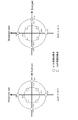
- Example # 3 In the case of (Example # 4), by setting ⁇ to ⁇ ⁇ radians, the phase with poor reception quality is present uniformly. For example, when (example # 3) is assumed and ⁇ is ⁇ radians, there is a point that the reception quality deteriorates once every four slots as shown in FIG. (If the element q in the channel matrix H is present at the points shown in FIGS. 20 and 21, the reception quality is degraded.) As described above, good reception quality can be obtained in the LOS environment. In the above description, the example in which the precoding weight is changed at a 4-slot period has been described. However, the case where the precoding weight is changed at an N-slot period will be described below. When considered in the same manner as in the first embodiment and the above description, the following processing is performed on the symbol number. For symbol number Ni (i is an integer greater than or equal to 0):
- r1 and r2 are expressed as follows.
- Ni i is an integer greater than or equal to 0:
- the phase of these 2N points should exist uniformly. (Because the direct wave phase in each receiver is likely to have a uniform distribution)
- the precoding weight is switched over time, and the switching is regularly performed, so that the LOS environment in which the direct wave is dominant. In this case, it is possible to obtain an effect that the transmission quality is improved as compared with the conventional spatial multiplexing MIMO transmission.
- the configuration of the receiving apparatus is as described in Embodiment 1.
- the configuration of the receiving apparatus has been described by limiting the number of antennas, but the number of antennas has increased. Can also be implemented in the same manner. That is, the number of antennas in the receiving apparatus does not affect the operation and effect of the present embodiment.
- the error correction code is not limited as in the first embodiment.
- the method of changing the precoding weight on the time axis has been described in comparison with the first embodiment.
- the multi-carrier transmission scheme is used, and the frequency axis and frequency -By arranging symbols on the time axis, the same method can be implemented even if the precoding weight is changed.
- symbols other than data symbols for example, pilot symbols (preamble, unique word, etc.), control information symbols, etc. may be arranged in any manner.
- r1 and r2 are expressed as follows.
- Ni i is an integer greater than or equal to 0:
- Expressions (90) to (93) are a real number and q is a complex number.
- Expressions (90) to (93) are expressed as follows. For symbol number Ni (i is an integer greater than or equal to 0):
- the transmission apparatus of the MIMO transmission system transmits a plurality of modulated signals from a plurality of antennas
- the precoding weight is switched over time, and the switching is regularly performed, so that the LOS environment in which the direct wave is dominant.
- the configuration of the receiving apparatus is as described in Embodiment 1.
- the configuration of the receiving apparatus has been described by limiting the number of antennas, but the number of antennas has increased. Can also be implemented in the same manner. That is, the number of antennas in the receiving apparatus does not affect the operation and effect of the present embodiment.
- the error correction code is not limited as in the first embodiment.
- the method of changing the precoding weight on the time axis has been described in comparison with the first embodiment.
- the multi-carrier transmission scheme is used, and the frequency axis and frequency -By arranging symbols on the time axis, the same method can be implemented even if the precoding weight is changed.
- symbols other than data symbols for example, pilot symbols (preamble, unique word, etc.), control information symbols, etc. may be arranged in any manner.
- r1 and r2 are expressed as follows.
- symbol number 2Ni i is an integer greater than or equal to 0:
- Equations (118) to (125) A is a real number and q is a complex number. Equations (118) to (125) are expressed as follows. For symbol number 2Ni (i is an integer greater than or equal to 0):
- ⁇ Condition # 8> is the same as the condition described in Embodiments 1 to 3, but ⁇ Condition # 7> is 2 of q because ⁇ ⁇ ⁇ .
- the solution that does not include ⁇ will have a different solution.
- ⁇ may be set to a certain value, and a requirement for ⁇ needs to be given as a requirement. Therefore, a method for setting ⁇ when ⁇ is 0 radians will be described.
- the transmission apparatus of the MIMO transmission system transmits a plurality of modulated signals from a plurality of antennas
- the precoding weight is switched over time, and the switching is regularly performed, so that the LOS environment in which the direct wave is dominant.
- the configuration of the receiving apparatus is as described in Embodiment 1.
- the configuration of the receiving apparatus has been described by limiting the number of antennas, but the number of antennas has increased. Can also be implemented in the same manner. That is, the number of antennas in the receiving apparatus does not affect the operation and effect of the present embodiment.
- the error correction code is not limited as in the first embodiment.
- the method of changing the precoding weight on the time axis has been described in comparison with the first embodiment.
- the multi-carrier transmission scheme is used, and the frequency axis and frequency -By arranging symbols on the time axis, the same method can be implemented even if the precoding weight is changed.
- symbols other than data symbols for example, pilot symbols (preamble, unique word, etc.), control information symbols, etc. may be arranged in any manner.
- Embodiment 5 In Embodiments 1 to 4, the method of switching the precoding weights regularly has been described, but in the present embodiment, a modified example thereof will be described. In Embodiments 1 to 4, the method of switching the precoding weight regularly as shown in FIG. 6 has been described. In the present embodiment, a method for regularly switching precoding weights different from that in FIG. 6 will be described.
- FIG. 22 shows a diagram relating to a switching method different from that in FIG. 6 in a method of switching four different precoding weights (matrixes).
- four different precoding weights (matrixes) are represented as W1, W2, W3, and W4.
- W1 is a precoding weight (matrix) in Equation (37)
- W2 is a precoding weight (matrix) in Equation (38)
- W3 is a precoding weight (matrix) in Equation (39)
- W4 is Equation (40).
- the unique part is The first cycle 2201, the second cycle 2202, the third cycle 2203,...
- the precoding weight generation unit 2200 receives a signal relating to a weighting method as input, and outputs information 2210 relating to a precoding weight according to the order in each period.
- the weighting / synthesizing unit 600 receives the signal and s1 (t) and s2 (t) as inputs, performs weighting / synthesizing, and outputs z1 (t) and z2 (t).
- FIG. 23 shows a weighted synthesis method with respect to the above-described precoding method.
- 23 differs from FIG. 22 in that a rearrangement unit is arranged after the weighting synthesis unit and signals are rearranged to realize the same method as in FIG. 23, the precoding weight generation unit 2200 inputs the information 315 regarding the weighting process, the precoding weight W1, W2, W3, W4, W1, W2, W3, W4, information precoding weights in the order of ... 2210 is output. Therefore, weighting combining section 600 uses precoding weights in the order of precoding weights W1, W2, W3, W4, W1, W2, W3, W4 , ..., And outputs precoded signals 2300A and 2300B.
- Reordering section 2300 receives precoded signals 2300A and 2300B as input, and outputs the signals after precoding so that the first cycle 2201, the second cycle 2202, and the third cycle 2203 in FIG. Rearrangement is performed for 2300A and 2300B, and z1 (t) and z2 (t) are output.
- the switching cycle of the precoding weight has been described as 4 in order to compare with FIG. 6, but the same can be performed even when the cycle is other than the cycle 4 as in Embodiments 1 to 4. Is possible.
- the values of ⁇ and ⁇ are the same for each slot within the period. However, the values of ⁇ and ⁇ for each slot are described. May be switched.
- the transmission apparatus of the MIMO transmission system transmits a plurality of modulated signals from a plurality of antennas
- the precoding weight is switched over time, and the switching is regularly performed, so that the LOS environment in which the direct wave is dominant.
- the configuration of the receiving apparatus is as described in Embodiment 1.
- the configuration of the receiving apparatus has been described by limiting the number of antennas, but the number of antennas has increased. Can also be implemented in the same manner. That is, the number of antennas in the receiving apparatus does not affect the operation and effect of the present embodiment.
- the error correction code is not limited as in the first embodiment.
- the method of changing the precoding weight on the time axis has been described in comparison with the first embodiment.
- the multi-carrier transmission scheme is used, and the frequency axis and frequency -By arranging symbols on the time axis, the same method can be implemented even if the precoding weight is changed.
- symbols other than data symbols for example, pilot symbols (preamble, unique word, etc.), control information symbols, etc. may be arranged in any manner.
- Embodiment 6 In Embodiments 1 to 4, the method for switching precoding weights regularly has been described, but in this embodiment, the precoding weights are regularly changed again, including the contents described in Embodiments 1 to 4. A method of switching will be described.
- a method for designing a precoding matrix of a spatial multiplexing type 2x2 MIMO system to which precoding without feedback from a communication partner is applied in consideration of the LOS environment will be described.
- FIG. 30 shows a spatial multiplexing type 2 ⁇ 2 MIMO system model to which precoding without feedback from a communication partner is applied.
- the information vector z is encoded and interleaved.
- an encoded bit vector u (p) (u 1 (p), u 2 (p)) is obtained as an interleave output (p is a slot time).
- u i (p) (u i1 (p)..., U ih (p)) (h: number of transmission bits per symbol).
- H (p) is a channel matrix
- n i (p) is an average value 0, and variance ⁇ 2 iid complex Gaussian noise.
- H d (p) is a channel matrix of the direct wave component
- H s (p) is a channel matrix of the scattered wave component. Therefore, the channel matrix H (p) is expressed as follows.
- the channel matrix H d (p) of the direct wave component is a channel matrix regular matrix of the direct wave component because there is a high possibility that the distance between the transmitter and receiver is sufficiently long compared to the transmission antenna interval.
- the channel matrix H d (p) is represented as follows.
- A is a positive real number
- q is a complex number.
- the following describes a precoding matrix design method for a spatially multiplexed 2x2 MIMO system that applies precoding that does not have feedback from the communication partner in consideration of the LOS environment. From the equations (144) and (145), it is difficult to analyze in a state including a scattered wave. Therefore, it is difficult to obtain an appropriate precoding matrix without feedback in a state including a scattered wave. In addition, in the NLOS environment, data reception quality is less degraded than in the LOS environment. Therefore, an appropriate feedback-less precoding matrix design method in LOS environment (a precoding matrix of a precoding method that switches a precoding matrix with time) will be described.
- the precoding matrix is expressed as follows.
- Formula (147) can be expressed as follows.
- Equation (149) when the receiver performs a linear operation such as ZF (zeroforcing) or MMSE (minimum meansquared error), determine the bit transmitted by s 1 (p), s 2 (p) I can't. From this, iterative APP (or iterative Max-log APP) or APP (or Max-log APP) as described in the first embodiment is performed (hereinafter referred to as ML (Maximum Likelihood) operation), and s The log likelihood ratio of each bit transmitted in 1 (p), s 2 (p) is obtained, and decoding in the error correction code is performed. Therefore, a method for designing a precoding matrix without an appropriate feedback in an LOS environment for a receiver that performs ML calculation will be described.
- ML Maximum Likelihood
- a method of switching the precoding matrix regularly with a time period of N slots (hereinafter referred to as a precoding hopping method) is considered.
- the precoding matrix F [i] is expressed as follows.
- time (time) N ⁇ k + i (k is an integer greater than or equal to 0, i 0, 1,..., N ⁇ 1 (i is an integer greater than or equal to 0 and less than or equal to N ⁇ 1)
- ⁇ Condition # 10> In all ⁇ terminals, the number of slots taking the poor reception of s1 is 1 slot or less at N in the time period. Therefore, the log likelihood ratio of bits transmitted in s1 (p) over N-1 slots can be obtained. Similarly, according to ⁇ Condition # 11>, in all ⁇ terminals, the number of slots having the reception poor point of s2 is 1 slot or less at N in the time period. Therefore, the log likelihood ratio of the bits transmitted in s2 (p) over N-1 slots can be obtained.
- the probability density distribution of the phase of the direct wave can be considered as a uniform distribution of [0 2 ⁇ ]. Therefore, the probability density distribution of the phase of q in the equations (151) and (152) can also be considered to be a uniform distribution of [0 2 ⁇ ]. Therefore, in the same LOS environment in which only the phase of q is different, the following conditions are given as conditions for giving the ⁇ terminals as fair a data reception quality as possible.
- the reception bad points of s1 are arranged so as to have a uniform distribution with respect to the phase in N within the time period, and the reception bad points of s2 are set to the phase. However, it is arranged so as to have a uniform distribution.
- Equation (166) may be given ( ⁇ , ⁇ 11 [i] does not change with time (may change)).
- N types of precoding matrices F [i] are expressed as follows with reference to Equation (169).
- 7 ⁇ / 8 may be set to ⁇ 7 ⁇ / 8.
- a precoding hopping method different from (Example # 7) and (Example # 8) in which ⁇ ⁇ 1 in the precoding matrix of Expression (174) and considering the distance point in the complex plane between the reception poor points Think.
- the precoding hopping method of time period N in equation (174) is handled, but at this time, according to ⁇ condition # 14>, reception of s 1 is received at N in the time period by all ⁇ terminals. Slots that take inferiority will be 1 slot or less. Therefore, the log likelihood ratio of bits transmitted in s1 (p) over N-1 slots can be obtained.
- the number of slots having the reception poor point of s2 is 1 slot or less at N in the time period. Therefore, the log likelihood ratio of the bits transmitted in s2 (p) over N-1 slots can be obtained.
- the poor reception points of s1 and s2 are represented as shown in FIG. 35 (a) when ⁇ ⁇ 1.0 and as shown in FIG. 35 (b) when ⁇ > 1.0.
- (i) When ⁇ ⁇ 1.0 When ⁇ ⁇ 1.0, the minimum distance in the complex plane of the reception inferior point is the distance between the reception inferior points # 1 and # 2 (d # 1, # 2 ) and the reception inferior point # 1. And # 3 (d # 1, # 3 ), min ⁇ d # 1, # 2 , d # 1, # 3 ⁇ is expressed. At this time, the relationship between ⁇ and d # 1, # 2 and d # 1, # 3 is shown in FIG. And ⁇ that maximizes min ⁇ d # 1, # 2 , d # 1, # 3 ⁇ is
- ⁇ is suitable for obtaining good data reception quality when the equation (198) or the equation (200) is satisfied.
- the poor reception point of s1 is shown in FIGS. 38A and 38B when ⁇ ⁇ 1.0, and FIGS. 39A and 39B when ⁇ > 1.0.
- the configuration method of N different precoding matrices for the precoding hopping method of time period N has been described.
- F [0], F [1], F [2], ..., F [N-2], F [N-1] are prepared as N different precoding matrices.
- F [0], F [1], F [2],..., F [N-2], F [N-1] are prepared as N different precoding matrices.
- the present embodiment is described by taking the case of the single carrier transmission method as an example, F [0], F [1], F [2],...
- F [N-2], F [N-1] are described in this order.
- the present invention is not limited to this, and N different precoding matrices F [0] generated in the present embodiment are not necessarily limited to this.
- F [1], F [2],..., F [N-2], F [N-1] can be applied to a multicarrier transmission scheme such as an OFDM transmission scheme.
- the precoding weight can be changed by arranging symbols on the frequency axis and the frequency-time axis.
- Example # 5 to Example # 10 are shown based on ⁇ Condition # 10> to ⁇ Condition # 16>.
- a plurality of examples An example may be selected, and a long-period precoding matrix switching method may be realized using the precoding matrix shown in the selected example.
- a long-period precoding matrix switching method is realized using the precoding matrix shown in the selected example.
- a long-period precoding matrix switching method is realized. In this case, it does not necessarily follow from ⁇ Condition # 10> to ⁇ Condition # 16>.
- a transmission apparatus that transmits a modulated signal using a transmission method that regularly switches a precoding matrix transmits information on the precoding matrix, and a reception apparatus uses it for a transmission frame based on the information.
- a method has been described in which regular precoding matrix switching information is obtained, decoding of precoding and detection are performed, a log likelihood ratio of transmission bits is obtained, and then error correction decoding is performed.
- FIG. 40 shows an example of the configuration of the transmission apparatus according to the present embodiment, and the same reference numerals are given to those that operate in the same manner as in FIG.
- the encoder group (4002) receives the transmission bit (4001). At this time, as described in the first embodiment, the encoder group (4002) holds a plurality of error correction code encoding units, and, for example, one encoding is performed based on the frame configuration signal 313. One of the encoders, two encoders, and four encoders will be operated.
- the transmission bit (4001) When one encoder operates, the transmission bit (4001) is encoded to obtain a transmission bit after encoding, and the transmission bit after encoding is distributed to two systems and distributed.
- the encoder group (4002) outputs the bits (4003A) and the distributed bits (4003B).
- the transmission bit (4001) When two encoders operate, the transmission bit (4001) is divided into two (named as divided bits A and B), and the first encoder receives the divided bits A and performs encoding.
- the encoded bits are output as distributed bits (4003A).
- the second encoder receives the divided bits B as input, performs encoding, and outputs the encoded bits as distributed bits (4003B).
- the transmission bit (4001) is divided into four (named as divided bits A, B, C, and D), and the first encoder receives the divided bits A as input. Encoding is performed, and the encoded bit A is output.
- the second encoder receives the divided bits B, performs encoding, and outputs the encoded bits B.
- the third encoder receives the divided bits C, performs encoding, and outputs the encoded bits C.
- the fourth encoder receives the divided bits D, performs encoding, and outputs the encoded bits D. Then, the encoded bits A, B, C, and D are divided into distributed bits (4003A) and distributed bits (4003B).
- the transmission apparatus will support the transmission methods shown in Table 1 (Table 1A and Table 1B) below.
- the modulation scheme supports QPSK, 16QAM, 64QAM, 256QAM, and 1024QAM.
- stream # 1 and stream # 2 can set modulation schemes separately.
- # 1: 256QAM, # 2: 1024QAM is “ This indicates that the modulation method of stream # 1 is 256QAM, and the modulation method of stream # 2 is 1024QAM (others are also expressed in the same manner).
- A, B, and C may all be different codes
- A, B, and C may be different coding rates
- A, B, and C are coding methods having different block sizes. It may be.
- each transmission information is assigned to each mode in which “number of transmission signals”, “modulation method”, “number of encoders”, and “error correction coding method” are defined. Therefore, for example, in the case of “the number of transmission signals: 2”, “modulation method: # 1: 1024QAM, # 2: 1024QAM”, “number of encoders: 4”, and “error correction coding method: C”, the transmission information is 01001101. Set. Then, the transmission device transmits transmission information and transmission data in the frame. When transmitting transmission data, especially when the “number of transmission signals” is 2, the “precoding matrix switching method” is used according to Table 1.
- Table 1 five types of D, E, F, G, and H are prepared as “precoding matrix switching methods”, and any one of these five types is set according to Table 1. .
- -Prepare and implement 5 types of different precoding matrices This is realized by setting five different periods, for example, the period of D is 4, the period of E is 8, and so on. Realize by using both different precoding matrices and different periods. Etc. are considered.
- FIG. 41 shows an example of the frame configuration of the modulation signal transmitted by the transmission apparatus of FIG. 40.
- the transmission apparatus sets a mode for transmitting two modulation signals z1 (t) and z2 (t). It is also possible to set both modes for transmitting one modulated signal.
- a symbol (4100) is a symbol for transmitting “transmission information” shown in Table 1.
- Symbols (4101_1 and 4101_2) are reference (pilot) symbols for channel estimation.
- Symbol (4102_1, 4103_1) is a symbol for data transmission transmitted with modulated signal z1 (t)
- symbol (4102_2, 4103_2) is a symbol for data transmission transmitted with modulated signal z2 (t)
- symbol ( 4102_1) and symbols (4102_2) are transmitted using the same (common) frequency at the same time
- symbols (4103_1) and symbols (4103_2) are transmitted using the same (common) frequency at the same time.
- Symbol (4102_1, 4103_1) and symbol (4102_2, 4103_2) are pre-coded when the method of switching precoding matrices regularly described in Embodiments 1 to 4 and Embodiment 6 is used.
- a symbol (4104) is a symbol for transmitting the “transmission information” shown in Table 1.
- Symbol (4105) is a reference (pilot) symbol for channel estimation.
- Symbols (4106, 4107) are data transmission symbols transmitted with the modulated signal z1 (t). At this time, the number of transmission signals is one for the data transmission symbol transmitted with the modulated signal z1 (t). This means that precoding is not performed.
- the transmission apparatus of FIG. 40 generates and transmits the modulation signal according to the frame configuration of FIG. 41 and Table 1.
- the frame configuration signal 313 includes information related to “number of transmission signals”, “modulation method”, “number of encoders”, and “error correction coding method” set based on Table 1.
- the encoding unit (4002), the mapping units 306A and B, and the weighting synthesis units 308A and B receive the frame configuration signal as input and set the “number of transmission signals”, “modulation scheme”, and “encoder” set based on Table 1 The operation based on “number” and “error correction coding method” is performed. Also, “transmission information” corresponding to the set “number of transmission signals”, “modulation scheme”, “number of encoders”, and “error correction coding method” is transmitted to the receiving apparatus.
- the configuration of the receiving apparatus can be expressed in FIG. 7 as in the first embodiment.
- the difference from the first embodiment is that since the information in Table 1 is shared in advance by the transmission / reception device, the “transmission signal number” even if the transmission device does not transmit the information of the precoding matrix to be switched regularly.
- the transmission apparatus transmits “transmission information” corresponding to “modulation method”, “number of encoders”, and “error correction coding method”, and the reception apparatus obtains this information, so that the pre-switching regularly switched from Table 1. It is that the information of a coding matrix can be obtained. Therefore, in the receiving apparatus of FIG. 7, the control information decoding unit 709 obtains “transmission information” transmitted by the transmitting apparatus of FIG.
- the signal processing unit 711 can perform detection based on the switching pattern of the precoding matrix, and can obtain a reception log likelihood ratio.
- transmission information is set for “number of transmission signals”, “modulation method”, “number of encoders”, and “error correction coding method”, and precoding is performed for this.
- the matrix switching method is set, it is not always necessary to set “transmission information” for “number of transmission signals”, “modulation method”, “number of encoders”, and “error correction coding method”.
- transmission information may be set for “number of transmission signals” and “modulation scheme”, and a precoding matrix switching method may be set for this.
- the “transmission information” and the setting method of the precoding matrix switching method are not limited to those in Tables 1 and 2, but the precoding matrix switching method includes “number of transmission signals”, “modulation scheme”, “sign” If the rules are determined in advance so as to switch based on the transmission parameters such as “number of encoders” and “error correction encoding method” (if the rules determined in advance by the transmitting device and the receiving device are shared) (That is, if the precoding matrix switching method is switched according to one of the transmission parameters (or any one of a plurality of transmission parameters)), the transmission apparatus can obtain information on the precoding matrix switching method. There is no need to transmit, and the receiving device discriminates the information of the transmission parameter, thereby cutting the precoding matrix used by the transmitting device.
- example method can be discriminated, it is possible to perform accurate decoding, the detection.
- Tables 1 and 2 a transmission method that regularly switches the precoding matrix when the number of transmission modulation signals is 2 is used. However, if the number of transmission modulation signals is 2 or more, the transmission method is regularly updated. A transmission method for switching a coding matrix can be applied.
- the transmission apparatus does not transmit information on the precoding switching method and does not include information on the precoding switching method. Information is transmitted, and the receiving apparatus obtains this control information, so that the precoding switching method can be estimated.
- the transmitting apparatus does not transmit the direct information regarding the method for switching the precoding matrix regularly, and the receiving apparatus uses the “regular precoding matrix used by the transmitting apparatus”.
- the method of estimating information related to precoding in “Method of switching” has been described.
- the transmission apparatus does not transmit the direct information regarding the method of switching the precoding matrix regularly, so that it is possible to obtain the effect that the data transmission efficiency is improved accordingly.
- the embodiment for changing the precoding weight in the time axis has been described.
- the present embodiment can be used even when a multicarrier transmission scheme such as OFDM transmission is used.
- Embodiments can be similarly implemented.
- the reception device can perform the precoding switching method by obtaining information on the number of transmission signals transmitted by the transmission device. .
- the transmission device is equipped with a communication / broadcasting device such as a broadcasting station, a base station, an access point, a terminal, a mobile phone, and the like.
- the receiving device is equipped with a communication device such as a television, a radio, a terminal, a personal computer, a mobile phone, an access point, and a base station.
- the transmission device and the reception device in the present invention are devices having a communication function, and the devices provide some interface to a device for executing an application such as a television, a radio, a personal computer, or a mobile phone. It is also conceivable that the connection can be made in such a way that it can be connected.
- the pilot symbol is, for example, a known symbol modulated by using PSK modulation in a transmitter / receiver (or the receiver may know the symbol transmitted by the transmitter by synchronizing the receiver). .), And the receiver uses this symbol to perform frequency synchronization, time synchronization, channel estimation (for each modulated signal) (estimation of CSI (Channel State Information)), signal detection, and the like. Become.
- control information symbol is information (for example, a modulation method, an error correction coding method used for communication, a communication information symbol) that needs to be transmitted to a communication partner in order to realize communication other than data (such as an application).
- This is a symbol for transmitting an error correction coding method coding rate, setting information in an upper layer, and the like.
- the present invention is not limited to Embodiments 1 to 5 above, and can be implemented with various modifications. For example, in the above-described embodiment, the case of performing as a communication device has been described. However, the present invention is not limited to this, and this communication method can also be performed as software.
- the precoding switching method in the method of transmitting two modulated signals from two antennas has been described.
- the present invention is not limited to this, and precoding is performed on four mapped signals.
- a method of generating one modulated signal and transmitting from four antennas that is, a method of generating N modulated signals by performing precoding on N mapped signals and transmitting from N antennas
- a precoding switching method for changing precoding weights can be similarly implemented.
- precoding and “precoding weight” are used, but any name may be used.
- signal processing itself is important. Different data may be transmitted by the streams s1 (t) and s2 (t), or the same data may be transmitted.
- Both the transmitting antenna of the transmitting device and the receiving antenna of the receiving device may be configured by a plurality of antennas.
- a program for executing the communication method may be stored in a ROM (Read Only Memory) in advance and the program may be operated by a CPU (Central Processor Unit).
- a program for executing the communication method is stored in a computer-readable storage medium, the program stored in the storage medium is recorded in a computer RAM (Random Access Memory), and the computer is operated according to the program. You may do it.
- LSI Large Scale Integration
- LSI Large Scale Integration
- IC Integrated Circuit
- system LSI super LSI
- ultra LSI ultra LSI
- circuit integration is not limited to LSI's, and implementation using dedicated circuitry or general purpose processors is also possible.
- An FPGA Field Programmable Gate Array
- reconfigurable processor that can reconfigure the connection and setting of circuit cells inside the LSI may be used.
- Embodiment 8 In this embodiment, an application example of the method for regularly switching the precoding weight described in Embodiments 1 to 4 and Embodiment 6 will be described.
- FIG. 6 is a diagram related to the weighting method (precoding method) in the present embodiment.
- the weighting synthesis unit 600 is a weighting synthesis unit that integrates both the weighting synthesis units 308A and 308B of FIG. is there.
- the stream s1 (t) and the stream s2 (t) correspond to the baseband signals 307A and 307B of FIG. 3, that is, the bases according to the mapping of modulation schemes such as QPSK, 16QAM, and 64QAM. It becomes the in-phase component I and the quadrature component Q of the band signal.
- the stream s1 (t) represents the signal with symbol number u as s1 (u), the signal with symbol number u + 1 as s1 (u + 1), and so on.
- a signal with a symbol number u is represented as s2 (u)
- a signal with a symbol number u + 1 is represented as s2 (u + 1), and so on.
- the weighting synthesis unit 600 receives the baseband signals 307A (s1 (t)) and 307B (s2 (t)) in FIG. 3 and the information 315 relating to the weighting information, and performs a weighting method according to the information 315 relating to the weighting information. Then, the signals 309A (z1 (t)) and 309B (z2 (t)) after the weighted synthesis in FIG. 3 are output.
- z1 (t) and z2 (t) are expressed as follows.
- symbol number 8i (i is an integer greater than or equal to 0):
- k 7.
- the symbol number is described, but the symbol number may be considered as time (time).
- z1 (8i + 7) and z2 (8i + 7) at time 8i + 7 are signals at the same time, and z1 (8i + 7) and z2 (8i + 7) Are transmitted by the transmitting apparatus using the same (common) frequency.
- the matrix multiplied by jX is used as a precoding matrix (see equation (226)), so that the reception poor point has a rotated reception bad point with respect to FIG. 42 (a) (see FIG. 42 (b)). ). (However, the poor reception points in FIGS. 42A and 42B do not overlap. In this way, even if e jX is multiplied, the bad reception points should not be overlapped.
- the precoding matrices F [0] to F [15] are expressed by the following equations.
- precoding matrix of period N is expressed by the following equation with reference to equations (82) to (85).
- N 0, 1, 2,..., N-2
- N-1 i is an integer of 0 or more and N-1 or less.
- a precoding matrix having a period N ⁇ M based on the equation (228) is expressed by the following equation.
- the precoding matrix of F [0] to F [N ⁇ M-1] is generated (the precoding matrix of F [0] to F [N ⁇ M-1] has a period of N ⁇ M You can use them in any order.) For example, when symbol number N ⁇ M ⁇ i, precoding is performed using F [0], and when symbol number N ⁇ M ⁇ i + 1 is performed, precoding is performed using F [1],...
- the precoding matrix is generated in this way, a switching method of a precoding matrix having a large period can be realized, and the position of the reception poor point can be easily changed, which improves the reception quality of data. May lead to
- the precoding matrix of the cycle N ⁇ M is expressed by the equation (229), as described above, the precoding matrix of the cycle N ⁇ M may be expressed by the following equation.
- one characteristic configuration is a non-unitary matrix of ⁇ / 2 radians ⁇
- a unitary matrix may be used. As will be described in detail in the tenth embodiment and the sixteenth embodiment, if N is an odd number in the equations (229) and (230), good data reception is possible. The possibility of obtaining quality increases. (Embodiment 9) In the present embodiment, a method for regularly switching a precoding matrix using a unitary matrix will be described.
- the precoding matrix prepared for period N with reference to equations (82) to (85) is given by It expresses.
- Equation (231) the precoding matrix of Equation (231) can be expressed by the following equation.
- ⁇ condition 19> or ⁇ condition 20> is given in order to arrange the reception poor points so as to have a uniform distribution with respect to the phase on the complex plane.
- ⁇ Condition 19> means that the phase difference is 2 ⁇ / N radians.
- ⁇ Condition 20> means that the phase difference is ⁇ 2 ⁇ / N radians.
- FIG. 44A shows the arrangement in FIG. 44A
- the period N is an even number, considering that the above-described phase at the reception poor point for s1 and the above-mentioned phase at the reception poor point for s2 always have the same value, the period N is an odd number.
- the period N is a small value, for example, N ⁇ 16 or less, the minimum distance of reception poor points in the complex plane can be secured to some extent because the number of reception bad points is small. Therefore, when N ⁇ 16, there is a possibility that the reception quality of data can be ensured even if the number is even.
- N different precoding matrices F [0] generated in the present embodiment are not necessarily limited to this.
- F [1], F [2],..., F [N-2], F [N-1] can be applied to a multicarrier transmission scheme such as an OFDM transmission scheme.
- the precoding weight can be changed by arranging symbols on the frequency axis and the frequency-time axis.
- ⁇ condition # 17> and ⁇ condition # 18> can be replaced with the following conditions. (Consider the period as N.)
- Embodiment 10 (Embodiment 10)
- X is 0,1,2, ..., N-2, N-1 and y is 0,1,2, ..., N-2, N-1 (x and y are 0 or more and N) Integer less than or equal to ⁇ 1), and x ⁇ y.)
- Embodiment 10 (Embodiment 10)
- the precoding matrix prepared for the period 2N is expressed by the following equation.
- ⁇ condition # 24> or ⁇ condition # 25> is set in order to arrange the reception inferior points so as to have a uniform distribution with respect to the phase on the complex plane. give.
- ⁇ Condition 24> means that the phase difference is 2 ⁇ / N radians.
- ⁇ Condition 25> means that the phase difference is ⁇ 2 ⁇ / N radians.
- N is an odd number
- N is a small value, for example, N ⁇ 16 or less
- the minimum distance of reception poor points in the complex plane can be ensured to some extent because the number of reception bad points is small. Therefore, when N ⁇ 16, there is a possibility that the reception quality of data can be ensured even if the number is even.
- the precoding matrices F [0] to F [2N-1] are generated based on the equations (234) and (235) (the precoding matrices F [0] to F [2N-1]) Can be used in any order for period 2N.) For example, precoding is performed using F [0] when the symbol number is 2Ni, precoding is performed using F [1] when the symbol number is 2Ni + 1, and F is performed when the symbol number is 2N ⁇ i + h.
- X is N, N + 1, N + 2,..., 2N-2,2N-1 (x is an integer not less than N and not more than 2N-1), and y is N, N + 1, N + 2 ,..., 2N-2, 2N-1 (y is an integer not less than N and not more than 2N-1), and x ⁇ y.
- the configuration method of 2N different precoding matrices for the precoding hopping method of time period 2N has been described.
- F [0], F [1], F [2], ..., F [2N-2], F [2N-1] are prepared as 2N different precoding matrices.
- the present invention is not necessarily limited to this, and 2N different precoding matrices F [0] generated in the present embodiment , F [1], F [2],..., F [2N-2], F [2N-1] can be applied to a multicarrier transmission scheme such as an OFDM transmission scheme.
- the precoding weight can be changed by arranging symbols on the frequency axis and the frequency-time axis.
- the precoding matrix prepared for period 2N is expressed by the following equation.
- ⁇ > 0 and assume a fixed value (regardless of i). (It is assumed that ⁇ in equation (236) and ⁇ in equation (238) have the same value.)
- ⁇ condition # 31> or ⁇ condition # 32> is set in order to arrange the reception poor points so as to have a uniform distribution with respect to the phase on the complex plane.
- ⁇ Condition 31> means that the phase difference is 2 ⁇ / N radians.
- X is N, N + 1, N + 2,..., 2N-2,2N-1 (x is an integer not less than N and not more than 2N-1), and y is N, N + 1, N + 2 ,..., 2N-2, 2N-1 (y is an integer not less than N and not more than 2N-1), and x ⁇ y.
- the configuration method of 2N different precoding matrices for the precoding hopping method of time period 2N has been described.
- F [0], F [1], F [2], ..., F [2N-2], F [2N-1] are prepared as 2N different precoding matrices.
- the present invention is not necessarily limited to this, and 2N different precoding matrices F [0] generated in the present embodiment , F [1], F [2],..., F [2N-2], F [2N-1] can be applied to a multicarrier transmission scheme such as an OFDM transmission scheme.
- the precoding weight can be changed by arranging symbols on the frequency axis and the frequency-time axis.
- ⁇ condition # 37> or ⁇ condition # 38> is set in order to arrange the reception poor points so as to have a uniform distribution with respect to the phase on the complex plane.
- ⁇ Condition 37> means that the phase difference is 2 ⁇ / N radians.
- ⁇ Condition 38> means that the phase difference is ⁇ 2 ⁇ / N radians.
- ⁇ radians, ⁇ > 0, and ⁇ ⁇ 1 the distance between the reception inferior points of s1 in the complex plane is increased, and reception of s2 is performed. Since the distance between the bad points can be increased, good data reception quality can be obtained.
- ⁇ Condition # 37> and ⁇ Condition # 38> are not necessarily required conditions.
- the configuration method of N different precoding matrices for the precoding hopping method of time period N has been described.
- F [0], F [1], F [2],..., F [N-2], F [N-1] are prepared as N different precoding matrices.
- F [N-2], F [N-1] are described in this order.
- the present invention is not limited to this, and N different precoding matrices F [0] generated in the present embodiment are not necessarily limited to this.
- F [1], F [2],..., F [N-2], F [N-1] can be applied to a multicarrier transmission scheme such as an OFDM transmission scheme.
- the precoding weight can be changed by arranging symbols on the frequency axis and the frequency-time axis.
- ⁇ condition # 35> ⁇ condition # 36> can be replaced with the following conditions. (Consider the period as N.)
- k 0, 1,..., M-2, M-1 (k is an integer from 0 to M-1).
- the precoding matrix is generated in this way, a switching method of a precoding matrix having a large period can be realized, and the position of the reception poor point can be easily changed, which improves the reception quality of data. May lead to Note that the formula (242) of the precoding matrix having a period of 2 ⁇ N ⁇ M may be changed to the following formula.
- the equation (243) of the precoding matrix having a period of 2 ⁇ N ⁇ M may be any one of the equations (245) to (247).
- k 0, 1,..., M-2, M-1 (k is an integer from 0 to M-1).
- k 0, 1,..., M-2, M-1 (k is an integer from 0 to M-1).
- ⁇ condition # 39> and ⁇ condition # 40> may be satisfied.
- mapping units 306A and 306B switch the modulation scheme in the transmission apparatus of FIGS.
- the relationship between the modulation multi-level number of the modulation scheme (number of modulation multi-level: the number of signal points of the modulation scheme on the IQ plane) and the precoding matrix will be described.
- the advantage of the method of switching the precoding matrix regularly is that a good data reception quality can be obtained in the LOS environment as described in the sixth embodiment.
- APP based on computation or Max-log APP
- the effect is great.
- the ML operation greatly affects the circuit scale (computation scale) with the modulation multi-level number of the modulation method. For example, when two signals after precoding are transmitted from two antennas and two modulation signals (signals based on the modulation method before precoding) both use the same modulation method, the modulation method Is QPSK, the number of candidate signal points (received signal points 1101 in FIG.
- ML operation may be used for 256QAM.
- SNR signal-to-noise powerratio
- the receiving device uses linear operations such as MMSE and ZF, as a precoding matrix
- MMSE and ZF linear operations
- either a unitary matrix or a non-unitary matrix may be used as a precoding matrix.
- two signals after precoding are transmitted from two antennas, and the two modulation signals (signals based on the modulation scheme before precoding) are both the same modulation.
- the precoding matrix when the method of switching the precoding matrix regularly is used. If a unitary matrix is used and the unitary matrix is larger than 64 values (or larger than 256 values), if the unitary matrix is used, the circuit scale of the receiving apparatus in any modulation system supported by the communication system. There is a high possibility that it is possible to obtain the effect of obtaining good data reception quality while reducing the signal size.
- the unitary matrix even when the modulation level of the modulation scheme is 64 values or less (or 256 values or less). In consideration of this, if multiple modulation schemes with a modulation multi-level number of 64 or less (or 256 or less) are supported, multiple supported modulation schemes of 64 or less are supported. It is important that there is a case where a non-unitary matrix is used as a precoding matrix when a method of regularly switching the precoding matrix is used in any of the modulation methods.
- N modulation signals (signals based on the modulation method before precoding) all use the same modulation method
- a threshold value ⁇ N is provided for the modulation multi-level number of the modulation method
- the modulation method If multiple modulation schemes with a modulation multi-level number of ⁇ N or less are supported, a method of switching the precoding matrix regularly with any one of the supported modulation schemes of ⁇ N or less is supported.
- a non-unitary matrix is used as the precoding matrix, and in the case of a modulation scheme in which the modulation level of the modulation scheme is larger than ⁇ N
- a modulation scheme in which the modulation level of the modulation scheme is larger than ⁇ N In any modulation system supported by the system, there is a possibility that the effect of obtaining good data reception quality while reducing the circuit scale of the receiving apparatus can be obtained in any modulation system. Get higher.
- the modulation multi-level number of the modulation scheme is equal to or less than ⁇ N
- a non-unitary matrix may always be used as a precoding matrix when a scheme that regularly switches the precoding matrix is used.
- the modulation scheme of N modulation signals transmitted simultaneously is described as being the same modulation scheme. However, in the following, two or more modulation schemes are used in N modulation signals transmitted simultaneously. The case where it exists is demonstrated.
- the threshold of relative 2 a1 + a2 2 ⁇ provided, 2 a1 + a2 ⁇ 2 ⁇
- the present invention is not limited to this.
- 2 a1 + a2 + ⁇ + ai + ⁇ + threshold of 2 beta to aN Provided
- FIG. 47 shows a time-frequency of a transmission signal transmitted by a broadcast station (base station) in a system that regularly switches a precoding matrix using a multicarrier transmission method such as OFDM in this embodiment.
- An example of a frame configuration on the shaft is shown. (The frame configuration is from time $ 1 to time $ T.)
- FIG. 47A shows the frame configuration on the time-frequency axis of the stream s1 described in Embodiment 1 and the like, and FIG. The frame configuration on the time-frequency axis of the stream s2 described in the first embodiment is shown.
- the symbols of the same (sub) carrier in the stream s1 and the stream s2 are transmitted at the same time and the same frequency using a plurality of antennas.
- the (sub) carrier used when OFDM is used is a carrier group #A composed of (sub) carrier a to (sub) carrier a + Na, and (sub) carrier b.
- Carrier group #B composed of (sub) carrier b + Nb
- carrier group #C composed of (sub) carrier c to (sub) carrier c + Nc, composed of (sub) carrier d to (sub) carrier d + Nd It shall be divided by carrier group #D,.
- Each subcarrier group supports a plurality of transmission methods. Here, by supporting a plurality of transmission methods, it is possible to effectively utilize the advantages of each transmission method. For example, in FIGS.
- the carrier group #A uses a spatial multiplexing MIMO transmission scheme or a MIMO transmission scheme with a fixed precoding matrix, and the carrier group #B is regularly precoded. It is assumed that a MIMO transmission method for switching a matrix is used, carrier group #C transmits only stream s1, and carrier group #D transmits using a space-time block code.
- FIG. 48 shows a time-frequency of a transmission signal transmitted by a broadcast station (base station) in a system that regularly switches a precoding matrix using a multicarrier transmission method such as OFDM in this embodiment. 48 shows an example of a frame configuration on the axis, and shows a frame configuration from time $ X to time $ X + T ′, which is different from FIG. In FIG.
- (sub) carriers used when OFDM is used are a carrier group #A composed of (sub) carrier a to (sub) carrier a + Na, and (sub) carrier b.
- Carrier group #B composed of (sub) carrier b + Nb
- carrier group #C composed of (sub) carrier c to (sub) carrier c + Nc, composed of (sub) carrier d to (sub) carrier d + Nd
- carrier group #D It shall be divided by carrier group #D,. 48 differs from FIG. 47 in that there are carrier groups in which the communication method used in FIG. 47 differs from the communication method used in FIG. In FIG.
- carrier group #A is transmitted using a space-time block code
- carrier group #B is assumed to use a MIMO transmission scheme that regularly switches a precoding matrix.
- the carrier group #C uses a MIMO transmission system that regularly switches the precoding matrix
- the carrier group #D transmits only the stream s1.
- FIG. 49 shows a signal processing method when a spatial multiplexing MIMO transmission scheme or a MIMO transmission scheme with a fixed precoding matrix is used, and the same numbers as those in FIG. 6 are given.
- the weighting synthesis unit 600 which is a baseband signal according to a certain modulation method, receives the stream s1 (t) (307A), the stream s2 (t) (307B), and the information 315 regarding the weighting method as input, The modulated signal z1 (t) (309A) and the weighted modulated signal z2 (t) (309B) are output.
- the signal processing of the method # 1 in FIG. 49 is performed. That is, the following processing is performed.
- Expression (250) may be expressed as Expression (251) from the viewpoint of transmission power.
- the information 315 regarding the weighting method indicates a MIMO transmission method in which the precoding matrix is fixed, for example, signal processing of method # 2 in FIG. 49 is performed. That is, the following processing is performed.
- FIG. 50 shows the structure of a modulation signal when a space-time block code is used.
- the space-time block encoding unit (5002) in FIG. 50 receives a baseband signal based on a certain modulation signal.
- the space-time block encoding unit (5002) receives the symbols s1, s2,. Then, as shown in FIG.
- FIG. 52 illustrates an example of a configuration of a transmission device of a broadcast station (base station) in the present embodiment.
- the transmission method determination unit (5205) determines the number of carriers, the modulation method, the error correction method, the coding rate of the error correction code, the transmission method, and the like of each carrier group, and outputs the control signal (5206).
- Modulation signal generation unit # 1 (5201_1) receives information (5200_1) and control signal (5206) as input, and modulates carrier group #A in FIGS. 47 and 48 based on the communication method information of control signal (5206).
- the signal z1 (5202_1) and the modulation signal z2 (5203_1) are output.
- modulation signal generation section # 2 receives information (5200_2) and control signal (5206) as input, and based on the communication method information of control signal (5206), carrier group # in FIG. 47 and FIG. B modulation signal z1 (5202_2) and modulation signal z2 (5203_2) are output.
- modulation signal generation section # 3 receives information (5200_3) and control signal (5206) as input, and based on the communication method information of control signal (5206), carrier group # in FIG. 47 and FIG.
- the C modulation signal z1 (5202_3) and the modulation signal z2 (5203_3) are output.
- modulation signal generation section # 4 receives information (5200_4) and control signal (5206) as input, and based on the communication method information of control signal (5206), carrier group # in FIG. 47 and FIG. D modulation signal z1 (5202_4) and modulation signal z2 (5203_4) are output.
- modulation signal generation unit # 5 receives the information (5200_M) and the control signal (5206), and based on the communication method information of the control signal (5206), the modulation signal z1 of a certain carrier group.
- 5202_M) and the modulation signal z2 (5203_M) are output.
- the OFDM-related processing unit (5207_1) includes a modulation signal z1 (5202_1) of carrier group #A, a modulation signal z1 (5202_2) of carrier group #B, a modulation signal z1 (5202_3) of carrier group #C, and a carrier group #D.
- Modulation signal z1 (5202_4),..., And a modulation signal z1 (5202_M) of a certain carrier group and a control signal (5206) are input, and processing such as rearrangement, inverse Fourier transform, frequency conversion, and amplification is performed.
- the transmission signal (5208_1) is output, and the transmission signal (5208_1) is output as a radio wave from the antenna (5209_1).
- the OFDM system-related processing unit (5207_2) includes a modulation signal z1 (5203_1) of carrier group #A, a modulation signal z2 (5203_2) of carrier group #B, a modulation signal z2 (5203_3) of carrier group #C, and a carrier.
- the modulation signal z2 (5203_M) of a certain carrier group, and the control signal (5206) are input, and rearrangement, inverse Fourier transform, frequency conversion, amplification, etc. Processing is performed and a transmission signal (5208_2) is output, and the transmission signal (5208_2) is output as a radio wave from the antenna (5209_2).
- FIG. 53 shows an example of the configuration of the modulation signal generators # 1 to #M in FIG.
- the error correction encoding unit (5302) receives the information (5300) and the control signal (5301) as input, and sets the error correction encoding method and the error correction encoding rate according to the control signal (5301). Then, error correction encoding is performed, and data (5303) after error correction encoding is output.
- (By setting the error correction coding method and the error correction coding rate for example, when using LDPC code, turbo code, convolutional code, etc., depending on the coding rate, puncturing is performed to realize the coding rate.
- the interleaving unit (5304) receives the data (5303) after error correction coding and the control signal (5301) as input, and the data after error correction coding (5303) according to the information of the interleaving method included in the control signal (5301). ) And rearranged data (5305) is output.
- the mapping unit (5306_1) receives the interleaved data (5305) and the control signal (5301) as input, performs mapping processing according to the modulation scheme information included in the control signal (5301), and generates the baseband signal (5307_1). Output.
- mapping section (5306_2) receives interleaved data (5305) and control signal (5301) as input, performs mapping processing according to the modulation scheme information included in control signal (5301), and performs baseband signal ( 5307_2) is output.
- the signal processing unit (5308) receives the baseband signal (5307_1), the baseband signal (5307_2), and the control signal (5301) as inputs, and a transmission method (here, for example, spatial multiplexing MIMO) included in the control signal (5301). Signal processing based on information of a transmission method, a MIMO method using a fixed precoding matrix, a MIMO method that regularly switches the precoding matrix, a space-time block coding, and a transmission method that transmits only the stream s1) The signal z1 (5309_1) after processing and z2 (5309_2) after signal processing are output.
- a transmission method here, for example, spatial multiplexing MIMO
- the signal processing unit (5308) may not output z2 (5309_2) after the signal processing.
- FIG. 53 shows the configuration in the case where there is one error correction encoding unit.
- the configuration is not limited to this.
- a plurality of encoders may be provided. .
- FIG. 54 shows an example of the configuration of the OFDM scheme-related processing units (5207_1 and 5207_2) in FIG. 52, and the same reference numerals are given to those that operate in the same manner as in FIG.
- Rearranger (5402A) modulates modulated signal z1 (5400_1) of carrier group #A, modulated signal z1 (5400_2) of carrier group #B, modulated signal z1 (5400_3) of carrier group #C, and modulated of carrier group #D.
- the modulation signal z1 (5400_M) of a certain carrier group and the control signal (5403) are input, rearrangement is performed, and rearranged signals 1405A and 1405B are output. 47, FIG. 48, and FIG.
- the carrier group allocation is described as an example of the configuration of aggregated subcarriers. However, the present invention is not limited to this. You may comprise a carrier group. 47, FIG. 48, and FIG. 51, the number of carriers in the carrier group is described as an example that does not change in time, but is not limited thereto. This point will be described later separately.
- FIG. 55 shows an example of details of the frame configuration on the time-frequency axis in the method of setting the transmission method for each carrier group as shown in FIG. 47, FIG. 48, and FIG.
- control information symbols are indicated by 5500, individual control information symbols by 5501, data symbols by 5502, and pilot symbols by 5503.
- FIG. 55A shows the frame configuration of the stream s1 on the time-frequency axis
- FIG. 55B shows the frame configuration of the stream s2 on the time-frequency axis.
- the control information symbol is a symbol for transmitting control information common to the carrier group, and includes a symbol for the transceiver to perform frequency and time synchronization, information on (sub) carrier allocation, and the like. It is assumed that the control control symbol is transmitted only from stream s1 at time $ 1.
- the individual control information symbol is a symbol for transmitting control information for each subcarrier group, and the data symbol transmission scheme, modulation scheme, error correction coding scheme, error correction coding rate, and error correction code. Block size information, pilot symbol insertion method information, pilot symbol transmission power information, and the like. It is assumed that the individual control information symbol is transmitted only from the stream s1 at time $ 1.
- the pilot symbol is used for the receiver to estimate the channel estimation, that is, the fluctuation corresponding to h 11 (t), h 12 (t), h 21 (t), and h 22 (t) in Equation (36). Symbol.
- the pilot symbols use, for example, the PSK transmission method and are configured to have a known pattern in the transceiver.
- the receiving apparatus may use the pilot symbols for frequency offset estimation, phase distortion estimation, and time synchronization.
- FIG. 56 shows an example of the configuration of the receiving apparatus for receiving the modulated signal transmitted by the transmitting apparatus in FIG.
- an OFDM scheme-related processing unit (5600_X) receives a received signal 702_X, performs predetermined processing, and outputs a signal 704_X after signal processing.
- the OFDM scheme-related processing unit (5600_Y) receives the received signal 702_Y, performs predetermined processing, and outputs a signal 704_Y after signal processing.
- Control information decoding section 709 in FIG. 56 receives signal processed signal 704_X and signal processed signal 704_Y as input, extracts control information symbols and individual control information symbols in FIG. 55, and transmits the control information using these symbols. And a control signal 710 containing this information is output.
- the channel fluctuation estimation unit 705_1 of the modulated signal z1 receives the signal 704_X after signal processing and the control signal 710 as input, performs channel estimation in a carrier group (desired carrier group) required by this receiving apparatus, and performs channel estimation The signal 706_1 is output.
- channel fluctuation estimation section 705_2 of modulated signal z2 receives signal processed signal 704_X and control signal 710 as input, and performs channel estimation in a carrier group (desired carrier group) required by this receiving apparatus.
- the channel estimation signal 706_2 is output.
- channel fluctuation estimation section 705_1 of modulated signal z1 receives signal processed signal 704_Y and control signal 710 as input, and performs channel estimation in a carrier group (desired carrier group) required by this receiving apparatus.
- the channel estimation signal 708_1 is output.
- channel fluctuation estimation section 705_2 of modulated signal z2 receives signal processed signal 704_Y and control signal 710 as input, and performs channel estimation in a carrier group (desired carrier group) required by this receiving apparatus.
- the channel estimation signal 708_2 is output.
- the signal processing unit 711 receives the signals 706_1, 706_2, 708_1, 708_2, 704_X, 704_Y and the control signal 710, and transmits the data symbols transmitted in the desired carrier group included in the control signal 710. Based on information such as the system, modulation system, error correction coding system, coding rate of error correction coding, block size of error correction code, etc., demodulation and decoding are performed, and received data 712 is output.
- FIG. 57 shows the configuration of the OFDM system-related processing units (5600_X, 5600_Y) in FIG. 56.
- the frequency conversion unit (5701) receives the received signal (5700) as an input, performs frequency conversion, and performs frequency conversion.
- the signal (5702) is output.
- the Fourier transform unit (5703) receives the signal (5702) after frequency conversion, performs Fourier transform, and outputs a signal (5704) after Fourier transform.
- a “spatial multiplexing MIMO transmission scheme, a MIMO scheme using a fixed precoding matrix, a MIMO scheme that regularly switches a precoding matrix, a space-time block Although the encoding method and the transmission method for transmitting only the stream s1 have been described, the present invention is not limited to this. At this time, the method of FIG.
- the MIMO scheme using a typical precoding matrix is not limited to scheme # 2 in FIG. 49, but may be composed of a fixed precoding matrix. Further, in the present embodiment, the case where the number of antennas of the transmission apparatus is two has been described. However, the present invention is not limited to this. If the transmission method can be selected from the MIMO method using a precoding matrix, the MIMO method that regularly switches the precoding matrix, the space-time block coding, and the transmission method that transmits only the stream s1, the same effect can be obtained. Obtainable.
- FIG. 58 shows a carrier group allocation method different from that in FIGS. 47, 48, and 51.
- 47, FIG. 48, FIG. 51, and FIG. 55 illustrate an example in which the allocation of carrier groups is configured with aggregated subcarriers, but in FIG. 58, carriers in the carrier groups are discretely arranged. It is a feature.
- FIG. 58 shows an example of a frame configuration on the time-frequency axis that is different from FIGS. 47, 48, 51, and 55.
- carrier 1 to carrier H, time $ 1 to time $ K The same structure as that of FIG. 55 is denoted by the same reference numeral.
- FIG. 58 shows a carrier group allocation method different from that in FIGS. 47, 48, and 51.
- 47, FIG. 48, FIG. 51, and FIG. 55 illustrate an example in which the allocation of carrier groups is configured with aggregated subcarriers, but in FIG. 58, carriers in the carrier groups are discretely arranged. It is a feature.
- FIG. 58 shows
- a symbol described as “A” is a symbol of carrier group A
- a symbol described as “B” is a symbol of carrier group B
- the symbol is a symbol of the carrier group C
- a symbol described as “D” is a symbol of the carrier group D.
- the carrier groups can be similarly implemented even if they are arranged discretely in the (sub) carrier direction, and it is not always necessary to use the same carrier in the time axis direction. By performing such an arrangement, it is possible to obtain an effect that time and frequency diversity gain can be obtained.
- control information symbols and the unique control information symbols are arranged at the same time for each carrier group, but may be arranged at different times. Further, the number of (sub) carriers used by the carrier group may be changed with time. (Embodiment 16) In the present embodiment, as in Embodiment 10, a method for regularly switching a precoding matrix using a unitary matrix will be described in the case where N is an odd number.
- the precoding matrix prepared for period 2N is expressed by the following equation.
- ⁇ condition # 49> or ⁇ condition # 50> is set in order to arrange the reception inferior points so as to have a uniform distribution with respect to the phase on the complex plane. give.
- ⁇ Condition 49> means that the phase difference is 2 ⁇ / N radians.
- ⁇ Condition 50> means that the phase difference is ⁇ 2 ⁇ / N radians.
- N when considered in the same manner as in the ninth embodiment, when N is an odd number, the distance between reception poor points in the complex plane is larger than when N is an even number. Is likely to grow.
- N when N is a small value, for example, N ⁇ 16 or less, the minimum distance of reception poor points in the complex plane can be ensured to some extent because the number of reception bad points is small. Therefore, when N ⁇ 16, there is a possibility that the reception quality of data can be ensured even if the number is even.
- the precoding matrices F [0] to F [2N-1] are generated based on the equations (253) and (254) (the precoding matrices F [0] to F [2N-1]) Can be used in any order for period 2N.) For example, precoding is performed using F [0] when the symbol number is 2Ni, precoding is performed using F [1] when the symbol number is 2Ni + 1, and F is performed when the symbol number is 2N ⁇ i + h.
- X is N, N + 1, N + 2,..., 2N-2,2N-1 (x is an integer not less than N and not more than 2N-1), and y is N, N + 1, N + 2 ,..., 2N-2, 2N-1 (y is an integer not less than N and not more than 2N-1), and x ⁇ y.
- the configuration method of 2N different precoding matrices for the precoding hopping method of time period 2N has been described.
- F [0], F [1], F [2], ..., F [2N-2], F [2N-1] are prepared as 2N different precoding matrices.
- the present invention is not necessarily limited to this, and 2N different precoding matrices F [0] generated in the present embodiment , F [1], F [2],..., F [2N-2], F [2N-1] can be applied to a multicarrier transmission scheme such as an OFDM transmission scheme.
- the precoding weight can be changed by arranging symbols on the frequency axis and the frequency-time axis.
- the weighting synthesis unit 600 receives the baseband signals 307A (s1 (t)) and 307B (s2 (t)) in FIG. 3 and the information 315 related to the weighting information, and performs a weighting method according to the information 315 related to the weighting information. Then, the signals 309A (z1 (t)) and 309B (z2 (t)) after the weighted synthesis in FIG. 3 are output.
- z1 (t) and z2 (t) are expressed as follows.
- symbol number 8i (i is an integer greater than or equal to 0):
- k 7.
- the symbol number is described, but the symbol number may be considered as time (time).
- z1 (8i + 7) and z2 (8i + 7) at time 8i + 7 are signals at the same time, and z1 (8i + 7) and z2 (8i + 7) Are transmitted by the transmitter using the same (common) frequency.
- the signal at time T is s1 (T), s2 (T), z1 (T), z2 (T), from some precoding matrix and s1 (T) and s2 (T), z1 (T) and z2 (T) is obtained, and z1 (T) and z2 (T) are transmitted by the transmission device using the same (common) frequency (at the same time (time)).
- signals corresponding to (sub) carrier L and s1, s2, z1, and z2 at time T are s1 (T, L), s2 (T, L), and z1.
- each element in the second row of the matrix on the right side of Expression (190) is set to e jX Is used as a precoding matrix (see equation (226)) so that the reception poor point has a rotated reception bad point with respect to FIG. 42 (a) (see FIG. 42 (b)). .
- the poor reception points in FIGS. 42A and 42B do not overlap. In this way, even if e jX is multiplied, the bad reception points should not be overlapped.
- the precoding matrices F [0] to F [15] are expressed by the following equations.
- precoding matrix of period N is expressed by the following equation with reference to equations (82) to (85).
- N 0, 1, 2,..., N-2, N-1 (i is an integer of 0 or more and N-1 or less).
- a precoding matrix having a period N ⁇ M based on the equation (265) is expressed by the following equation.
- the precoding matrix of F [0] to F [N ⁇ M-1] is generated (the precoding matrix of F [0] to F [N ⁇ M-1] has a period of N ⁇ M You can use them in any order.) For example, when symbol number N ⁇ M ⁇ i, precoding is performed using F [0], and when symbol number N ⁇ M ⁇ i + 1 is performed, precoding is performed using F [1],...
- the precoding matrix is generated in this way, a switching method of a precoding matrix having a large period can be realized, and the position of the reception poor point can be easily changed, which improves the reception quality of data. May lead to
- the precoding matrix of the cycle N ⁇ M is expressed by the equation (266), as described above, the precoding matrix of the cycle N ⁇ M may be expressed by the following equation.
- This scheme has a characteristic configuration when ⁇ / 2 radians ⁇
- ⁇ ⁇ radians.
- Embodiment 18 In the present embodiment, a method for regularly switching a precoding matrix using a unitary matrix based on Embodiment 9 will be described. In the method of switching the precoding matrix regularly with period N as described in the eighth embodiment, the precoding matrix prepared for period N with reference to equations (82) to (85) is given by It expresses.
- the distance between the reception poor points has been described. However, in order to increase the distance between the reception bad points, it is important that the period N is an odd number of 3 or more. This point will be described below.
- ⁇ condition 55> or ⁇ condition 56> is given in order to arrange the reception inferior points so as to have a uniform distribution with respect to the phase on the complex plane.
- FIG. 43 (a) shows the arrangement in FIG. 43
- FIG. 44A shows the arrangement in FIG. 44A
- the period N is an even number, considering that the above-described phase at the reception poor point for s1 and the above-mentioned phase at the reception poor point for s2 always have the same value, the period N is an odd number.
- the period N is a small value, for example, N ⁇ 16 or less, the minimum distance of reception poor points in the complex plane can be secured to some extent because the number of reception bad points is small. Therefore, when N ⁇ 16, there is a possibility that the reception quality of data can be ensured even if the number is even.
- FIG. 94 shows an example of 16QAM signal point arrangement in the in-phase I-quadrature Q plane.
- the coordinates in the in-phase I-orthogonal Q plane are ( ⁇ 3 ⁇ g, 3 ⁇ g), and signal points other than the signal point 9400 are also transmitted.
- the relationship between bits and signal points and the coordinates of the signal points in the in-phase I-quadrature Q plane can be read from FIG.
- FIG. 95 shows an example of QPSK signal point arrangement in the in-phase I-quadrature Q plane.
- the coordinates in the in-phase I-orthogonal Q plane are ( ⁇ 1 ⁇ h, 1 ⁇ h), and the relationship between the bit and signal point to be transmitted for signal points other than the signal point 9500, and
- the coordinates of the signal points in the in-phase I-orthogonal Q plane can be read from FIG.
- ⁇ is
- the signal point arrangement on the IQ plane of 16QAM is as shown in FIG. 94
- the signal point arrangement on the IQ plane of QPSK is as shown in FIG. And g in FIG.
- the set value of ⁇ the set value described above is one effective value, but is not limited to this.
- i in the matrix F [i] ⁇ may be set for each value.
- N different precoding matrices F [0], F [1], generated in the present embodiment, F [2],..., F [N-2], F [N-1] can also be applied to a multicarrier transmission scheme such as an OFDM transmission scheme.
- the precoding weight can be changed by arranging symbols on the frequency axis and the frequency-time axis.
- ⁇ condition # 55> and ⁇ condition # 56> can be replaced with the following conditions. (Consider the period as N.)
- Embodiment 19 a method for regularly switching a precoding matrix using a unitary matrix based on Embodiment 10 will be described.
- the precoding matrix prepared for the period 2N is expressed by the following equation.
- ⁇ condition # 60> or ⁇ condition # 61> is set in order to arrange the reception poor points so as to have a uniform distribution with respect to the phase on the complex plane. give.
- N is a small value, for example, N ⁇ 16 or less
- N ⁇ 16 the minimum distance of reception poor points in the complex plane can be ensured to some extent because the number of reception bad points is small. Therefore, when N ⁇ 16, there is a possibility that the reception quality of data can be ensured even if the number is even.
- the precoding matrices F [0] to F [2N-1] are generated based on the equations (279) and (280) (the precoding matrices F [0] to F [2N-1]) Can be used in any order for period 2N.) For example, precoding is performed using F [0] when the symbol number is 2Ni, precoding is performed using F [1] when the symbol number is 2Ni + 1, and F is performed when the symbol number is 2N ⁇ i + h.
- the signal point arrangement on the IQ plane of 16QAM is as shown in FIG. 60, and the signal point arrangement on the IQ plane of QPSK is as shown in FIG. Then, if g in FIG. 60 is an expression (272), h in FIG. 94 is an expression (273).
- the distance between the reception inferior points of s1 in the complex plane is increased, and between s2 Since the distance between the poor reception points can be increased, good data reception quality can be obtained.
- ⁇ is a fixed value
- ⁇ is a fixed value
- the fixed value of ⁇ in equation (279) and equation (280) The fixed ⁇ value at may be a different value.
- a method of setting the fixed ⁇ value in Equation (279) and the fixed ⁇ value in Equation (280) may be used.
- the set value of ⁇ the set value described above is one effective value, but is not limited to this. For example, as described in the seventeenth embodiment, i in the matrix F [i] ⁇ may be set for each value.
- the precoding weight can be changed by arranging symbols on the frequency axis and the frequency-time axis.
- k 0, 1,..., M-2, M-1 (k is an integer from 0 to M-1).
- the precoding matrix is generated in this way, a switching method of a precoding matrix having a large period can be realized, and the position of the reception poor point can be easily changed, which improves the reception quality of data. May lead to Note that the formula (313) of the precoding matrix having a period of 2 ⁇ N ⁇ M may be changed to the following formula.
- the equation (314) of the precoding matrix having a period of 2 ⁇ N ⁇ M may be any one of the equations (316) to (318).
- k 0, 1,..., M-2, M-1 (k is an integer from 0 to M-1).
- k 0, 1,..., M-2, M-1 (k is an integer from 0 to M-1).
- ⁇ condition # 39> and ⁇ condition # 40> may be satisfied.
Abstract
Priority Applications (13)
| Application Number | Priority Date | Filing Date | Title |
|---|---|---|---|
| JP2013510885A JP5606618B2 (ja) | 2011-04-19 | 2012-04-18 | 中継方法、中継装置 |
| EP18200955.5A EP3451559B1 (fr) | 2011-04-19 | 2012-04-18 | Procédé et dispositif de communication |
| US14/110,783 US8989237B2 (en) | 2011-04-19 | 2012-04-18 | Relay method and relay device |
| CN201280017890.6A CN103503351B (zh) | 2011-04-19 | 2012-04-18 | 接收装置及其接收方法 |
| EP12774709.5A EP2701328B1 (fr) | 2011-04-19 | 2012-04-18 | Procédé et dispositif de communication |
| EP17174756.1A EP3232590B1 (fr) | 2011-04-19 | 2012-04-18 | Procédé et dispositif de communication |
| US14/582,610 US9426631B2 (en) | 2011-04-19 | 2014-12-24 | Relay method and relay device |
| US15/202,924 US9806793B2 (en) | 2011-04-19 | 2016-07-06 | Relay method and relay device |
| US15/617,550 US10044432B2 (en) | 2011-04-19 | 2017-06-08 | Relay method and relay device |
| US16/017,244 US10623084B2 (en) | 2011-04-19 | 2018-06-25 | Relay method and relay device |
| US16/790,358 US11070281B2 (en) | 2011-04-19 | 2020-02-13 | Terminal apparatus and communication scheme |
| US17/243,988 US11658733B2 (en) | 2011-04-19 | 2021-04-29 | Base station and communication scheme executed by a base station |
| US18/123,505 US20230231617A1 (en) | 2011-04-19 | 2023-03-20 | Relay method and relay device |
Applications Claiming Priority (10)
| Application Number | Priority Date | Filing Date | Title |
|---|---|---|---|
| JP2011-093539 | 2011-04-19 | ||
| JP2011093539 | 2011-04-19 | ||
| JP2011102099 | 2011-04-28 | ||
| JP2011-102099 | 2011-04-28 | ||
| JP2011-118453 | 2011-05-26 | ||
| JP2011118453 | 2011-05-26 | ||
| JP2011-140747 | 2011-06-24 | ||
| JP2011140747 | 2011-06-24 | ||
| JP2011-192123 | 2011-09-02 | ||
| JP2011192123 | 2011-09-02 |
Related Child Applications (2)
| Application Number | Title | Priority Date | Filing Date |
|---|---|---|---|
| US14/110,783 A-371-Of-International US8989237B2 (en) | 2011-04-19 | 2012-04-18 | Relay method and relay device |
| US14/582,610 Continuation US9426631B2 (en) | 2011-04-19 | 2014-12-24 | Relay method and relay device |
Publications (1)
| Publication Number | Publication Date |
|---|---|
| WO2012144202A1 true WO2012144202A1 (fr) | 2012-10-26 |
Family
ID=47041334
Family Applications (1)
| Application Number | Title | Priority Date | Filing Date |
|---|---|---|---|
| PCT/JP2012/002676 WO2012144202A1 (fr) | 2011-04-19 | 2012-04-18 | Procédé de relais et dispositif de relais |
Country Status (6)
| Country | Link |
|---|---|
| US (8) | US8989237B2 (fr) |
| EP (4) | EP3035575B1 (fr) |
| JP (6) | JP5606618B2 (fr) |
| CN (2) | CN106100715B (fr) |
| TW (1) | TWI511485B (fr) |
| WO (1) | WO2012144202A1 (fr) |
Cited By (3)
| Publication number | Priority date | Publication date | Assignee | Title |
|---|---|---|---|---|
| CN112468195A (zh) * | 2015-03-23 | 2021-03-09 | Lg 电子株式会社 | 广播信号发送设备和方法以及广播信号接收设备和方法 |
| JP2021122136A (ja) * | 2011-04-19 | 2021-08-26 | サン パテント トラスト | 送信装置及び送信方法 |
| US11463989B2 (en) * | 2020-01-21 | 2022-10-04 | H.M. Electronics, Inc. | Systems and methods for facilitating wireless intercom in a local communications network |
Families Citing this family (25)
| Publication number | Priority date | Publication date | Assignee | Title |
|---|---|---|---|---|
| JP5594002B2 (ja) * | 2010-04-06 | 2014-09-24 | ソニー株式会社 | 画像データ送信装置、画像データ送信方法および画像データ受信装置 |
| JP5578617B2 (ja) | 2010-10-18 | 2014-08-27 | パナソニック インテレクチュアル プロパティ コーポレーション オブ アメリカ | 送信方法、送信装置、受信方法および受信装置 |
| CN103477583B (zh) * | 2011-04-19 | 2016-11-09 | 太阳专利托管公司 | 预编码方法、预编码装置 |
| JP6447911B2 (ja) | 2012-05-22 | 2019-01-09 | サン パテント トラスト | 送信方法、受信方法、送信装置及び受信装置 |
| JP5983111B2 (ja) * | 2012-07-06 | 2016-08-31 | ソニー株式会社 | 受信装置および方法、並びに、プログラム |
| US9374141B2 (en) * | 2012-12-07 | 2016-06-21 | Sun Patent Trust | Signal generation method, transmission device, reception method, and reception device |
| CN106537861B (zh) * | 2014-08-29 | 2020-02-14 | 华为技术有限公司 | 一种数据传输方法和设备 |
| CN104794292B (zh) * | 2015-04-24 | 2018-12-25 | 深圳市国电科技通信有限公司 | 频响曲线实时仿真生成电力线信道的方法 |
| CN108886396B (zh) * | 2016-02-03 | 2021-09-17 | 三星电子株式会社 | 用于配置参考信号和用于生成信道信息的方法和装置 |
| KR102410157B1 (ko) * | 2016-03-17 | 2022-06-17 | 한국전자통신연구원 | Los 환경에서 mimo 사용하여 전송량 증대가 가능한 무선 통신 장치 및 그 방법 |
| TWI612787B (zh) * | 2016-05-02 | 2018-01-21 | 瑞昱半導體股份有限公司 | 最大可能性偵測器 |
| CN105978842A (zh) * | 2016-07-05 | 2016-09-28 | 南京理工大学 | 一种基于部分传输序列的改进型非线性脉冲噪声削减方法 |
| KR102247005B1 (ko) | 2016-08-12 | 2021-04-30 | 텔레호낙티에볼라게트 엘엠 에릭슨(피유비엘) | 더 최적화된 오버헤드를 갖는 멀티-빔 코드북들 |
| WO2018029644A2 (fr) * | 2016-08-12 | 2018-02-15 | Telefonaktiebolaget Lm Ericsson (Publ) | Rétroaction de csi avancée progressive |
| MX2019001567A (es) | 2016-08-12 | 2019-06-10 | Ericsson Telefon Ab L M | Mecanismos de notificacion ricos en informacion de estado de canal de capa 1 y capa 2. |
| EP3497803A1 (fr) | 2016-08-12 | 2019-06-19 | Telefonaktiebolaget LM Ericsson (PUBL) | Livre de codes configurable pour réduction de la surcharge de renvoi de csi avancées |
| WO2018094604A1 (fr) | 2016-11-23 | 2018-05-31 | 广东欧珀移动通信有限公司 | Procédé de traitement de données, et dispositif terminal et dispositif de réseau |
| KR101947263B1 (ko) * | 2017-04-19 | 2019-02-12 | 재단법인 다차원 스마트 아이티 융합시스템 연구단 | 송신기 및 수신기 사이에서 무선 충전을 중계하는 무선 충전 중계 모듈 |
| US10644908B2 (en) * | 2017-08-29 | 2020-05-05 | Cable Laboratories, Inc | System and methods for multi-level signal transmission |
| CN108199752A (zh) * | 2018-01-08 | 2018-06-22 | 哈尔滨工业大学 | 一种低复杂度的双极化卫星mimo信号检测方法 |
| CN108540195B (zh) * | 2018-03-05 | 2019-01-08 | 杭州掌门物联科技有限公司 | 狭窄空间网络中继系统及方法 |
| CN110581719A (zh) * | 2018-06-11 | 2019-12-17 | 中兴通讯股份有限公司 | 一种调度方法、装置及计算机存储介质 |
| CN112385169B (zh) * | 2018-08-02 | 2022-04-12 | 华为技术有限公司 | 频域位置确定方法、装置及设备 |
| CN112910517B (zh) * | 2021-01-19 | 2022-03-29 | 南京邮电大学 | 基于低精度量化的Massive MIMO中继系统下行链路模型构建方法 |
| KR102603640B1 (ko) * | 2021-11-23 | 2023-11-16 | 금오공과대학교 산학협력단 | 듀얼모드 지수변조를 적용한 mimo-sefdm 시스템 |
Citations (9)
| Publication number | Priority date | Publication date | Assignee | Title |
|---|---|---|---|---|
| JP2002111615A (ja) * | 2000-10-03 | 2002-04-12 | Sharp Corp | 放送信号受信システム |
| WO2005050885A1 (fr) | 2003-11-21 | 2005-06-02 | Matsushita Electric Industrial Co., Ltd. | Procede, dispositif, appareil de transmission et systeme de communication multi-antenne |
| WO2008048060A1 (fr) * | 2006-10-18 | 2008-04-24 | Electronics And Telecommunications Research Institute | Procédé de recherche de cellules par tdm pour système ofdm |
| WO2010084553A1 (fr) * | 2009-01-23 | 2010-07-29 | パナソニック株式会社 | Appareil de relais sans fil et système de relais sans fil |
| JP2011093539A (ja) | 2009-10-27 | 2011-05-12 | Yoshino Kogyosho Co Ltd | 液体噴出器 |
| JP2011102099A (ja) | 2009-11-11 | 2011-05-26 | Autoliv Development Ab | シートベルト装置 |
| JP2011118453A (ja) | 2009-11-30 | 2011-06-16 | Toshiba Corp | 電子機器、及び機能設定データ設定方法 |
| JP2011140747A (ja) | 2010-01-05 | 2011-07-21 | Senyo Shokai:Kk | 移動間仕切り構造 |
| JP2011192123A (ja) | 2010-03-16 | 2011-09-29 | Yanmar Co Ltd | 薬剤散布管理システム |
Family Cites Families (62)
| Publication number | Priority date | Publication date | Assignee | Title |
|---|---|---|---|---|
| JPS5342043A (en) | 1976-09-28 | 1978-04-17 | Nec Corp | Optical multichannel system |
| US6954482B2 (en) * | 2003-04-24 | 2005-10-11 | Bae Systems Information And Electronic Systems Integration Inc. | Soft-decision trellis-coded differential frequency-hopped spread spectrum (DFHSS) |
| JP4884722B2 (ja) | 2005-03-31 | 2012-02-29 | 株式会社エヌ・ティ・ティ・ドコモ | 無線通信装置及び無線通信方法 |
| KR101124932B1 (ko) * | 2005-05-30 | 2012-03-28 | 삼성전자주식회사 | 어레이 안테나를 이용하는 이동 통신 시스템에서의 데이터송/수신 장치 및 방법 |
| JP2007228029A (ja) | 2006-02-21 | 2007-09-06 | Fujitsu Ltd | 無線通信システム及び受信装置 |
| CN101273548B (zh) * | 2006-06-20 | 2010-12-08 | 华为技术有限公司 | 预编码mimo-ofdm系统中降低反馈信息开销的方法 |
| WO2008004835A2 (fr) * | 2006-07-06 | 2008-01-10 | Lg Electronics Inc. | Procédé et appareil permettant de corriger des erreurs dans un système de communication à plusieurs sous-porteuses au moyen de plusieurs antennes |
| JP2008092062A (ja) * | 2006-09-29 | 2008-04-17 | Kddi Corp | ビーム制御装置、アレーアンテナシステムおよび無線装置 |
| US8503560B2 (en) | 2006-10-02 | 2013-08-06 | Samsung Electronics Co., Ltd | System and method for performing precoding in a wireless communication system |
| US20100015927A1 (en) | 2006-10-24 | 2010-01-21 | Panasonic Corporation | Radio communication device and radio communication method |
| US9106296B2 (en) | 2006-12-19 | 2015-08-11 | Qualcomm Incorporated | Beam space time coding and transmit diversity |
| WO2008088066A1 (fr) | 2007-01-19 | 2008-07-24 | Panasonic Corporation | Dispositif de transmission à plusieurs antennes, dispositif de réception à plusieurs antennes, procédé de transmission à plusieurs antennes, procédé de réception à plusieurs antennes, dispositif terminal et dispositif de poste de base |
| CN101578779A (zh) | 2007-01-19 | 2009-11-11 | 松下电器产业株式会社 | 多天线发送装置、多天线接收装置、多天线发送方法、多天线接收方法、终端装置以及基站装置 |
| AU2008213683B2 (en) | 2007-02-06 | 2011-02-17 | Qualcomm Incorporated | Apparatus and method for MIMO transmission with explicit and implicit cyclic delays |
| US8780771B2 (en) * | 2007-02-06 | 2014-07-15 | Qualcomm Incorporated | Cyclic delay diversity and precoding for wireless communication |
| US8451915B2 (en) * | 2007-03-21 | 2013-05-28 | Samsung Electronics Co., Ltd. | Efficient uplink feedback in a wireless communication system |
| US8290079B2 (en) | 2007-04-19 | 2012-10-16 | Interdigital Technology Corporation | Method and apparatus for precoding validation in wireless communications |
| JPWO2008132825A1 (ja) | 2007-04-20 | 2010-07-22 | パナソニック株式会社 | 無線送信装置、無線受信装置およびブロック構成方法 |
| CN101359953B (zh) * | 2007-08-01 | 2013-01-16 | 中兴通讯股份有限公司 | Td-scdma系统室外宏蜂窝中应用多输入多输出技术的方法 |
| JP2009055228A (ja) | 2007-08-24 | 2009-03-12 | Sony Corp | 無線通信システム、無線通信装置及び無線通信方法 |
| CN101378299B (zh) * | 2007-08-28 | 2012-05-09 | 中兴通讯股份有限公司 | 一种基于空频编码的发射分集方法 |
| KR20090025129A (ko) * | 2007-09-05 | 2009-03-10 | 엘지전자 주식회사 | 다중 안테나 통신 시스템에서 다중 부호어를 송수신하는방법 |
| KR101098096B1 (ko) * | 2007-09-06 | 2011-12-26 | 후지쯔 가부시끼가이샤 | 적응 멀티 안테나를 이용하는 이동체 통신 시스템 |
| KR20090030200A (ko) | 2007-09-19 | 2009-03-24 | 엘지전자 주식회사 | 위상천이 기반의 프리코딩을 이용한 데이터 송수신 방법 및이를 지원하는 송수신기 |
| US20090110114A1 (en) * | 2007-10-26 | 2009-04-30 | Eko Nugroho Onggosanusi | Open-Loop MIMO Scheme and Signaling Support for Wireless Networks |
| US20090122857A1 (en) * | 2007-11-09 | 2009-05-14 | Interdigital Patent Holdings, Inc. | Method and apparatus for performing rank overriding in long term evolution networks |
| JP2009171155A (ja) | 2008-01-15 | 2009-07-30 | Panasonic Corp | マルチアンテナ送信方法及びマルチアンテナ送信装置 |
| KR101349831B1 (ko) * | 2008-03-23 | 2014-01-09 | 엘지전자 주식회사 | 피드백 오버헤드 감소를 위한 신호 전송 방법 및 이를 위한피드백 정보 전송 방법 |
| US8233926B2 (en) * | 2008-05-22 | 2012-07-31 | Futurewei Technologies, Inc. | Spatial mode adaptation at the cell edge using interferer spatial correlation |
| JP5366946B2 (ja) | 2008-06-17 | 2013-12-11 | パナソニック株式会社 | 無線送信装置及び無線送信方法 |
| EP2141825A1 (fr) * | 2008-06-30 | 2010-01-06 | Alcatel, Lucent | Procédé pour réduire l'interférence spatiale intra-cellulaire dans un réseau cellulaire mobile |
| US8654752B2 (en) | 2008-08-05 | 2014-02-18 | Panasonic Corporation | Radio communication device and radio communication method |
| KR20100019948A (ko) * | 2008-08-11 | 2010-02-19 | 엘지전자 주식회사 | 공간 다중화 기법을 이용한 데이터 전송방법 |
| KR101508704B1 (ko) * | 2008-08-19 | 2015-04-03 | 한국과학기술원 | 다중안테나 시스템에서 송ㆍ수신 장치 및 방법 |
| US8737509B2 (en) | 2009-01-07 | 2014-05-27 | Panasonic Corporation | Wireless communication apparatus, wireless communication system and wireless communication method |
| JP5263739B2 (ja) * | 2009-01-21 | 2013-08-14 | 独立行政法人情報通信研究機構 | ビームフォーミング技術を利用した無線通信方法及び無線通信システム |
| US8830918B2 (en) * | 2009-03-16 | 2014-09-09 | Interdigital Patent Holdings, Inc. | Method and apparatus for performing uplink transmit diversity |
| JP5598771B2 (ja) * | 2009-04-17 | 2014-10-01 | マーベル ワールド トレード リミテッド | セグメント化ビーム形成 |
| WO2010122818A1 (fr) | 2009-04-24 | 2010-10-28 | シャープ株式会社 | Système de radiocommunication, dispositif de radiocommunication, et procédé de radiocommunication |
| WO2010122749A1 (fr) | 2009-04-24 | 2010-10-28 | シャープ株式会社 | Système de communication, appareil de communication et procédé de communication |
| EP2445260B1 (fr) | 2009-06-16 | 2016-04-06 | Sharp Kabushiki Kaisha | Appareil transmetteur, appareil récepteur, système de communication et procédé de communication |
| JP2011004161A (ja) | 2009-06-18 | 2011-01-06 | Sharp Corp | 通信システム、通信装置および通信方法 |
| JP2011004212A (ja) | 2009-06-19 | 2011-01-06 | Sharp Corp | 送信装置、受信装置、通信システムおよび通信方法 |
| EP2479910A4 (fr) * | 2009-12-03 | 2016-11-23 | Lg Electronics Inc | Procédé et appareil permettant une transmission en mode contention efficace dans un système de communication sans fil |
| JP2011234282A (ja) * | 2010-04-30 | 2011-11-17 | Sharp Corp | 通信システム、送信装置、受信装置、プログラム、及びプロセッサ |
| CN101860970A (zh) * | 2010-05-04 | 2010-10-13 | 中兴通讯股份有限公司 | 控制信息的传输方法、系统以及装置 |
| CN104967501B (zh) * | 2010-06-17 | 2018-07-24 | 太阳专利托管公司 | 发送方法、发送装置、接收方法及接收装置 |
| JP5623248B2 (ja) * | 2010-09-10 | 2014-11-12 | パナソニックインテレクチュアル プロパティ コーポレーション オブアメリカPanasonic Intellectual Property Corporation of America | 送信方法、送信装置、受信方法および受信装置 |
| CN103141053B (zh) | 2010-10-01 | 2015-10-21 | 交互数字专利控股公司 | 用于在多个天线上传送导频的方法和设备 |
| JP5578617B2 (ja) * | 2010-10-18 | 2014-08-27 | パナソニック インテレクチュアル プロパティ コーポレーション オブ アメリカ | 送信方法、送信装置、受信方法および受信装置 |
| US9059756B2 (en) * | 2010-11-09 | 2015-06-16 | Qualcomm Incorporated | Using precoding vector switching in uplink shared channel |
| WO2012114698A1 (fr) * | 2011-02-21 | 2012-08-30 | パナソニック株式会社 | Procédé de précodage et dispositif de précodage |
| JP5991572B2 (ja) * | 2011-02-28 | 2016-09-14 | サン パテント トラスト | 送信方法および送信装置 |
| CN106100715B (zh) * | 2011-04-19 | 2019-12-17 | 太阳专利托管公司 | 接收装置及其接收方法 |
| US20120300877A1 (en) * | 2011-05-27 | 2012-11-29 | Yutaka Murakami | Precoding method, transmitting device, and receiving device |
| US9031018B2 (en) | 2011-11-15 | 2015-05-12 | Telefonaktiebolaget L M Ericsson (Publ.) | Methods selecting modulation/coding schemes mapped to multiple MIMO layers and related user equipment |
| US8638789B1 (en) * | 2012-05-04 | 2014-01-28 | Google Inc. | Optimal multicast forwarding in OpenFlow based networks |
| EP2838219A1 (fr) | 2013-07-05 | 2015-02-18 | Samsung Electronics Co., Ltd | Transmetteur et procédé de transmission de signal associé |
| WO2016015260A1 (fr) | 2014-07-30 | 2016-02-04 | 华为技术有限公司 | Procédé de mesure de qualité de canal en liaison descendante, extrémité émettrice, extrémité réceptrice et système |
| WO2016091905A1 (fr) | 2014-12-12 | 2016-06-16 | Sony Corporation | Émetteur et récepteur utilisant un groupage de canaux |
| KR102040625B1 (ko) | 2015-03-09 | 2019-11-05 | 엘지전자 주식회사 | 방송 신호 송신 장치, 방송 신호 수신 장치, 방송 신호 송신 방법, 및 방송 신호 수신 방법 |
| KR102615658B1 (ko) | 2015-06-22 | 2023-12-20 | 삼성전자주식회사 | 다중 사용자 중첩 전송 방법 및 장치 |
-
2012
- 2012-04-18 CN CN201610398411.XA patent/CN106100715B/zh active Active
- 2012-04-18 US US14/110,783 patent/US8989237B2/en active Active
- 2012-04-18 JP JP2013510885A patent/JP5606618B2/ja active Active
- 2012-04-18 EP EP16151067.2A patent/EP3035575B1/fr active Active
- 2012-04-18 EP EP17174756.1A patent/EP3232590B1/fr active Active
- 2012-04-18 EP EP12774709.5A patent/EP2701328B1/fr active Active
- 2012-04-18 CN CN201280017890.6A patent/CN103503351B/zh active Active
- 2012-04-18 WO PCT/JP2012/002676 patent/WO2012144202A1/fr active Application Filing
- 2012-04-18 EP EP18200955.5A patent/EP3451559B1/fr active Active
- 2012-04-19 TW TW101113939A patent/TWI511485B/zh active
-
2014
- 2014-08-26 JP JP2014171318A patent/JP2015039173A/ja active Pending
- 2014-12-24 US US14/582,610 patent/US9426631B2/en active Active
-
2016
- 2016-02-17 JP JP2016028346A patent/JP6308443B2/ja active Active
- 2016-07-06 US US15/202,924 patent/US9806793B2/en active Active
-
2017
- 2017-06-08 US US15/617,550 patent/US10044432B2/en active Active
-
2018
- 2018-03-01 JP JP2018036396A patent/JP6555604B2/ja active Active
- 2018-06-25 US US16/017,244 patent/US10623084B2/en active Active
-
2019
- 2019-06-20 JP JP2019114350A patent/JP6890277B2/ja active Active
-
2020
- 2020-02-13 US US16/790,358 patent/US11070281B2/en active Active
-
2021
- 2021-04-29 US US17/243,988 patent/US11658733B2/en active Active
- 2021-04-30 JP JP2021077032A patent/JP7378094B2/ja active Active
-
2023
- 2023-03-20 US US18/123,505 patent/US20230231617A1/en active Pending
Patent Citations (9)
| Publication number | Priority date | Publication date | Assignee | Title |
|---|---|---|---|---|
| JP2002111615A (ja) * | 2000-10-03 | 2002-04-12 | Sharp Corp | 放送信号受信システム |
| WO2005050885A1 (fr) | 2003-11-21 | 2005-06-02 | Matsushita Electric Industrial Co., Ltd. | Procede, dispositif, appareil de transmission et systeme de communication multi-antenne |
| WO2008048060A1 (fr) * | 2006-10-18 | 2008-04-24 | Electronics And Telecommunications Research Institute | Procédé de recherche de cellules par tdm pour système ofdm |
| WO2010084553A1 (fr) * | 2009-01-23 | 2010-07-29 | パナソニック株式会社 | Appareil de relais sans fil et système de relais sans fil |
| JP2011093539A (ja) | 2009-10-27 | 2011-05-12 | Yoshino Kogyosho Co Ltd | 液体噴出器 |
| JP2011102099A (ja) | 2009-11-11 | 2011-05-26 | Autoliv Development Ab | シートベルト装置 |
| JP2011118453A (ja) | 2009-11-30 | 2011-06-16 | Toshiba Corp | 電子機器、及び機能設定データ設定方法 |
| JP2011140747A (ja) | 2010-01-05 | 2011-07-21 | Senyo Shokai:Kk | 移動間仕切り構造 |
| JP2011192123A (ja) | 2010-03-16 | 2011-09-29 | Yanmar Co Ltd | 薬剤散布管理システム |
Non-Patent Citations (15)
| Title |
|---|
| "A tutorial on 'parallel concatenated (Turbo) coding', Turbo (iterative) decoding' and related topics", THE INSTITUTE OF ELECTRONICS, INFORMATION, AND COMMUNICATION ENGINEERS, TECHNICAL REPORT IT, pages 98 - 51 |
| "Achieving near-capacity on a multiple-antenna channel", IEEE TRANSACTION ON COMMUNICATIONS, vol. 51, no. 3, March 2003 (2003-03-01), pages 389 - 399 |
| "Advanced signal processing for PLCs: Wavelet-OFDM", PROC. OF IEEE INTERNATIONAL SYMPOSIUM ON ISPLC 2008, 2008, pages 187 - 192 |
| "BER performance evaluation in 2 x 2 MIMO spatial multiplexing systems under Rician fading channels", IEICE TRANS. FUNDAMENTALS, vol. E91-A, no. 10, October 2008 (2008-10-01), pages 2798 - 2807 |
| "DVB Document A122, Framing structure, channel coding and modulation for a second generation digital terrestrial television broadcasting system", DVB-T2, June 2008 (2008-06-01) |
| "Likelihood function for QR-MLD suitable for soft-decision turbo decoding and its performance", IEICE TRANS. COMMUN., vol. E88-B, no. 1, January 2004 (2004-01-01), pages 47 - 57 |
| "Performance analysis and design optimization of LDPC-coded MIMO OFDM systems", IEEE TRANS. SIGNAL PROCESSING, vol. 52, no. 2, February 2004 (2004-02-01), pages 348 - 361 |
| "Second generation framing structure, channel coding and modulation systems for broadcasting, interactive services, news gathering and other broadband satellite applications", ETSI EN 302 307, vol. 1.1, no. 2, June 2006 (2006-06-01) |
| "Turbo space-time codes with time varying linear transformations", IEEE TRANS. WIRELESS COMMUNICATIONS, vol. 6, no. 2, February 2007 (2007-02-01), pages 486 - 493 |
| D. J. C. MACKAY: "Good error-correcting codes based on very sparse matrices", IEEE TRANS. INFORM. THEORY, vol. 45, no. 2, March 1999 (1999-03-01), pages 399 - 431 |
| D. J. LOVE; R. W. HEATH, JR.: "Limited feedback unitary precoding for spatial multiplexing systems", IEEE TRANS. INF. THEORY, vol. 51, no. 8, August 2005 (2005-08-01), pages 2967 - 2976 |
| L. VANGELISTA; N. BENVENUTO; S. TOMASIN: "Key technologies for next-generation terrestrial digital television standard DVB-T2", IEEE COMMUN. MAGAZINE, vol. 47, no. 10, October 2009 (2009-10-01), pages 146 - 153 |
| R. G. GALLAGER: "Low-density parity-check codes", IRE TRANS. INFORM. THEORY, vol. IT-8, 1962, pages 21 - 28 |
| T. OHGANE; T. NISHIMURA; Y. OGAWA: "Application of space division multiplexing and those performance in a MIMO channel", IEICE TRANS. COMMUN., vol. E88-B, no. 5, May 2005 (2005-05-01), pages 1843 - 1851 |
| Y.-L. UENG; C.-C. CHENG: "A fast-convergence decoding method and memory-efficient VLSI decoder architecture for irregular LDPC codes in the IEEE 80216e standards", IEEE VTC-2007 FALL, 2007, pages 1255 - 1259 |
Cited By (6)
| Publication number | Priority date | Publication date | Assignee | Title |
|---|---|---|---|---|
| JP2021122136A (ja) * | 2011-04-19 | 2021-08-26 | サン パテント トラスト | 送信装置及び送信方法 |
| JP7378094B2 (ja) | 2011-04-19 | 2023-11-13 | サン パテント トラスト | 受信装置、受信方法および集積回路 |
| CN112468195A (zh) * | 2015-03-23 | 2021-03-09 | Lg 电子株式会社 | 广播信号发送设备和方法以及广播信号接收设备和方法 |
| CN112468195B (zh) * | 2015-03-23 | 2023-04-28 | Lg 电子株式会社 | 广播信号发送设备和方法以及广播信号接收设备和方法 |
| US11463989B2 (en) * | 2020-01-21 | 2022-10-04 | H.M. Electronics, Inc. | Systems and methods for facilitating wireless intercom in a local communications network |
| US11812448B2 (en) | 2020-01-21 | 2023-11-07 | H.M. Electronics, Inc. | Systems and methods for facilitating wireless intercom in a local communications network |
Also Published As
Similar Documents
| Publication | Publication Date | Title |
|---|---|---|
| JP6555604B2 (ja) | 中継方法、中継装置 | |
| JP6607466B2 (ja) | 信号生成方法及び信号生成装置 | |
| JP6562280B2 (ja) | プリコーディング方法、送信装置 | |
| JP6422065B2 (ja) | プリコーディング方法、プリコーディング装置 | |
| WO2012114698A1 (fr) | Procédé de précodage et dispositif de précodage |
Legal Events
| Date | Code | Title | Description |
|---|---|---|---|
| 121 | Ep: the epo has been informed by wipo that ep was designated in this application |
Ref document number: 12774709 Country of ref document: EP Kind code of ref document: A1 |
|
| ENP | Entry into the national phase |
Ref document number: 2013510885 Country of ref document: JP Kind code of ref document: A |
|
| WWE | Wipo information: entry into national phase |
Ref document number: 14110783 Country of ref document: US |
|
| WWE | Wipo information: entry into national phase |
Ref document number: 2012774709 Country of ref document: EP |
|
| NENP | Non-entry into the national phase |
Ref country code: DE |