WO2012144146A1 - 情報記録媒体用読取ラベルとその情報記録方法 - Google Patents
情報記録媒体用読取ラベルとその情報記録方法 Download PDFInfo
- Publication number
- WO2012144146A1 WO2012144146A1 PCT/JP2012/002377 JP2012002377W WO2012144146A1 WO 2012144146 A1 WO2012144146 A1 WO 2012144146A1 JP 2012002377 W JP2012002377 W JP 2012002377W WO 2012144146 A1 WO2012144146 A1 WO 2012144146A1
- Authority
- WO
- WIPO (PCT)
- Prior art keywords
- film layer
- information recording
- metal film
- recording medium
- label
- Prior art date
Links
Images


Classifications
-
- G—PHYSICS
- G06—COMPUTING; CALCULATING OR COUNTING
- G06K—GRAPHICAL DATA READING; PRESENTATION OF DATA; RECORD CARRIERS; HANDLING RECORD CARRIERS
- G06K19/00—Record carriers for use with machines and with at least a part designed to carry digital markings
- G06K19/06—Record carriers for use with machines and with at least a part designed to carry digital markings characterised by the kind of the digital marking, e.g. shape, nature, code
- G06K19/06009—Record carriers for use with machines and with at least a part designed to carry digital markings characterised by the kind of the digital marking, e.g. shape, nature, code with optically detectable marking
- G06K19/06046—Constructional details
-
- B—PERFORMING OPERATIONS; TRANSPORTING
- B41—PRINTING; LINING MACHINES; TYPEWRITERS; STAMPS
- B41M—PRINTING, DUPLICATING, MARKING, OR COPYING PROCESSES; COLOUR PRINTING
- B41M5/00—Duplicating or marking methods; Sheet materials for use therein
- B41M5/24—Ablative recording, e.g. by burning marks; Spark recording
Definitions
- the present invention relates to a read label for an information recording medium adhered to various base materials and an information recording method thereof.
- FIG. 10 shows a cross-sectional view of a conventional reading label for an information recording medium.
- the read label for the information recording medium includes an adhesive layer 3a provided on the various base materials 2a, a pigment layer 17a provided on the adhesive layer 3a, and an upper surface of the pigment layer 17a.
- the protective film layer 5a provided on the laser marking layer 18a.
- the laser marking layer 18a is irradiated with a laser beam 7a from a laser irradiation apparatus such as a carbon dioxide laser or a YAG laser to form a color developing layer 19a.
- a laser irradiation apparatus such as a carbon dioxide laser or a YAG laser
- the laser marking layer 18a is colored by irradiating a desired marking position with the laser beam 7a emitted from the laser irradiation device, and becomes a coloring layer 19a.
- the laser beam 7a to be used is selected depending on the material of the laser marking layer 18a.
- the color marking layer 19a is identified and discriminated by a color difference from the pigment layer 17a existing below the laser marking layer 18a, and information is read (for example, the following patent document similar to this is referred to 1 and Patent Document 2 exist).
- the contrast of the color forming layer 19a when dirt or the like adheres to the protective film layer 5a is, for example, a barcode on which information is recorded. This is difficult to identify, and causes a malfunction or detection error of the reading apparatus. In other words, in the case of contamination or the like, the contrast is difficult to be obtained only by the color difference, so that there is a problem that the reading reliability is lowered. Accordingly, an object of the present invention is to improve reading reliability.
- the information recording medium reading label of the present invention includes an adhesive layer, a metal film layer provided in contact with the surface side of the adhesive layer, and a surface side of the metal film layer.
- a protective film layer having translucency Provided with a protective film layer having translucency provided; The thickness of the adhesive layer and the protective film layer having translucency is made larger than the thickness of the metal film layer, and a part of the metal film layer is removed by evaporation from the metal film layer. A transpiration removing section is provided, thereby achieving the intended purpose.
- the information recording method of the reading label for an information recording medium of the present invention transcribes and removes a part of the metal film layer by irradiating the metal film layer with a laser beam from the translucent protective film layer side.
- the intended purpose is achieved by forming the transpiration removal portion.
- Sectional drawing of the reading label for information recording media in Embodiment 1 of this invention Sectional drawing which shows laser processing in the manufacturing process of the reading label for information recording media in Embodiment 1 of this invention
- Sectional drawing of the film for foil printing in Embodiment 2 of this invention Sectional drawing which shows manufacture of the read label for information recording media from the film for foil printing in Embodiment 2 of this invention
- Sectional drawing which shows the method of reading the reading label for information recording media in Embodiment 4 of this invention The figure which shows the state which formed the barcode in the reading label for information recording media in Embodiment 4 of this invention
- the perspective view which shows the state which formed the barcode in the reading label for information recording media in Embodiment 4 of this invention
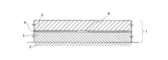
- FIG. 1 is a cross-sectional view of an information recording medium reading label according to Embodiment 1 of the present invention.
- FIG. 2 is a sectional view showing laser processing in the manufacturing process of the reading label for the information recording medium in the first embodiment of the present invention.
- FIG. 3 shows another sectional view showing the read label for the information recording medium in the first embodiment of the present invention.
- the information recording medium reading label and the information recording method thereof relate to an information recording medium reading label on which the information is recorded and the information recording method thereof.
- a reading label for an information recording medium attached to the base substrate and an information recording method thereof will be described using the surface of the device or the object itself or the surface of the container in which the device or the object is stored as a base substrate.
- an information recording medium reading label 1 includes an adhesive layer 3 adhered on a base substrate 2 of various devices, a metal film layer 4 provided on the surface, and a transparent layer provided on the surface.
- the protective film layer 5 is made of light.
- the feature of the present embodiment is that the metal film layer 4 is evaporated without forming the information recording portion 6 on the base substrate 2 to which the protective film layer 5 and the label as an information recording medium are attached. It is.
- the metal film layer 4 is formed on the adhesive layer 3 having a thickness sufficiently larger than the metal film layer 4, for example, 10 times or more the thickness of the metal layer film 4.
- transpiration refers to the heat work in a small area of the metal film layer 4 as a target object by laser light irradiation with respect to the metal film layer 4 which is considerably thinner than the protective film layer 5 and the adhesive layer 3. Is concentrated to increase the energy density, thereby evaporating the metal film layer 4 in the area.
- the metal film layer 4 evaporated and vaporized can be accommodated in the adhesive layer 3. That is, at the time of laser light irradiation, the laser light is transmitted through the light-transmitting protective film layer 5, evaporates the metal film layer 4, and further softens the adhesive layer 3. The metal film layer 4 evaporated and evaporated is accommodated in the adhesive layer 3 portion.
- the adhesive layer 3 softens will be described in more detail.
- this adhesive layer 3 may also have translucency, the surface on the metal film layer 4 side is roughened by being heated and pressurized by the heated roll member 15 in the step of FIG. 5 described later.
- the laser light is irradiated on the adhesive layer 3 having the unevenness (the uneven surface state), the laser light is absorbed without being transmitted.
- the adhesive layer 3 is also softened by heat generated when the metal film layer 4 evaporates.
- the adhesive layer 3 when the adhesive layer 3 is softened, the portion of the adhesive layer 3 that is in contact with the lower side of the transpiration removing portion of the metal film layer 4 is softened. Is formed. Further, since there is no transmission of laser light, the base substrate 2 is not affected by the laser light.
- the evaporated and evaporated metal film layer 4 is accommodated in the adhesive layer 3, so that the evaporated metal film layer 4 that has nowhere to go does not affect the information recording unit 6 and the protective film layer 5. It becomes possible to record information with high accuracy.
- information recording is performed by irradiating the read label 1 for an information recording medium with laser light 7 from the side of the protective film layer 5 having translucency to a shape such as a predetermined character or barcode. Indicates the state.
- information recording is performed by irradiating the laser beam 7 from the transparent protective film layer 5 side in a state where the information recording medium reading label 1 is adhered to the base substrate 2 which is various devices by the adhesive layer 3. This is the case.
- a YV04 laser (MD-V9600 series / wavelength: 1064 nm / average output: 8 W) manufactured by Keyence Corporation can be used as the laser device. Further, as irradiation parameters, processing can be performed with laser output: 60 to 80%, Q switch frequency: 100 KHz, and scanning speed: 2000 to 2200 mm / sec. Further, as a laser device having a second harmonic wavelength of 532 nm, an SHG laser (LP-G series) manufactured by Panasonic Electric Works SUNX Co., Ltd. can be used.
- irradiation conditions are not necessarily as described because they vary depending on the width and accuracy to be removed.
- an acrylic resin material can be applied as the base substrate 2, an aluminum vapor deposition film as the metal film layer 4, and a translucent wax resin as the protective film layer 5.
- the irradiated laser beam 7 is transmitted through the protective film layer 5 having translucency, and the metal film layer 4 formed of an aluminum vapor deposition film is processed and evaporated, and a predetermined information recording unit 6 can be formed.
- the transparent protective film layer 5 formed of a resin material transmits the laser beam 7 at the wavelength exemplified in the present embodiment. This is because the metal film layer 4 formed by vapor deposition or sputtering can be evaporated by absorbing the laser light 7.
- the translucency of the protective film layer 5 should just permeate
- the light-transmitting property that allows the light to be transmitted at the transmittance is not necessary.
- the metal film layer 4 can absorb the laser light of that wavelength as described above. Thereby, the power of the laser beam 7 to be output is absorbed by the metal film layer 4, and the metal film layer 4 in that portion can be heated and the metal film layer 4 can be thermally processed.
- the heat-processed metal film layer 4 is evaporated by being vaporized, and only a predetermined portion of the metal film layer 4 irradiated with the laser light 7 is removed to form the information recording unit 6.
- the laser beam 7 is concentrated and concentrated at a predetermined position by a lens inside the laser apparatus, and at the focal spot, only the spot diameter is concentrated on the workpiece, thereby The work piece is vaporized by heat, and a predetermined portion is trimmed and removed.
- the spot diameter of the laser beam 7 of the present embodiment is about 50 ⁇ m, and trimming is performed by scanning the laser beam 7 according to the content to be formed and the width to be formed. For example, when one line forming a barcode is removed, a predetermined barcode line width can be realized by scanning the laser beam 7 a plurality of times with respect to the predetermined line width.
- the metal film layer 4 by vapor deposition is formed of aluminum, but generally vapor deposition of palladium, copper, nickel, silver, gold, iron or the like having a high laser light absorption rate is also performed. Alternatively, a material that can be sputtered and can form a thin film can be formed.
- the materials described above have a laser beam absorptance of 5 to 10% or more with respect to the laser wavelength used in this embodiment, and the characteristics of each material include the laser beam absorptivity at wavelengths of 532 nm to 1064 nm. It is a material that tends to be high and is a region that can be processed by the laser beam 7.
- the wavelength is increased to 532 to 1064 nm.
- An existing semiconductor laser may be used. This processing can also be performed using a laser source such as a fiber laser or YV04 that can output a wavelength in the same band as the YAG wavelength of 1064 nm as the laser light source.
- the wavelength of the laser beam 7 is carried out processing similar with CO 2 laser of 10.6 ⁇ m and 9.3 .mu.m, the CO 2 laser as in FIG. 2 (c), the resin material of the protective film layer 5 Since the absorptivity of the laser beam is also high, the protective film layer 5 is also processed to have an uneven shape, and the information recording unit 6 cannot be processed or read with high accuracy, which is not preferable.
- the laser beam 7 passes through the protective film layer 5 and only the metal film layer 4 is removed, scattering of the processed metal workpiece can be suppressed. Further, since the laser beam 7 is scanned at a high speed and irradiates a predetermined portion of the metal film layer 4 in a concentrated manner, there is almost no influence on the upper and lower layers and the metal film layer 4 outside the predetermined range, and the accuracy is high.
- the metal film layer 4 can be well removed and formed at a desired position. By making the metal film layer 4 removed by laser processing very thin, it is very thin compared to the total thickness of the layers constituting the film, so there is no effect on the protective film layer 5 or the like. There is no deformation. Since the protective film layer 5 transmits the laser light 7, it is not directly removed or deformed. As a result, the metal film layer 4 can be removed in a sealed state sandwiched between the protective film layer 5, the adhesive layer 3, and the base substrate 2.
- the read label 1 for an information recording medium of the present embodiment has the adhesive layer 3, the metal film layer 4, and the protective film layer 5, and the film thickness of the adhesive layer 3 is the film of the metal film layer 4.
- the metal film layer 4 can be removed by transpiration by transpiration with the laser light 7 to form the desired information recording section 6, and therefore a read label with a clear contrast can be provided.
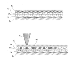
- FIG. 4 shows a cross-sectional view of a film for foil printing in Embodiment 2 of the present invention.
- FIG. 5 is a cross-sectional view showing the production of a read label for an information recording medium from a film for foil printing according to Embodiment 2 of the present invention.
- the second embodiment is a read label for an information recording medium manufactured by thermally transferring information to be recorded on a label in which an adhesive layer, a metal film layer, and a protective film layer are laminated on a base substrate, and an information recording method thereof. is there.
- a foil printing film having a base film provided on a base substrate is attached to a base substrate, and then the foil printing film is partially peeled off. Information is recorded on the base substrate depending on the presence or absence of a label.
- the read label for an information recording medium of the present embodiment is a film for foil printing comprising a label 21 on which an adhesive layer 3, a metal film layer 4 and a protective film layer 5 are laminated and a base film 8. From this, a label for information recording medium is produced by partially peeling off the film for foil printing leaving the label 21.
- the film for foil printing has a configuration in which, for example, a PET film is provided as a base film 8 on a label 21 on which an adhesive layer 3, a metal film layer 4, and a protective film layer 5 are laminated.
- a release layer (not shown) is applied to the surface of the base film 8 that contacts the protective film layer 5. This is because the base film 8 is easily separated from the label 21 to be left as an information recording medium reading label by thermal transfer described later.
- the metal film layer 4 is separately manufactured by vapor deposition, and the adhesive layer 3 is applied to the metal film layer 4.
- the adhesive layer 3 changes the kind of adhesive agent with the material of the base substrate 2 which is a target object to which the reading label for information recording media is thermally transferred.
- a transparent acrylic material can be used as the base substrate 2.
- a film for foil printing comprising four layers of an adhesive layer 3, a metal film layer 4, a translucent protective film layer 5, and a base film 8 is arranged on the base substrate 2. To do.
- the foil printing film is pressed against a predetermined portion of the base substrate 2 by the heated roll member 15 from the base film 8 side of the upper surface of the four-layer foil printing film.
- a fluorine rubber having a hardness of 80 degrees is used as the heated roll member 15, and a film for foil printing is transferred with an appropriate pressure.
- the roll member 15 is pressed against the portion where the label 21 serving as recorded information is left.
- the label 21 composed of three layers of the adhesive layer 3, the metal film layer 4, and the light-transmitting protective film layer 5 is released from the base film 8, and the base substrate 2
- An information recording medium is formed by transferring a film having a three-layer structure, which is a label 21 composed of three layers of an adhesive layer 3, a metal film layer 4, and a translucent protective film layer 5, from the base film 8.
- the reading label 1 for use is formed.
- the reading label 1 for the information recording medium can be easily manufactured using the film for foil printing, so that the base substrate 2 can be manufactured on a product having a complicated shape such as a curved surface or a partial part of the product. It becomes possible.
- the read label 1 for an information recording medium is configured by the presence or absence of the label 21 including the metal layer film 4, as in the first embodiment, the contrast of the read label is improved and the reading reliability is improved. Can do.
- the thickness of each layer is arbitrary.
- the heat of the roll member 15 is set to 180 ° C. to 200 ° C., and the film can be transferred onto the curved surface while the base member 2 is turned by the heated roll member 15.
- a foil printing apparatus for example, a foil printing apparatus manufactured by Navitas can be used, and a film manufactured by Murata Gold Leaf Co., Ltd. can be used as the film for foil printing.
- the detailed dimensions of each layer are, for example, about 16 ⁇ m for the base film 8, 1 to 1.5 ⁇ m for the release layer that becomes the protective film layer 5, and 500 ⁇ m (0.05 ⁇ m) for the aluminum vapor deposition layer that is the metal film layer 4.
- the adhesive layer 3 becomes 2 to 3 ⁇ m.
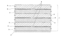
- FIG. 6 shows a multilayered information recording medium reading label according to Embodiment 3 of the present invention, in which the information recording medium reading label 1 of Embodiment 1 is multilayered.
- a translucent protective film layer 5, a metal film layer 4, and a film made of an adhesive layer 3 are transferred and printed on the base substrate 2 a plurality of times, thereby translucent protective film layer. 5, the metal film layer 4, and the adhesive layer 3 are multilayered, and then the information recording unit 6 is formed by irradiating the laser beam 7.
- the film is thermally transferred a plurality of times at the same position, and this thermal transfer can be performed and laminated as many times as the adhesive layer 3 is present.
- the cleaning liquid such as alcohol
- cleaning or immersion of the cleaning liquid is performed. Even if damage such as melting of the protective film layer 5 and the metal film layer 4 due to corrosion due to the cleaning liquid occurs, if the upper information recording medium reading label 1 is removed, the lower information recording medium reading label 1
- the purpose and function of the reading label can be achieved.
- the reading label 1 for the upper information recording medium can achieve the purpose and function as the reading label. It becomes possible to do. In this way, a highly durable reading label can be realized by forming the information recording medium reading label 1 in multiple layers.
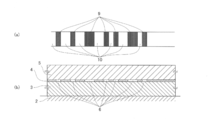
- FIG. 7 is a sectional view showing a method for reading the read label for an information recording medium in Embodiment 4 of the present invention.
- FIG. 8A is a plan view in which a barcode is formed on the reading label for an information recording medium in Embodiment 4 of the present invention
- FIG. 8B is a cross-sectional view.
- FIG. 9 is a perspective view in which a barcode is formed on the information recording medium reading label according to Embodiment 4 of the present invention.
- the content of the information recording medium reading label 1 is recognized by the reading device 12 by moving the information recording medium reading label 1 or the reading device 12.
- the certainty of reading is determined by the contrast and contrast of the information recording unit 6 in the reading label 1 for information recording medium, and the durability of the information recording unit 6 itself causes false detection and malfunction. . Therefore, the durability of the information recording unit 6 itself is very important for realizing reading.
- the metal film layer 4 itself is formed by a thin film such as vapor deposition or sputtering, that is, a metal surface.
- the reflectivity is very high, and a reflected signal with high probability can be obtained. That is, since the signal difference with the reflected signal becomes very large, the contrast becomes clear and the reading probability is very high.
- the information recording unit 6 is formed of a bar code, a transmission side bar code 9 for performing reading, an acrylic resin as a base substrate 2 as a background, and a metal film as a reflection side bar code 10 Since the layer 4 is disposed, a bar code having a high contrast and a clear contrast is formed.
- the information recording medium reading label 1 can be applied to a base substrate 2 having a curved surface, such as a medical biosensor for examining blood or the like.
- the protective film layer 5 may be stained by the blood 16. Information can be read. Accordingly, it is possible to read without misrecognizing the type and manufacturing information of the medical biosensor, and it is possible to measure blood with high reliability.
- information recording is performed by removing the transpiration of the metal film layer. Therefore, the contrast becomes clearer than that in which information recording is performed by changing the color. Resistant to contamination of the protective film layer, the reading reliability of the reading device can be increased.
Landscapes
- Physics & Mathematics (AREA)
- General Physics & Mathematics (AREA)
- Engineering & Computer Science (AREA)
- Theoretical Computer Science (AREA)
- Thermal Transfer Or Thermal Recording In General (AREA)
- Laser Beam Processing (AREA)
- Optical Record Carriers And Manufacture Thereof (AREA)
Abstract
Description
前記接着剤層、および透光性を有する保護膜層の厚さを、前記金属膜層の厚さよりも厚くするとともに、この金属膜層には、この金属膜層の一部が蒸散除去された蒸散除去部を設け、これにより所期の目的を達成するものである。
(実施の形態1)
図1は、本発明の実施の形態1における情報記録媒体用読取ラベルの断面図を示す。図2は、本発明の実施の形態1における情報記録媒体用読取ラベルの製作プロセスでレーザ加工を示す断面図を示す。図3は、本発明の実施の形態1における情報記録媒体用読取ラベルを示す別の断面図を示す。
図4は、本発明の実施の形態2における箔印刷用のフィルムの断面図を示す。図5は、本発明の実施の形態2おける箔印刷用のフィルムから情報記録媒体用読取ラベルの製作を示す断面図を示す。
図6は、本発明の実施の形態3における多層にした情報記録媒体用読取ラベルを示し、実施の形態1の情報記録媒体用読取ラベル1を多層にしたものである。
図7は、本発明の実施の形態4における情報記録媒体用読取ラベルを読取る方法を示す断面図を示す。図8(a)は、本発明の実施の形態4における情報記録媒体用読取ラベルにバーコードを形成した平面図、図8(b)は断面図を示す。図9は、本発明の実施の形態4における情報記録媒体用読取ラベルにバーコードを形成した斜視図を示す。
Claims (11)
- 接着剤層と、この接着剤層の表面側に接して設けた金属膜層と、この金属膜層の表面側に設けた透光性を有する保護膜層を備え、前記接着剤層、および前記透光性を有する保護膜層の厚さを、前記金属膜層の厚さよりも厚くするとともに、
この金属膜層には、この金属膜層の一部が蒸散除去された蒸散除去部を設けたことを特徴とする情報記録媒体用読取ラベル。 - 前記金属膜層の前記蒸散除去部と、その隣接部分で情報記録部を形成したことを特徴とする請求項1に記載の情報記録媒体用読取ラベル。
- 接着剤層、前記透光性を有する保護膜層の厚さは、前記金属膜層の厚さの10倍以上の厚さとしたことを特徴とする請求項1または2に記載の情報記録媒体用読取ラベル。
- 前記金属膜層の前記蒸散除去部に接する接着剤層部分には、蒸散した金属膜層を収容する収容部を形成したことを特徴とする請求項1から3のいずれか一つに記載の情報記録媒体用読取ラベル。
- 前記金属膜層は、アルミニューム、パラジウム、銅、ニッケル、銀、金、鉄の少なくとも一つにより構成されていることを特徴とする請求項1から4のいずれか一つに記載の情報記録媒体用読取ラベル。
- 前記金属膜層は、蒸着またはスパッタ工法により、前記接着剤層の表面側に製膜されていることを特徴とする請求項1から5のいずれか一つに記載の情報記録媒体用読取ラベル。
- 請求項1から6のいずれか一つに記載の情報記録媒体用読取ラベルを、複数層積層した情報記録媒体用読取ラベル。
- 接着剤層と、この接着剤層の表面側に接して設けた金属膜層と、この金属膜層の表面側に設けた透光性を有する保護膜層を備え、
前記接着剤層、および前記透光性を有する保護膜層の厚さを、前記金属膜層の厚さよりも厚くするとともに、この金属膜層に蒸散除去部を設けた情報記録媒体用読取ラベルの情報記録方法であって、
前記透光性を有する保護膜層側から前記金属膜層にレーザ照射することにより、この金属膜層の一部を蒸散除去して蒸散除去部を形成することを特徴とする情報記録媒体用読取ラベルの情報記録方法。 - レーザの波長がYAG波長のレーザと第2高調波長のレーザであることを特徴とする請求項8に記載の情報記録媒体用読取ラベルの情報記録方法。
- 前記接着剤層の、金属膜層の蒸散除去部に接する表面部分には、レーザ照射前に、凹凸面を形成することを特徴とする請求項8または9に記載の情報記録媒体用読取ラベルの情報記録方法。
- 前記接着剤層の前記金属膜層とは反対側の面を、基材に接着し、その後、前記透光性を有する保護膜層側からのレーザ照射を行うことを特徴とする請求項8から10のいずれか一つに記載の情報記録媒体用読取ラベルの情報記録方法。
Priority Applications (4)
| Application Number | Priority Date | Filing Date | Title |
|---|---|---|---|
| EP12773905.0A EP2587470B1 (en) | 2011-04-22 | 2012-04-05 | Read label for information recording medium and information recording method therefor |
| US13/703,757 US8899485B2 (en) | 2011-04-22 | 2012-04-05 | Read label used as information recording medium and method for recording information thereon |
| CN201280001320.8A CN102893314B (zh) | 2011-04-22 | 2012-04-05 | 信息记录介质用读取标签及其信息记录方法 |
| JP2012540213A JPWO2012144146A1 (ja) | 2011-04-22 | 2012-04-05 | 情報記録媒体用読取ラベルとその情報記録方法 |
Applications Claiming Priority (2)
| Application Number | Priority Date | Filing Date | Title |
|---|---|---|---|
| JP2011095774 | 2011-04-22 | ||
| JP2011-095774 | 2011-04-22 |
Publications (1)
| Publication Number | Publication Date |
|---|---|
| WO2012144146A1 true WO2012144146A1 (ja) | 2012-10-26 |
Family
ID=47041281
Family Applications (1)
| Application Number | Title | Priority Date | Filing Date |
|---|---|---|---|
| PCT/JP2012/002377 WO2012144146A1 (ja) | 2011-04-22 | 2012-04-05 | 情報記録媒体用読取ラベルとその情報記録方法 |
Country Status (5)
| Country | Link |
|---|---|
| US (1) | US8899485B2 (ja) |
| EP (1) | EP2587470B1 (ja) |
| JP (2) | JPWO2012144146A1 (ja) |
| CN (1) | CN102893314B (ja) |
| WO (1) | WO2012144146A1 (ja) |
Cited By (1)
| Publication number | Priority date | Publication date | Assignee | Title |
|---|---|---|---|---|
| JP2018089974A (ja) * | 2018-01-10 | 2018-06-14 | 大日本印刷株式会社 | 印字方法 |
Families Citing this family (6)
| Publication number | Priority date | Publication date | Assignee | Title |
|---|---|---|---|---|
| US9531906B2 (en) * | 2010-06-11 | 2016-12-27 | Xerox Corporation | Method for automatic conversion of paper records to digital form |
| CN103971590B (zh) * | 2013-02-01 | 2017-02-22 | 比亚迪股份有限公司 | 一种防伪商标及其制造方法 |
| CN106295755A (zh) * | 2015-05-27 | 2017-01-04 | 东莞文胜鼎电子科技有限公司 | 二维码生成方法、检测方法、检测装置和防伪标签 |
| JP6707332B2 (ja) * | 2015-10-29 | 2020-06-10 | 株式会社トッパンインフォメディア | 情報記録媒体 |
| CN106448439B (zh) * | 2016-10-04 | 2020-12-01 | 勺海数据科技(深圳)有限公司 | 多层防伪标签、其制作方法及使用方法 |
| CN110399937B (zh) * | 2018-04-17 | 2023-05-26 | 鹏鼎控股(深圳)股份有限公司 | 用于印刷电路板的信息检测方法 |
Citations (12)
| Publication number | Priority date | Publication date | Assignee | Title |
|---|---|---|---|---|
| JPH03148390A (ja) | 1989-11-06 | 1991-06-25 | Yamaha Motor Co Ltd | 燃料タンクのブリーザ装置 |
| JPH10333574A (ja) * | 1997-05-30 | 1998-12-18 | Toppan Printing Co Ltd | 偽造防止ラベル材およびその製造方法 |
| JPH11198537A (ja) * | 1998-01-12 | 1999-07-27 | Dainippon Printing Co Ltd | 感熱破壊型パターン形成用複合体 |
| JP2000019963A (ja) * | 1998-06-30 | 2000-01-21 | Lintec Corp | 粘着ラベル積層体の製造方法 |
| JP2001331109A (ja) * | 2000-05-23 | 2001-11-30 | Nikou Insatsu Kk | ゴミ袋貼付用ラベル帳 |
| JP2003150027A (ja) * | 2001-11-08 | 2003-05-21 | Sankyo Seiki Mfg Co Ltd | 金属蒸着型熱転写用ホログラムシートおよびその加工方法 |
| JP2004070272A (ja) * | 2002-06-13 | 2004-03-04 | Sasaki Insatsu:Kk | 積層ラベルとその製造方法 |
| JP2005014492A (ja) * | 2003-06-27 | 2005-01-20 | Dainippon Printing Co Ltd | 印刷媒体 |
| JP2005119106A (ja) * | 2003-10-16 | 2005-05-12 | Toppan Printing Co Ltd | 偽造防止策が施された物品およびその製造方法 |
| JP2007313876A (ja) | 2006-04-28 | 2007-12-06 | Toyo Ink Mfg Co Ltd | レーザ印字方法、及び該方法で得られたレーザ印字を有する包装体、もしくはラベル |
| WO2008032411A1 (en) * | 2006-09-11 | 2008-03-20 | Dai Nippon Printing Co., Ltd. | Device for discriminating authenticity and substrate enabling the discrimination of authenticity |
| JP2009286864A (ja) * | 2008-05-28 | 2009-12-10 | Dic Corp | ラミネート用粘着フィルムおよびレーザーマーキングラベル |
Family Cites Families (17)
| Publication number | Priority date | Publication date | Assignee | Title |
|---|---|---|---|---|
| JPS56105958A (en) * | 1980-01-30 | 1981-08-22 | Sony Corp | Metallic sheet |
| JPS63154280A (ja) * | 1986-12-17 | 1988-06-27 | Fuji Electric Corp Res & Dev Ltd | レ−ザ加工装置 |
| JPH0497272A (ja) * | 1990-08-10 | 1992-03-30 | Toppan Printing Co Ltd | ラベル |
| JPH04234052A (ja) * | 1990-12-28 | 1992-08-21 | Iseto Shiko Kk | 電子写真方式のノンインパクトプリンタによる印字に適合する金属蒸着ラベル |
| DE19642040C1 (de) | 1996-10-11 | 1998-01-15 | Schreiner Etiketten | Mit einem Laserstrahl beschriftbare Folie |
| JPH10142748A (ja) * | 1996-11-06 | 1998-05-29 | Fuji Photo Film Co Ltd | 写真フイルムカートリッジへのラベル貼り付け方法 |
| AUPP231598A0 (en) * | 1998-03-13 | 1998-04-09 | Mikoh Technology Limited | A method of recording information ii |
| EP0985207A1 (en) * | 1997-04-03 | 2000-03-15 | Mikoh Corporation Limited | Information recording method |
| DE20017501U1 (de) * | 2000-10-12 | 2000-12-14 | Schreiner Gmbh & Co Kg | Mit einem Laserstrahl beschriftbare Folie |
| JP4097128B2 (ja) * | 2002-07-01 | 2008-06-11 | 大日本印刷株式会社 | 体積ホログラム積層体作製用ラベル |
| JP4233355B2 (ja) | 2003-01-16 | 2009-03-04 | 株式会社資生堂 | 情報を刻印した積層材料、それを貼付した物品、及び情報コードの観察方法 |
| CN100461208C (zh) | 2003-01-16 | 2009-02-11 | 株式会社资生堂 | 刻印了信息的层叠材料、粘贴该材料的物品及信息码的观察方法 |
| JP2005164788A (ja) * | 2003-12-01 | 2005-06-23 | Tokai Aluminum Foil Co Ltd | 共振ラベル |
| TWI302309B (en) | 2003-12-16 | 2008-10-21 | Victor Company Of Japan | Optical storage medium |
| JP2009034905A (ja) | 2007-08-01 | 2009-02-19 | Nitto Denko Corp | レーザーマーキングラベル |
| JP3148390U (ja) | 2008-11-28 | 2009-02-12 | 株式会社村田金箔 | 印字用レーザマーキング箔 |
| JP5224060B2 (ja) | 2009-04-27 | 2013-07-03 | 大日本印刷株式会社 | 偽造防止媒体 |
-
2012
- 2012-04-05 EP EP12773905.0A patent/EP2587470B1/en active Active
- 2012-04-05 WO PCT/JP2012/002377 patent/WO2012144146A1/ja active Application Filing
- 2012-04-05 CN CN201280001320.8A patent/CN102893314B/zh active Active
- 2012-04-05 JP JP2012540213A patent/JPWO2012144146A1/ja active Pending
- 2012-04-05 US US13/703,757 patent/US8899485B2/en active Active
-
2015
- 2015-06-08 JP JP2015115365A patent/JP2015172780A/ja active Pending
Patent Citations (12)
| Publication number | Priority date | Publication date | Assignee | Title |
|---|---|---|---|---|
| JPH03148390A (ja) | 1989-11-06 | 1991-06-25 | Yamaha Motor Co Ltd | 燃料タンクのブリーザ装置 |
| JPH10333574A (ja) * | 1997-05-30 | 1998-12-18 | Toppan Printing Co Ltd | 偽造防止ラベル材およびその製造方法 |
| JPH11198537A (ja) * | 1998-01-12 | 1999-07-27 | Dainippon Printing Co Ltd | 感熱破壊型パターン形成用複合体 |
| JP2000019963A (ja) * | 1998-06-30 | 2000-01-21 | Lintec Corp | 粘着ラベル積層体の製造方法 |
| JP2001331109A (ja) * | 2000-05-23 | 2001-11-30 | Nikou Insatsu Kk | ゴミ袋貼付用ラベル帳 |
| JP2003150027A (ja) * | 2001-11-08 | 2003-05-21 | Sankyo Seiki Mfg Co Ltd | 金属蒸着型熱転写用ホログラムシートおよびその加工方法 |
| JP2004070272A (ja) * | 2002-06-13 | 2004-03-04 | Sasaki Insatsu:Kk | 積層ラベルとその製造方法 |
| JP2005014492A (ja) * | 2003-06-27 | 2005-01-20 | Dainippon Printing Co Ltd | 印刷媒体 |
| JP2005119106A (ja) * | 2003-10-16 | 2005-05-12 | Toppan Printing Co Ltd | 偽造防止策が施された物品およびその製造方法 |
| JP2007313876A (ja) | 2006-04-28 | 2007-12-06 | Toyo Ink Mfg Co Ltd | レーザ印字方法、及び該方法で得られたレーザ印字を有する包装体、もしくはラベル |
| WO2008032411A1 (en) * | 2006-09-11 | 2008-03-20 | Dai Nippon Printing Co., Ltd. | Device for discriminating authenticity and substrate enabling the discrimination of authenticity |
| JP2009286864A (ja) * | 2008-05-28 | 2009-12-10 | Dic Corp | ラミネート用粘着フィルムおよびレーザーマーキングラベル |
Non-Patent Citations (1)
| Title |
|---|
| See also references of EP2587470A4 |
Cited By (1)
| Publication number | Priority date | Publication date | Assignee | Title |
|---|---|---|---|---|
| JP2018089974A (ja) * | 2018-01-10 | 2018-06-14 | 大日本印刷株式会社 | 印字方法 |
Also Published As
| Publication number | Publication date |
|---|---|
| CN102893314B (zh) | 2015-11-25 |
| EP2587470A1 (en) | 2013-05-01 |
| US20130082111A1 (en) | 2013-04-04 |
| JPWO2012144146A1 (ja) | 2014-07-28 |
| EP2587470B1 (en) | 2016-06-22 |
| CN102893314A (zh) | 2013-01-23 |
| EP2587470A4 (en) | 2014-01-22 |
| US8899485B2 (en) | 2014-12-02 |
| JP2015172780A (ja) | 2015-10-01 |
Similar Documents
| Publication | Publication Date | Title |
|---|---|---|
| JP2015172780A (ja) | 情報記録媒体用読取ラベルとその情報記録方法 | |
| KR19980064659A (ko) | 레이저빔을 사용해서 마킹하는 방법 | |
| US20050255406A1 (en) | Marking on a thin film | |
| JP2009008715A5 (ja) | ||
| EP1100686B1 (en) | Method for marking a laminated film | |
| JP6500380B2 (ja) | 印字方法 | |
| CN108747039B (zh) | 液晶面板标记方法 | |
| JP2011025931A (ja) | 包装材料の印字方法及び印字装置 | |
| US20020153639A1 (en) | Method for marking a laminated film material | |
| JP7330253B2 (ja) | マーク付き光学積層体、及び、マーク付き光学積層体の製造方法 | |
| JP2007042213A (ja) | 光記録媒体の製造方法及びそれを用いて製造された光記録媒体 | |
| JP6121193B2 (ja) | 転写装置、転写方法、及び、転写板 | |
| JP6990760B1 (ja) | マーク付き光学積層体、及び、マーク付き光学積層体の製造方法 | |
| JP2008287847A (ja) | 光記録媒体及びその製造方法 | |
| JP2004247020A (ja) | 光ディスクの製造方法 | |
| AU749161B2 (en) | Method of recording information | |
| JP2011113589A (ja) | 光ディスク | |
| JP2013071330A (ja) | 情報カードおよびその製造方法 | |
| KR20220032522A (ko) | 복합재의 분단 방법 | |
| JPH03250785A (ja) | 多層印刷配線板およびマーキング方法 | |
| JP2007280439A (ja) | 光記録媒体 | |
| JP2007102830A (ja) | 光記録媒体及び光記録媒体の製造方法 | |
| WO2004077424A1 (ja) | 光情報記録担体 | |
| WO1999048076A1 (en) | Method of recording information | |
| JP2006331572A (ja) | 光記録媒体の製造方法及び光記録媒体 |
Legal Events
| Date | Code | Title | Description |
|---|---|---|---|
| WWE | Wipo information: entry into national phase |
Ref document number: 201280001320.8 Country of ref document: CN |
|
| ENP | Entry into the national phase |
Ref document number: 2012540213 Country of ref document: JP Kind code of ref document: A |
|
| WWE | Wipo information: entry into national phase |
Ref document number: 13703757 Country of ref document: US |
|
| 121 | Ep: the epo has been informed by wipo that ep was designated in this application |
Ref document number: 12773905 Country of ref document: EP Kind code of ref document: A1 |
|
| WWE | Wipo information: entry into national phase |
Ref document number: 2012773905 Country of ref document: EP |
|
| NENP | Non-entry into the national phase |
Ref country code: DE |