WO2012144086A1 - 配管固定具、配管固定方法、配管固定具の製造方法 - Google Patents
配管固定具、配管固定方法、配管固定具の製造方法 Download PDFInfo
- Publication number
- WO2012144086A1 WO2012144086A1 PCT/JP2011/063462 JP2011063462W WO2012144086A1 WO 2012144086 A1 WO2012144086 A1 WO 2012144086A1 JP 2011063462 W JP2011063462 W JP 2011063462W WO 2012144086 A1 WO2012144086 A1 WO 2012144086A1
- Authority
- WO
- WIPO (PCT)
- Prior art keywords
- pipe
- locking
- piping
- pipe fixing
- fixing members
- Prior art date
- Legal status (The legal status is an assumption and is not a legal conclusion. Google has not performed a legal analysis and makes no representation as to the accuracy of the status listed.)
- Ceased
Links
Images





Classifications
-
- F—MECHANICAL ENGINEERING; LIGHTING; HEATING; WEAPONS; BLASTING
- F16—ENGINEERING ELEMENTS AND UNITS; GENERAL MEASURES FOR PRODUCING AND MAINTAINING EFFECTIVE FUNCTIONING OF MACHINES OR INSTALLATIONS; THERMAL INSULATION IN GENERAL
- F16L—PIPES; JOINTS OR FITTINGS FOR PIPES; SUPPORTS FOR PIPES, CABLES OR PROTECTIVE TUBING; MEANS FOR THERMAL INSULATION IN GENERAL
- F16L3/00—Supports for pipes, cables or protective tubing, e.g. hangers, holders, clamps, cleats, clips, brackets
- F16L3/08—Supports for pipes, cables or protective tubing, e.g. hangers, holders, clamps, cleats, clips, brackets substantially surrounding the pipe, cable or protective tubing
- F16L3/12—Supports for pipes, cables or protective tubing, e.g. hangers, holders, clamps, cleats, clips, brackets substantially surrounding the pipe, cable or protective tubing comprising a member substantially surrounding the pipe, cable or protective tubing
-
- F—MECHANICAL ENGINEERING; LIGHTING; HEATING; WEAPONS; BLASTING
- F16—ENGINEERING ELEMENTS AND UNITS; GENERAL MEASURES FOR PRODUCING AND MAINTAINING EFFECTIVE FUNCTIONING OF MACHINES OR INSTALLATIONS; THERMAL INSULATION IN GENERAL
- F16L—PIPES; JOINTS OR FITTINGS FOR PIPES; SUPPORTS FOR PIPES, CABLES OR PROTECTIVE TUBING; MEANS FOR THERMAL INSULATION IN GENERAL
- F16L3/00—Supports for pipes, cables or protective tubing, e.g. hangers, holders, clamps, cleats, clips, brackets
- F16L3/08—Supports for pipes, cables or protective tubing, e.g. hangers, holders, clamps, cleats, clips, brackets substantially surrounding the pipe, cable or protective tubing
- F16L3/10—Supports for pipes, cables or protective tubing, e.g. hangers, holders, clamps, cleats, clips, brackets substantially surrounding the pipe, cable or protective tubing divided, i.e. with two members engaging the pipe, cable or protective tubing
- F16L3/1083—Supports for pipes, cables or protective tubing, e.g. hangers, holders, clamps, cleats, clips, brackets substantially surrounding the pipe, cable or protective tubing divided, i.e. with two members engaging the pipe, cable or protective tubing with two members, the two members being hooked in on one side and fastened together on the other side
-
- F—MECHANICAL ENGINEERING; LIGHTING; HEATING; WEAPONS; BLASTING
- F16—ENGINEERING ELEMENTS AND UNITS; GENERAL MEASURES FOR PRODUCING AND MAINTAINING EFFECTIVE FUNCTIONING OF MACHINES OR INSTALLATIONS; THERMAL INSULATION IN GENERAL
- F16L—PIPES; JOINTS OR FITTINGS FOR PIPES; SUPPORTS FOR PIPES, CABLES OR PROTECTIVE TUBING; MEANS FOR THERMAL INSULATION IN GENERAL
- F16L3/00—Supports for pipes, cables or protective tubing, e.g. hangers, holders, clamps, cleats, clips, brackets
- F16L3/08—Supports for pipes, cables or protective tubing, e.g. hangers, holders, clamps, cleats, clips, brackets substantially surrounding the pipe, cable or protective tubing
-
- F—MECHANICAL ENGINEERING; LIGHTING; HEATING; WEAPONS; BLASTING
- F16—ENGINEERING ELEMENTS AND UNITS; GENERAL MEASURES FOR PRODUCING AND MAINTAINING EFFECTIVE FUNCTIONING OF MACHINES OR INSTALLATIONS; THERMAL INSULATION IN GENERAL
- F16L—PIPES; JOINTS OR FITTINGS FOR PIPES; SUPPORTS FOR PIPES, CABLES OR PROTECTIVE TUBING; MEANS FOR THERMAL INSULATION IN GENERAL
- F16L3/00—Supports for pipes, cables or protective tubing, e.g. hangers, holders, clamps, cleats, clips, brackets
- F16L3/08—Supports for pipes, cables or protective tubing, e.g. hangers, holders, clamps, cleats, clips, brackets substantially surrounding the pipe, cable or protective tubing
- F16L3/10—Supports for pipes, cables or protective tubing, e.g. hangers, holders, clamps, cleats, clips, brackets substantially surrounding the pipe, cable or protective tubing divided, i.e. with two members engaging the pipe, cable or protective tubing
- F16L3/1033—Supports for pipes, cables or protective tubing, e.g. hangers, holders, clamps, cleats, clips, brackets substantially surrounding the pipe, cable or protective tubing divided, i.e. with two members engaging the pipe, cable or protective tubing with two members engaging the pipe, cable or tubing, the two members being joined only on one side of the pipe
- F16L3/1041—Supports for pipes, cables or protective tubing, e.g. hangers, holders, clamps, cleats, clips, brackets substantially surrounding the pipe, cable or protective tubing divided, i.e. with two members engaging the pipe, cable or protective tubing with two members engaging the pipe, cable or tubing, the two members being joined only on one side of the pipe and being adapted to accommodate pipes of various diameters
Definitions
- the present invention relates to a pipe fixing tool for holding and fixing a pipe such as a cable, a pipe fixing method, and a manufacturing method of the pipe fixing tool.
- the pipe fixture includes a pipe holding section that holds the pipe, and the pipe fixing section is fixed to a hanger rail or the like provided on the wall surface.
- a pipe fixing tool for fixing the pipe for example, a pipe material fixing tool fixed to the hanger rail, which is in contact with the base portion having the rotation center and the opening side end portion of the hanger rail. And an engaging portion that is provided on one side of the base and engages with a pair of bent pieces of the hanger rail, and a gripping portion that extends to the other side and grips the piping material from both sides.
- the portion includes an elastic piece that can be elastically deformed in the width direction of the hanger rail, and an engagement claw that sandwiches the bent piece of the hanger rail at the contact portion, and the engagement claw is inserted from the opening of the hanger rail. Piping material fixed so that one side of the base is expanded around the center of rotation while being engaged with the bent piece so that it rotates in the longitudinal direction of the hanger rail and presses against the bent piece There is a tool (Patent Document 1).
- the piping material fixing tool for fixing the piping material has a pair of gripping pieces that engage with each other, and includes a gripping portion that grips the piping material with the pair of gripping pieces.
- Locking tooth rows that lock each other are provided on the opposing surfaces of the gripping piece, and the tip of the tool is perpendicular to the engaging direction of the gripping piece between the pair of gripping pieces engaged.
- An insertion groove to be inserted from the direction is provided, and a pair of gripping pieces are separated from each other by pressing the both side surfaces of the insertion groove while inserting and rotating the distal end portion of the tool into the insertion groove.
- There is a piping material fixture formed so as to expand while releasing the locking of the locking tooth row Patent Document 2.
- Patent Documents 1 and 2 are both fixed to a hanger rail, and there are restrictions on the direction of fixing. Moreover, since it is necessary to push a fixing tool into a hanger rail by a deformation
- the present invention has been made in view of such problems, and has a simple structure, can be attached to any support material as long as it has a hole, and is excellent in attachment workability. It is an object to provide a tool and a pipe fixing method using the same.
- the first invention is a pipe fixing tool for fixing a pipe to a support material, and includes a pipe holding part for holding the pipe and a locking part locked to the support material.
- a pair of pipe fixing members are provided to face each other, and an engaging part that engages the pipe holding parts facing each other is formed on the upper part of the pipe holding part, and the engaging parts are opposed to each other.
- a locking claw that protrudes in a direction opposite to the direction is provided, and a taper portion is provided on the opposite surface side of the locking portion so that the distance between the opposing surfaces changes.
- the opposing surface of the member and the other pipe fixing member is connected at the fracture inducing part, and when the engagement parts are moved in the closing direction, the pipe fixing members are separated at the fracture inducing part, In a state where the pipe fixing members are in contact with each other in the vicinity of the tapered portion, the front A piping fixture, characterized in that it is possible to rotate the locking unit in the direction in which the locking claw each other spreads.
- the rupture inducing portion connects a lower edge portion of the tapered portion of one of the pipe fixing members and a position shifted a predetermined distance upward from a lower edge portion of the tapered portion of the other piping fixing member,
- a pair of said pipe fixing members may be connected in the position which shifted
- the pipe fixing member on the side to which the lower edge portion of the taper portion is connected is connected at a position shifted from the lower edge portion of the taper portion by a predetermined distance from the protruding length of the locking claw. It is desirable that the protruding length of the locking claw of the pipe fixing member on the other side is long.
- a pressing portion is provided on the upper portion of the locking claw, and the support material is sandwiched between the pressing portion and the locking claw.
- the breakage inducing portion may be provided in the vicinity of the tapered portion or in the vicinity of the pressing portion of each of the pair of pipe fixing members. In a state where the pair of pipe fixing members are locked to the support member, the cross-sections of the pressing portions may be substantially circular.
- the fracture inducing portion may be formed only in a part in the thickness direction of the pipe fixing member.
- the lower portion of the locking portion may be formed in a substantially weight shape (tapered shape in which the cross-sectional area gradually decreases toward the tip).
- the pair of pipe fixing members are connected to each other at the breakage inducing portion, and the pipe is held and moved in a direction to engage with each other.
- the induction part can be broken. For this reason, it can be made to rotate from a contact part in the direction which the latching claw of each piping fixing member spreads. Therefore, it is excellent in the workability of attaching the pipe fixing tool.
- the connecting portion by the fracture inducing portion is positioned at a position shifted a predetermined distance above the lower edge of the tapered portion of one pipe fixing member and the lower edge of the tapered portion of the other piping fixing member.
- the distance between the locking claws in the connected state can be reduced, and it becomes easy to insert the locking claws into the hole of the support material.
- the engagement of the pipe fixing member on the side connected at a position shifted upward from the lower edge of the taper portion relative to the protruding length of the locking claw of the pipe fixing member on the side to which the lower edge portion of the taper portion is connected By lengthening the protruding length of the pawl, the locking length of the locking pawl after locking can be increased. For this reason, a pipe fixing tool can be reliably fixed to a support material. Further, when the locking claw is inserted into the support member, the longer locking claw is inserted into the hole obliquely. For this reason, there is little influence on the insertion property of the locking claw.
- the fracture inducing portion is formed only in a part in the thickness direction of the pipe fixing member, the force required for the fracture can be reduced, and burrs after the fracture can be reduced.
- the lower portion of the locking portion is formed in a substantially weight shape, it can function as a guide when the locking claw is inserted.
- a second invention is a pipe fixing tool for fixing a pipe to a support material, comprising a pair of pipe fixing members each having a pipe holding part for holding the pipe and a locking part locked to the support material.
- an engaging part that engages the pipe holding parts is formed on the upper part of the pipe holding part.
- a tapered portion is provided so that the distance between the opposing surfaces changes, and the pair of pipe fixing members
- the sizes of the locking portions of the pair of pipe fixing members may be substantially the same, and the lower portions of the locking portions may be formed in a substantially weight shape.
- 3rd invention uses the pipe fixing tool concerning 1st invention, inserts the said latching
- the pipe fixing members are separated from each other by the fracture inducing part by moving the engaging parts in a closing direction, and the pipe fixing members are tapered.
- the locking portion is rotated in a state of being contacted in the vicinity of the portion, the locking claws are widened, and the locking portion is locked to the support material.
- a fourth aspect of the present invention is the pipe fixing tool according to the second aspect of the present invention, wherein a pair of the pipe fixing members are opposed to each other, and the engagement of each of the pipe fixing members is made in the hole formed in the support material.
- the engaging portions are engaged with each other, and the engaging portions are moved in a closing direction, whereby the piping fixing member is
- the locking portion is rotated in a state of being contacted in the vicinity of the taper portion, the locking claws are widened, and locked to the support member by the locking portion.
- the fifth invention is a method of manufacturing a pipe fixture according to the first invention, wherein the pipe fixture is formed by injection molding, and the gate in the injection molding is at least a pair of the pipe fixtures. It is a manufacturing method of a pipe fixture formed in each said locking part of a member, and resin is injected from each said locking part.
- a pipe fixing tool that has a simple structure, can be received by any supporting material as long as it has a hole, and is excellent in mounting workability, and a piping fixing method using the same. Etc. can be provided.
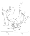
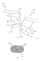
- FIG. 3 is an enlarged view of the locking portions 5a and 5b, (a) an enlarged view of a portion A in FIG. 2, and (b) a sectional view taken along line BB in (a).
- FIG. The figure which shows the state which engaged part 9a, 9b engaged.
- FIG. 8 is a diagram showing a state in which the direction of the pipe fixing tool with respect to the support member 23 is changed, and is a cross-sectional view taken along the line GG of FIG.
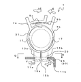
- FIG. 1 is a perspective view showing the pipe fixture 1
- FIG. 2 is a front view showing the pipe fixture 1.
- the pipe fixture 1 is, for example, a resin member.
- the pipe fixing tool 1 is configured by connecting a pair of pipe fixing members 7a and 7b.
- the pipe fixing members 7a and 7b are connected to each other by the fracture inducing portion 19 so as to face each other. Since the pipe fixing members 7a and 7b are mostly formed symmetrically, the configuration of the pipe fixing member 7a will be mainly described below, and redundant description will be omitted.
- the pipe fixing member 7a includes a pipe holding part 3a and a locking part 5a formed at the lower part of the pipe holding part 3a.
- the pipe holding part 3a is a part that holds the pipe.
- the pipe holding part 3a is formed in a halved shape corresponding to the pipe shape to be held. That is, the shape which can hold
- a protrusion 17 is formed along the circumferential direction as needed on at least a part of the inner surface of the pipe holding portion 3a.
- the protrusion 17 prevents the pipe from being displaced in the axial direction by fitting the protrusion 17 into the concave portion on the outer surface of the corrugated pipe when the pipe to be held is a corrugated pipe.
- the shape and the like of the protrusions 17 are appropriately designed according to the shape of the piping to be held.
- the engaging part 9a is formed in the upper part of the pipe holding part 3a.
- a plurality of tooth rows are formed in the engaging portion 9a.
- the locking part 5a has a locking claw 11a and a pressing part 13a.
- the locking claw 11a is a protrusion that protrudes in the direction (outward) opposite to the opposing surfaces of the pair of pipe fixing members 7a and 7b.
- the locking claw 11a serves as a part for locking the pipe fixture 1 to a support material to be described later.
- a pressing portion 13a that expands in diameter with a groove shape is formed on the upper portion (on the pipe holding portion 3a side) of the locking claw 11a.
- the pressing portion 13a serves as a portion that comes into contact with an installation surface of a support material to be described later. That is, the support member described later is locked so as to be sandwiched between the locking claw 11a and the pressing portion 13a.
- a tapered portion 15a is formed on a part of the inner surface side of the locking portion 5a (the surface facing the locking portion 5b of the opposing pipe fixing member 7b).
- the tapered portions 15a and 15b of the locking portions 5a and 5b are engaged by the tapered portions 15a and 15b when a part of the locking portions 5a and 5b is brought into contact with the pipe fixing members 7a and 7b facing each other. It forms so that the distance between stop part 5a, 5b may spread. That is, the locking portions 5a and 5b are not entirely in surface contact with each other, and the locking portions 5a and 5b are moved upward or downward (in the direction of the pipe holding portions 3a and 3b or the opposite side). Is formed in the direction of separating.
- the tapered portions 15a and 15b that are linear in a front view are formed below the locking portions 5a and 5b
- the present invention is not limited to this.
- the tapered portions 15a and 15b may be formed in a curved shape when viewed from the front. Further, when the tapered portions 15a and 15b are formed in a curved shape, they may be formed on the entire inner surface of the locking portions 5a and 5b. A plurality of tapered shapes may be combined.
- FIG. 3A is an enlarged view of part A in FIG.
- the pipe fixing members 7 a and 7 b are connected by the fracture inducing portion 19.
- the fracture inducing portion 19 is formed in the vicinity of the tapered portions 15a and 15b of the respective locking portions 5a and 5b.
- breakage inducing portion 19 is on the inner surface side of one locking portion 5b and between a position shifted a predetermined distance above the lower edge portion and the vicinity of the lower edge portion of the other locking portion 5a. It is desirable to be formed. That is, it is desirable that the approximate center of the locking portion 5b in the height direction and the vicinity of the lower end of the locking portion 5a are connected.
- tip of the latching claw 11b may be as perpendicular
- the outward protruding length of the locking claw 11b located on the lower side in the connected state (the locking claw of the pipe fixing member on the side connected at a position shifted upward from the lower edge of the tapered portion) Is formed longer than the protruding length of the locking claw 11a (the locking claw of the pipe fixing member on the side where the lower edge of the tapered portion is connected).
- FIG. 3B is a cross-sectional view taken along the line BB of FIG.
- the fracture inducing portion 19 is formed only in a part of the width direction (vertical direction in the drawing) between the locking portions 5a and 5b. It is desirable that the fracture inducing portion 19 is as small as possible. That is, as will be described later, when the breakage inducing portion 19 is broken, it is desirable to make the convex portions remaining between the locking portions 5a and 5b as small as possible.
- FIG. 4 is a perspective view showing the support member 23 on which the pipe fixture 1 is installed.
- the support member 23 is, for example, a substantially U-shaped metal fitting, and the opening side is inserted into a part of a fixing portion such as an angle or an H steel beam, and is fixed with a bolt or the like not shown from one surface.
- Holes 25 are formed on the other surface of the support member 23.
- protruding edges 29 projecting outward are formed for the purpose of reinforcement or the like.
- a range surrounded by the protruding portion 29 is a flat portion 27, which is a portion where the pipe fixture is locked. That is, the projecting edge portions 29 are formed on both sides of the flat portion 27 so as to rise outward, and the holes 25 are formed substantially in the middle of the projecting edge portions 29 at both ends.
- the piping fixing tool 1 of this invention can be attached other than the support material 23 as shown in figure.
- other shapes may be used as long as the engaging portion of the pipe fixing tool 1 has a hole into which it can be inserted.
- the hole 25 does not necessarily need to be circular.
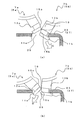
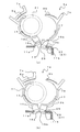
- FIG. 5 is a diagram showing a process of attaching the pipe fixture 1 to the support member 23.
- one of the locking claws 11b is inserted into the hole 25 in a state where the pipe fixing members 7a and 7b are connected (in the direction of arrow C in the figure). That is, the locking claw 11 b is inserted into the hole 25 so that the front end of the locking claw 11 b is located inside the support member 23 and the pressing portion 13 b is located on the outer surface side of the support material 23.
- the other locking claw 11a is inserted into the hole 25 (in the direction of arrow D in the figure).
- the leading end direction of the locking claw 11a is connected so as to face slightly downward with respect to the leading end direction of the locking claw 11b. Therefore, if the entire pipe fixing tool is rotated so that the tip of the locking claw 11b is caught on the edge (inner surface) of the hole 25 (clockwise in the figure), the locking claw 11b is substantially the same as the surface of the flat portion 27. It rotates in the direction which becomes parallel, and it is inserted in the hole 25 in the state which the front-end
- the locking claw 11a is inserted into the hole 25 in a state where the locking claw 11a is inclined, the tip of the locking claw 11a is not caught on the upper surface of the support member 23. That is, in the state where the locking portions 5a and 5b are connected, the entire width between the locking claws of the entire locking portion inserted into the hole 25 can be reduced. For this reason, it is excellent in the insertion property of a latching claw.
- a pipe 31 to be fixed is installed between the pipe holding portions 3a and 3b of the pipe fixing members 7a and 7b.
- the engaging portions 9a and 9b of the respective pipe fixing members 7a and 7b are moved in a direction approaching each other (in the direction of arrow E in the figure).
- the pipe holding portions 3a and 3b rotate with each other with the position of the connecting portion (breakage inducing portion 19) as a starting point.
- the locking claws 11a and 11b rotate in the direction away from each other (the direction of opening outward) from the position of the connecting portion (breaking induction portion 19) as a starting point (in the direction of arrow F in the figure).
- FIG. 7 is a diagram showing a state in which the engaging portions 9a and 9b are engaged.
- the pipe 31 is sandwiched and fixed between the pipe holding portions of the pipe fixing members 7a and 7b.
- the locking claws 11 a and 11 b rotate outward, and the locking claws 11 a and 11 b are locked to the edge of the hole 25 of the support member 23. That is, the flat portion 27 of the support member 23 is sandwiched between the upper surfaces of the locking claws 11 a and 11 b and the lower surfaces of the pressing portions 13 a and 13 b, and the pipe fixture 1 is locked to the support material 23.
- FIG. 8A is a cross-sectional view taken along the line GG in FIG.
- the holding parts 13a and 13b are arranged on the flat part 27 in a state of facing each other.
- the shape is substantially circular. That is, the cross-sectional shape in which the pressing portions 13a and 13b are combined with each other is not rectangular, and a rectangular corner is not formed.
- FIG. 8B is a diagram showing a state (H direction in FIG. 8A) in which the fixing direction of the pipe fixing tool is rotated by 90 ° with respect to the support member 23 from the state of FIG. 8A. .
- the pipe fixing tool can be rotated with respect to the support member 23 even when the locking claws 11 a and 11 b of the pipe fixing tool are inserted into the holes 25. That is, the pressing portions 13a and 13b that are in contact with the upper surface side of the support member 23 are not formed with rectangular corners in the cross section. There is no interference with the protrusion 29 of the material 23.
- the substantially circular shape in which the cross-sectional shapes of the holding portions 13a and 13b are combined is not necessarily a complete circular shape, and as described above, the shape in which the corners are chamfered so as to chamfer the corners in the rectangular cross section. I just need it. That is, when the pipe fixture 1 is rotated with respect to the support member 23, the distance from the center of rotation to the outer edges of the pressing portions 13a and 13b in the cross section may be formed approximately gently over the entire circumference.
- the pipe fixing members 7a and 7b are connected, and by bringing the engaging parts 9a and 9b closer to hold the pipe, the breakage inducing part 19 is broken, and the pipe fixing member 7a. 7b can be separated.
- the separated pipe fixing members 7a and 7b open the locking parts 11a and 11b outwardly in accordance with the engagement of the engaging parts 9a and 9b, and simultaneously hold the pipes, and at the same time support members 23 of the pipe fixing tool 1. Can be locked.
- the fracture inducing portion 19 is not formed at the same position of the pipe fixing members 7a and 7b, but is formed at positions shifted from each other. For this reason, in the connected state, the respective directions of the locking claws 11a and 11b are not aligned on a straight line but form a predetermined angle. Therefore, when the locking claws 11a and 11b are inserted into the holes 25, the locking claws 11a and 11b can be easily inserted into the holes 25 by sequentially inserting the locking claws 11a and 11b one by one.
- the breakage inducing portion 19 is formed only in a part in the width direction between the locking portions 5a and 5b. For this reason, the connection cross-sectional area of the breakage induction part 19 is small, and the breakage induction part 19 can be easily broken. In addition, the small protrusions remaining on the inner surface of the locking portion after breaking can be reduced.
- the pipe holding portions 3a and 3b do not come into contact with the upper surface of the support member 23 by the pressing portions 13a and 13b.
- the pipe fixing tool 1 can also be rotated on the support material 23 because the cross-section in a state where the pressing portions 13a and 13b are combined has a substantially circular shape. For this reason, the pipe fixture 1 can be attached to the support member 23 at an arbitrary angle. Therefore, the degree of freedom of piping installation is high.
- the protruding length to the outside of the locking claw 11b (the locking claw of the pipe fixing member on the side connected at a position shifted upward from the lower edge portion of the taper portion) located on the lower side in the connected state Is formed longer than the protruding length of the locking claw 11a (the locking claw of the pipe fixing member on the side where the lower edge of the taper portion is connected), thereby locking the locking claw 11b after locking.
- the length can be increased. For this reason, the pipe fixture 1 can be reliably fixed to the support member 23. Further, when the locking claw 11 b is inserted into the hole 25, the longer locking claw 11 b is inserted into the hole 25 obliquely. For this reason, there is little influence on the insertion property of the locking claw 11b.
- FIG. 9 is a schematic view showing a state in which the pipe fixture 1 is formed by injection molding.
- the illustration of the mold and the like is omitted.
- the pipe fixture 1 is formed by injection molding, for example.
- the gates 12a and 12b filled with the resin are formed in both the locking portions 5a and 5b. Particularly desirably, it is the lower portion of the locking portion (locking claw) as shown in the figure.
- the resin injected from the gate 12a to the locking part 5a (locking claw 11a) flows from the end toward the pipe fixing part (in the direction of arrow J in the figure).
- the resin injected from the gate 12b to the locking portion 5b (locking claw 11b) flows from the end toward the pipe fixing portion (in the direction of arrow K in the figure).
- the fracture inducing portion 19 becomes a boundary between the resins injected from the respective gates 12a and 12b. In such a joint part of the resin, the strength of the molded product is low and cracking is likely to occur compared to other parts. For this reason, as mentioned above, when fixing the pipe fixture 1, the fracture inducing portion 19 can be more easily broken. Therefore, the pipe fixture 1 having excellent workability can be obtained.
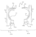
- FIG. 10 is a diagram illustrating a pipe fixture 1a according to the second embodiment.
- the pipe fixture 1a has substantially the same configuration as the pipe fixture 1, but differs in that it does not have the fracture inducing portion 1. That is, the pipe fixing tools 1a and 1b are separated into the pipe fixing members 7a and 7b in advance. Note that the same configuration is used when the pipe fixture 1 is reused after use (after the pipe fixing members 7a and 7b are separated).
- the piping fixture 1a is used as follows. First, as shown in FIG. 10A, the locking claw 11 b of one pipe fixing member 7 b is inserted into the hole 25 of the support member 23. Further, the locking claw 11a of the pipe fixing member 7a is inserted into the hole 25 (in the direction of arrow I in the figure) and arranged so as to face the pipe fixing member 7b. At this time, the pipe 31 is disposed between the pipe fixing members 7a and 7b.
- the pipe fixture 1a substantially the same effect as the pipe fixture 1 can be obtained. Moreover, since the pipe fixing members 7a and 7b are separated, they can be inserted into the holes 25 separately. For this reason, the freedom degree of work is high.
- a pipe fixture 40 shown in FIG. 11 may be used.
- the pipe fixture 40 has substantially the same configuration as the pipe fixture 1a (1), but the configuration of the locking claws is different. That is, the lower portions of the locking claws 41a and 41b of the pipe fixture 40 are formed in a substantially weight shape.
- the locking claws 41a and 41b are formed with substantially the same size.
- the lower surfaces of the locking claws 41a and 41b are substantially weight-shaped, they function as guides when the locking claws are inserted into the holes. For this reason, it is excellent in the insertion property to the hole 25 of the latching claws 41a and 41b.
- the cross-sectional shape when the pressing portions 13a and 13b are combined is a substantially circular shape, but the present invention is not limited to this.
- it is good also as a substantially rectangular shape which has a linear part so that it may contact a protrusion part, when a piping fixing tool is attached to a support material.
- the pipe fixing tool cannot be rotated while attached to the support member, but the pipe fixing tool can be restricted from rotating during use. Also in this case, it is possible to attach the pipe fixing tool in different directions in the 90 ° direction.
- the lower portion of the locking portion of the pipe fixture having the breakage inducing portion may be formed in a weight shape, and in this case, the length of one locking claw may be increased.
Landscapes
- Engineering & Computer Science (AREA)
- General Engineering & Computer Science (AREA)
- Mechanical Engineering (AREA)
- Supports For Pipes And Cables (AREA)
Abstract
Description
3a、3b………配管保持部
5a、5b………係止部
7a、7a………配管固定部材
9a、9b………係合部
11a、11b、41a、41b………係止爪
12a、12b………ゲート
13a、13b………押さえ部
15a、15b………テーパ部
17………突起
19………破断誘起部
23………支持材
25………孔
27………平坦部
29………突縁部
31………配管
Claims (13)
- 支持材に配管を固定する配管固定具であって、
配管を保持する配管保持部と、支持材に係止される係止部とを具備する一対の配管固定部材が互いに対向して設けられ、
前記配管保持部の上部には、対向する前記配管保持部同士を係合する係合部が形成され、
前記係止部には、互いの対向方向とは逆方向に突出する係止爪が設けられるとともに、前記係止部の対向面側には、互いの対向面間の距離が変化するようにテーパ部が設けられ、
一方の前記配管固定部材と、他方の前記配管固定部材との対向面が破断誘起部で連結されており、
前記係合部同士を閉じる方向に移動させると、前記破断誘起部で前記配管固定部材同士が分離し、前記配管固定部材同士が前記テーパ部近傍で接触した状態で、前記係止爪同士が広がる方向に前記係止部を回動させることが可能であることを特徴とする配管固定具。 - 前記破断誘起部は、一方の前記配管固定部材の前記テーパ部の下縁部と、他方の前記配管固定部材の前記テーパ部の下縁部から所定の距離上方にずれた位置とを連結し、一対の前記配管固定部材同士が上下方向にずれた位置で連結されることを特徴とする請求項1記載の配管固定具。
- 前記テーパ部の下縁部が連結された側の前記配管固定部材の前記係止爪の突出長さよりも、前記テーパ部の下縁部から所定の距離上方にずれた位置で連結された側の前記配管固定部材の前記係止爪の突出長さが長いことを特徴とする請求項2記載の配管固定具。
- 前記係止爪の上部には押さえ部が設けられ、前記押さえ部と前記係止爪とで前記支持材を挟み込むことが可能であることを特徴とする請求項1記載の配管固定具。
- 前記破断誘起部は、一対の前記配管固定部材のそれぞれの前記テーパ部近傍または前記押さえ部近傍に設けられることを特徴とする請求項4記載の配管固定具。
- 一対の前記配管固定部材を前記支持材に係止した状態において、それぞれの前記押さえ部の断面を合わせると略円形状となることを特徴とする請求項4記載の配管固定具。
- 前記破断誘起部は、前記配管固定部材の厚み方向の一部にのみ形成されることを特徴とする請求項1記載の配管固定具。
- 前記係止部の下部が略錘状に形成されることを特徴とする請求項1記載の配管固定具。
- 支持材に配管を固定する配管固定具であって、
配管を保持する配管保持部と、支持材に係止される係止部とを具備する一対の配管固定部材からなり、
一対の配管固定部材を対向させた状態で、
前記配管保持部の上部には、前記配管保持部同士を係合する係合部が形成され、
前記係止部には、互いの対向方向とは逆方向に突出する係止爪が設けられるとともに、前記係止部の対向面側には、互いの対向面間の距離が変化するようにテーパ部が設けられ、
一対の前記配管固定部材の前記係止部同士を係合し、前記係合部同士を閉じる方向に移動させると、前記配管固定部材同士が前記テーパ部近傍で接触した状態で、前記係止爪同士が広がる方向に前記係止部を回動させることが可能であることを特徴とする配管固定具。 - 一対の前記配管固定部材のそれぞれの前記係止部の大きさが略同一であり、前記係止部の下部が略錘状に形成されることを特徴とする請求項9記載の配管固定具。
- 請求項1記載の配管固定具を用い、
前記支持材に形成された孔に、前記破断誘起部で連結されたそれぞれの前記配管固定部材の前記係止部を挿入し、
前記配管保持部に配管を配置した状態で、前記係合部同士を閉じる方向に移動させることで、前記破断誘起部で前記配管固定部材同士を分離するとともに、前記配管固定部材同士を前記テーパ部近傍で接触させた状態で前記係止部を回動させて、前記係止爪同士を広げ、
前記係止部で前記支持材に係止することを特徴とする配管固定方法。 - 請求項9記載の配管固定具を用い、
一対の前記配管固定部材を対向させて、前記支持材に形成された孔に、それぞれの前記配管固定部材の前記係止部を挿入し、
前記配管保持部に配管を配置した状態で、互いの前記係合部同士を係合し、
前記係合部同士を閉じる方向に移動させることで、前記配管固定部材を前記テーパ部近傍で接触させた状態で前記係止部を回動させて、前記係止爪同士を広げ、
前記係止部で前記支持材に係止することを特徴とする配管固定方法。 - 請求項1記載の配管固定具の製造方法であって、
前記配管固定具は、射出成型により形成され、
射出成型におけるゲートが、少なくとも、一対の前記配管固定部材のそれぞれの前記係止部に形成され、それぞれの前記係止部から樹脂が射出されることを特徴とする配管固定具の製造方法。
Priority Applications (2)
| Application Number | Priority Date | Filing Date | Title |
|---|---|---|---|
| KR1020127028799A KR20130138084A (ko) | 2011-04-20 | 2011-06-13 | 배관고정구, 배관고정방법, 배관고정구의 제조방법 |
| CN2011800223451A CN102869912A (zh) | 2011-04-20 | 2011-06-13 | 管道夹具、管道固定方法、管道夹具的制造方法 |
Applications Claiming Priority (2)
| Application Number | Priority Date | Filing Date | Title |
|---|---|---|---|
| JP2011093617A JP4885321B1 (ja) | 2011-04-20 | 2011-04-20 | 配管固定具、配管固定方法、配管固定具の製造方法 |
| JP2011-093617 | 2011-04-20 |
Publications (1)
| Publication Number | Publication Date |
|---|---|
| WO2012144086A1 true WO2012144086A1 (ja) | 2012-10-26 |
Family
ID=45851276
Family Applications (1)
| Application Number | Title | Priority Date | Filing Date |
|---|---|---|---|
| PCT/JP2011/063462 Ceased WO2012144086A1 (ja) | 2011-04-20 | 2011-06-13 | 配管固定具、配管固定方法、配管固定具の製造方法 |
Country Status (4)
| Country | Link |
|---|---|
| JP (1) | JP4885321B1 (ja) |
| KR (1) | KR20130138084A (ja) |
| CN (1) | CN102869912A (ja) |
| WO (1) | WO2012144086A1 (ja) |
Cited By (5)
| Publication number | Priority date | Publication date | Assignee | Title |
|---|---|---|---|---|
| JP2017109671A (ja) * | 2015-12-18 | 2017-06-22 | 住友電装株式会社 | クリップ装置 |
| JP2020003000A (ja) * | 2018-06-28 | 2020-01-09 | 有限会社アールストーン | サドルバンド |
| JP2020002999A (ja) * | 2018-06-28 | 2020-01-09 | 有限会社アールストーン | サドルバンド |
| JP2020003001A (ja) * | 2018-06-28 | 2020-01-09 | 有限会社アールストーン | サドルバンド |
| JP2020012537A (ja) * | 2018-07-20 | 2020-01-23 | 有限会社アールストーン | サドルバンド |
Families Citing this family (13)
| Publication number | Priority date | Publication date | Assignee | Title |
|---|---|---|---|---|
| CN102856845B (zh) * | 2012-05-31 | 2015-10-14 | 浙江吉利汽车研究院有限公司杭州分公司 | 铰链线束卡扣结构 |
| JP5821044B2 (ja) * | 2013-03-26 | 2015-11-24 | 丸井産業株式会社 | 長尺材固定金具 |
| CN104180124A (zh) * | 2014-09-02 | 2014-12-03 | 贾海亮 | 一种漏水管定位器 |
| CN104565551A (zh) * | 2014-12-05 | 2015-04-29 | 四川邮科通信技术有限公司 | 一种通信用电缆夹持装置 |
| CN104868424B (zh) * | 2015-04-20 | 2018-02-27 | 国网辽宁省电力有限公司鞍山供电公司 | 用于10kV电力架空线路的立式绝缘子棘扣及使用方法 |
| CN106838470A (zh) * | 2015-12-06 | 2017-06-13 | 天津蓝盟自动控制设备科技有限公司 | 一种消防管道安装固定器具 |
| CN109000041A (zh) * | 2017-06-06 | 2018-12-14 | 福特环球技术公司 | 管道固定装置 |
| CN107228230A (zh) * | 2017-06-19 | 2017-10-03 | 芜湖侨云友星电气工业有限公司 | 一种车身线束固定件 |
| CN111847097A (zh) * | 2019-04-23 | 2020-10-30 | 刘战军 | 多功能线缆拖行器 |
| WO2020240624A1 (ja) * | 2019-05-24 | 2020-12-03 | 日栄インテック株式会社 | 配管支持具 |
| CN111605496B (zh) * | 2020-06-04 | 2022-03-29 | 安徽江淮汽车集团股份有限公司 | 管线固定结构 |
| CN112467649B (zh) * | 2020-12-04 | 2022-07-19 | 国网河南省电力公司洛阳供电公司 | 一种电线固定构件及其使用方法 |
| CN116505450B (zh) * | 2023-06-30 | 2023-10-13 | 国网浙江省电力有限公司岱山县供电公司 | 一种线缆定位夹 |
Citations (5)
| Publication number | Priority date | Publication date | Assignee | Title |
|---|---|---|---|---|
| JPS52137269U (ja) * | 1976-04-15 | 1977-10-18 | ||
| JPS60146388U (ja) * | 1984-03-09 | 1985-09-28 | 三菱電機株式会社 | 配線用クランパ |
| JPH0471887U (ja) * | 1990-10-30 | 1992-06-25 | ||
| JP2001330175A (ja) * | 2000-05-22 | 2001-11-30 | Yazaki Corp | ワイヤーハーネス固定用クリップ |
| JP2008298153A (ja) * | 2007-05-30 | 2008-12-11 | Mirai Ind Co Ltd | 配線・配管材固定具 |
-
2011
- 2011-04-20 JP JP2011093617A patent/JP4885321B1/ja active Active
- 2011-06-13 CN CN2011800223451A patent/CN102869912A/zh active Pending
- 2011-06-13 WO PCT/JP2011/063462 patent/WO2012144086A1/ja not_active Ceased
- 2011-06-13 KR KR1020127028799A patent/KR20130138084A/ko not_active Withdrawn
Patent Citations (5)
| Publication number | Priority date | Publication date | Assignee | Title |
|---|---|---|---|---|
| JPS52137269U (ja) * | 1976-04-15 | 1977-10-18 | ||
| JPS60146388U (ja) * | 1984-03-09 | 1985-09-28 | 三菱電機株式会社 | 配線用クランパ |
| JPH0471887U (ja) * | 1990-10-30 | 1992-06-25 | ||
| JP2001330175A (ja) * | 2000-05-22 | 2001-11-30 | Yazaki Corp | ワイヤーハーネス固定用クリップ |
| JP2008298153A (ja) * | 2007-05-30 | 2008-12-11 | Mirai Ind Co Ltd | 配線・配管材固定具 |
Cited By (5)
| Publication number | Priority date | Publication date | Assignee | Title |
|---|---|---|---|---|
| JP2017109671A (ja) * | 2015-12-18 | 2017-06-22 | 住友電装株式会社 | クリップ装置 |
| JP2020003000A (ja) * | 2018-06-28 | 2020-01-09 | 有限会社アールストーン | サドルバンド |
| JP2020002999A (ja) * | 2018-06-28 | 2020-01-09 | 有限会社アールストーン | サドルバンド |
| JP2020003001A (ja) * | 2018-06-28 | 2020-01-09 | 有限会社アールストーン | サドルバンド |
| JP2020012537A (ja) * | 2018-07-20 | 2020-01-23 | 有限会社アールストーン | サドルバンド |
Also Published As
| Publication number | Publication date |
|---|---|
| CN102869912A (zh) | 2013-01-09 |
| KR20130138084A (ko) | 2013-12-18 |
| JP4885321B1 (ja) | 2012-02-29 |
| JP2012225424A (ja) | 2012-11-15 |
Similar Documents
| Publication | Publication Date | Title |
|---|---|---|
| JP4885321B1 (ja) | 配管固定具、配管固定方法、配管固定具の製造方法 | |
| JP5243914B2 (ja) | ホールプラグ | |
| EP2549050B1 (en) | Corner key and frame assembly | |
| US20140042704A1 (en) | Seal aligning and retaining assembly and method of retaining a seal | |
| JP4945019B2 (ja) | 配線・配管材固定具 | |
| WO2010096441A1 (en) | Raceway for instrumentation lines | |
| US20160053791A1 (en) | Attachment element | |
| BR102014020500A2 (pt) | sistema de alinhamento por cálculo de média elástica | |
| CN107208826A (zh) | 管夹 | |
| JP6435231B2 (ja) | 留め具 | |
| KR20190002186A (ko) | 철근 커플러 | |
| JP5798593B2 (ja) | 天井下地材及び天井構造 | |
| JP5839879B2 (ja) | 配管固定具、配管固定方法 | |
| JP5025439B2 (ja) | デッキプレート用吊り金具およびそれを使用した吊り構造 | |
| JP4750753B2 (ja) | 配線・配管材固定具 | |
| KR101417507B1 (ko) | 강관 접합 구조물 | |
| CN107906256B (zh) | 一种管夹 | |
| JP5584348B1 (ja) | 建築用ルーバーパネルの落下防止構造 | |
| US7478509B2 (en) | Device and method for connecting profiles | |
| JP2007321488A (ja) | セグメントの継手構造 | |
| KR101494647B1 (ko) | 합성수지관 연결장치 | |
| JP6383684B2 (ja) | 建造物 | |
| JP5760211B1 (ja) | C形鋼用取付具 | |
| JP4109688B2 (ja) | C型部材に係合可能な係合部材、及び係合部材セット | |
| JP2013104537A (ja) | 取付具 |
Legal Events
| Date | Code | Title | Description |
|---|---|---|---|
| WWE | Wipo information: entry into national phase |
Ref document number: 201180022345.1 Country of ref document: CN |
|
| ENP | Entry into the national phase |
Ref document number: 20127028799 Country of ref document: KR Kind code of ref document: A |
|
| 121 | Ep: the epo has been informed by wipo that ep was designated in this application |
Ref document number: 11863945 Country of ref document: EP Kind code of ref document: A1 |
|
| NENP | Non-entry into the national phase |
Ref country code: DE |
|
| 122 | Ep: pct application non-entry in european phase |
Ref document number: 11863945 Country of ref document: EP Kind code of ref document: A1 |