WO2012141061A2 - 光学異方性パラメータ測定装置、測定方法及び測定用プログラム - Google Patents
光学異方性パラメータ測定装置、測定方法及び測定用プログラム Download PDFInfo
- Publication number
- WO2012141061A2 WO2012141061A2 PCT/JP2012/059314 JP2012059314W WO2012141061A2 WO 2012141061 A2 WO2012141061 A2 WO 2012141061A2 JP 2012059314 W JP2012059314 W JP 2012059314W WO 2012141061 A2 WO2012141061 A2 WO 2012141061A2
- Authority
- WO
- WIPO (PCT)
- Prior art keywords
- reflected light
- wave plate
- sample
- light intensity
- optical
- Prior art date
- Legal status (The legal status is an assumption and is not a legal conclusion. Google has not performed a legal analysis and makes no representation as to the accuracy of the status listed.)
- Ceased
Links
Images

Classifications
-
- G—PHYSICS
- G01—MEASURING; TESTING
- G01N—INVESTIGATING OR ANALYSING MATERIALS BY DETERMINING THEIR CHEMICAL OR PHYSICAL PROPERTIES
- G01N21/00—Investigating or analysing materials by the use of optical means, i.e. using sub-millimetre waves, infrared, visible or ultraviolet light
- G01N21/17—Systems in which incident light is modified in accordance with the properties of the material investigated
- G01N21/21—Polarisation-affecting properties
-
- G—PHYSICS
- G01—MEASURING; TESTING
- G01N—INVESTIGATING OR ANALYSING MATERIALS BY DETERMINING THEIR CHEMICAL OR PHYSICAL PROPERTIES
- G01N21/00—Investigating or analysing materials by the use of optical means, i.e. using sub-millimetre waves, infrared, visible or ultraviolet light
- G01N21/84—Systems specially adapted for particular applications
- G01N21/88—Investigating the presence of flaws or contamination
- G01N21/95—Investigating the presence of flaws or contamination characterised by the material or shape of the object to be examined
- G01N2021/9513—Liquid crystal panels
Definitions
- the present invention relates to an optical anisotropy parameter measuring apparatus, a measuring method, and a measuring program for measuring the orientation of an optical axis and the magnitude of anisotropy of a sample having optical anisotropy, and in particular, inspection of a liquid crystal alignment film, etc. It is suitable for use.
- the liquid crystal display has a back glass substrate with a transparent electrode and alignment film laminated on the surface, and a front glass substrate with a color filter, transparent electrode and alignment film laminated on the surface, with the alignment films facing each other through a spacer,
- the liquid crystal is sealed in the gap between the alignment films, and a polarizing filter is laminated on both the front and back sides.
- the liquid crystal molecules in order for the liquid crystal display to operate normally, the liquid crystal molecules must be uniformly arranged in the same direction, and the alignment film determines the directionality of the liquid crystal molecules.
- This alignment film can align the liquid crystal molecules because it has molecular alignment. If the alignment film has a uniform molecular alignment over its entire surface, it is difficult to cause defects in the liquid crystal display. If there is an uneven part of the molecular orientation, the direction of the liquid crystal molecules will be disturbed, resulting in a defective liquid crystal display. That is, the quality of the alignment film directly affects the quality of the liquid crystal display, and if there is a defect in the alignment film, the directionality of the liquid crystal molecules is disturbed, resulting in a defect in the liquid crystal display.
- This method irradiates a sample such as a liquid crystal alignment film obliquely with incident light and detects the polarization state of the reflected light, and is based on the reflected light intensity obtained by rotating the optical system or the sample stage.
- a sample such as a liquid crystal alignment film obliquely with incident light and detects the polarization state of the reflected light, and is based on the reflected light intensity obtained by rotating the optical system or the sample stage.
- the reflected light is reflected at the same reflection angle as the incident angle, so the optical paths of the incident light and the reflected light are secured on both sides with respect to the measurement center. Therefore, there is a problem that the measuring apparatus is increased in size.
- a circular space serving as an operation area corresponding to the rotation radius must be secured, and thus a large installation space is required.
- the size of the mother glass of the liquid crystal display is about 2m per side even for small and medium-sized liquid crystal displays, and over 3m per side for large liquid crystal displays.
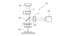
- FIG. 11 is an explanatory view showing the measuring device 31, and incident light reflected by the half mirror 33 from the laser 32 serving as a light source is irradiated to the sample 34 in the vertical direction and reflected from the sample 34 in the vertical direction.
- An optical path for guiding light to the light receiving element 35 through the half mirror 33 is formed, and it is not necessary to irradiate incident light obliquely, so that the apparatus 31 can be downsized.
- a fixed polarizer P is disposed between the laser 32 and the half mirror 33, and an analyzer A is rotatably disposed between the half mirror 33 and the light receiving element 35. Between the sample 34, a half-wave plate 36 that rotates linearly polarized light generated by the polarizer P is rotatably provided.
- the half-wave plate 36 is rotated 180 °, the incident direction of the linearly polarized light irradiated to the sample 34 is rotated 360 °. If the photon A is rotated 360 °, it is possible to detect the polarization state of the reflected light when the incident direction of the linearly polarized light applied to the sample is changed by 10 °. For example, if the reflected light intensity is measured every time the analyzer A is rotated by 10 °, 36 data are obtained in the relationship between the rotation angle ⁇ of the analyzer A and the reflected light intensity R, and Fourier analysis is performed based on this data. By performing the above, one phase difference data for the incident direction ⁇ of the linearly polarized light at this time can be obtained.
- JP 2008-76324 A Japanese Patent Laid-Open No. 11-304645
- the present invention aims to reduce the size of the entire apparatus by irradiating incident light perpendicularly to the sample, and at the same time, to measure the direction of the optical axis and the magnitude of anisotropy in a very short time. Is a technical issue.
- the present invention relates to the direction of the optical axis of the sample and the magnitude of the optical anisotropy based on the change in the polarization state of the incident light irradiated on the measurement area of the sample and the reflected light.
- an optical anisotropy parameter measuring apparatus for measuring Measurement optics that irradiates the measurement area with incident light from a laser as a light source through a half mirror in the vertical direction and guides reflected light reflected from the measurement area in the vertical direction to the light receiving element through the half mirror And an arithmetic processing unit that calculates an optical anisotropy parameter based on the reflected light intensity detected by the system and the light receiving element,
- a polarizer is disposed between the laser and the half mirror
- an analyzer is disposed between the half mirror and the light receiving element
- the polarization is interposed between the half mirror and the sample.
- a half-wave plate that is rotated to rotate the linearly polarized light generated by the optical element, and the direction of the slow axis is ⁇ ⁇ ( ⁇ ⁇ n ⁇ / 4) with respect to the slow axis of the half-wave plate.
- N is an integer) a quarter wavelength plate that is rotationally driven synchronously so that the rotation angle is doubled with respect to the half wavelength plate from the shifted initial position
- the arithmetic processing unit is configured to detect the reflected light intensity R (+ ⁇ ) detected when the quarter-wave plate is rotated synchronously with the half-wave plate from the initial position + ⁇ , and the quarter-wave plate to the initial position.
- a difference ⁇ R from the reflected light intensity R ( ⁇ ) detected when rotating in synchronization with the half-wave plate from ⁇ is calculated, and based on the relationship between the rotation angle of the linearly polarized light and the difference ⁇ R. It is characterized in that the direction of the optical axis of the sample and the magnitude of optical anisotropy are determined.
- the optical anisotropy measurement apparatus irradiates incident light in a vertical direction to the measurement area from a laser serving as a light source via a half mirror, and reflects reflected light reflected in the vertical direction from the measurement area.
- a measurement optical system that leads to the light receiving element via the half mirror is provided. Therefore, the incident light is irradiated in the vertical direction with respect to the sample, and not only the apparatus can be downsized but also the optical system does not need to be rotated as compared with the case where the incident light is irradiated obliquely. Therefore, it is not necessary to secure that space.
- the light emitted from the laser becomes linearly polarized light by a polarizer, the polarization axis of the linearly polarized light is rotated by a half-wave plate, and becomes elliptically polarized light by a quarter-wave plate arranged with a slow axis shifted by ⁇ ⁇ . It is converted and irradiated in a direction perpendicular to the sample.
- the polarized light component whose polarization state has not changed is returned to linearly polarized light when passing through the quarter-wave plate again, and when passing through the half-wave plate, the polarizer Since the linearly polarized light generated by the linear polarization is returned to the same linearly shaped light, the polarization component whose polarization state has been changed is cut by the analyzer having a crossed Nicols relationship with the polarizer. Therefore, the light passes through the analyzer and reaches the light receiving element, and can be detected as a change in light intensity. Since the polarization component of the reflected light from the sample surface having optical anisotropy changes, the light intensity change is detected according to the anisotropy.
- the reflected light intensity R ( ⁇ ) detected when rotating in synchronization with the half-wave plate from ⁇ is measured. That is, with respect to one measurement point, when the initial position of the quarter-wave plate is + ⁇ and when it is set to ⁇ , the half-wave plate is rotated 180 ° and at the same time, the quarter-wave plate The measurement is completed only by rotating 360 °.
- the difference ⁇ R R (+ ⁇ ) ⁇ R ( ⁇ ) of the reflected light intensity is calculated. That is, by taking the difference between the polarization states included in the reflected light of two elliptically polarized lights having a symmetric relationship, it is possible to extract only the change in the polarization state caused by the optical anisotropy of the sample. Based on the relationship between the rotation angle of the linearly polarized light and the difference ⁇ R, the direction of the optical axis of the sample and the magnitude of the optical anisotropy can be determined.
- the difference ⁇ R is 0 in the direction of the optical axis of the sample. Know the direction of the axis. Also, since the magnitude of the anisotropy is reflected in the amplitude in the height direction of the difference ⁇ R, it is possible to determine the magnitude of the optical anisotropy based on the magnitude of the maximum or minimum value of the difference. These optical anisotropy parameters can be measured very easily and in a short time.
- the difference exhibits a change approximating a sine curve with one cycle of 180 °, and takes a value of 0 every 90 °.
- the direction of the optical axis of the sample is 0 °
- the reflected light intensity is equal at 0 ° and 180 °
- the reflected light intensity is equal at 90 ° and 270 °. Therefore, the direction of the optical axis cannot be specified only from this data.
- the product test of the liquid crystal alignment film is to confirm the distribution state of the orientation direction (the direction of the optical axis) at a plurality of measurement points and the deviation from the direction of the alignment process. Since the direction is known and the deviation is about 20 ° at most, the direction of the optical axis is not mistaken by 90 °.
- Explanatory drawing which shows an example of the optical anisotropy parameter measuring apparatus which concerns on this invention.
- Explanatory drawing which shows the processing procedure.
- the graph which shows the measurement result by this invention method.
- the graph which shows distribution of the direction of an optical axis.
- the graph which shows distribution of an anisotropic magnitude
- the graph which shows the measurement result by the other method which concerns on this invention.
- the graph which shows the measurement result by the other method which concerns on this invention.
- Explanatory drawing which shows the other optical anisotropy parameter measuring apparatus which concerns on this invention.
- Explanatory drawing which shows the further another optical anisotropy parameter measuring apparatus which concerns on this invention.
- An object of the present invention is to reduce the size of the entire apparatus by irradiating incident light perpendicularly to a sample, and at the same time, to measure the direction of an optical axis and the magnitude of anisotropy in a very short time.
- incident light is irradiated in the vertical direction to the measurement area from the laser serving as the light source via the half mirror, and the reflected light reflected in the vertical direction from the measurement area is passed through the half mirror.
- a measurement optical system that leads to the light receiving element and an arithmetic processing unit that calculates an optical anisotropy parameter based on the reflected light intensity detected by the light receiving element are provided.
- a polarizer is arranged between the laser and the half mirror, an analyzer is arranged between the half mirror and the light receiving element, and the polarizer is generated between the half mirror and the sample.
- a quarter-wave plate that is rotationally driven synchronously so that the rotation angle is doubled with respect to the half-wave plate from the shifted initial position is disposed.
- the arithmetic processing unit detects the reflected light intensity R (+ ⁇ ) detected when the quarter-wave plate is rotated synchronously with the half-wave plate from the initial position + ⁇ and the quarter-wave plate at the initial position ⁇ .
- the difference ⁇ R between the reflected light intensity R ( ⁇ ) detected when rotating from ⁇ synchronously with the half-wave plate is calculated, and the sample is calculated based on the relationship between the rotation angle of the linearly polarized light and the difference ⁇ R.
- the direction of the optical axis and the magnitude of the optical anisotropy are determined.
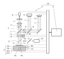
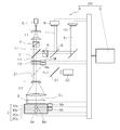
- the optical anisotropy parameter measuring apparatus 1 of the present example shown in FIG. 1 detects an optical anisotropy parameter at a measurement point (dotted measurement area) S on a sample 3 placed on a stage 2.
- This optical anisotropy parameter measuring apparatus 1 is based on the change of the polarization state of incident light irradiated to the measurement point S and the reflected light, and the direction of the optical axis and the magnitude of the optical anisotropy at the measurement point S.
- the measurement optical system 4 includes an incident optical path L 1 that irradiates incident light in a direction perpendicular to the measurement area S from the laser 6 serving as a light source via the half mirror 7, and reflected light that is reflected in the vertical direction from the measurement area S. the is branched through a half mirror 7, further a reflection light path L 2 guided to the light receiving element 9 is branched by the half mirror 8, the tilt detection light path L for guiding the light transmitted through the half mirror 8 on the two-dimensional optical position detecting element 10 3 is formed.
- a beam expander 11 and a polarizer P are arranged between the laser 6 and the half mirror 7 to expand the irradiation light into a parallel light beam, and between the half mirror 7 and the stage 2.
- the half-wave plate 12 rotated by the motor M 1 to rotate the linearly polarized light generated by the polarizer P, and the direction of the slow axis with respect to the slow axis of the half-wave plate 12 1 from the initial position shifted by ⁇ ⁇ ( ⁇ ⁇ n ⁇ / 4, where n is an integer) synchronously driven by the motor M 2 so that the rotation angle is doubled with respect to the half-wave plate 12.
- a / 4 wavelength plate 13 is arranged.
- a revolver 16 is provided between the quarter-wave plate 13 and the stage 2 and includes an objective-side condensing lens 14 that condenses incident light and a through-hole 15 that transmits the incident light as parallel light. However, it is arranged so that it can be rotated by the motor M 3 and can be moved up and down by the motor M 4 so that the incident light is focused on the surface of the sample 3 by the objective side condenser lens 14.
- the laser 6 is a semiconductor laser having a wavelength of 532 nm and a light intensity of 10 mW, and is expanded into a parallel light beam having a diameter of 5 mm by a beam expander 11 having a magnification of 10 times, and a Glan-Thompson prism having an extinction ratio of 10 ⁇ 6 is used.
- the sample P is transmitted through the polarizer P, transmitted through the objective-side condenser lens (manufactured by Olympus: magnification 50 times), and irradiated on the sample. At this time, the irradiation spot system to the sample is about 1 micron.
- the reflected light path L 2 the analyzer A is arranged between the half mirror 7 and 8, between the half mirror 8 and the light receiving element 9, after converging the reflected light at the focal point, the light receiving element while diffusing 9 is provided with a detection-side condensing lens 17 leading to a focal point, and a pinhole 18 is provided at the focal position thereof, so that noise light reflected from other than the focal position of the objective-side condensing lens 14 (for example, a sample) Can be removed.
- the detection-side condensing lens 17 having a focal length of 25 mm is used, the pin hole 18 having a hole diameter of 20 ⁇ m is transmitted, and the light intensity of the reflected light is detected by the light receiving element 9 formed of a photomultiplier tube.
- the stage 2 can be tilted in the ⁇ x and ⁇ y directions to adjust the tilt of the sample 2 and the X table 19x and the Y table 19y that can move in the X axis and Y axis directions orthogonal to the optical axis Z of the incident light.
- each table is driven by a motor M 5 ⁇ M 8.
- the polarization axis of the polarizer P is oriented parallel to the X-axis direction
- the slow axis of the half-wave plate 12 is oriented in the direction that coincides with the polarization axis at the initial position
- the quarter-wave plate The position where the slow axis of 13 is shifted by ⁇ ⁇ ( ⁇ ⁇ n ⁇ / 4, where n is an integer) with respect to the slow axis of the half-wave plate 12 is set as an initial position
- the polarization axis of the analyzer A is Y It will be oriented parallel to the axis.
- the polarization axis of the polarizer P and the slow axis of the half-wave plate 12 are directed in the X-axis direction, and the slow axis of the quarter-wave plate 13 is + ⁇ or ⁇ directed to ⁇ .
- the rotation angle of the linearly polarized light incident on the quarter-wave plate 13 is defined by the rotation angle of the polarization axis.
- the rotation angle of the half-wave plate 12 is ⁇
- the half-wave plate 12 is transmitted through the quarter-wave plate 13.
- the rotation angle of the polarization axis of the linearly polarized light incident on is expressed by 2 ⁇ .
- the 1 ⁇ 4 wavelength plate 13 is rotated from the initial position ⁇ ⁇ so as to have a rotation angle twice that of the 1 ⁇ 2 wavelength plate 12, the rotation angle is expressed by 2 ⁇ ⁇ ⁇ , and the incident linearly polarized light Since the slow axis is always shifted by ⁇ ⁇ ( ⁇ ⁇ n ⁇ / 4, where n is an integer), the light transmitted through the quarter-wave plate 13 becomes elliptically polarized light.
- the elliptically polarized light is irradiated onto the sample by rotating the azimuth corresponding to the major axis of the ellipse by 360 ° while maintaining the ellipticity constant.
- An observation half mirror 21 that can advance and retreat on the optical axis is disposed between the quarter-wave plate 13 and the revolver 16, and an illuminated imaging camera 22 that observes the sample 3 is disposed on the reflected optical axis.
- the measurement optical system 4 can be accommodated in a housing (not shown) having a diameter of about 100 mm, and the conventional optical system requires a diameter of 600 mm including the operating range. The size could be reduced by a factor of one.
- the arithmetic processing unit 5 has a light receiving element 9, a two-dimensional light position detecting element 10, and an imaging camera 22 connected to its input port, and motors M 1 to M 8 connected to its output port.
- the tilt adjustment of the sample 3 the positioning of the measurement point S in the XY plane, the measurement of the position of the measurement point S in the Z-axis direction, the initial position setting and driving of the half-wave plate 12 and the quarter-wave plate 13, light reception
- the reflected light intensity data measured by the element 9 is stored, and the optical anisotropy parameter is calculated.
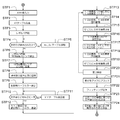
- FIG. 2 is a flowchart showing a series of processing procedures by the arithmetic processing unit 5.
- a sample whose optical anisotropy is to be measured is set on the stage 2 and the main switch is turned on, power is supplied to the arithmetic processing unit 5, the laser 6, the light receiving element 9, the motors M 1 to M 8, and the like. The following processing is started.
- step STP1 when the XY coordinates of the measurement point S are input in step STP1, the motors M 5 and M 6 are driven in step STP2, and the measurement point S is made to coincide with the incident optical axis Z by the XY tables 19x and 19y.
- step STP4 tilt adjustment means
- the reflected light of the optical axis tilt detection from the sample 3 by the two-dimensional light position detecting element 10 in step STP4 determines whether or not to coincide with the optical axis of the optical path L 3, if they do not match
- [theta] x drives the motor M 7, M 8 at step STP5
- [theta] y table 20x by adjusting the tilt of the sample 3 by 20y
- step STP6 rotates the revolver 16 is advanced the objective side condenser lens 14 to the incident light axis Z and the condenser lens 14 to scan the incident direction of the optical axis Z at step STP7, the light receiving element in the step STP8
- the position of the condenser lens 14 is fixed at a position where the light receiving intensity 9 is maximized, the Z coordinate at that time is stored, and the process proceeds to step STP9.
- step STP9 the observation half mirror 21 is advanced on the optical axis Z, and in step STP10, the image analysis of the imaging camera 22 is performed to determine whether or not the incident optical axis Z matches the measurement point S. If not, finely adjust the XY tables 19x and 19y in step STP11 and return to step STP10. If irradiated, store the XYZ coordinates in step STP12, retract the observation half mirror 21, and proceed to step STP13. To do.
- step STP 14 the motor M 1, M 2 by the rotation angle of the quarter-wave plate 13 is synchronously driven so as to be twice the angle of rotation ⁇ of the half-wave plate 12, the step STP15.
- the reflected light intensity is measured by the light receiving element 9, and the rotation angle of the linearly polarized light transmitted through the half-wave plate 12, that is, the rotation angle of the half-wave plate 12.
- the reflected light intensity R (+ ⁇ ) is stored so as to correspond to an angle twice as large as. Then, the measurement is interrupted when the half-wave plate 12 is rotated by 180 ° in step STP16.
- the slow axis of the half-wave plate 12 is parallel to the X-axis by the motor M 1 in step STP17, the motor M 2 toward the - ⁇ slow axis of the quarter wave plate 13 with respect to the X axis To reset the initial position.
- step STP18 the motor M 1, M 2 by the rotation angle of the quarter-wave plate 13 is synchronously driven so as to be twice the angle of rotation ⁇ of the half-wave plate 12, the step STP19 Then, every time the half-wave plate 12 is rotated by a predetermined angle until the half-wave plate 12 is rotated by 180 °, the reflected light intensity is measured by the light receiving element 9, and the rotation angle of the linearly polarized light transmitted through the half-wave plate 12, that is, the half wavelength
- the reflected light intensity R ( ⁇ ) is stored in correspondence with an angle twice the rotation angle of the plate 12.
- the sample 3 is set on the stage 2 with the direction of 0 ° directed as necessary, the sample 3 is set on the stage 2 with the direction of 90 ° directed. It is also effective to perform the processing of steps STP13 to STP20 in the case where an isotropic material such as glass having no optical anisotropy is set on the stage 2.
- Each reflected light intensity R in this case is expressed as follows.
- step STP21 the difference ⁇ R with respect to the rotation angle 2 ⁇ of linearly polarized light is plotted on the graph, and the fitting process is performed in step STP22 to draw a graph of 2 ⁇ R diagram.
- step STP24 by calculating values reflecting the amplitude in the height direction of ⁇ R, such as the difference between the maximum value and the minimum value of ⁇ R, the height from 0 to the maximum value, the magnitude of anisotropy is obtained. Be evaluated.
- an LCD TFT substrate (30 microns per pixel) coated with an alignment liquid crystal alignment film is set on the stage 2 with the direction of the alignment process parallel to the X axis, and used for an objective lens.
- the automatic rotation revolver is rotated, and adjustment is performed based on the signal of the optical position detection element with the objective lens removed from the optical path.
- the objective-side condenser lens 14 is inserted into the incident optical axis Z, and the condenser lens 14 is scanned in the Z direction. If the position of the condenser lens 14 is fixed at a position where the intensity at the light receiving element 9 is maximized and the Z coordinate at that time is stored, the position in the Z direction of the measurement point S can be measured. Next, after adjusting the XY tables 19x and 19y according to the image of the imaging camera 22 so that incident light is irradiated into the pixels of the TFT substrate, the reflected light intensity is measured.
- the initial position of the half-wave plate 12 is set so that the slow axis is parallel to the X axis, and the slow axis of the quarter wavelength plate 13 is shifted by + ⁇ (+ 2 °) from the X axis.
- the half-wave plate 12 and the quarter-wave plate 13 are rotated at rotation speeds of 20 rpm and 40 rpm, respectively, so that the rotation angle of the quarter-wave plate is doubled with respect to the half-wave plate 12.
- the reflected light intensity R (+ ⁇ ) is read by the light receiving element 9 every time the half-wave plate 12 rotates 5 ° from 0 to 180 °.
- the light emitted from the laser 6 travels along the incident optical path L 1 , becomes linearly polarized light with the polarizer P having a polarization axis parallel to the X-axis direction, and is polarized by the half-wave plate 12 with the linearly polarized light.
- the axis is rotated and converted into elliptically polarized light by a quarter-wave plate 13 arranged with a slow axis shifted by + 2 °, and is narrowed down to a spot with a diameter of 1 micron by the objective side condensing lens 14 to the sample 3. Irradiate vertically.
- the reflected light diffused from the measurement point S of the sample 3 travels along the reflected light path L 2 , is collimated by the objective side condensing lens 14, and is again the quarter wavelength plate 13 and the half wavelength plate 12.
- Is converted to linearly polarized light reflected by the half mirror 7, transmitted through the analyzer A, reflected by the half mirror 8, and placed at the focal position of the detection-side condenser lens 17.
- noise light reflected from other than the focal position of the objective-side condenser lens 14 (for example, back-surface reflected light of the sample) is removed, and only the reflected light reflected from the measurement point S reaches the light receiving element 9.
- the polarization component whose polarization state has not changed is returned to linearly polarized light when passing through the quarter-wave plate 13 again, and passes through the half-wave plate 12.
- the polarization axis is returned to the linearly knitted light parallel to the X axis, so that the polarization component whose polarization state has been changed is the original linearly polarized light, while the polarization axis is cut by the analyzer A parallel to the Y axis. Since the polarization states are different, the light passes through the analyzer A and reaches the light receiving element 9, and can be detected as a change in light intensity.
- the initial position of the half-wave plate 12 is set so that the slow axis is parallel to the X axis, and the slow axis of the quarter wavelength plate 13 is ⁇ ( ⁇ 2 °) with respect to the X axis.
- the reflected light intensity R ( ⁇ ) is similarly measured by the light receiving element 9.
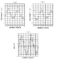
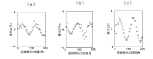
- ⁇ R R (+ ⁇ ) ⁇ R ( ⁇ ) 3 (a) to 3 (c) are graphs showing the measurement results at this time.
- the horizontal axis is the rotation angle 2 ⁇ of linearly polarized light rotated by the half-wave plate 12, and the vertical axis is 3A shows the reflected light intensity R (+ ⁇ ), FIG. 3B shows the reflected light intensity R ( ⁇ ), and FIG. 3C shows the difference ⁇ R.
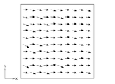
- FIG. 4 is a graph showing the result of measuring the direction of the optical axis at a large number of measurement points set on the surface of the sample 3 on the matrix
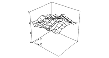
- FIG. 5 is a graph showing the distribution of the magnitude of anisotropy. .
- the case where the sample 3 is set on the stage 2 with the 0 ° direction oriented and the sample 3 in the 90 ° direction are removed as necessary. If the reflected light intensity is measured for the case where it is set on the stage 2 and the case where an optically isotropic material such as glass having no optical anisotropy is set on the stage 2 and the difference is calculated as follows, The optical anisotropy parameter can be measured with high accuracy.
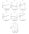
- FIG. 6 shows reflected light intensities R 0 (+ ⁇ ) and R 0 ( ⁇ ) from the sample 3 set on the stage 2 with the alignment treatment direction parallel to the X axis (0 ° direction), and optical on the stage 2.
- ⁇ R [R 0 (+ ⁇ ) ⁇ R 0 ( ⁇ )] ⁇ [R E (+ ⁇ ) ⁇ R E ( ⁇ )]
- FIG. 6A shows the reflected light intensity R 0 (+ ⁇
- FIG. 6B shows the reflected light intensity R 0 ( ⁇ )
- FIG. 6C shows the difference [R 0 (+ ⁇ ) ⁇ R 0 ( ⁇ ⁇ )]
- FIG. 6D shows the reflected light intensity R E (+ ⁇ )
- FIG. 6E shows the reflected light intensity R E ( ⁇ )
- FIG. 6F shows the difference [R E (+ ⁇ ) ⁇ R. E ( ⁇ )]
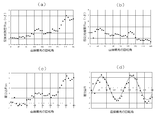
- FIG. 7 shows the reflected light intensities R 0 (+ ⁇ ) and R 0 ( ⁇ ) from the sample 3 set on the stage 2 with the alignment processing direction parallel to the X axis (0 ° direction) and the alignment processing direction.
- the difference ⁇ R is calculated by the following equation: It is a measurement result when doing.
- ⁇ R [R 0 (+ ⁇ ) ⁇ R 0 ( ⁇ )] ⁇ [R 90 (+ ⁇ ) ⁇ R 90 ( ⁇ )]
- the reflected light intensities R 0 (+ ⁇ ), R 0 ( ⁇ ), R E (+ ⁇ ), and R E ( ⁇ ) are based on the data shown in FIGS. 6 (a), (b), (d), and (e).
- the intensities R 90 (+ ⁇ ) and R 90 ( ⁇ ) the data shown in FIGS. 7A and 7B were used.
- FIG. 8A shows the difference ⁇ R 0
- FIG. 8B shows the difference ⁇ R 90.
- FIG. 9 is an explanatory view showing another optical anisotropy parameter measuring apparatus according to the present invention.
- the optical anisotropy parameter measuring device 25 of this example can evaluate the optical anisotropy of the entire measurement area S 2 (for example, a diameter of 10 mm) having a certain size.
- symbol is attached to the part which overlaps with FIG. 1, and detailed description is abbreviate
- the beam expander 11 interposed between the laser 6 and the half mirror 7 of the measuring optical system 4 the size of the beam diameter of incident light corresponding to the measurement area S 2 (e.g., diameter 10 mm)
- the magnification is set so as to obtain a parallel light beam.
- the objective side condenser lens 14, the detection side condenser lens 17, and the pinhole 18 in FIG. 1 are not provided.
- the incident light that has become a parallel light beam having a diameter of 10 mm by the beam expander 11 passes through the polarizer P, the half-wave plate 12 and the quarter-wave plate 13 and becomes elliptically polarized light. It is of the irradiation to the entire measurement area S 2.
- the reflected light passes through the quarter-wave plate 13 and the half-wave plate 12 as a parallel light beam having a diameter of 10 mm, passes through the analyzer A along the reflected light path L 2 , and reaches the light receiving element 9. The light intensity is measured.
- the direction of the optical axis of the measurement area S 2 thereof average direction is detected, if the uniform direction of the optical axis larger value H indicating the size of the anisotropy in the direction of the optical axis If there is variation, the value H indicating the magnitude of anisotropy decreases.
- FIG. 10 is an explanatory view showing still another optical anisotropy parameter measuring apparatus according to the present invention. Portions which are the same as those in FIG. Optical anisotropy parameter measurement device 26 of this example, the measurement area S 3 If (for example, about a diameter 1m) is set larger than the diameter of the wave plates 12 and 13 but, once the entire measuring area S 3 Optical anisotropy can be evaluated by measurement.
- the measurement area S 3 If (for example, about a diameter 1m) is set larger than the diameter of the wave plates 12 and 13 but, once the entire measuring area S 3 Optical anisotropy can be evaluated by measurement.
- a beam expander 11 is disposed between the laser 6 of the measurement optical system 4 and the half mirror 7 so that the irradiation light is a parallel light beam having a predetermined light beam diameter (for example, 5 mm).
- the beam expander 27 whose diameter increases in the parallel beam with a size of a light flux diameter in accordance with incident light to the measurement area S 3 is interposed.
- the objective side condenser lens 14, the detection side condenser lens 17, and the pinhole 18 in FIG. 1 are not provided.
- the incident light that has become a parallel light beam of 5 mm by the first beam expander 11 passes through the polarizer P, the half-wave plate 12 and the quarter-wave plate 13 to become elliptically polarized light, and the beam expander.
- the panda 27 expands the beam into a parallel light beam having a diameter of 1 m and irradiates the entire measurement area S 2 of the sample 3.
- the reflected light becomes a parallel light beam having a diameter of 1 m, travels in the reverse direction to the beam expander 27, becomes a parallel light beam having a diameter of 5 mm, and passes through the quarter-wave plate 13 and the half-wave plate 12.
- the analyzer a transmitted through the analyzer a along the reflected light path L 2, reaches the light receiving element 9, the light intensity is measured.
- the direction of the optical axis of the measurement area S 2 thereof average direction is detected, if the uniform direction of the optical axis larger value H indicating the size of the anisotropy, if there is variation in different
- the point where the value H indicating the magnitude of the directivity is small is the same as in the previous embodiment.
- the present invention can be applied to products having optical anisotropy, in particular, quality inspection of liquid crystal alignment films.
- Optical Anisotropy Parameter Measurement Device 2 Stage 3 Sample S Measurement Point (Measurement Area) 4 Measurement optical system 5
- Arithmetic processing device 6 Laser 7 Half mirror 9
- Light receiving element P Polarizer A
- Two-dimensional light position detecting element 12 1/2 wavelength plate 13 1/4 wavelength plate 14
- Objective side condensing lens 17 Detection side Condenser lens 18 pinhole
Landscapes
- Physics & Mathematics (AREA)
- Health & Medical Sciences (AREA)
- Life Sciences & Earth Sciences (AREA)
- Chemical & Material Sciences (AREA)
- Analytical Chemistry (AREA)
- Biochemistry (AREA)
- General Health & Medical Sciences (AREA)
- General Physics & Mathematics (AREA)
- Immunology (AREA)
- Pathology (AREA)
- Investigating Or Analysing Materials By Optical Means (AREA)
Priority Applications (2)
| Application Number | Priority Date | Filing Date | Title |
|---|---|---|---|
| KR1020137025210A KR101594982B1 (ko) | 2011-04-11 | 2012-04-05 | 광학 이방성 파라미터 측정 장치, 측정 방법 및 측정용 프로그램 |
| CN201280017649.3A CN103477206B (zh) | 2011-04-11 | 2012-04-05 | 光学异向性参数测量装置、测量方法及测量用系统 |
Applications Claiming Priority (2)
| Application Number | Priority Date | Filing Date | Title |
|---|---|---|---|
| JP2011087655A JP5806837B2 (ja) | 2011-04-11 | 2011-04-11 | 光学異方性パラメータ測定装置、測定方法及び測定用プログラム |
| JP2011-087655 | 2011-04-11 |
Publications (2)
| Publication Number | Publication Date |
|---|---|
| WO2012141061A2 true WO2012141061A2 (ja) | 2012-10-18 |
| WO2012141061A3 WO2012141061A3 (ja) | 2012-12-06 |
Family
ID=47009779
Family Applications (1)
| Application Number | Title | Priority Date | Filing Date |
|---|---|---|---|
| PCT/JP2012/059314 Ceased WO2012141061A2 (ja) | 2011-04-11 | 2012-04-05 | 光学異方性パラメータ測定装置、測定方法及び測定用プログラム |
Country Status (5)
| Country | Link |
|---|---|
| JP (1) | JP5806837B2 (enExample) |
| KR (1) | KR101594982B1 (enExample) |
| CN (1) | CN103477206B (enExample) |
| TW (1) | TWI545309B (enExample) |
| WO (1) | WO2012141061A2 (enExample) |
Cited By (1)
| Publication number | Priority date | Publication date | Assignee | Title |
|---|---|---|---|---|
| CN115236047A (zh) * | 2017-05-23 | 2022-10-25 | 浜松光子学株式会社 | 取向特性测定方法、取向特性测定程序及取向特性测定装置 |
Families Citing this family (12)
| Publication number | Priority date | Publication date | Assignee | Title |
|---|---|---|---|---|
| JP6087751B2 (ja) * | 2013-07-05 | 2017-03-01 | 株式会社モリテックス | 光学異方性パラメータ測定装置、測定方法及び測定用プログラム |
| JP2015143650A (ja) * | 2014-01-31 | 2015-08-06 | セイコーエプソン株式会社 | 旋光計測方法及び旋光計測装置 |
| TWI542864B (zh) * | 2014-12-30 | 2016-07-21 | 財團法人工業技術研究院 | 異向性量測系統、異向性量測方法及其校正方法 |
| KR101675694B1 (ko) | 2015-09-11 | 2016-11-23 | 성균관대학교산학협력단 | 블록 인기도에 기반한 ssd의 블록 교체방법 |
| WO2017094495A1 (ja) * | 2015-12-03 | 2017-06-08 | 浜松ホトニクス株式会社 | 検査装置及び検査方法 |
| KR101704936B1 (ko) | 2015-12-07 | 2017-02-09 | 성균관대학교산학협력단 | 블록의 우선성에 기반한 ssd의 블록 교체방법 및 이를 적용하는 하이브리드 저장 시스템 |
| CN105675541B (zh) * | 2016-01-13 | 2018-10-26 | 中国科学院苏州生物医学工程技术研究所 | 一种具有轴向高分辨率的反射式共聚焦系统 |
| JP2018187143A (ja) * | 2017-05-09 | 2018-11-29 | ソニー株式会社 | 光学定数測定装置及び光学定数測定方法 |
| WO2018216246A1 (ja) * | 2017-05-23 | 2018-11-29 | 浜松ホトニクス株式会社 | 配向特性測定方法、配向特性測定プログラム、及び配向特性測定装置 |
| CN109141828B (zh) * | 2018-07-19 | 2020-08-28 | 中国科学院上海光学精密机械研究所 | 液晶器件相位调控特性测量装置和测量方法 |
| KR102486442B1 (ko) | 2019-06-07 | 2023-01-09 | 주식회사 엘지화학 | 편광판의 액정얼룩 검사장치 및 편광판의 액정얼룩 검사방법 |
| KR20200129033A (ko) * | 2020-03-03 | 2020-11-17 | 주식회사 코엠에스 | 반도체 기판 보호필름 박리 여부 감시 장치 및 방법 |
Family Cites Families (11)
| Publication number | Priority date | Publication date | Assignee | Title |
|---|---|---|---|---|
| JP2956688B1 (ja) * | 1998-04-24 | 1999-10-04 | 日本電気株式会社 | 異方性薄膜評価方法および評価装置 |
| JP3610837B2 (ja) * | 1998-09-18 | 2005-01-19 | 株式会社日立製作所 | 試料表面の観察方法及びその装置並びに欠陥検査方法及びその装置 |
| JP2001083042A (ja) * | 1999-09-13 | 2001-03-30 | Nec Corp | 光学的異方性の測定方法、測定装置及び測定方法を記録した記録媒体 |
| JP3535786B2 (ja) * | 1999-12-03 | 2004-06-07 | Necエレクトロニクス株式会社 | 液晶表示素子評価法及び評価装置 |
| JP2004294293A (ja) * | 2003-03-27 | 2004-10-21 | Neoark Corp | 複数の異なる試料の光学特性を一括して観察・測定する方法 |
| JP4663529B2 (ja) * | 2005-01-24 | 2011-04-06 | 株式会社モリテックス | 光学的異方性パラメータ測定方法及び測定装置 |
| KR101280335B1 (ko) * | 2005-01-24 | 2013-07-01 | 가부시키가이샤 모리텍스 | 광학적 이방성 파라미터 측정 방법 및 측정 장치 |
| JP4921090B2 (ja) * | 2006-09-25 | 2012-04-18 | 株式会社モリテックス | 光学異方性パラメータ測定方法及び測定装置 |
| CN100507478C (zh) * | 2007-06-01 | 2009-07-01 | 清华大学 | 可溯源测量任意波片位相延迟的方法和装置 |
| JP5198980B2 (ja) * | 2008-09-02 | 2013-05-15 | 株式会社モリテックス | 光学異方性パラメータ測定方法及び測定装置 |
| CN101963495A (zh) * | 2009-07-24 | 2011-02-02 | 瀚宇彩晶股份有限公司 | 测量各向异性物质的物理参数的装置及方法 |
-
2011
- 2011-04-11 JP JP2011087655A patent/JP5806837B2/ja not_active Expired - Fee Related
-
2012
- 2012-04-05 KR KR1020137025210A patent/KR101594982B1/ko not_active Expired - Fee Related
- 2012-04-05 CN CN201280017649.3A patent/CN103477206B/zh not_active Expired - Fee Related
- 2012-04-05 WO PCT/JP2012/059314 patent/WO2012141061A2/ja not_active Ceased
- 2012-04-09 TW TW101112439A patent/TWI545309B/zh not_active IP Right Cessation
Cited By (1)
| Publication number | Priority date | Publication date | Assignee | Title |
|---|---|---|---|---|
| CN115236047A (zh) * | 2017-05-23 | 2022-10-25 | 浜松光子学株式会社 | 取向特性测定方法、取向特性测定程序及取向特性测定装置 |
Also Published As
| Publication number | Publication date |
|---|---|
| JP5806837B2 (ja) | 2015-11-10 |
| TW201250228A (en) | 2012-12-16 |
| KR20140011346A (ko) | 2014-01-28 |
| TWI545309B (zh) | 2016-08-11 |
| WO2012141061A3 (ja) | 2012-12-06 |
| JP2012220381A (ja) | 2012-11-12 |
| CN103477206B (zh) | 2015-11-25 |
| CN103477206A (zh) | 2013-12-25 |
| KR101594982B1 (ko) | 2016-02-17 |
Similar Documents
| Publication | Publication Date | Title |
|---|---|---|
| JP5806837B2 (ja) | 光学異方性パラメータ測定装置、測定方法及び測定用プログラム | |
| US8009292B2 (en) | Single polarizer focused-beam ellipsometer | |
| TWI421486B (zh) | 光學異方性參數測定方法及測定裝置 | |
| TWI591322B (zh) | Birefringence measurement apparatus, birefringence measurement method, film inspection apparatus, and film inspection method | |
| CN115165758A (zh) | 一种检测设备及方法 | |
| US8547557B2 (en) | Apparatus for determining a height map of a surface through both interferometric and non-interferometric measurements | |
| CN110702614B (zh) | 一种椭偏仪装置及其检测方法 | |
| CN107843564A (zh) | 一种反射式光学材料非线性偏振光谱测量装置 | |
| JPH11173946A (ja) | 光学的特性測定装置 | |
| TWI384213B (zh) | 光學異向性參數測量方法及測量裝置 | |
| JP4663529B2 (ja) | 光学的異方性パラメータ測定方法及び測定装置 | |
| JP2011127993A (ja) | レンズ検査装置及びレンズ検査方法 | |
| JP4728830B2 (ja) | 光学的異方性パラメータ測定方法及び測定装置 | |
| CN117890342A (zh) | 微区多功能荧光光波导特性检测成像装置及测试方法 | |
| TWI482958B (zh) | 偵測裝置及偵測方法 | |
| TWI542864B (zh) | 異向性量測系統、異向性量測方法及其校正方法 | |
| TWI814412B (zh) | 多方向物件失效檢查系統及其方法 | |
| CN119620558B (zh) | 一种光学处理设备及其工作方法 | |
| JP7753471B2 (ja) | 光学検査対象物の検査装置及び光学検査対象物の検査方法 | |
| JP2001083042A (ja) | 光学的異方性の測定方法、測定装置及び測定方法を記録した記録媒体 | |
| TW202223455A (zh) | 檢查方法 | |
| TW200839224A (en) | Polarizer inspection device |
Legal Events
| Date | Code | Title | Description |
|---|---|---|---|
| 121 | Ep: the epo has been informed by wipo that ep was designated in this application |
Ref document number: 12771169 Country of ref document: EP Kind code of ref document: A2 |
|
| ENP | Entry into the national phase |
Ref document number: 20137025210 Country of ref document: KR Kind code of ref document: A |
|
| NENP | Non-entry into the national phase |
Ref country code: DE |
|
| 122 | Ep: pct application non-entry in european phase |
Ref document number: 12771169 Country of ref document: EP Kind code of ref document: A2 |