WO2012137867A1 - 架構 - Google Patents
架構 Download PDFInfo
- Publication number
- WO2012137867A1 WO2012137867A1 PCT/JP2012/059356 JP2012059356W WO2012137867A1 WO 2012137867 A1 WO2012137867 A1 WO 2012137867A1 JP 2012059356 W JP2012059356 W JP 2012059356W WO 2012137867 A1 WO2012137867 A1 WO 2012137867A1
- Authority
- WO
- WIPO (PCT)
- Prior art keywords
- plate
- frame
- fuel pump
- sliding plate
- reinforcing member
- Prior art date
- Legal status (The legal status is an assumption and is not a legal conclusion. Google has not performed a legal analysis and makes no representation as to the accuracy of the status listed.)
- Ceased
Links
Images


Classifications
-
- F—MECHANICAL ENGINEERING; LIGHTING; HEATING; WEAPONS; BLASTING
- F02—COMBUSTION ENGINES; HOT-GAS OR COMBUSTION-PRODUCT ENGINE PLANTS
- F02F—CYLINDERS, PISTONS OR CASINGS, FOR COMBUSTION ENGINES; ARRANGEMENTS OF SEALINGS IN COMBUSTION ENGINES
- F02F7/00—Casings, e.g. crankcases
- F02F7/0021—Construction
- F02F7/0034—Built from sheet material and welded casings
-
- F—MECHANICAL ENGINEERING; LIGHTING; HEATING; WEAPONS; BLASTING
- F02—COMBUSTION ENGINES; HOT-GAS OR COMBUSTION-PRODUCT ENGINE PLANTS
- F02F—CYLINDERS, PISTONS OR CASINGS, FOR COMBUSTION ENGINES; ARRANGEMENTS OF SEALINGS IN COMBUSTION ENGINES
- F02F7/00—Casings, e.g. crankcases
-
- F—MECHANICAL ENGINEERING; LIGHTING; HEATING; WEAPONS; BLASTING
- F02—COMBUSTION ENGINES; HOT-GAS OR COMBUSTION-PRODUCT ENGINE PLANTS
- F02B—INTERNAL-COMBUSTION PISTON ENGINES; COMBUSTION ENGINES IN GENERAL
- F02B77/00—Component parts, details or accessories, not otherwise provided for
-
- F—MECHANICAL ENGINEERING; LIGHTING; HEATING; WEAPONS; BLASTING
- F02—COMBUSTION ENGINES; HOT-GAS OR COMBUSTION-PRODUCT ENGINE PLANTS
- F02F—CYLINDERS, PISTONS OR CASINGS, FOR COMBUSTION ENGINES; ARRANGEMENTS OF SEALINGS IN COMBUSTION ENGINES
- F02F1/00—Cylinders; Cylinder heads
-
- F—MECHANICAL ENGINEERING; LIGHTING; HEATING; WEAPONS; BLASTING
- F16—ENGINEERING ELEMENTS AND UNITS; GENERAL MEASURES FOR PRODUCING AND MAINTAINING EFFECTIVE FUNCTIONING OF MACHINES OR INSTALLATIONS; THERMAL INSULATION IN GENERAL
- F16M—FRAMES, CASINGS OR BEDS OF ENGINES, MACHINES OR APPARATUS, NOT SPECIFIC TO ENGINES, MACHINES OR APPARATUS PROVIDED FOR ELSEWHERE; STANDS; SUPPORTS
- F16M1/00—Frames or casings of engines, machines or apparatus; Frames serving as machinery beds
-
- F—MECHANICAL ENGINEERING; LIGHTING; HEATING; WEAPONS; BLASTING
- F02—COMBUSTION ENGINES; HOT-GAS OR COMBUSTION-PRODUCT ENGINE PLANTS
- F02F—CYLINDERS, PISTONS OR CASINGS, FOR COMBUSTION ENGINES; ARRANGEMENTS OF SEALINGS IN COMBUSTION ENGINES
- F02F7/00—Casings, e.g. crankcases
- F02F2007/0097—Casings, e.g. crankcases for large diesel engines
Definitions
- the present invention relates to a frame constituting a large diesel engine for marine use.
- FIG. 5 of Patent Document 1 As a frame constituting a large diesel engine for marine use, for example, one disclosed in FIG. 5 of Patent Document 1, that is, one that supports one sliding plate 6 with two partition walls 7 is known. Yes.
- FIGS. 5 and 6 In recent years, in order to reduce the weight of the entire frame, as shown in FIGS. 5 and 6, a frame that supports a single sliding plate 53 with a single partition wall 51 and two reinforcing members 52. 54 is put into practical use.
- the frame 54 having the configuration shown in FIGS. 5 and 6, that is, in the frame 54 in which the reinforcing member 52 is welded to both the partition wall 51 and the sliding plate 53 the number of welding points increases and welding is performed. Therefore, there is a problem that the work process and work time are increased and workability is poor.
- the present invention has been made in view of the above circumstances, and can improve workability and reduce deformation of the sliding plate due to side forces transmitted to the sliding plate via the cross head.
- the purpose is to provide a frame that can be used.
- the present invention employs the following means in order to solve the above problems.
- the frame according to the first aspect of the present invention is located on the fuel pump side and the exhaust side of the first plate that partitions the cylinders and forms the central portion in the width direction, and the first plate, A partition provided with a second plate forming a fuel pump side portion and an exhaust side portion; and a sliding plate disposed between the first plate and the second plate for guiding the crosshead;
- the sliding plates located adjacent to each other on the fuel pump side or the sliding plates located adjacent to each other on the exhaust side are connected by a reinforcing member.
- the frame according to the second aspect of the present invention is located on the fuel pump side and the exhaust side of the first plate that partitions the cylinders and forms the central portion in the width direction, and the first plate,
- a partition provided with a second plate forming a fuel pump side portion and an exhaust side portion; and a sliding plate disposed between the first plate and the second plate for guiding the crosshead;
- the sliding plates located adjacent to each other on the fuel pump side and the sliding plates located adjacent to each other on the exhaust side are connected by a reinforcing member.
- the reinforcing member is disposed at a central portion in the height direction of the frame.
- the reinforcing member is provided at the central portion (more specifically, in the height direction of the frame). Is slightly higher than the center), that is, it does not interfere with the connecting rod that swings during operation (does not interfere with the movement of the connecting rod that swings during operation), and is also attached to the sliding plate via the crosshead. It is fixed at a position where the transmitted side force can be received most efficiently (the deformation of the sliding plate due to the side force is most reduced). As a result, the deformation of the sliding plate due to the side force transmitted to the sliding plate via the cross head can be further reduced, and the per contact of the cross head against the sliding plate can be further reduced. The uneven wear of the head and the sliding plate can be further reduced.
- the reinforcing member arranged on the fuel pump side and the reinforcing member arranged on the exhaust side are provided at positions facing each other in the height direction of the frame. Also good.
- a plate-like member or the like on which a worker can ride is hung on the reinforcing members that face each other in the height direction of the frame, for example (for example, (located above the frame) It can be used as a scaffolding for workers when maintaining a piston rod gland packing or the like provided under the jacket.
- the diesel engine according to the third aspect of the present invention includes any one of the above frames.
- transformation of the sliding plate by the side force transmitted to a sliding plate via a crosshead can be reduced. It has. Thereby, the manufacturing cost can be reduced and the reliability of the diesel engine can be improved.
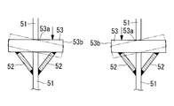
- FIG. 2 It is a longitudinal cross-sectional view which shows the structural example of the large sized diesel engine which comprised the frame which concerns on one Embodiment of this invention. It is a perspective view of the frame concerning one embodiment of the present invention. It is the figure which expanded the principal part seeing FIG. 2 from upper direction. It is the figure which expanded the principal part seeing FIG. 2 from upper direction, Comprising: It is a figure for demonstrating the effect of this invention. It is the figure which expanded the principal part seeing the conventional frame from upper direction, Comprising: It is a figure similar to FIG. It is the figure which expanded the principal part seeing the conventional frame from the top, Comprising: It is a figure for demonstrating the effect of the conventional frame.
- 1 is a longitudinal sectional view showing a structural example of a large diesel engine equipped with a frame according to the present embodiment
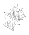
- FIG. 2 is a perspective view of the frame according to the present embodiment
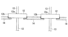
- FIG. 3 is a perspective view of FIG. 2 viewed from above.
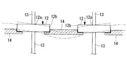
- FIG. 4 is an enlarged view
- FIG. 4 is an enlarged view of the main part when FIG. 2 is viewed from above, and is a view for explaining the function and effect of the present invention.
- a large diesel engine 1 shown in FIG. 1 is a crosshead type diesel engine typically used as a main engine for ship propulsion, and includes a base plate 2 positioned below and a frame ( A main body) 3 and a jacket 4 provided on the frame 3.
- the base plate 2, the frame 3, and the jacket 4 are integrally fastened and fixed by a plurality of tie bolts (not shown) extending in the vertical direction.
- the jacket 4 is provided with a cylinder liner 5, and a cylinder cover 6 is provided at the upper end of the cylinder liner 5.
- the piston 7 is provided in the space formed by the cylinder liner 5 and the cylinder cover 6 so that reciprocation is possible.
- the upper end of piston rod 8 is attached to the lower end of piston 7 so that rotation is possible.
- the base plate 2 is a crankcase and is provided with a crankshaft 9. Moreover, the lower end of the connecting rod 10 is connected to the upper end of the crankshaft 9 so that rotation is possible.
- the frame 3 is provided with a cross head 11 that rotatably connects the piston rod 8 and the connecting rod 10. That is, the lower end of the piston rod 8 and the upper end of the connecting rod 10 are connected to the cross head 11.
- a pair of sliding plates 12 extending in the vertical direction are provided on both sides (the left side and the right side in FIG. 1) of the cross head 11 in a state of being fixed to the frame 3 side.
- the sliding plate 12 is fixed to the partition wall 13 of the frame 3. That is, the sliding plate 12 has a fixed end 12a that is one side end thereof fixed to the partition wall 13 and is erected toward the other side end. Note that the other end is a free end 12 b that is not fixed to the partition wall 13.
- the sliding plates 12 located adjacent to each other on the fuel pump side are connected by the reinforcing member 14. Yes.
- the reinforcing member 14 is a plate-like member that has a convex shape in a top view (bottom view) and a rectangular shape (rectangular view) in a front view (rear view), and is adjacent to the sliding plate 12 that is located on the fuel pump side. (The surface opposite to the surface on which the crosshead 11 (see FIG. 1) slides: the surface opposite to the exhaust side) is fixed by welding. Further, as shown in FIG.
- the reinforcing member 14 does not interfere with the central portion (more specifically, slightly above the center) in the height direction of the frame 3, that is, the connecting rod 10 that swings during operation. (Does not interfere with the movement of the connecting rod 10 that swings during operation) and receives the side force transmitted to the sliding plate 12 through the cross head 11 most efficiently (deformation of the sliding plate 12 by the side force). It is fixed at a position where it can be reduced most.
- the free ends 12 b of the adjacent sliding plates 12 are joined together by welding, and the deformation (movement: shake) of the free ends 12 b occurs.
- the deformation of the sliding plate 12 due to the side force (the force indicated by the solid line arrow in FIG. 4) transmitted to the sliding plate 12 via the cross head 11 (see FIG. 1) can be reduced.
- the contact of the cross head 11 with the plate 12 can be reduced, and uneven wear of the cross head 11 and the sliding plate 12 can be reduced.
- the reinforcing member 14 has a central portion (more specifically, slightly above the center) in the height direction of the frame 3, that is, the connecting rod 10 that swings during operation. (See FIG. 1) without interfering with (does not interfere with the movement of the connecting rod 10 that swings during operation) and receives the side force transmitted to the sliding plate 12 via the crosshead 11 most efficiently ( It is fixed at a position where the deformation of the sliding plate 12 due to the side force can be reduced most. Thereby, the deformation
- the sliding plate by the side force transmitted to the sliding plate 12 via the crosshead 11
- the frame 3 which can reduce the deformation
- the present invention is not limited to the above-described embodiments, and various changes and modifications can be made without departing from the gist of the present invention.
- the side opposite to the fuel pump side opposite side
- Only the adjacent sliding plates 12 positioned on the exhaust side may be connected by the reinforcing member 14, or positioned adjacent to the adjacent sliding plates 12 positioned on the fuel pump side and on the exhaust side.
- both the adjacent sliding plates 12 may be connected by the reinforcing member 14.
- a piston rod gland packing (not shown) provided at the lower part of the jacket 4 (arranged above the frame 3) is formed by spanning a plate-like member that can be ridden and serving as a scaffold for workers. ) Etc. can be maintained safely and easily.
- the sliding plate 12 and the connecting member 14 are joined by welding.
- the present invention is not limited to this, and fastening of bolts and nuts (not shown) or the like is possible. You may make it connect using a means. Thereby, the welding location and the location where the distortion caused by welding can be corrected can be further reduced, the working process and the working time can be further reduced, and the workability can be further improved.
- each Two or more may be arranged on the fuel pump side of the cylinder, or two or more may be arranged on the exhaust side of each cylinder.
- the reinforcing member 14 swings in the vicinity of 1/3 and 2/3 in the frame height direction, that is, during operation.
Landscapes
- Engineering & Computer Science (AREA)
- General Engineering & Computer Science (AREA)
- Mechanical Engineering (AREA)
- Chemical & Material Sciences (AREA)
- Combustion & Propulsion (AREA)
- Cylinder Crankcases Of Internal Combustion Engines (AREA)
- Fuel-Injection Apparatus (AREA)
Abstract
作業性を向上させることができるとともに、クロスヘッドを介して摺動板に伝達されるサイドフォースによる摺動板の変形を低減させることができる架構を提供する。シリンダ間を仕切るとともに、幅方向における中央部分を形成する第1の板と、この第1の板の燃料ポンプ側および排気側にそれぞれ位置して、燃料ポンプ側部分および排気側部分を形成する第2の板とを備えた隔壁(13)と、前記第1の板と前記第2の板との間に配置されて、クロスヘッドをガイドする摺動板(12)とを備えた架構(3)であって、燃料ポンプ側に位置して隣り合う前記摺動板(12)同士、または排気側に位置して隣り合う前記摺動板(12)同士を、補強部材(14)により連結した。
Description
本発明は、舶用等の大型ディーゼルエンジンを構成する架構に関するものである。
舶用等の大型ディーゼルエンジンを構成する架構としては、例えば、特許文献1の図5に開示されたもの、すなわち、二枚の隔壁7で一枚の摺動板6を支持するものが知られている。
また、近年では、架構全体の軽量化を図るため、図5および図6に示すような、一枚の隔壁51と二枚の補強部材52とで、一枚の摺動板53を支持する架構54が実用化されている。
しかしながら、図5および図6に示すような構成を有する架構54、すなわち、補強部材52が、隔壁51および摺動板53の双方に溶接接合された架構54では、溶接箇所が多くなるとともに、溶接による歪みを補正しなければならず、作業工程および作業時間が増加し、作業性が悪いといった問題点があった。
しかしながら、図5および図6に示すような構成を有する架構54、すなわち、補強部材52が、隔壁51および摺動板53の双方に溶接接合された架構54では、溶接箇所が多くなるとともに、溶接による歪みを補正しなければならず、作業工程および作業時間が増加し、作業性が悪いといった問題点があった。
また、図5および図6に示すような構成を有する架構54、すなわち、摺動板53の一側端である固定端53aが隔壁51に対して固定され、他側端が自由端53bとされている架構54では、図6に示すように、クロスヘッド(図示せず)を介して摺動板53に伝達されるサイドフォース(図6において実線矢印で示す力)による摺動板53の変形が大きくなる。そのため、クロスヘッドが摺動板53に片当たりして、クロスヘッドおよび摺動板53が偏摩耗してしまうといった問題点もあった。
本発明は、上記の事情に鑑みてなされたもので、作業性を向上させることができるとともに、クロスヘッドを介して摺動板に伝達されるサイドフォースによる摺動板の変形を低減させることができる架構を提供することを目的とする。
本発明は、上記課題を解決するため、以下の手段を採用した。
本発明の第1の態様に係る架構は、シリンダ間を仕切るとともに、幅方向における中央部分を形成する第1の板と、この第1の板の燃料ポンプ側および排気側にそれぞれ位置して、燃料ポンプ側部分および排気側部分を形成する第2の板とを備えた隔壁と、前記第1の板と前記第2の板との間に配置されて、クロスヘッドをガイドする摺動板とを備えた架構であって、燃料ポンプ側に位置して隣り合う前記摺動板同士、または排気側に位置して隣り合う前記摺動板同士が、補強部材により連結されている。
本発明の第1の態様に係る架構は、シリンダ間を仕切るとともに、幅方向における中央部分を形成する第1の板と、この第1の板の燃料ポンプ側および排気側にそれぞれ位置して、燃料ポンプ側部分および排気側部分を形成する第2の板とを備えた隔壁と、前記第1の板と前記第2の板との間に配置されて、クロスヘッドをガイドする摺動板とを備えた架構であって、燃料ポンプ側に位置して隣り合う前記摺動板同士、または排気側に位置して隣り合う前記摺動板同士が、補強部材により連結されている。
本発明の第2の態様に係る架構は、シリンダ間を仕切るとともに、幅方向における中央部分を形成する第1の板と、この第1の板の燃料ポンプ側および排気側にそれぞれ位置して、燃料ポンプ側部分および排気側部分を形成する第2の板とを備えた隔壁と、前記第1の板と前記第2の板との間に配置されて、クロスヘッドをガイドする摺動板とを備えた架構であって、燃料ポンプ側に位置して隣り合う前記摺動板同士、および排気側に位置して隣り合う前記摺動板同士が、補強部材により連結されている。
前記第1の態様に係る架構および前記第2の態様に係る架構によれば、例えば、図2から図4に示すように、隣り合う摺動板12の自由端12b同士のみが溶接により接合されることになる。
これにより、溶接箇所および溶接による歪みを補正する箇所を低減させることができ、作業工程および作業時間を低減させることができて、作業性を向上させることができる。
また、前記第1の態様に係る架構および前記第2の態様に係る架構によれば、例えば、図4に示すように、隣り合う摺動板12の自由端12b同士が溶接により接合され、自由端12bの変形(動き:振れ)が拘束されることになる。
これにより、クロスヘッドを介して摺動板12に伝達されるサイドフォース(図4において実線矢印で示す力)による摺動板12の変形を低減させることができ、摺動板12に対するクロスヘッドの片当たりを低減させることができて、クロスヘッドおよび摺動板12の偏摩耗を低減させることができる。
これにより、溶接箇所および溶接による歪みを補正する箇所を低減させることができ、作業工程および作業時間を低減させることができて、作業性を向上させることができる。
また、前記第1の態様に係る架構および前記第2の態様に係る架構によれば、例えば、図4に示すように、隣り合う摺動板12の自由端12b同士が溶接により接合され、自由端12bの変形(動き:振れ)が拘束されることになる。
これにより、クロスヘッドを介して摺動板12に伝達されるサイドフォース(図4において実線矢印で示す力)による摺動板12の変形を低減させることができ、摺動板12に対するクロスヘッドの片当たりを低減させることができて、クロスヘッドおよび摺動板12の偏摩耗を低減させることができる。
前記第1の態様または前記第2の態様にかかる架構において、前記補強部材は、当該架構の高さ方向における中央部に配置されているとさらに好適である。
このような架構によれば、補強部材が各シリンダの燃料ポンプ側に奇数本、および/または排気側に奇数本設けられている場合、補強部材は、架構の高さ方向における中央部(より詳しくは、中央よりも少し上)、すなわち、運転中に揺動する連接棒と干渉せず(運転中に揺動する連接棒の動きを妨げず)、かつ、クロスヘッドを介して摺動板に伝達されるサイドフォースを最も効率よく受ける(サイドフォースによる摺動板の変形を最も低減させる)ことができる位置に固定されていることになる。
これにより、クロスヘッドを介して摺動板に伝達されるサイドフォースによる摺動板の変形をさらに低減させることができ、摺動板に対するクロスヘッドの片当たりをさらに低減させることができて、クロスヘッドおよび摺動板の偏摩耗をさらに低減させることができる。
これにより、クロスヘッドを介して摺動板に伝達されるサイドフォースによる摺動板の変形をさらに低減させることができ、摺動板に対するクロスヘッドの片当たりをさらに低減させることができて、クロスヘッドおよび摺動板の偏摩耗をさらに低減させることができる。
前記第2の態様にかかる架構において、燃料ポンプ側に配置された前記補強部材と、排気側に配置された前記補強部材とは、当該架構の高さ方向において互いに対向する位置に設けられていてもよい。
このような架構によれば、当該架構の高さ方向において互いに対向する補強部材に、作業員が乗ることのできる板状の部材等を掛け渡して、例えば、(当該架構の上方に配置されている)ジャケットの下部に設けられたピストン棒グランドパッキン等をメンテナンスする際の作業員の足場とすることができる。
本発明の第3の態様に係るディーゼルエンジンは、上記いずれかの架構を具備している。
前記第3の態様に係るディーゼルエンジンによれば、作業性を向上させることができるとともに、クロスヘッドを介して摺動板に伝達されるサイドフォースによる摺動板の変形を低減させることができる架構を具備している。これにより、製造コストの低減化および当該ディーゼルエンジンの信頼性を向上させることができる。
本発明に係る架構によれば、作業性を向上させることができるとともに、クロスヘッドを介して摺動板に伝達されるサイドフォースによる摺動板の変形を低減させることができるという効果を奏する。
以下に、本発明の一実施形態に係る架構について、図1から図4を参照して説明する。
図1は本実施形態に係る架構を具備した大型ディーゼルエンジンの構造例を示す縦断面図、図2は本実施形態に係る架構の斜視図、図3は図2を上方から見て要部を拡大した図、図4は図2を上方から見て要部を拡大した図であって、本発明の作用効果を説明するための図である。
図1は本実施形態に係る架構を具備した大型ディーゼルエンジンの構造例を示す縦断面図、図2は本実施形態に係る架構の斜視図、図3は図2を上方から見て要部を拡大した図、図4は図2を上方から見て要部を拡大した図であって、本発明の作用効果を説明するための図である。
図1に示す大型ディーゼルエンジン1は、典型的には船舶推進用の主機として用いられるクロスヘッド型のディーゼルエンジンであり、下方に位置する台板2と、台板2上に設けられた架構(本体)3と、架構3上に設けられたジャケット4とを備えている。これら台板2、架構3、およびジャケット4は、上下方向に延在する複数のタイボルト(図示せず)によって一体的に締め付けられて固定されている。
ジャケット4にはシリンダライナ5が設けられており、このシリンダライナ5の上端にはシリンダカバー6が設けられている。そして、シリンダライナ5およびシリンダカバー6によって形成された空間内にピストン7が往復動可能に設けられている。また、ピストン7の下端には、ピストン棒8の上端が回動可能に取り付けられている。
台板2はクランクケースとされており、クランク軸9が設けられている。また、クランク軸9の上端には、連接棒10の下端が回動可能に接続されている。
架構3には、ピストン棒8と連接棒10とを回動可能に接続するクロスヘッド11が設けられている。すなわち、ピストン棒8の下端および連接棒10の上端がクロスヘッド11に接続されている。クロスヘッド11の両側(図1において左側および右側)には、上下方向に延在する一対の摺動板12が架構3の側に固定された状態で設けられている。
図2に示すように、摺動板12は、架構3の隔壁13に対して固定されている。すなわち、摺動板12は、その一側端である固定端12aが隔壁13に対して固定され、他側端に向かって立設されている。なお、他側端は、隔壁13に固定されていない自由端12bとされている。
また、本実施形態では、図2から図4に示すように、燃料ポンプ側に位置して隣り合う(燃料ポンプ側に隣接配置された)摺動板12同士が、補強部材14により連結されている。
補強部材14は、上面視(下面視)凸形状を呈し、正面視(背面視)矩形状(長方形状)を呈する板状の部材であり、燃料ポンプ側に位置して隣り合う摺動板12の外側(クロスヘッド11(図1参照)が摺動する面と反対側の面:排気側と反対側の面)に、溶接接合にて固定されている。また、図1に示すように、補強部材14は、架構3の高さ方向における中央部(より詳しくは、中央よりも少し上)、すなわち、運転中に揺動する連接棒10と干渉せず(運転中に揺動する連接棒10の動きを妨げず)、かつ、クロスヘッド11を介して摺動板12に伝達されるサイドフォースを最も効率よく受ける(サイドフォースによる摺動板12の変形を最も低減させる)ことができる位置に固定されている。
補強部材14は、上面視(下面視)凸形状を呈し、正面視(背面視)矩形状(長方形状)を呈する板状の部材であり、燃料ポンプ側に位置して隣り合う摺動板12の外側(クロスヘッド11(図1参照)が摺動する面と反対側の面:排気側と反対側の面)に、溶接接合にて固定されている。また、図1に示すように、補強部材14は、架構3の高さ方向における中央部(より詳しくは、中央よりも少し上)、すなわち、運転中に揺動する連接棒10と干渉せず(運転中に揺動する連接棒10の動きを妨げず)、かつ、クロスヘッド11を介して摺動板12に伝達されるサイドフォースを最も効率よく受ける(サイドフォースによる摺動板12の変形を最も低減させる)ことができる位置に固定されている。
本実施形態に係る架構3によれば、例えば、図2から図4に示すように、隣り合う摺動板12の自由端12b同士のみが溶接により接合されることになる。
これにより、溶接箇所および溶接による歪みを補正する箇所を低減させることができ、作業工程および作業時間を低減させることができて、作業性を向上させることができる。
これにより、溶接箇所および溶接による歪みを補正する箇所を低減させることができ、作業工程および作業時間を低減させることができて、作業性を向上させることができる。
また、本実施形態に係る架構3によれば、例えば、図4に示すように、隣り合う摺動板12の自由端12b同士が溶接により接合され、自由端12bの変形(動き:振れ)が拘束されることになる。
これにより、クロスヘッド11(図1参照)を介して摺動板12に伝達されるサイドフォース(図4において実線矢印で示す力)による摺動板12の変形を低減させることができ、摺動板12に対するクロスヘッド11の片当たりを低減させることができて、クロスヘッド11および摺動板12の偏摩耗を低減させることができる。
これにより、クロスヘッド11(図1参照)を介して摺動板12に伝達されるサイドフォース(図4において実線矢印で示す力)による摺動板12の変形を低減させることができ、摺動板12に対するクロスヘッド11の片当たりを低減させることができて、クロスヘッド11および摺動板12の偏摩耗を低減させることができる。
さらに、本実施形態に係る架構3によれば、補強部材14は、架構3の高さ方向における中央部(より詳しくは、中央よりも少し上)、すなわち、運転中に揺動する連接棒10(図1参照)と干渉せず(運転中に揺動する連接棒10の動きを妨げず)、かつ、クロスヘッド11を介して摺動板12に伝達されるサイドフォースを最も効率よく受ける(サイドフォースによる摺動板12の変形を最も低減させる)ことができる位置に固定されていることになる。
これにより、クロスヘッド11を介して摺動板12に伝達されるサイドフォースによる摺動板12の変形をさらに低減させることができ、摺動板12に対するクロスヘッド11の片当たりをさらに低減させることができて、クロスヘッド11および摺動板12の偏摩耗をさらに低減させることができる。
これにより、クロスヘッド11を介して摺動板12に伝達されるサイドフォースによる摺動板12の変形をさらに低減させることができ、摺動板12に対するクロスヘッド11の片当たりをさらに低減させることができて、クロスヘッド11および摺動板12の偏摩耗をさらに低減させることができる。
そして、本実施形態に係る架構3を具備した大型ディーゼルエンジン1によれば、作業性を向上させることができるとともに、クロスヘッド11を介して摺動板12に伝達されるサイドフォースによる摺動板12の変形を低減させることができる架構3を具備している。これにより、製造コストの低減化および当該ディーゼルエンジン1の信頼性を向上させることができる。
なお、本発明は上述した実施形態に限定されるものではなく、本発明の要旨を逸脱しない範囲で各種変更・変形が可能である。
例えば、上述した実施形態では、燃料ポンプ側に位置して隣り合う摺動板12同士のみが、補強部材14により連結されているが、燃料ポンプ側と反対の側(対向する側)、すなわち、排気側に位置して隣り合う摺動板12同士のみを、補強部材14により連結するようにしてもよいし、燃料ポンプ側に位置して隣り合う摺動板12同士、および排気側に位置して隣り合う摺動板12同士の双方を補強部材14により連結するようにしてもよい。
燃料ポンプ側に位置して隣り合う摺動板12同士、および排気側に位置して隣り合う摺動板12同士の双方を補強部材14により連結した場合、対向する補強部材14に、作業員が乗ることのできる板状の部材等を掛け渡して、作業員の足場とすることにより、(架構3の上方に配置されている)ジャケット4の下部に設けられたピストン棒グランドパッキン(図示せず)等を、安全、かつ、容易にメンテナンスすることができる。
例えば、上述した実施形態では、燃料ポンプ側に位置して隣り合う摺動板12同士のみが、補強部材14により連結されているが、燃料ポンプ側と反対の側(対向する側)、すなわち、排気側に位置して隣り合う摺動板12同士のみを、補強部材14により連結するようにしてもよいし、燃料ポンプ側に位置して隣り合う摺動板12同士、および排気側に位置して隣り合う摺動板12同士の双方を補強部材14により連結するようにしてもよい。
燃料ポンプ側に位置して隣り合う摺動板12同士、および排気側に位置して隣り合う摺動板12同士の双方を補強部材14により連結した場合、対向する補強部材14に、作業員が乗ることのできる板状の部材等を掛け渡して、作業員の足場とすることにより、(架構3の上方に配置されている)ジャケット4の下部に設けられたピストン棒グランドパッキン(図示せず)等を、安全、かつ、容易にメンテナンスすることができる。
また、上述した実施形態では、摺動板12と連結部材14とを溶接により接合するようにしたが、本発明はこれに限定されるものではなく、ボルト・ナット(図示せず)等の締結手段を用いて連結するようにしてもよい。
これにより、溶接箇所および溶接による歪みを補正する箇所をさらに低減させることができ、作業工程および作業時間をさらに低減させることができて、作業性をさらに向上させることができる。
これにより、溶接箇所および溶接による歪みを補正する箇所をさらに低減させることができ、作業工程および作業時間をさらに低減させることができて、作業性をさらに向上させることができる。
さらに、上述した実施形態では、補強部材14が各シリンダの燃料ポンプ側に1本ずつ配置されたものを一具体例として挙げて説明したが、本発明はこれに限定されるものではなく、各シリンダの燃料ポンプ側に2本以上ずつ配置してもよいし、各シリンダの排気側に2本以上ずつ配置してもよい。
なお、各シリンダの燃料ポンプ側および/または排気側に2本ずつ配置した場合、補強部材14は、架構の高さ方向における1/3近傍および2/3近傍、すなわち、運転中に揺動する連接棒と干渉せず(運転中に揺動する連接棒の動きを妨げず)、かつ、クロスヘッドを介して摺動板に伝達されるサイドフォースを最も効率よく受ける(サイドフォースによる摺動板の変形を最も低減させる)ことができる位置に固定されることになる。
なお、各シリンダの燃料ポンプ側および/または排気側に2本ずつ配置した場合、補強部材14は、架構の高さ方向における1/3近傍および2/3近傍、すなわち、運転中に揺動する連接棒と干渉せず(運転中に揺動する連接棒の動きを妨げず)、かつ、クロスヘッドを介して摺動板に伝達されるサイドフォースを最も効率よく受ける(サイドフォースによる摺動板の変形を最も低減させる)ことができる位置に固定されることになる。
1 大型ディーゼルエンジン
3 架構
11 クロスヘッド
12 摺動板
13 隔壁
14 補強部材
3 架構
11 クロスヘッド
12 摺動板
13 隔壁
14 補強部材
Claims (5)
- シリンダ間を仕切るとともに、幅方向における中央部分を形成する第1の板と、この第1の板の燃料ポンプ側および排気側にそれぞれ位置して、燃料ポンプ側部分および排気側部分を形成する第2の板とを備えた隔壁と、
前記第1の板と前記第2の板との間に配置されて、クロスヘッドをガイドする摺動板とを備えた架構であって、
燃料ポンプ側に位置して隣り合う前記摺動板同士、または排気側に位置して隣り合う前記摺動板同士が、補強部材により連結されている架構。 - シリンダ間を仕切るとともに、幅方向における中央部分を形成する第1の板と、この第1の板の燃料ポンプ側および排気側にそれぞれ位置して、燃料ポンプ側部分および排気側部分を形成する第2の板とを備えた隔壁と、
前記第1の板と前記第2の板との間に配置されて、クロスヘッドをガイドする摺動板とを備えた架構であって、
燃料ポンプ側に位置して隣り合う前記摺動板同士、および排気側に位置して隣り合う前記摺動板同士が、補強部材により連結されている架構。 - 前記補強部材は、当該架構の高さ方向における中央部に配置されている請求項1または2に記載の架構。
- 燃料ポンプ側に配置された前記補強部材と、排気側に配置された前記補強部材とは、当該架構の高さ方向において互いに対向する位置に設けられている請求項2に記載の架構。
- 請求項1から4のいずれか一項に記載の架構を具備しているディーゼルエンジン。
Priority Applications (2)
| Application Number | Priority Date | Filing Date | Title |
|---|---|---|---|
| CN201280004386.2A CN103299058B (zh) | 2011-04-07 | 2012-04-05 | 构架 |
| KR1020137016762A KR101431409B1 (ko) | 2011-04-07 | 2012-04-05 | 엔진 프레임 |
Applications Claiming Priority (2)
| Application Number | Priority Date | Filing Date | Title |
|---|---|---|---|
| JP2011-085566 | 2011-04-07 | ||
| JP2011085566A JP5709621B2 (ja) | 2011-04-07 | 2011-04-07 | 架構 |
Publications (1)
| Publication Number | Publication Date |
|---|---|
| WO2012137867A1 true WO2012137867A1 (ja) | 2012-10-11 |
Family
ID=46969257
Family Applications (1)
| Application Number | Title | Priority Date | Filing Date |
|---|---|---|---|
| PCT/JP2012/059356 Ceased WO2012137867A1 (ja) | 2011-04-07 | 2012-04-05 | 架構 |
Country Status (4)
| Country | Link |
|---|---|
| JP (1) | JP5709621B2 (ja) |
| KR (1) | KR101431409B1 (ja) |
| CN (1) | CN103299058B (ja) |
| WO (1) | WO2012137867A1 (ja) |
Cited By (1)
| Publication number | Priority date | Publication date | Assignee | Title |
|---|---|---|---|---|
| CN113187620A (zh) * | 2020-01-10 | 2021-07-30 | 日本发动机股份有限公司 | 构架 |
Families Citing this family (1)
| Publication number | Priority date | Publication date | Assignee | Title |
|---|---|---|---|---|
| JP5984497B2 (ja) * | 2012-05-11 | 2016-09-06 | 株式会社神戸製鋼所 | 運転室昇降装置 |
Citations (3)
| Publication number | Priority date | Publication date | Assignee | Title |
|---|---|---|---|---|
| JPS60131143A (ja) * | 1983-12-17 | 1985-07-12 | Mitsubishi Heavy Ind Ltd | クロスヘッド形エンジンのピストン芯出し方法 |
| JP2007211786A (ja) * | 2007-05-18 | 2007-08-23 | Man Diesel As | エンジンフレーム構造 |
| JP2010223220A (ja) * | 2009-03-20 | 2010-10-07 | Waertsilae Schweiz Ag | 大型クロスヘッド・ディーゼル・エンジン |
Family Cites Families (5)
| Publication number | Priority date | Publication date | Assignee | Title |
|---|---|---|---|---|
| DE3512347C1 (de) * | 1985-04-01 | 1986-10-30 | Gebrüder Sulzer AG, Winterthur | Ständer mit einer Abstützung der Kreuzkopfgleitbahnen |
| DK171284B1 (da) * | 1992-11-24 | 1996-08-19 | Man B & W Diesel Gmbh | Totakts forbrændingsmotor af krydshovedtypen |
| EP1382829B1 (de) * | 2002-07-15 | 2008-10-29 | Wärtsilä Schweiz AG | Kreuzkopf-Grossdieselmotor |
| US7219642B1 (en) * | 2006-02-10 | 2007-05-22 | Gm Global Technology Operations, Inc. | Powertrain assembly and integral truss oil pan therefor |
| KR101419328B1 (ko) * | 2007-06-18 | 2014-07-14 | 베르트질레 슈바이츠 악티엔게젤샤프트 | 대형 크로스헤드 디젤 엔진 |
-
2011
- 2011-04-07 JP JP2011085566A patent/JP5709621B2/ja not_active Expired - Fee Related
-
2012
- 2012-04-05 WO PCT/JP2012/059356 patent/WO2012137867A1/ja not_active Ceased
- 2012-04-05 KR KR1020137016762A patent/KR101431409B1/ko not_active Expired - Fee Related
- 2012-04-05 CN CN201280004386.2A patent/CN103299058B/zh not_active Expired - Fee Related
Patent Citations (3)
| Publication number | Priority date | Publication date | Assignee | Title |
|---|---|---|---|---|
| JPS60131143A (ja) * | 1983-12-17 | 1985-07-12 | Mitsubishi Heavy Ind Ltd | クロスヘッド形エンジンのピストン芯出し方法 |
| JP2007211786A (ja) * | 2007-05-18 | 2007-08-23 | Man Diesel As | エンジンフレーム構造 |
| JP2010223220A (ja) * | 2009-03-20 | 2010-10-07 | Waertsilae Schweiz Ag | 大型クロスヘッド・ディーゼル・エンジン |
Cited By (2)
| Publication number | Priority date | Publication date | Assignee | Title |
|---|---|---|---|---|
| CN113187620A (zh) * | 2020-01-10 | 2021-07-30 | 日本发动机股份有限公司 | 构架 |
| CN113187620B (zh) * | 2020-01-10 | 2023-01-31 | 日本发动机股份有限公司 | 构架 |
Also Published As
| Publication number | Publication date |
|---|---|
| JP5709621B2 (ja) | 2015-04-30 |
| CN103299058A (zh) | 2013-09-11 |
| JP2012219698A (ja) | 2012-11-12 |
| KR101431409B1 (ko) | 2014-08-19 |
| KR20130086260A (ko) | 2013-07-31 |
| CN103299058B (zh) | 2015-09-16 |
Similar Documents
| Publication | Publication Date | Title |
|---|---|---|
| JP5709621B2 (ja) | 架構 | |
| KR102146229B1 (ko) | 실린더 재킷 및 크로스헤드식 내연 기관 | |
| JP5665488B2 (ja) | クロスヘッド型ディーゼル機関のクロスヘッド | |
| JP2012219699A (ja) | シリンダジャケット | |
| KR101422140B1 (ko) | 크로스헤드 유니플로우 연소기관 | |
| JP5511302B2 (ja) | エンジンの架構及びその製造方法 | |
| KR101413335B1 (ko) | 프레임 | |
| JP4005550B2 (ja) | エンジンフレーム構造 | |
| JP2004044591A (ja) | クロスヘッド大型ディーゼル・エンジン | |
| KR101419328B1 (ko) | 대형 크로스헤드 디젤 엔진 | |
| JP2012107583A (ja) | クロスヘッド型ディーゼル機関のクロスヘッド | |
| JP7047460B2 (ja) | ラダーフレーム | |
| CN110030108B (zh) | 用于内燃机的梯形框架 | |
| US10156253B2 (en) | Connecting rod of engine | |
| JP2006348859A (ja) | 内燃機関のシリンダブロック | |
| JP2011127536A (ja) | ディーゼルエンジン | |
| CN107087422A (zh) | 发动机底座 | |
| JP2007211786A (ja) | エンジンフレーム構造 | |
| JPH0736112Y2 (ja) | エンジンのシリンダブロック補強装置 | |
| JP6408026B2 (ja) | エンジンブロックおよびこれを備える内燃機関 | |
| JP2001289114A (ja) | ディーゼルエンジン | |
| JPH05340420A (ja) | 多気筒エンジンの本体構造 | |
| JPS5881590A (ja) | 舶用デイ−ゼルエンジンの下部架構溶接方法 | |
| JP2015161242A (ja) | 補強構造、これを備えた舶用エンジン、および船舶 | |
| JP2009114985A (ja) | 内燃機関のシリンダブロック |
Legal Events
| Date | Code | Title | Description |
|---|---|---|---|
| 121 | Ep: the epo has been informed by wipo that ep was designated in this application |
Ref document number: 12768641 Country of ref document: EP Kind code of ref document: A1 |
|
| ENP | Entry into the national phase |
Ref document number: 20137016762 Country of ref document: KR Kind code of ref document: A |
|
| NENP | Non-entry into the national phase |
Ref country code: DE |
|
| 122 | Ep: pct application non-entry in european phase |
Ref document number: 12768641 Country of ref document: EP Kind code of ref document: A1 |