WO2012137822A1 - 単結晶引上げ装置の結晶保持機構および単結晶インゴット製造方法 - Google Patents
単結晶引上げ装置の結晶保持機構および単結晶インゴット製造方法 Download PDFInfo
- Publication number
- WO2012137822A1 WO2012137822A1 PCT/JP2012/059203 JP2012059203W WO2012137822A1 WO 2012137822 A1 WO2012137822 A1 WO 2012137822A1 JP 2012059203 W JP2012059203 W JP 2012059203W WO 2012137822 A1 WO2012137822 A1 WO 2012137822A1
- Authority
- WO
- WIPO (PCT)
- Prior art keywords
- single crystal
- ingot
- crystal
- holding mechanism
- support
- Prior art date
- Legal status (The legal status is an assumption and is not a legal conclusion. Google has not performed a legal analysis and makes no representation as to the accuracy of the status listed.)
- Ceased
Links
Images





Classifications
-
- C—CHEMISTRY; METALLURGY
- C30—CRYSTAL GROWTH
- C30B—SINGLE-CRYSTAL GROWTH; UNIDIRECTIONAL SOLIDIFICATION OF EUTECTIC MATERIAL OR UNIDIRECTIONAL DEMIXING OF EUTECTOID MATERIAL; REFINING BY ZONE-MELTING OF MATERIAL; PRODUCTION OF A HOMOGENEOUS POLYCRYSTALLINE MATERIAL WITH DEFINED STRUCTURE; SINGLE CRYSTALS OR HOMOGENEOUS POLYCRYSTALLINE MATERIAL WITH DEFINED STRUCTURE; AFTER-TREATMENT OF SINGLE CRYSTALS OR A HOMOGENEOUS POLYCRYSTALLINE MATERIAL WITH DEFINED STRUCTURE; APPARATUS THEREFOR
- C30B15/00—Single-crystal growth by pulling from a melt, e.g. Czochralski method
- C30B15/32—Seed holders, e.g. chucks
-
- C—CHEMISTRY; METALLURGY
- C30—CRYSTAL GROWTH
- C30B—SINGLE-CRYSTAL GROWTH; UNIDIRECTIONAL SOLIDIFICATION OF EUTECTIC MATERIAL OR UNIDIRECTIONAL DEMIXING OF EUTECTOID MATERIAL; REFINING BY ZONE-MELTING OF MATERIAL; PRODUCTION OF A HOMOGENEOUS POLYCRYSTALLINE MATERIAL WITH DEFINED STRUCTURE; SINGLE CRYSTALS OR HOMOGENEOUS POLYCRYSTALLINE MATERIAL WITH DEFINED STRUCTURE; AFTER-TREATMENT OF SINGLE CRYSTALS OR A HOMOGENEOUS POLYCRYSTALLINE MATERIAL WITH DEFINED STRUCTURE; APPARATUS THEREFOR
- C30B15/00—Single-crystal growth by pulling from a melt, e.g. Czochralski method
- C30B15/30—Mechanisms for rotating or moving either the melt or the crystal
-
- C—CHEMISTRY; METALLURGY
- C30—CRYSTAL GROWTH
- C30B—SINGLE-CRYSTAL GROWTH; UNIDIRECTIONAL SOLIDIFICATION OF EUTECTIC MATERIAL OR UNIDIRECTIONAL DEMIXING OF EUTECTOID MATERIAL; REFINING BY ZONE-MELTING OF MATERIAL; PRODUCTION OF A HOMOGENEOUS POLYCRYSTALLINE MATERIAL WITH DEFINED STRUCTURE; SINGLE CRYSTALS OR HOMOGENEOUS POLYCRYSTALLINE MATERIAL WITH DEFINED STRUCTURE; AFTER-TREATMENT OF SINGLE CRYSTALS OR A HOMOGENEOUS POLYCRYSTALLINE MATERIAL WITH DEFINED STRUCTURE; APPARATUS THEREFOR
- C30B29/00—Single crystals or homogeneous polycrystalline material with defined structure characterised by the material or by their shape
- C30B29/02—Elements
- C30B29/06—Silicon
-
- Y—GENERAL TAGGING OF NEW TECHNOLOGICAL DEVELOPMENTS; GENERAL TAGGING OF CROSS-SECTIONAL TECHNOLOGIES SPANNING OVER SEVERAL SECTIONS OF THE IPC; TECHNICAL SUBJECTS COVERED BY FORMER USPC CROSS-REFERENCE ART COLLECTIONS [XRACs] AND DIGESTS
- Y10—TECHNICAL SUBJECTS COVERED BY FORMER USPC
- Y10T—TECHNICAL SUBJECTS COVERED BY FORMER US CLASSIFICATION
- Y10T117/00—Single-crystal, oriented-crystal, and epitaxy growth processes; non-coating apparatus therefor
- Y10T117/10—Apparatus
- Y10T117/1024—Apparatus for crystallization from liquid or supercritical state
- Y10T117/1032—Seed pulling
Definitions
- the present invention relates to a crystal holding mechanism of a single crystal pulling apparatus and a method of manufacturing a single crystal ingot, and more specifically, pulling of a single crystal ingot by the Czochralski method, particularly a single crystal pulling apparatus suitable for a large weight
- the present invention relates to a method for producing a single crystal ingot.
- single crystal silicon ingots are grown by the Czochralski method (CZ method).
- CZ method first, a polycrystalline silicon lump filled in a quartz crucible is melted by heating with a heater to obtain a silicon melt. Thereafter, the lower end portion of the seed crystal attached to the seed holder is immersed in a silicon melt, and the seed holder is gradually lifted upward while rotating the seed holder and the crucible to grow a single crystal silicon ingot on the lower end of the seed crystal.
- the dash neck method is adopted.
- the diameter of the seed crystal after immersion is narrowed down to form a neck portion having a diameter of about 3 mm continuously with the seed crystal, and dislocation is released to the surface of the neck portion.
- the pulling speed of the seed crystal is appropriately reduced, and the shoulder portion and the straight body portion of the ingot are pulled up sequentially.
- single crystal silicon ingots have been increased in diameter and length in order to improve device production efficiency and yield. As a result, the weight of the ingot increased, and pulling of the single crystal ingot only by the conventional dash-neck method could break the neck portion, and there was a possibility that safe ingots could not be grown.
- Patent Document 1 is known as a conventional technique for solving this problem.
- an engagement portion in which an enlarged diameter portion and a reduced diameter portion (constriction portion) are formed immediately below the neck portion is formed, and the engagement portion is mechanically held by a holding member of a holding mechanism.
- the load of the ingot is transferred from the neck portion to the gripping mechanism, and the lack of strength of the neck portion is compensated.
- the contact between the gripping member and the engaging portion becomes a point contact or a line contact with a short contact width, and stress per unit area against the ingot is concentrated, and the ingot breaks at the gripping portion of the engaging portion. Dislocation occurred. When the ingot completely broke during the growth of the single crystal ingot, there was a risk of causing a major accident of dropping the ingot.
- Patent Document 1 an attachment member made of a heat-resistant soft material that is plastically deformed when subjected to an ingot load is provided in a contact portion with the engaging portion of the gripping member.
- the attachment member comes into close contact with the uneven portion of the ingot.
- the contact area of a holding member and an engaging part becomes large, and the stress concentration per unit area with respect to an ingot is relieved.
- the present inventors have determined that a support that can freely be deformed within the elastic deformation region of the material and that can be used repeatedly is in contact with the reduced diameter portion of the gripping member of the crystal holding mechanism. It was found that all the above-mentioned problems could be solved if it was provided in the portion, and the present invention was completed.
- An object is to provide a crystal holding mechanism of a single crystal pulling apparatus and a method of manufacturing a single crystal ingot.
- This invention is formed when a seed crystal immersed in a melt in a crucible is pulled up to grow a single crystal ingot, and is formed between a neck portion continuous with the seed crystal and an upper portion of the single crystal ingot, and has an enlarged diameter.
- the crystal holding mechanism of the single crystal pulling apparatus for holding the single crystal ingot by holding the engaging portion composed of the portion and the reduced diameter portion continuous with the enlarged diameter portion using a holding member, It is a crystal holding mechanism of a single crystal pulling apparatus in which a holding member made of a linear spring that elastically supports the engaging portion is provided on a gripping member.
- a strand is formed by twisting a plurality of strands
- the linear spring is constituted by a wire rope formed by twisting a plurality of strands.
- the gripping member is formed with a long hole penetrating the upper and lower surfaces spaced apart from each other, and the wire rope is attached to the winding core formed between the paired long holes. It is desirable that the support is formed in a coil shape by being wound a plurality of times so as to have an elliptical shape that is long in the vertical direction and the upper end portion protrudes from the upper surface of the winding core portion.
- a single crystal ingot when a single crystal ingot is grown by pulling up a seed crystal immersed in a melt in a crucible, the single crystal ingot is grown while holding the single crystal ingot by a crystal holding mechanism.
- an engagement portion composed of an enlarged diameter portion and a reduced diameter portion continuous with the enlarged diameter portion is formed between a neck portion continuous with the seed crystal and an upper portion of the single crystal ingot.
- the crystal holding mechanism includes a gripping member for gripping the engaging portion provided with a support made of a linear spring that elastically supports the engaging portion, and after forming the engaging portion, In the method for producing a single crystal ingot, the engagement portion is elastically supported by the support body by holding the engagement portion by the holding member, and the single crystal ingot is grown in this state.
- the single crystal ingot is pulled up from the melt by the Czochralski method.
- part or all of the load (self-weight) of the single crystal ingot is transferred from the neck to the crystal holding mechanism, and the load on the single crystal ingot by the neck is reduced. Is done.
- the engaging portion (reduced diameter portion) of the single crystal ingot is supported by the gripping member via the corresponding support. Therefore, the support is deformed (elastically deformed) by the action of the load of the single crystal ingot so that the contact area with the engaging portion is increased within the elastically deformed region of the linear spring. This contact area increases as the load of the single crystal ingot increases.
- the support is not plastically deformed but is composed of a linear spring that can be reconstructed in the elastic deformation region. Therefore, it is also supported when another single crystal ingot is grown sequentially after growing a single crystal ingot or when a single crystal ingot is regrown due to the dislocation of the single crystal ingot during the growth. It can be reused multiple times without replacing the body with a new one. As a result, the maintenance cost of the crystal holding mechanism can be reduced.
- a long hole is formed in the gripping member so as to pass through the upper and lower surfaces, and the wire rope is formed in an elliptical shape that is long in the vertical direction at the winding core portion between the long holes, and the upper end.
- the support may be formed in a coil shape by being wound a plurality of times so that the portion protrudes from the upper surface of the winding core portion.
- the wire rope is wound so that the support protrudes from the upper surface of the gripping claw portion, so that an elastic deformation action due to the deformation of the coil shape is also obtained. As a result, local stress concentration at the contact site can be further suppressed.
- This invention is formed when a seed crystal immersed in a melt in a crucible is pulled up to grow a single crystal ingot, and is formed between a neck portion continuous with the seed crystal and an upper portion of the single crystal ingot, and has an enlarged diameter.
- the crystal holding mechanism of the single crystal pulling apparatus for holding the single crystal ingot by holding the engaging portion composed of the portion and the reduced diameter portion continuous with the enlarged diameter portion using a holding member, It is a crystal holding mechanism of a single crystal pulling apparatus in which a holding member made of a linear spring that elastically supports the engaging portion is provided on a gripping member.
- a single crystal ingot when a single crystal ingot is grown by pulling up a seed crystal immersed in a melt in a crucible, the single crystal is grown while holding the single crystal ingot by a crystal holding mechanism.
- an engagement portion composed of a diameter-enlarged portion and a diameter-reduced portion continuous to the diameter-enlarged portion is formed between a neck portion continuous to the seed crystal and an upper portion of the single crystal ingot.
- the crystal holding mechanism includes a gripping member that grips the engaging portion provided with a support made of a linear spring that elastically supports the engaging portion, and after forming the engaging portion,
- the engagement portion is elastically supported by the support body by holding the engagement portion by a holding member, and the single crystal ingot is grown in this state.
- the support body is pulled by the load of the single crystal ingot when the engagement portion is gripped.
- the deformation is performed so that the contact area with the engaging portion increases.
- the stress per unit area acting on the contact portion with the gripping member is reduced, and it is possible to prevent the single crystal ingot from breaking and dislocation from the gripping portion of the engaging portion.
- the support is not plastically deformed, but is composed of a linear spring whose shape can be restored within the elastic deformation region.
- the single crystal ingot for example, single crystal silicon can be employed.
- sapphire single crystal, ferrite single crystal, single crystal silicon for solar cells, and the like may be used.
- the single crystal pulling apparatus various Czochralski-type single crystal pulling apparatuses can be employed.
- an MCZ method in which a single crystal ingot is pulled up in a state where a high magnetic field is applied may be used.
- the term “between the neck portion and the upper portion of the single crystal ingot” as used herein refers to the range from the neck portion to the shoulder portion of the single crystal ingot with reference to the neck portion directly below the seed crystal, or directly from the neck portion. The range up to the top of the torso.
- the support member elastically supporting the engaging portion on the gripping member means that the supporting body is deformed so that the contact area with the engaging portion is increased by the action of the load of the single crystal ingot,
- the engaging portion is elastically supported by a support made of a linear spring.
- the load of a single crystal ingot acts so as to crush the coil from the radial direction of the coil, thereby increasing the contact area with the engaging portion of the support.
- the engaging portion is a abacus-shaped bulging portion of the abacus arranged above the single crystal ingot obtained by adjusting the pulling speed of the seed crystal.
- the engagement part is a frustoconical diameter-enlarged part having a diameter larger than that of the neck part and having a larger area of the lower base than the area of the upper base, and gradually increasing the diameter downward. It is composed of an inverted truncated cone-shaped reduced diameter portion that is integrally continuous with the portion, has an upper bottom area larger than the lower bottom area, and gradually decreases in diameter downward.
- the portion of the neck portion between the engagement portion and the single crystal ingot is less than the portion of the neck portion between the seed crystal and the engagement portion so that the single crystal ingot does not break even when the weight of the single crystal ingot increases. Large diameter.
- linear spring refers to a member (line processing spring) that has a circular cross section perpendicular to the length direction and has an elongated shape like a line to absorb and store energy.
- Examples of the material of the linear spring include spring steel (SUP), hard steel wire (SWC), stainless steel wire (SUS), and piano wire (SWP).
- SUP spring steel
- SWC hard steel wire
- SUS stainless steel wire
- SWP piano wire
- As the linear spring in addition to a coil spring, a linear machining spring having various shapes such as an arc shape and a ring shape can be employed.
- the external shape of the support for example, a spiral shape, a circular shape, an arc shape, or the like can be adopted.
- the number of supports used may be one or two or more.
- a plurality of ring-shaped linear springs may be arranged in parallel at a predetermined pitch with their axes aligned.
- Examples of the shape of the gripping member include a Y shape and a U shape so that the engaging portion can be gripped using a plurality of gripping members.
- the number of gripping members used is two, three or more. Since the gripping member pulls up the single crystal ingot in a state where its tip is hooked on the reduced diameter portion of the engaging portion, the place where most of the load of the single crystal ingot acts is that of the reduced diameter portion with the gripping member. It is a contact part.
- the elastic force of the support can be arbitrarily adjusted by changing the diameter and number of each strand constituting the linear spring (wire rope) or changing the stranding method of the strands. .
- the support is matched with the unevenness of the engaging portion of the single crystal ingot, and the strands constituting the linear spring and the strands constituting the strand The line moves appropriately, and the support is easily deformed minutely.
- the contact area between the support and the engaging portion is further increased, the stress per unit area acting on the contact portion of the engaging portion with the gripping member is reduced, and the single crystal from the gripping portion of the engaging portion is reduced. Ingot breakage and occurrence of dislocations in the single crystal ingot can be prevented.
- the material of the wire rope wire it is desirable to employ a high melting point material having excellent heat resistance such as tantalum, molybdenum, stainless steel, tungsten, and alloys thereof.
- the method of twisting the wire rope is arbitrary.
- the number of strands and the number of strands constituting the strands such as 7 strands 7 strands and 12 strands 6 strands may be arbitrarily selected.
- a known type such as a seal type, a Naflex type, or a Hercules type can be employed. If the wire rope diameter is too thin, disconnection or elastic deformation force is not sufficient, and if the diameter is too thick, it is difficult to attach to the gripping member. Is desirable.
- the long holes arranged in pairs across the upper and lower surfaces are formed apart from each other in the gripping member, and the wire rope is vertically connected to the winding core formed between the long holes arranged in pairs.
- the support body is formed in a coil shape by being wound a plurality of times so that the upper end portion of the wire rope protrudes from the upper surface of the winding core portion in an elliptical shape that is long in the direction.
- an elastic deformation action due to the deformation of the coil shape caused by winding the wire rope so that the support protrudes from the upper surface of the gripping claw portion is also obtained.
- the elongated holes formed in the gripping member may be one pair, two pairs, or three or more pairs.
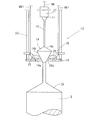
- reference numeral 10 denotes a crystal holding mechanism (hereinafter, crystal holding mechanism) of the single crystal pulling apparatus according to Embodiment 1 of the present invention.
- the crystal holding mechanism 10 is provided continuously with the seed crystal 11 when the single crystal silicon ingot (single crystal ingot) I is grown by pulling up the seed crystal 11 immersed in the melt in the crucible.
- the single crystal silicon ingot I is held by holding 14 using two holding members 15.
- the single crystal pulling apparatus adopts the Czochralski method, and pulls up the single crystal silicon ingot I having a diameter of the straight body portion of 450 mm.
- the single crystal pulling apparatus includes a hollow cylindrical main chamber and a pull chamber that is connected to the main chamber and has a smaller diameter than the main chamber.
- a crucible In the center of the main chamber, a crucible is fixed on a pedestal that can be rotated and lifted.
- a heater is disposed on the outer periphery of the crucible.
- a wire pulling mechanism that feeds the wire W from the drum and winds it up to the drum is provided.
- a seed chuck 27 is provided at the tip of the suspended wire W, and the upper part of the seed crystal 11 is detachably fixed to the lower end of the seed chuck 27.
- an up-and-down rotation mechanism of the crystal holding mechanism 10 is housed in the upper portion of the internal space of the pull chamber. By this up-and-down rotation mechanism, the crystal holding mechanism 10 moves up and down and rotates in a predetermined direction at a predetermined speed.
- the crystal holding mechanism 10 has a cylindrical frame 23 through which an ingot pulling wire W is inserted through an inner space, and the single crystal silicon ingot I is moved up and down and rotated.
- a donut-shaped lifting plate 18 having an inner space 18 a is provided at the lower end of the frame 23.
- a pair of gripping members 15 for gripping the engaging portion 14 are provided on the upper surface of the elevating plate 18 at two opposite locations in the circumferential direction so as to be rotatable about a short horizontal shaft 25. It has been.
- the gripping claw portions 28 that are arranged to face each other are integrally formed at the distal ends of these gripping members 15.
- each operation wire W1 is connected to the base portion of the corresponding gripping member 15.
- the two operation wires W1 of the claw operation mechanism are moved up and down as necessary, and the pair of gripping claw portions 28 are first closed. These gripping claws 28 do not contact the thin neck portion 13 even in the closed state. Thereafter, the wire W drawn out from the drum of the wire pulling mechanism is gradually wound at a predetermined speed while rotating, so that the seed chuck 27, the seed crystal 11 and the neck portion 13 are not sequentially placed in the space inside the gripping claw portion 28. Pass by contact. Thereafter, these gripping claws 28 come into contact with the enlarged diameter portion 14a at the upper end portion of the engaging portion 14 rising in the inner space, and at that time, along the smooth outer surface of the enlarged diameter portion 14a. Turn around the horizontal axis in the opening direction.
- the gripping claws 28 rotate in the closing direction around the horizontal axis due to their own weights. Closed. Thereafter, when the entire engaging portion 14 is pulled up above the gripping claw portion 28, the lifting plate 18 is lifted through the frame 23 by the lifting and lowering rotation mechanism of the crystal holding mechanism 10, whereby the pair of gripping claw portions 28. Thus, the gripping position of the reduced diameter portion 14b is gripped. Thereafter, the single crystal silicon ingot I is pulled up at a low speed while rotating at a predetermined speed in a predetermined speed direction by an elevating and rotating mechanism while the engaging portion 14 is mechanically held by these gripping members 15.
- These gripping claws 28 have a Y-shaped tip 28a in plan view.
- wire ropes (linear springs) 29 are wound several times in the vertical direction, and among these gripping claws 28, an arcuate tip that becomes a contact surface with the reduced diameter portion 14b A coil-like support 30 covering the entire surface is provided (FIGS. 1 and 3).
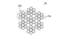
- the wire rope 29 is formed by twisting seven strands 29a made of tungsten to form one lasso 29b, and twisting seven strands 29b (FIG. 4). Each strand 29a has a diameter of 0.16 mm, and the wire rope 29 has a diameter of 2.5 mm.
- the shape of the gripping claw portion 28 may be U-shaped or C-shaped in plan view.
- the wire W at the center is fed from the drum by the wire pulling mechanism, and the lower end of the seed crystal 11 is immersed in the melt in the crucible. This is dissolved, and the seed crystal 11 is left as it is for a predetermined period of time so as to be adapted to the melt. Thereafter, the wire W is rotated in a predetermined direction at a predetermined speed via the lifting / lowering rotation mechanism and the wire pulling mechanism, and the crucible is rotated in the predetermined direction at a predetermined speed.
- the wire W is gradually pulled up by the wire pulling mechanism to form a neck portion 13 that makes the single crystal silicon ingot I dislocation-free at the lower end of the seed crystal 11, and the pulling is continued thereafter, so that the single crystal silicon
- the shoulder portion 35 and the straight body portion of the ingot I are sequentially grown.
- the pulling speed of the wire W by the wire pulling mechanism is adjusted, and a bead-shaped engagement portion composed of the enlarged diameter portion 14 a and the reduced diameter portion 14 b. Grow one. Note that the portion of the neck portion 13 between the engaging portion 14 and the single crystal silicon ingot I does not break the seed crystal 11 and the engaging portion 14 even if the single crystal silicon ingot I is increased in weight.
- the diameter is larger than the portion of the neck portion 13 therebetween.
- the wire W is further wound by the wire pulling mechanism, so that the seed chuck 27, the seed crystal 11 and the neck portion 13 pass through the inner space 18a of the elevating plate 18 and the inner space of the gripping claw portion 28 in this order without contact.
- the gripping claw portions 28 in the closed state then contact the enlarged diameter portion 14a at the upper end portion of the engaging portion 14 that rises in the inner space, and at that time, the enlarged diameter portion 14a gradually increases in diameter. It rotates in the opening direction around the horizontal axis along the outer surface. After that, when the gripping claw portions 28 pass through the enlarged diameter portion 14a, the gripping claw portions 28 rotate in the closing direction around the horizontal axis by the weight of each gripping claw portion 28. Closed.
- the lifting plate 18 is lifted through the frame 23 by the lifting and lowering rotation mechanism of the crystal holding mechanism 10, whereby the pair of gripping claw portions 28.
- the gripping position of the reduced diameter portion 14b is gripped.
- the wire W is wound around the drum at a predetermined speed by the wire pulling mechanism, and the operation wire W1 is operated by the lifting / lowering mechanism so that the single crystal silicon ingot I is pulled up at the same speed, thereby moving the frame 23 at the predetermined speed.
- the single crystal silicon ingot I is grown while being raised and rotated in a predetermined direction at a predetermined rotation speed.
- the reduced diameter portion 14 b of the engaging portion 14 is supported by the two gripping members 15 via the pair of support bodies 30 composed of a plurality of wire ropes 29.
- the support 30 is deformed (elastically deformed) by the load of the single crystal silicon ingot I so as to crush the coil-shaped support 30 from the radial direction in the elastic deformation region of the wire rope 29.
- This deformation increases as the growth of the single crystal silicon ingot I progresses and becomes heavier.
- the contact area of the gripping claw portion 28 with the reduced diameter portion 14b is increased, and the stress per unit area acting on the contact portion with the gripping claw portion 28 is increased. And the breakage and dislocation of the single crystal silicon ingot I from the grip portion of the engaging portion 14 can be prevented.
- the support 30 does not plastically deform as in the conventional crystal holding mechanism, and is composed of a wire rope 29 whose shape can be freely restored in the elastic deformation region. Therefore, after the growth of the single crystal silicon ingot I, another single crystal silicon ingot I is grown sequentially, or the single crystal silicon ingot I is regrown due to the dislocation of the single crystal silicon ingot I during the growth. Even when working, the support 30 can be reused any number of times without replacing it with a new one. As a result, the maintenance cost of the crystal holding mechanism 10 can be reduced.
- the support body 30 is comprised by the wire rope 29, the elasticity of the support body 30 can be obtained by changing the diameter of each strand 29a which comprises the wire rope 29, and changing the twisting method of the strand 29a.
- the power can be changed arbitrarily.
- the support body 30 is matched with the unevenness of the engaging portion 14 of the single crystal silicon ingot I to constitute each wire rope 29.
- the support 30 can be finely deformed by moving (sliding) the strands 29b and the strands 29a (FIG. 5). Thereby, the contact area of the support body 30 and the engaging part 14 can be enlarged further.
- the contact ratio between the reduced diameter portion 14b and the support 30 in the circumferential direction of the reduced diameter portion 14b is also larger (for example, 80 to 90%) than the conventional product (for example, 40 to 60%). It is possible to suppress the local stress concentration at.
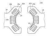
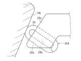
- the crystal holding mechanism 10A of the single crystal pulling apparatus according to the second embodiment of the present invention is characterized by the tip portions 28a of these gripping claws 28 having a substantially Y shape in plan view. Each of these is formed so as to be gradually thinner toward the front, and a part of the support 30A is embedded in the distal end portion 28a of the gripping claw portion 28. Specifically, a total of three pairs of long holes 28b spaced in parallel in the inner and outer directions are formed in these end portions and intermediate portions in the width direction among the tapered tip end portions 28a of the gripping claw portions 28, respectively.
- the winding core portion 28c of the wire rope 29 is integrally formed of the same material as the gripping claw portions 28 between the corresponding long holes 28b.
- the support body 30A is formed in a coil shape by winding the wire rope 29 around each winding core portion 28c many times in a vertically long elliptical shape.
- the upper end portion of each winding of the wire rope 29 protrudes from the upper surface of the gripping claw portion 28, and the lower end portion of each winding of the wire rope 29 protrudes from the lower surface of the gripping claw portion 28.
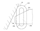
- the reduced diameter portion 14b of the engagement portion 14 is brought into contact with the upper end portion protruding upward of the support 30A, and the load of the single crystal silicon ingot I is applied, whereby the reduced diameter portion 14b.
- the support body 30A is elastically deformed so as to squeeze the coil in the radial direction so as to follow the outer surface shape. Thereby, the local stress concentration in the contact part can be further suppressed.
- the wire rope 29 is wound so that the support 30A protrudes from the upper surface of the gripping claw 28, so that the elastic deformation (cushion) action due to the deformation of the coil shape is also achieved. can get.
- the upper end portions of the support 30A are bent by bending the distal end portions 28a of the gripping claw portions 28 obliquely downward according to the inclination angle of the reduced diameter portion 14b of the engaging portion 14. May be brought into contact with the outer peripheral surface of the reduced diameter portion 14b at a substantially right angle to increase the thickness of the gripping claw portions 28.
- Other configurations, operations, and effects are the same as those in the first embodiment, and thus description thereof is omitted.
- the crystal holding mechanism of the single crystal pulling apparatus according to Embodiment 3 of the present invention will be described.
- the feature of the crystal holding mechanism 10B of the single crystal pulling apparatus according to the third embodiment of the present invention is that the width is gradually narrowed toward the top at the upper ends of the tips of these gripping claws 28.
- the support 30B is formed by winding a taper process and a tungsten linear spring 32 having a diameter of 3 mm many times in a circular shape, and the lower half of the support 30B is formed at the tips of these gripping claws 28. This is a point embedded in the upper surface of the portion 28a over the entire length of the support 30B.
- the gripping claw portions 28 have a circular arc-shaped tip portion 28a in plan view, and the upper surface of the inner edge portion thereof has a substantially arc-shaped cross section in plan view and a cross section perpendicular to the length direction.
- a semicircular fitting groove 28d is formed.
- linear springs 32 wound in a coil shape are fitted in a compressed state.
- These linear springs 32 are firmly fixed to the corresponding fitting grooves 28d using a spring force extending in the coil length direction.
- the coil composed of the linear spring 32 can be easily attached and detached.
- Other configurations, operations, and effects are substantially the same as those of the second embodiment, and thus description thereof is omitted.
- the present invention is characterized by the structure of the distal end portion of the gripping claw portion, and has other configurations excluding the gripping claw portion (opening / closing mechanism of the gripping claw portion or single crystal).
- the clamping mechanism of the engaging portion of the ingot, the lifting mechanism of the crystal holding mechanism, the rotating mechanism, and the like are not limited.
- the single crystal ingot can be safely grown without causing breakage or dislocation in the single crystal ingot. It can be performed.
Landscapes
- Chemical & Material Sciences (AREA)
- Engineering & Computer Science (AREA)
- Crystallography & Structural Chemistry (AREA)
- Materials Engineering (AREA)
- Metallurgy (AREA)
- Organic Chemistry (AREA)
- Crystals, And After-Treatments Of Crystals (AREA)
Abstract
Description
ところで、種結晶には、融液への浸漬時の熱衝撃により転位が発生する。この転位を除去するため、ダッシュ・ネック法が採用されている。ダッシュ・ネック法では、浸漬後の種結晶の直径を細く絞って、直径3mm程度のネック部を種結晶に連続して形成し、このネック部の表面に転位を逃がす。こうしてインゴットを無転位化させた後、種結晶の引き上げ速度を適宜低下させ、インゴットの肩部および直胴部を順次引き上げている。
近年、デバイスの生産効率および歩留りを高めるため、単結晶シリコンインゴットの大径化および長大化が図られている。その結果、インゴットの重量が増大し、従来のダッシュ・ネック法のみでの単結晶インゴット引上げではネック部が破断し、安全なインゴットの育成ができないおそれがあった。
また、単結晶インゴットを育成する際、融液温度の変動や直径制御の精度ばらつきなどに起因し、インゴット外周面の形状を目標形状に完全に一致させることは不可能である。そのため、形成した係合部の外周面には、形状が異なる環状の凹凸が存在する。これにより、把持部材と係合部との接触は点接触または接触幅が短い線接触となってしまい、インゴットに対する単位面積当たりの応力が集中し、係合部の把持箇所でのインゴットの破断および転位が発生していた。単結晶インゴット育成中にインゴットが完全に破断した場合には、インゴット落下という大事故を招く恐れがあった。
しかも、支持体は、塑性変形するものではなく、弾性変形領域内での形状復元が自在な線状ばねから構成されている。そのため、単結晶インゴットの成長後、別の単結晶インゴットを順次成長させる場合や、成長途中での単結晶インゴットの有転位化を原因とした単結晶インゴットの再成長作業を行う場合にも、支持体を新品に交換することなく、複数回にわたって再使用することができる。その結果、結晶保持機構のメンテナンスコストを低減化することができる。
しかも、支持体は、塑性変形するものではなく、弾性変形領域内では形状の復元が自在な線状ばねから構成されている。そのため、単結晶インゴットの成長後、別の単結晶インゴットを順次成長させる場合や、成長途中での単結晶インゴットの有転位化を原因とした単結晶インゴットの再成長作業を行う場合にも、支持体を新しいものに交換することなく、何度でも再使用することができる。その結果、結晶保持機構のメンテナンスコストを低減化することができる。
単結晶引上げ装置としては、各種のチョクラルスキー方式の単結晶引上げ装置を採用することができる。例えば、高磁界印加状態で単結晶インゴットを引き上げるMCZ方式などでもよい。
ここでいう「ネック部と単結晶インゴットの上部との間」とは、種結晶の直下のネック部を基準として、このネック部から単結晶インゴットの肩部までの範囲、または、ネック部から直胴部の上部までの範囲をいう。
係合部とは、種結晶の引き上げ速度を調整することで得られる単結晶インゴットの上方に配置されたそろばんの珠形状の膨出部分である。具体的に係合部とは、ネック部より大径で、かつ上底の面積より下底の面積が大きく、下方に向かって徐々に拡径する円錐台形状の拡径部と、この拡径部に一体的に連続し、かつ下底の面積より上底の面積が大きく、下方に向かって徐々に縮径する逆円錐台形状の縮径部とから構成されている。また、ネック部のうち、係合部と単結晶インゴットとの間の部分は、単結晶インゴットが大重量化しても破断しないように、ネック部の種結晶と係合部との間の部分より大径となっている。
線状ばねの素材としては、例えばばね鋼(SUP)、硬鋼線(SWC)、ステンレス線(SUS)、ピアノ線(SWP)などが挙げられる。
線状ばねとしては、コイルばねの他、円弧形状やリング形状などの各種形状の線加工ばねを採用することができる。
支持体の外観形状としては、例えば螺旋形状、円形状、円弧形状などを採用することができる。支持体の使用数は、1つでも2つ以上でもよい。例えば、多数本のリング形状の線状ばねを、その軸線を一致させて所定ピッチで並列したものでもよい。
把持部材の使用数は、2本、3本またはそれ以上である。把持部材は、その先端部を係合部の縮径部に引っ掛けた状態で単結晶インゴットを引き上げるため、単結晶インゴットのほとんどの荷重が作用する箇所は、縮径部のうち、把持部材との接触部分である。
ワイヤロープの撚り合わせ方法は任意である。例えば、7本線7本撚りや、12本線6本撚りなど、子縄を構成する素線の本数や子縄の本数は任意に選定すればよく、ロープの束ね方も、フィラー形、ウォーリントン形、シール形、ナフレックス形、ヘルクレス形など公知のものを採用することができる。また、ワイヤロープの直径は、細すぎる場合に断線あるいは弾性変形力が十分でなく、直径が太すぎる場合には把持部材への取り付けが困難となるため、1mm~10mm程度のものを採用することが望ましい。
把持部材に形成される長孔は、1対でも2対または3対以上でもよい。
図2において、10はこの発明の実施例1に係る単結晶引上げ装置の結晶保持機構(以下、結晶保持機構)を示している。この結晶保持機構10は、るつぼ内の融液に浸漬した種結晶11を引き上げて単結晶シリコンインゴット(単結晶インゴット)Iを成長させる際、種結晶11に連続して設けられて単結晶シリコンインゴットIを無転位化するネック部13から単結晶シリコンインゴットIの上部までの間に形成され、かつ拡径部14aとこの拡径部14aに連続する縮径部14bとから構成された係合部14を、2つの把持部材15を用いて把持することで、単結晶シリコンインゴットIを保持するものである。
単結晶引上げ装置はチョクラルスキー方式を採用し、直胴部の直径が450mmの単結晶シリコンインゴットIを引き上げる。
単結晶引上げ装置は、中空円筒形状のメインチャンバと、メインチャンバ上に連設され、かつメインチャンバより小径なプルチャンバを備えている。メインチャンバ内の中心部には、るつぼが、回転および昇降が可能なペディスタルの上に固定されている。るつぼの外周にはヒータが配置されている。
また、プルチャンバの内部空間の上部には、結晶保持機構10の昇降回転機構が収納され、この昇降回転機構によって、結晶保持機構10は昇降するとともに所定方向へ所定速度で回転する。
図2に示すように、実施例1の単結晶引上げ装置によるインゴット成長では、まずワイヤ引上げ機構によりドラムから中央部のワイヤWを繰出し、種結晶11の下端部をるつぼ内の融液に浸漬してこれを溶解し、そのまま所定時間だけ種結晶11を放置して融液に馴染ませる。その後、昇降回転機構およびワイヤ引上げ機構を介してワイヤWを所定速度で所定方向へ回転させるとともに、るつぼを所定方向へ所定速度で回転させる。
次に、ワイヤ引上げ機構によりワイヤWを徐々に引き上げて、種結晶11の下端に単結晶シリコンインゴットIを無転位化させるネック部13を形成し、その後も引き上げを継続することで、単結晶シリコンインゴットIの肩部35、直胴部を順次成長させる。ここで、ネック部13から肩部35が成長されるまでの間に、ワイヤ引上げ機構によるワイヤWの引き上げ速度を調整し、拡径部14aと縮径部14bとからなる数珠玉形状の係合部14を1つ育成する。なお、ネック部13のうち、係合部14と単結晶シリコンインゴットIとの間の部分は、単結晶シリコンインゴットIが大重量化しても破断しないように、種結晶11と係合部14の間のネック部13の部分より大径となっている。
図6および図7に示すように、この発明の実施例2の単結晶引上げ装置の結晶保持機構10Aの特徴は、平面視して略Y字形状のこれらの把持爪部28の先端部28aを、それぞれ先方へ向かって徐々に薄肉に形成するとともに、これらの把持爪部28の先端部28aに、支持体30Aの一部を埋設した点である。
具体的には、先細りのこれらの把持爪部28の先端部28aのうち、幅方向のこれらの端部分および中間部分に、内外方向へ平行に離間した合計3対の長孔28bをそれぞれ形成するとともに、各対応する長孔28b間にワイヤロープ29の巻き芯部28cを、これらの把持爪部28と同一素材で一体形成する。その後、各巻き芯部28cにワイヤロープ29を垂直方向へ長い楕円形状に何回も巻き掛けることで、支持体30Aをコイル形状にしたものである。このとき、ワイヤロープ29の各巻きの上端部が把持爪部28の上面から突出し、ワイヤロープ29の各巻きの下端部が把持爪部28の下面から突出している。
また、図8に示すように、これらの把持爪部28の先端部28aを、係合部14の縮径部14bの傾斜角度に合わせて斜め下方へ屈曲させることで、支持体30Aの上端部を、縮径部14bの外周面に略直角に当接させて、これらの把持爪部28の厚さを増大させてもよい。
その他の構成、作用および効果は、実施例1と同じであるので説明を省略する。
図9および図10に示すように、この発明の実施例3の単結晶引上げ装置の結晶保持機構10Bの特徴は、これらの把持爪部28の先端上部に、先方へ向かって徐々に幅狭となるテーパ加工を施す点と、直径3mmのタングステン製の線状ばね32を、円形に何回も巻き付けて支持体30Bを形成し、支持体30Bの下半分を、これらの把持爪部28の先端部28aの上面に、支持体30Bの全長にわたって埋設した点である。具体的には、これらの把持爪部28の平面視して円弧形状の先端部28aには、その内縁部分の上面に、平面視して円弧形状で、かつ長さ方向に直交する断面が略半円形状の嵌合溝28dがそれぞれ形成されている。これらの嵌合溝28dには、コイル状に巻回した線状ばね32が、それぞれ押し縮められた状態で嵌め込まれている。これらの線状ばね32は、コイル長さ方向へ伸長するばね力を利用し、対応する嵌合溝28dに強固に固定されている。その結果、実施例2と同様の効果に加え、線状ばね32からなるコイルの着脱が簡便となる。
その他の構成、作用および効果は、実施例2と略同じであるため説明を省略する。
11 種結晶、
13 ネック部、
14 係合部、
14a 拡径部、
14b 縮径部、
15 把持部材、
28b 長孔、
28c 巻き芯部、
29 ワイヤロープ(線状ばね)、
29a 素線、
29b 子縄、
30,30A,30B 支持体、
32 線状ばね、
I 単結晶シリコンインゴット(単結晶インゴット)。
Claims (4)
- るつぼ内の融液に浸漬した種結晶を引き上げて単結晶インゴットを成長させる際、前記種結晶に連続したネック部から前記単結晶インゴットの上部までの間に形成され、かつ拡径部と該拡径部に連続する縮径部とから構成された係合部を、把持部材を用いて把持することで、前記単結晶インゴットを保持する単結晶引上げ装置の結晶保持機構において、
前記把持部材に、前記係合部を弾性的に支持する線状ばねからなる支持体を設けた単結晶引上げ装置の結晶保持機構。 - 前記線状ばねは、複数本の素線を撚り合わせて子縄を形成し、さらに複数本の該子縄を撚り合わせたワイヤロープで構成された請求項1に記載の単結晶引上げ装置の結晶保持機構。
- 前記把持部材には、上下面を貫通して対配置した長孔を離間して形成するとともに、この対配置した長孔間に形成された巻き芯部に、前記ワイヤロープを垂直方向へ長い楕円形状で、かつ上端部が前記巻き芯部の上面から突出するように複数回巻き掛けることで、前記支持体をコイル形状にした請求項2に記載の単結晶引上げ装置の結晶保持機構。
- るつぼ内の融液に浸漬した種結晶を引き上げて単結晶インゴットを成長させる際、結晶保持機構により前記単結晶インゴットを保持しながら、該単結晶インゴットを成長させる単結晶インゴット製造方法において、
前記種結晶に連続したネック部から前記単結晶インゴットの上部までの間に、拡径部と該拡径部に連続する縮径部とから構成される係合部を形成し、
前記結晶保持機構は、前記係合部を弾性的に支持する線状ばねからなる支持体が設けられて前記係合部を把持する把持部材を有し、
前記係合部の形成後、前記把持部材により前記係合部を把持することで、該係合部を前記支持体により弾性的に支持し、この状態で前記単結晶インゴットの成長を行う単結晶インゴット製造方法。
Priority Applications (3)
| Application Number | Priority Date | Filing Date | Title |
|---|---|---|---|
| US13/985,709 US9593433B2 (en) | 2011-04-06 | 2012-04-04 | Crystal holding mechanism of single crystal pulling device and method for producing single crystal ingot |
| DE112012001596.7T DE112012001596B4 (de) | 2011-04-06 | 2012-04-04 | Kristall-Haltemechanismus für Einkristall-Ziehvorrichtung und Verfahren zur Herstellung von Einkristall-Rohlingen |
| JP2013508898A JP5765642B2 (ja) | 2011-04-06 | 2012-04-04 | 単結晶引上げ装置の結晶保持機構および単結晶インゴット製造方法 |
Applications Claiming Priority (2)
| Application Number | Priority Date | Filing Date | Title |
|---|---|---|---|
| JP2011084400 | 2011-04-06 | ||
| JP2011-084400 | 2011-04-06 |
Publications (1)
| Publication Number | Publication Date |
|---|---|
| WO2012137822A1 true WO2012137822A1 (ja) | 2012-10-11 |
Family
ID=46969216
Family Applications (1)
| Application Number | Title | Priority Date | Filing Date |
|---|---|---|---|
| PCT/JP2012/059203 Ceased WO2012137822A1 (ja) | 2011-04-06 | 2012-04-04 | 単結晶引上げ装置の結晶保持機構および単結晶インゴット製造方法 |
Country Status (4)
| Country | Link |
|---|---|
| US (1) | US9593433B2 (ja) |
| JP (1) | JP5765642B2 (ja) |
| DE (1) | DE112012001596B4 (ja) |
| WO (1) | WO2012137822A1 (ja) |
Families Citing this family (4)
| Publication number | Priority date | Publication date | Assignee | Title |
|---|---|---|---|---|
| DE102014213628B3 (de) * | 2014-07-14 | 2015-10-22 | Wacker Chemie Ag | Halterung für Impflingskristalle und Siliciumstäbe sowie Verfahren zur Herstellung eines einkristallinen Siliciumstabes |
| DE102020100331A1 (de) * | 2020-01-09 | 2021-07-15 | Pva Tepla Ag | Kristallunterstützung und Kristallziehanlage mit einer solchen Kristallunterstützung |
| CN114686979B (zh) * | 2022-03-31 | 2023-03-28 | 徐州鑫晶半导体科技有限公司 | 可竖移止晃的提拉机构及其使用方法 |
| CN116180231A (zh) * | 2022-12-30 | 2023-05-30 | 浙江晶盛机电股份有限公司 | 籽晶提升装置及单晶炉 |
Citations (7)
| Publication number | Priority date | Publication date | Assignee | Title |
|---|---|---|---|---|
| JPH1095690A (ja) * | 1996-09-17 | 1998-04-14 | Sumitomo Sitix Corp | 単結晶引き上げ装置 |
| JPH10273383A (ja) * | 1997-03-27 | 1998-10-13 | Super Silicon Kenkyusho:Kk | 単結晶引上装置 |
| JPH10273389A (ja) * | 1997-03-28 | 1998-10-13 | Super Silicon Kenkyusho:Kk | 単結晶引上げ装置 |
| JP2000007490A (ja) * | 1998-06-22 | 2000-01-11 | Shin Etsu Handotai Co Ltd | 単結晶保持装置 |
| JP2000169291A (ja) * | 1998-10-02 | 2000-06-20 | Komatsu Electronic Metals Co Ltd | 単結晶インゴット製造装置 |
| JP2005029434A (ja) * | 2003-07-07 | 2005-02-03 | Toshiba Ceramics Co Ltd | 単結晶の種結晶保持部材 |
| JP2008031036A (ja) * | 2006-07-26 | 2008-02-14 | Crystal Growing Systems Gmbh | 結晶引上げ設備および重い結晶を製作するための方法 |
Family Cites Families (5)
| Publication number | Priority date | Publication date | Assignee | Title |
|---|---|---|---|---|
| TW541365B (en) | 1996-08-30 | 2003-07-11 | Sumitomo Sitix Corp | Single crystal pulling method and single crystal pulling device |
| JP3596226B2 (ja) | 1997-03-17 | 2004-12-02 | 信越半導体株式会社 | 単結晶保持装置 |
| US6042644A (en) | 1997-07-25 | 2000-03-28 | Komatsu Electronic Metals Co., Ltd. | Single crystal pulling method |
| US6315827B1 (en) * | 1998-10-02 | 2001-11-13 | Komatsu Electronics Metals Co., Ltd. | Apparatus for producing single crystal |
| US8691008B2 (en) * | 2009-03-31 | 2014-04-08 | Memc Electronic Materials, Inc. | Systems for weighing a pulled object |
-
2012
- 2012-04-04 DE DE112012001596.7T patent/DE112012001596B4/de active Active
- 2012-04-04 US US13/985,709 patent/US9593433B2/en active Active
- 2012-04-04 WO PCT/JP2012/059203 patent/WO2012137822A1/ja not_active Ceased
- 2012-04-04 JP JP2013508898A patent/JP5765642B2/ja active Active
Patent Citations (7)
| Publication number | Priority date | Publication date | Assignee | Title |
|---|---|---|---|---|
| JPH1095690A (ja) * | 1996-09-17 | 1998-04-14 | Sumitomo Sitix Corp | 単結晶引き上げ装置 |
| JPH10273383A (ja) * | 1997-03-27 | 1998-10-13 | Super Silicon Kenkyusho:Kk | 単結晶引上装置 |
| JPH10273389A (ja) * | 1997-03-28 | 1998-10-13 | Super Silicon Kenkyusho:Kk | 単結晶引上げ装置 |
| JP2000007490A (ja) * | 1998-06-22 | 2000-01-11 | Shin Etsu Handotai Co Ltd | 単結晶保持装置 |
| JP2000169291A (ja) * | 1998-10-02 | 2000-06-20 | Komatsu Electronic Metals Co Ltd | 単結晶インゴット製造装置 |
| JP2005029434A (ja) * | 2003-07-07 | 2005-02-03 | Toshiba Ceramics Co Ltd | 単結晶の種結晶保持部材 |
| JP2008031036A (ja) * | 2006-07-26 | 2008-02-14 | Crystal Growing Systems Gmbh | 結晶引上げ設備および重い結晶を製作するための方法 |
Also Published As
| Publication number | Publication date |
|---|---|
| DE112012001596B4 (de) | 2018-03-08 |
| US9593433B2 (en) | 2017-03-14 |
| JP5765642B2 (ja) | 2015-08-19 |
| DE112012001596T5 (de) | 2014-02-13 |
| JPWO2012137822A1 (ja) | 2014-07-28 |
| US20130319318A1 (en) | 2013-12-05 |
Similar Documents
| Publication | Publication Date | Title |
|---|---|---|
| JP5765642B2 (ja) | 単結晶引上げ装置の結晶保持機構および単結晶インゴット製造方法 | |
| JP2012513950A5 (ja) | ||
| JP2015010008A (ja) | 単結晶製造装置及び単結晶製造方法 | |
| JPWO2001063026A1 (ja) | シリコン単結晶の製造方法 | |
| JPH07172981A (ja) | 半導体単結晶の製造装置および製造方法 | |
| CN110670122A (zh) | 一种直拉单晶用新型籽晶及熔接工艺 | |
| JPH09142989A (ja) | シリコン単結晶育成装置 | |
| US20090293803A1 (en) | Method of growing silicon single crystals | |
| US9476142B2 (en) | Method for manufacturing silicon single crystal | |
| US20090293802A1 (en) | Method of growing silicon single crystals | |
| US6099642A (en) | Apparatus for pulling up single crystals and single crystal clamping device | |
| JP5053426B2 (ja) | シリコン単結晶製造方法 | |
| JP3870650B2 (ja) | 単結晶製造方法及び単結晶製造装置 | |
| JP3750525B2 (ja) | 単結晶の製造方法および引上げ装置 | |
| JPWO2000040786A1 (ja) | 単結晶の製造方法および引上げ装置 | |
| JP2015214460A (ja) | シリコン単結晶の育成方法 | |
| JPH09227282A (ja) | 単結晶引上げ装置 | |
| CN219689933U (zh) | 一种新型直拉硅芯炉 | |
| JP2004043202A (ja) | 単結晶引き上げ用ワイヤーロープ、単結晶引き上げ装置及び単結晶の製造方法 | |
| JP2014058414A (ja) | 評価用シリコン単結晶の製造方法 | |
| JP3721977B2 (ja) | 単結晶引き上げ方法 | |
| JP2011153033A (ja) | シリコン単結晶の製造方法 | |
| JP2009280435A (ja) | シリコン単結晶の育成方法 | |
| JPWO2009104534A1 (ja) | シリコン単結晶 | |
| JPH11292689A (ja) | シリコン単結晶の製造方法および種結晶ならびに種結晶保持具 |
Legal Events
| Date | Code | Title | Description |
|---|---|---|---|
| 121 | Ep: the epo has been informed by wipo that ep was designated in this application |
Ref document number: 12767975 Country of ref document: EP Kind code of ref document: A1 |
|
| ENP | Entry into the national phase |
Ref document number: 2013508898 Country of ref document: JP Kind code of ref document: A |
|
| WWE | Wipo information: entry into national phase |
Ref document number: 13985709 Country of ref document: US |
|
| WWE | Wipo information: entry into national phase |
Ref document number: 112012001596 Country of ref document: DE Ref document number: 1120120015967 Country of ref document: DE |
|
| 122 | Ep: pct application non-entry in european phase |
Ref document number: 12767975 Country of ref document: EP Kind code of ref document: A1 |