WO2012137665A1 - Procédé de fabrication de granulés d'une composition de résine thermoplastique renforcée par des fibres de verre - Google Patents
Procédé de fabrication de granulés d'une composition de résine thermoplastique renforcée par des fibres de verre Download PDFInfo
- Publication number
- WO2012137665A1 WO2012137665A1 PCT/JP2012/058397 JP2012058397W WO2012137665A1 WO 2012137665 A1 WO2012137665 A1 WO 2012137665A1 JP 2012058397 W JP2012058397 W JP 2012058397W WO 2012137665 A1 WO2012137665 A1 WO 2012137665A1
- Authority
- WO
- WIPO (PCT)
- Prior art keywords
- screw
- glass fiber
- thermoplastic resin
- kneading
- resin composition
- Prior art date
Links
Images


Classifications
-
- C—CHEMISTRY; METALLURGY
- C08—ORGANIC MACROMOLECULAR COMPOUNDS; THEIR PREPARATION OR CHEMICAL WORKING-UP; COMPOSITIONS BASED THEREON
- C08J—WORKING-UP; GENERAL PROCESSES OF COMPOUNDING; AFTER-TREATMENT NOT COVERED BY SUBCLASSES C08B, C08C, C08F, C08G or C08H
- C08J3/00—Processes of treating or compounding macromolecular substances
- C08J3/20—Compounding polymers with additives, e.g. colouring
- C08J3/203—Solid polymers with solid and/or liquid additives
-
- B—PERFORMING OPERATIONS; TRANSPORTING
- B29—WORKING OF PLASTICS; WORKING OF SUBSTANCES IN A PLASTIC STATE IN GENERAL
- B29B—PREPARATION OR PRETREATMENT OF THE MATERIAL TO BE SHAPED; MAKING GRANULES OR PREFORMS; RECOVERY OF PLASTICS OR OTHER CONSTITUENTS OF WASTE MATERIAL CONTAINING PLASTICS
- B29B7/00—Mixing; Kneading
- B29B7/30—Mixing; Kneading continuous, with mechanical mixing or kneading devices
- B29B7/34—Mixing; Kneading continuous, with mechanical mixing or kneading devices with movable mixing or kneading devices
- B29B7/38—Mixing; Kneading continuous, with mechanical mixing or kneading devices with movable mixing or kneading devices rotary
- B29B7/46—Mixing; Kneading continuous, with mechanical mixing or kneading devices with movable mixing or kneading devices rotary with more than one shaft
- B29B7/48—Mixing; Kneading continuous, with mechanical mixing or kneading devices with movable mixing or kneading devices rotary with more than one shaft with intermeshing devices, e.g. screws
- B29B7/482—Mixing; Kneading continuous, with mechanical mixing or kneading devices with movable mixing or kneading devices rotary with more than one shaft with intermeshing devices, e.g. screws provided with screw parts in addition to other mixing parts, e.g. paddles, gears, discs
- B29B7/483—Mixing; Kneading continuous, with mechanical mixing or kneading devices with movable mixing or kneading devices rotary with more than one shaft with intermeshing devices, e.g. screws provided with screw parts in addition to other mixing parts, e.g. paddles, gears, discs the other mixing parts being discs perpendicular to the screw axis
-
- B—PERFORMING OPERATIONS; TRANSPORTING
- B29—WORKING OF PLASTICS; WORKING OF SUBSTANCES IN A PLASTIC STATE IN GENERAL
- B29B—PREPARATION OR PRETREATMENT OF THE MATERIAL TO BE SHAPED; MAKING GRANULES OR PREFORMS; RECOVERY OF PLASTICS OR OTHER CONSTITUENTS OF WASTE MATERIAL CONTAINING PLASTICS
- B29B7/00—Mixing; Kneading
- B29B7/80—Component parts, details or accessories; Auxiliary operations
- B29B7/88—Adding charges, i.e. additives
- B29B7/90—Fillers or reinforcements, e.g. fibres
-
- B—PERFORMING OPERATIONS; TRANSPORTING
- B29—WORKING OF PLASTICS; WORKING OF SUBSTANCES IN A PLASTIC STATE IN GENERAL
- B29C—SHAPING OR JOINING OF PLASTICS; SHAPING OF MATERIAL IN A PLASTIC STATE, NOT OTHERWISE PROVIDED FOR; AFTER-TREATMENT OF THE SHAPED PRODUCTS, e.g. REPAIRING
- B29C48/00—Extrusion moulding, i.e. expressing the moulding material through a die or nozzle which imparts the desired form; Apparatus therefor
- B29C48/03—Extrusion moulding, i.e. expressing the moulding material through a die or nozzle which imparts the desired form; Apparatus therefor characterised by the shape of the extruded material at extrusion
- B29C48/04—Particle-shaped
-
- B—PERFORMING OPERATIONS; TRANSPORTING
- B29—WORKING OF PLASTICS; WORKING OF SUBSTANCES IN A PLASTIC STATE IN GENERAL
- B29C—SHAPING OR JOINING OF PLASTICS; SHAPING OF MATERIAL IN A PLASTIC STATE, NOT OTHERWISE PROVIDED FOR; AFTER-TREATMENT OF THE SHAPED PRODUCTS, e.g. REPAIRING
- B29C48/00—Extrusion moulding, i.e. expressing the moulding material through a die or nozzle which imparts the desired form; Apparatus therefor
- B29C48/25—Component parts, details or accessories; Auxiliary operations
- B29C48/285—Feeding the extrusion material to the extruder
- B29C48/288—Feeding the extrusion material to the extruder in solid form, e.g. powder or granules
- B29C48/2886—Feeding the extrusion material to the extruder in solid form, e.g. powder or granules of fibrous, filamentary or filling materials, e.g. thin fibrous reinforcements or fillers
-
- B—PERFORMING OPERATIONS; TRANSPORTING
- B29—WORKING OF PLASTICS; WORKING OF SUBSTANCES IN A PLASTIC STATE IN GENERAL
- B29C—SHAPING OR JOINING OF PLASTICS; SHAPING OF MATERIAL IN A PLASTIC STATE, NOT OTHERWISE PROVIDED FOR; AFTER-TREATMENT OF THE SHAPED PRODUCTS, e.g. REPAIRING
- B29C48/00—Extrusion moulding, i.e. expressing the moulding material through a die or nozzle which imparts the desired form; Apparatus therefor
- B29C48/25—Component parts, details or accessories; Auxiliary operations
- B29C48/36—Means for plasticising or homogenising the moulding material or forcing it through the nozzle or die
- B29C48/395—Means for plasticising or homogenising the moulding material or forcing it through the nozzle or die using screws surrounded by a cooperating barrel, e.g. single screw extruders
- B29C48/40—Means for plasticising or homogenising the moulding material or forcing it through the nozzle or die using screws surrounded by a cooperating barrel, e.g. single screw extruders using two or more parallel screws or at least two parallel non-intermeshing screws, e.g. twin screw extruders
- B29C48/405—Intermeshing co-rotating screws
-
- B—PERFORMING OPERATIONS; TRANSPORTING
- B29—WORKING OF PLASTICS; WORKING OF SUBSTANCES IN A PLASTIC STATE IN GENERAL
- B29C—SHAPING OR JOINING OF PLASTICS; SHAPING OF MATERIAL IN A PLASTIC STATE, NOT OTHERWISE PROVIDED FOR; AFTER-TREATMENT OF THE SHAPED PRODUCTS, e.g. REPAIRING
- B29C48/00—Extrusion moulding, i.e. expressing the moulding material through a die or nozzle which imparts the desired form; Apparatus therefor
- B29C48/25—Component parts, details or accessories; Auxiliary operations
- B29C48/36—Means for plasticising or homogenising the moulding material or forcing it through the nozzle or die
- B29C48/50—Details of extruders
- B29C48/505—Screws
- B29C48/54—Screws with additional forward-feeding elements
-
- B—PERFORMING OPERATIONS; TRANSPORTING
- B29—WORKING OF PLASTICS; WORKING OF SUBSTANCES IN A PLASTIC STATE IN GENERAL
- B29C—SHAPING OR JOINING OF PLASTICS; SHAPING OF MATERIAL IN A PLASTIC STATE, NOT OTHERWISE PROVIDED FOR; AFTER-TREATMENT OF THE SHAPED PRODUCTS, e.g. REPAIRING
- B29C48/00—Extrusion moulding, i.e. expressing the moulding material through a die or nozzle which imparts the desired form; Apparatus therefor
- B29C48/25—Component parts, details or accessories; Auxiliary operations
- B29C48/36—Means for plasticising or homogenising the moulding material or forcing it through the nozzle or die
- B29C48/50—Details of extruders
- B29C48/505—Screws
- B29C48/55—Screws having reverse-feeding elements
-
- B—PERFORMING OPERATIONS; TRANSPORTING
- B29—WORKING OF PLASTICS; WORKING OF SUBSTANCES IN A PLASTIC STATE IN GENERAL
- B29C—SHAPING OR JOINING OF PLASTICS; SHAPING OF MATERIAL IN A PLASTIC STATE, NOT OTHERWISE PROVIDED FOR; AFTER-TREATMENT OF THE SHAPED PRODUCTS, e.g. REPAIRING
- B29C48/00—Extrusion moulding, i.e. expressing the moulding material through a die or nozzle which imparts the desired form; Apparatus therefor
- B29C48/25—Component parts, details or accessories; Auxiliary operations
- B29C48/36—Means for plasticising or homogenising the moulding material or forcing it through the nozzle or die
- B29C48/50—Details of extruders
- B29C48/505—Screws
- B29C48/56—Screws having grooves or cavities other than the thread or the channel
-
- B—PERFORMING OPERATIONS; TRANSPORTING
- B29—WORKING OF PLASTICS; WORKING OF SUBSTANCES IN A PLASTIC STATE IN GENERAL
- B29C—SHAPING OR JOINING OF PLASTICS; SHAPING OF MATERIAL IN A PLASTIC STATE, NOT OTHERWISE PROVIDED FOR; AFTER-TREATMENT OF THE SHAPED PRODUCTS, e.g. REPAIRING
- B29C48/00—Extrusion moulding, i.e. expressing the moulding material through a die or nozzle which imparts the desired form; Apparatus therefor
- B29C48/25—Component parts, details or accessories; Auxiliary operations
- B29C48/36—Means for plasticising or homogenising the moulding material or forcing it through the nozzle or die
- B29C48/50—Details of extruders
- B29C48/505—Screws
- B29C48/57—Screws provided with kneading disc-like elements, e.g. with oval-shaped elements
-
- B—PERFORMING OPERATIONS; TRANSPORTING
- B29—WORKING OF PLASTICS; WORKING OF SUBSTANCES IN A PLASTIC STATE IN GENERAL
- B29C—SHAPING OR JOINING OF PLASTICS; SHAPING OF MATERIAL IN A PLASTIC STATE, NOT OTHERWISE PROVIDED FOR; AFTER-TREATMENT OF THE SHAPED PRODUCTS, e.g. REPAIRING
- B29C48/00—Extrusion moulding, i.e. expressing the moulding material through a die or nozzle which imparts the desired form; Apparatus therefor
- B29C48/25—Component parts, details or accessories; Auxiliary operations
- B29C48/36—Means for plasticising or homogenising the moulding material or forcing it through the nozzle or die
- B29C48/50—Details of extruders
- B29C48/505—Screws
- B29C48/585—Screws provided with gears interacting with the flow
-
- B—PERFORMING OPERATIONS; TRANSPORTING
- B29—WORKING OF PLASTICS; WORKING OF SUBSTANCES IN A PLASTIC STATE IN GENERAL
- B29C—SHAPING OR JOINING OF PLASTICS; SHAPING OF MATERIAL IN A PLASTIC STATE, NOT OTHERWISE PROVIDED FOR; AFTER-TREATMENT OF THE SHAPED PRODUCTS, e.g. REPAIRING
- B29C48/00—Extrusion moulding, i.e. expressing the moulding material through a die or nozzle which imparts the desired form; Apparatus therefor
- B29C48/25—Component parts, details or accessories; Auxiliary operations
- B29C48/78—Thermal treatment of the extrusion moulding material or of preformed parts or layers, e.g. by heating or cooling
- B29C48/793—Thermal treatment of the extrusion moulding material or of preformed parts or layers, e.g. by heating or cooling upstream of the plasticising zone, e.g. heating in the hopper
-
- B—PERFORMING OPERATIONS; TRANSPORTING
- B29—WORKING OF PLASTICS; WORKING OF SUBSTANCES IN A PLASTIC STATE IN GENERAL
- B29B—PREPARATION OR PRETREATMENT OF THE MATERIAL TO BE SHAPED; MAKING GRANULES OR PREFORMS; RECOVERY OF PLASTICS OR OTHER CONSTITUENTS OF WASTE MATERIAL CONTAINING PLASTICS
- B29B9/00—Making granules
- B29B9/12—Making granules characterised by structure or composition
- B29B9/14—Making granules characterised by structure or composition fibre-reinforced
-
- B—PERFORMING OPERATIONS; TRANSPORTING
- B29—WORKING OF PLASTICS; WORKING OF SUBSTANCES IN A PLASTIC STATE IN GENERAL
- B29C—SHAPING OR JOINING OF PLASTICS; SHAPING OF MATERIAL IN A PLASTIC STATE, NOT OTHERWISE PROVIDED FOR; AFTER-TREATMENT OF THE SHAPED PRODUCTS, e.g. REPAIRING
- B29C48/00—Extrusion moulding, i.e. expressing the moulding material through a die or nozzle which imparts the desired form; Apparatus therefor
- B29C48/25—Component parts, details or accessories; Auxiliary operations
- B29C48/285—Feeding the extrusion material to the extruder
- B29C48/297—Feeding the extrusion material to the extruder at several locations, e.g. using several hoppers or using a separate additive feeding
-
- B—PERFORMING OPERATIONS; TRANSPORTING
- B29—WORKING OF PLASTICS; WORKING OF SUBSTANCES IN A PLASTIC STATE IN GENERAL
- B29K—INDEXING SCHEME ASSOCIATED WITH SUBCLASSES B29B, B29C OR B29D, RELATING TO MOULDING MATERIALS OR TO MATERIALS FOR MOULDS, REINFORCEMENTS, FILLERS OR PREFORMED PARTS, e.g. INSERTS
- B29K2105/00—Condition, form or state of moulded material or of the material to be shaped
- B29K2105/06—Condition, form or state of moulded material or of the material to be shaped containing reinforcements, fillers or inserts
- B29K2105/12—Condition, form or state of moulded material or of the material to be shaped containing reinforcements, fillers or inserts of short lengths, e.g. chopped filaments, staple fibres or bristles
-
- C—CHEMISTRY; METALLURGY
- C08—ORGANIC MACROMOLECULAR COMPOUNDS; THEIR PREPARATION OR CHEMICAL WORKING-UP; COMPOSITIONS BASED THEREON
- C08J—WORKING-UP; GENERAL PROCESSES OF COMPOUNDING; AFTER-TREATMENT NOT COVERED BY SUBCLASSES C08B, C08C, C08F, C08G or C08H
- C08J2367/00—Characterised by the use of polyesters obtained by reactions forming a carboxylic ester link in the main chain; Derivatives of such polymers
- C08J2367/02—Polyesters derived from dicarboxylic acids and dihydroxy compounds
Definitions
- the present invention relates to a method for producing glass fiber reinforced thermoplastic resin composition pellets.
- thermoplastic resin composition pellets As a method for producing glass fiber reinforced thermoplastic resin composition pellets by mixing and kneading glass fibers with a thermoplastic resin, first, a thermoplastic resin is supplied to an extruder and the thermoplastic resin is melted. Next, glass fibers are supplied to the molten thermoplastic resin, and the thermoplastic resin and glass fibers are mixed and kneaded in an extruder. Finally, a method of cooling and granulating the mixture is common.
- the extruder generally, a single-screw extruder and a fully meshed twin-screw extruder in the same direction (hereinafter sometimes referred to as a twin-screw extruder) are used. Compared with a single screw extruder, a twin screw extruder has higher productivity and freedom of operation, and therefore, a twin screw extruder is more preferably used for producing glass fiber reinforced thermoplastic resin pellets. .
- the glass fiber used in the production of the glass fiber reinforced thermoplastic resin composition pellets is a monofilament having a diameter of 6 ⁇ m to 20 ⁇ m, which is bundled into about 300 to 3000 pieces and wound on a roving, or the roving has a length of 1 Cut to 4 mm (hereinafter sometimes referred to as chopped strands).
- thermoplastic resin Since chopped glass can be used more easily, in the case of producing glass fiber reinforced thermoplastic resin composition pellets industrially, the thermoplastic resin is supplied to a twin screw extruder, and after the thermoplastic resin is melted, The most common method is to supply chopped glass from the middle of a shaft extruder, mix and knead a molten thermoplastic resin and glass fiber, extrude the mixture, and cool and solidify.
- the productivity of the glass fiber reinforced thermoplastic resin composition pellets using the above twin screw extruder is determined by the plasticizing and mixing and kneading ability of the twin screw extruder.
- the plasticizing ability of the twin screw extruder depends on the screw design, the torque generated by the screw, the groove depth of the screw (the difference between the outer diameter and the valley diameter of the screw), the rotational speed of the screw, and the like.
- Patent Document 1 discloses a twin-screw extruder having a high plasticizing ability and excellent productivity, in which a value obtained by dividing the distance between the centers of two screws by the third power is defined as torque density.
- the mixing and kneading ability of the twin screw extruder depends on the screw design.
- the residence time decreased with the improvement of the plasticizing ability of the twin screw extruder. For this reason, development of a screw design having an efficient mixing and kneading ability in a short time is required.
- studies on techniques for increasing the plasticizing ability and kneading ability of a twin-screw extruder have been conducted.
- a monofilament bundle is used as described above. This is because, in the method of supplying glass fibers to a twin-screw extruder without forming a bundle of monofilaments, the monofilament becomes cottony, loses fluidity, and is difficult to handle.
- the chopped strand is mixed and kneaded in a twin-screw extruder until it is fibrillated and becomes a monofilament. At the same time, the chopped strand is broken by a screw or the like until the monofilament length reaches an average of 200 ⁇ m to 800 ⁇ m.
- the monofilament will not be defibrated, and a part or all of the chopped strand that is in the state of a monofilament aggregate (undefibrated glass fiber bundle) will be resin composition It remains in the product pellet. If some or all of the chopped strands remain in the glass fiber reinforced thermoplastic resin composition pellets, in injection molding, some or all of the chopped strands may be clogged in the gate, making injection molding impossible, or injection molding. Even if it is possible, some or all of the chopped strands are present in the molded product, resulting in poor appearance or reduced function.
- glass fiber reinforced thermoplastic resin compositions used as parts are required to be thin and molded into complex shapes.
- the gate nozzle of a molding machine that performs such precision molding is often 1 mm or less.
- the presence of undefined glass fiber bundles becomes a very serious defect.
- the present invention has been made in order to solve the above-mentioned problems.
- the object of the present invention is to increase the productivity of glass fiber reinforced thermoplastic resin composition pellets as compared with the prior art, and to collect the monofilaments in the manufactured pellets. It is providing the manufacturing method of the glass fiber reinforced thermoplastic resin composition pellet which can make very low the probability that (un-defibrated glass fiber bundle) remains.
- the inventors of the present invention have made extensive studies to solve the above problems.
- the physical quantities obtained by numerical analysis such as average shear stress history, average shear strain history, specific energy, shortest particle outflow time, etc. are all the number N of pellets containing undefined glass fiber bundles (per unit weight). It is found that there is no clear correlation with the number of pellets containing undefined glass fiber bundles) and the smallest value among the time integral values of shear stress applied to each glass fiber bundle, which is derived by the particle tracking method. It was found that the minimum shear stress history value T min is correlated with the number N of pellets including undefined glass fiber bundles.
- the shear stress generated in the twin screw extruder is analyzed, and when the ratio (Q / Ns) between the discharge amount Q and the screw rotation speed Ns is constant, the minimum shear stress history value T min is controlled.
- the present inventors have found that the number N of pellets per unit amount including undefined glass fibers can be controlled. Further, even if the ratio (Q / Ns) is not constant, the number N of pellets per unit amount including undefined glass fibers can be expressed by a specific formula using the T min and (Q / Ns). I found out.
- the present inventors have found that the above-mentioned problems can be solved by having a screw element having a specific shape for a screw for kneading a thermoplastic resin and glass fiber, thereby completing the present invention. More specifically, the present invention provides the following.
- thermoplastic resin pellets using a twin screw extruder provided with screws that rotate and mesh with each other, wherein the thermoplastic resin is supplied to the extruder and heated.
- a kneading step of kneading the plasticized thermoplastic resin with a screw an extrusion step of extruding the glass fiber reinforced thermoplastic resin composition after the kneading step, and the extruded glass fiber reinforced thermoplastic resin composition.
- thermoplastic resin is at least one selected from polybutylene terephthalate resin, liquid crystalline resin, and polyarylene sulfide resin
- the screw includes a single forward feed screw element having a flight part in which an arc-shaped notch satisfying the following inequalities (I) to (III) is formed on the outer periphery.
- thermoplastic resin composition pellets using a biaxial extruder equipped with screws that rotate and mesh with each other, A plasticizing step of supplying a thermoplastic resin to the extruder and heating, kneading and plasticizing; After the plasticizing step, one or more glass fiber bundles are supplied to the extruder, and the defibrated glass fibers and the plasticized thermoplastic resin are screwed together while defibrating the glass fiber bundles.
- a kneading step for kneading After the kneading step, an extrusion step of extruding the glass fiber reinforced thermoplastic resin composition, Pelletizing step of pelletizing the extruded glass fiber reinforced thermoplastic resin composition,
- the viscosity of the thermoplastic resin is 100 Pa ⁇ s or less under the condition of a shear rate of 1000 sec ⁇ 1 ;
- the screw has a glass fiber reinforced heat having one or more progressive screw elements each having a flight portion in which an arc-shaped notch satisfying the following inequalities (I) to (III) is formed on the outer periphery.
- a method for producing a plastic resin composition pellet A method for producing a plastic resin composition pellet.
- the screw has at least one reverse feed screw element having a flight portion having an arc-shaped notch formed on the outer periphery thereof.
- (1) or (2) A method for producing a thermoplastic resin composition pellet.
- the productivity of the glass fiber reinforced thermoplastic resin composition pellets is increased more than before, and the probability that monofilament aggregates (undefined glass fiber bundles) remain in the manufactured pellets is very high.
- the fiber length distribution of the glass fiber can be controlled.
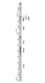
- FIG. 1 is a schematic diagram illustrating an example of a screw configuration of an extruder.
- FIG. 2 is a diagram schematically showing a forward feed single screw element having a flight portion in which an arcuate cutout is formed.
- FIG. 3 is a schematic diagram showing the screw configuration of the extruder used in the examples.
- FIG. 4 is a diagram showing a specific screw pattern used in the example.
- FIG. 5 is a diagram showing a specific screw shape used in the example.
- FIG. 1 is a schematic diagram illustrating an example of a screw configuration of an extruder.
- FIG. 2 is a diagram schematically showing a forward feed single screw element having a flight portion in which an arcuate
- FIG. 8 shows the minimum shear stress history value (Pa ⁇ sec) independent of the Q / Ns of the extruder used in the examples, and the number of pellets in which part or all of the glass fiber bundle is not defibrated (pieces / pellet 10 kg). It is a figure which shows the relationship (correlation line).
- FIG. 9 is a diagram showing the relationship between the number of notches n and the minimum shear stress history value Tmin .
- FIG. 10 is a diagram showing the distribution of shear stress history values for each type of screw element.
- FIG. 11 is a schematic diagram showing a screw configuration of a screw disposed in the extruder used in the examples and comparative examples.
- the manufacturing method of the glass fiber reinforced thermoplastic resin composition pellet of the present invention includes the following steps.
- a plasticizing process in which a thermoplastic resin is supplied to an extruder and heated, kneaded and plasticized. After the plasticization step, one or more glass fiber bundles are supplied to the extruder, and the glass fiber bundles and the plasticized thermoplastic resin are screwed together while the glass fiber bundles are defibrated.
- a pelletizing step of pelletizing the extruded glass fiber reinforced thermoplastic resin composition.
- the production method of the present invention uses a screw having a specific screw element in the kneading step.
- FIG. 1 shows a twin-screw extruder including a cylinder 1, a screw 2 disposed in the cylinder, and a die 3 provided at a downstream end portion of the cylinder 1.
- FIG. 1 also shows the screw configuration of the screw 2.
- the screw 2 includes a supply unit 20, a plasticizing unit 21, a transport unit 22, and a kneading unit 23 in this order from the upstream side. A plasticizing process is performed in the supply unit 20 and the plasticizing unit 21.
- a kneading step is performed in the conveying unit 22 and the kneading unit 23.
- the extrusion process is performed after the kneading section 23.
- a pelletization process is performed after the glass fiber reinforced thermoplastic resin composition is extruded from the die
- the cylinder 1 in which the screw 2 is disposed includes a hopper 10 for supplying a raw material such as a thermoplastic resin to the supply unit 20 and a feed port for supplying auxiliary materials such as a glass fiber bundle to the conveyance unit 22. 11 and a vacuum vent 12 having vacuuming means such as a vacuum pump for performing vacuum deaeration at a predetermined degree of vacuum.
- thermoplastic resin supplied from the hopper 10 is transferred and melted to make a homogeneous melt.
- thermoplastic resin will be described, and then the details of the plasticizing process until the thermoplastic resin supplied from the hopper becomes a homogeneous melt will be described.
- thermoplastic resin refers to a polybutylene terephthalate resin, a liquid crystalline resin, or a polyarylene sulfide resin. Even a resin having a low viscosity tends to exhibit the effects of the present invention.
- the above-mentioned resin having low viscosity tends to cause a problem of undefining the glass fiber bundle. This is because if the viscosity is low, shear stress hardly occurs in the molten state, and the glass fiber bundle in which the monofilaments are converged is difficult to be defibrated.
- the low viscosity resin means that the viscosity of the thermoplastic resin is 100 Pa ⁇ s or less under the condition of a shear rate of 1000 sec ⁇ 1 .
- thermoplastic tree used as a raw material is shaped into a pellet.
- thermoplastic resin composition containing other components may be used into the pellet form.
- the plasticizing process is performed in the supply unit 20 and the plasticizing unit 21 of the screw 2.
- the screw element used in the supply unit 20 include a transport element made of a flight.
- the screw element used for the plasticizing portion 21 generally include a combination of screw elements such as reverse flight, seal ring, forward kneading disk, and reverse kneading disk.
- Supplied part 20 transfers resin pellets.
- the supply unit 20 functions to transfer the resin pellets from the hopper 10 side to the die 3 direction side. In general, preheating by an external heater is performed as a melting preparation stage. Further, since the resin pellet is sandwiched between the rotating screw 2 and the cylinder 1, a frictional force is applied to the resin pellet to generate frictional heat. The resin pellets may start to melt due to the preheating or frictional heat. In some cases, the supply unit 20 needs to adjust the groove depth of the screw 2 and adjust the preheating temperature by a conventionally known method so that the transfer of the resin pellets proceeds smoothly.
- the plasticizing unit 21 applies pressure to the resin pellets transferred from the supply unit 20 to melt the resin pellets.
- the resin pellets are further transferred forward (in the direction from the hopper 10 to the die 3) while melting.
- the kneading step After the plasticizing step, one or more glass fiber bundles are supplied to an extruder and the glass fiber bundle is defibrated and melted in the plasticizing step with the defibrated glass fibers. And knead.
- the kneading step is performed by the conveying unit 22 and the kneading unit 23 of the screw 2.
- a screw element used by the conveyance part 22 the element for conveyance which consists of a forward flight, for example is mentioned.
- screw element used in the kneading part 23 the combination of screw elements, such as a reverse flight, a seal ring, a forward kneading disk, a reverse kneading disk, is common.
- a continuous feed having a flight part in which at least a part of the kneading part 22 of the screw 2 has an arc-shaped notch satisfying the inequalities (I) to (III) formed on the outer periphery.
- a screw element is provided.
- the kneading part 22 includes the screw element and a single reverse feed screw element having a flight part having a notch formed on the outer periphery.
- the glass fiber bundle is a chopped strand in which 300 to 3000 monofilaments are bundled.
- chopped strands in which 1100 pieces or 2200 pieces are bundled are preferably used.
- the diameter of the monofilament is not particularly limited, but is preferably in the range of 6 ⁇ m to 20 ⁇ m, and those having a diameter of 6 ⁇ m, 10 ⁇ m, and 13 ⁇ m are widely distributed in the market.
- a bundle of monofilaments can be continuously fed to the twin screw extruder while roving.
- the chopped strand from which roving is cut is easy to handle in transportation and supply to a twin screw extruder.
- the glass fiber bundle and the molten resin introduced from the feed port 11 are conveyed to the kneading unit 23.
- this conveyance part 22 it is an area
- shear stress is applied to the glass fiber bundle and the molten resin.
- the glass fiber bundle is defibrated and the monofilament and the molten resin are kneaded.
- the glass fiber reinforced thermoplastic resin composition is extruded and how it is pelletized.
- the glass fiber reinforced thermoplastic resin composition extruded into a rod shape from the die 3 can be cut and pelletized.
- the cutting method is not particularly limited, and a conventionally known method can be used.
- the discharge amount in the extrusion process corresponds to the discharge amount Q
- the rotation speed of the screw corresponds to the rotation speed Ns.
- ⁇ Screw element> As a conventional kneading part of a screw, a combination of screw elements such as a reverse flight, a seal ring, a forward kneading disk, and a reverse kneading disk is generally used. However, in the case of high discharge under conditions where Q / Ns is large, some glass fiber bundles are not defibrated and remain undefibrated.
- the present invention is a manufacturing method determined by using, as an index, a shear stress history value received by each glass fiber bundle in an extruder.
- the minimum shear stress history value T min is the minimum value of the shear stress history value each glass fiber bundle is subjected in a twin-screw extruder.
- the following formula (IV) is derived based on the number of pellets including fiber glass fiber bundles.
- the following formula (IV) is also useful in that the amount of pellets containing undefined glass fiber bundles can be studied with one formula even if the Q / Ns condition changes.
- the quantity of the pellet containing an undefined glass fiber bundle can be examined with one numerical formula (IV).
- the size of the twin-screw extruder is changed, it is necessary to derive the formula (IV) again.
- a small twin screw extruder and a large twin screw extruder have different heat transfer amounts from the cylinders and heat energy applied to the molten resin. It is.
- the screw diameter D is uniquely determined. Based on the screw diameter D, the arbitrarily determined length L of the kneading portion 23, the discharge amount Q as the arbitrarily determined molding condition, and the screw rotation speed Ns, the minimum shear stress history value Tmin is derived.
- the minimum shear stress history value T min can be derived using conventionally known three-dimensional flow analysis software in a twin-screw extruder. For example, it can be derived by particle tracking analysis as described in the examples.
- the minimum shear stress history value T min is a time integral value obtained by performing time integration of the shear stress.
- the integration section is a section where the shear stress is applied to the molten resin and the glass fiber bundle, and the extrusion shown in FIG. In the case of a machine, it is a section of the kneading unit 23.
- the method for deriving the minimum shear stress history value Tmin is not particularly limited. A method of deriving using commercially available software, a method of deriving by experiment, and the like can be mentioned.
- the number N of undefibrated pellets may be derived experimentally or using an analysis method or the like.
- the horizontal axis is the minimum shear stress history value T min
- the vertical axis is the number N of undefined pellets.
- Screw diameter D of the screw element vary from d1 to d2, the following equation (V) is established between the discharge amount Q M in the discharge amount Q m and a large extruder in a small extruder and, following equation (VI) is established between the screw rotation speed Ns M at a screw rotation speed Ns m and a large extruder a small extruder.
- ⁇ and ⁇ in the above formulas (V) and (VI) are determined so that the specific energy applied to the molten resin is equal.
- a method for determining ⁇ and ⁇ either a theoretical determination method or an experimental determination method may be used.
- the parameter ⁇ is set so that the specific function, the total shearing amount, the residence time, etc. of the objective function are the same between the small machine and the large machine.
- ⁇ are derived. Assuming the difference in heat transfer between the small machine and the large machine, the parameters ⁇ and ⁇ can be derived so that the specific energy as the objective function matches between the small machine and the large machine.
- the objective function is a specific energy, or a parameter indicating physical properties is adopted, and the parameter ⁇ is statistically set so that the objective function matches between a small machine and a large machine. And a method of calculating ⁇ .
- the viscosity of the thermoplastic resin used as a raw material is high, the value of the minimum shear stress history value Tmin increases, which is advantageous for defibration of the glass fiber bundle, and glass undefibration is unlikely to occur even by a normal method.
- the present invention provides a method that is particularly effective when the viscosity of a thermoplastic resin is low and it is difficult to disentangle a glass fiber bundle by a normal method.
- the discharge rate is increased by a twin screw extruder, the glass undefibrated bundle is obtained when the viscosity of the thermoplastic resin is 100 Pa ⁇ s or less at a shear rate of 1000 sec ⁇ 1 at the processing temperature in the extruder. Is likely to occur.
- the viscosity is expressed as a value at 1000 sec ⁇ 1 ).
- fluidity is required in precision molding, and a resin having a viscosity of 30 to 70 Pa ⁇ s is used.
- the resin composition has a viscosity of 50 to 200 Pa ⁇ s.
- the screw element for defibrating the glass fiber bundle in such a low viscosity region will be described.
- a single screw element having a flight part with a notch formed on the outer periphery is preferable because the minimum shear stress history value T min tends to increase.
- a single screw element itself having a flight part with a notch formed on the outer periphery is known, and is described, for example, in Patent Document (DE4134026A1).
- the number N of undefined pellets can be suppressed to a small value by using a single progressive screw element described below.
- the screw elements having the above-mentioned notches it is possible to use the forward-feeding one because the value of the minimum shear stress history value Tmin is increased, and the glass fiber is used in a shorter time than when other screw elements are used. This is preferable because the bundle can be defibrated.
- This one-step progressive screw element has a flight part in which an arc-shaped notch satisfying the following inequalities (I) to (III) is formed on the outer periphery.
- FIG. 2 is a schematic view of the above-mentioned one-step progressive screw element, where (a) is a sectional view in the axial direction, and (b) is a side view.
- the single progressive screw element 4 has a flight part 40 and an arc-shaped notch 41 formed on the outer periphery of the flight part 40.
- the notch 41 is formed in a direction from the outer periphery of the flight part toward the axis of the screw element. 2 shows a case where the ellipse forms an arc shape, but the ellipse or the center of the circle forming the arc shape exists on the outer periphery of the flight part 40 (in FIG. 2A, the center of the ellipse is present). Indicated by O).
- the notch has an arc shape, and the arc shape is formed by the circle or ellipse, so that there are advantages in manufacturing and an effect of minimizing a decrease in strength of the flight portion due to the notch.
- the said circular arc shape should just be formed by said circle
- the present invention is not limited to one in which the entire cutout is formed by the one circle or ellipse described above. However, it is preferable that substantially the entire arc shape is formed by one circle or ellipse.
- the arc shape is most preferably a circle.
- the range of the radius r is preferably 0.05D ⁇ r ⁇ 0.15D. If r is within the above range, the minimum shear stress history value Tmin tends to increase, which is preferable. A more preferable range of r is 0.06D ⁇ r ⁇ 0.12D.
- the minimum shear stress history value T min tends to increase as the number of notches n increases.
- the mechanical strength of the screw element is lowered when the number of notches n is excessively increased, the number of notches n is adjusted within the range of inequality (II).
- a particularly preferable range of the number of notches n is 10 ⁇ n ⁇ 12, and the most preferable number of notches is 11.
- the lead length Le of the screw element is not more than 0.3 times the screw diameter D of the screw element (Le is not more than 0.3D). If the lead length Le is 0.3D or less, even if the discharge rate Q is very high, undisrupted glass fibers tend not to be contained in the manufactured pellets. It should be noted that the discharge amount Q is very high, for example, when the screw element is provided with an axial length of 2D and a screw diameter D is 47 mm, the screw diameter is 47 mm. This is a twin screw extruder having a diameter D of 69 mm and is 800 kg / h or more. Even in such a high discharge area, problems due to the above-described undefined glass fibers can be suppressed.
- the upper limit of the lead length Le of the screw element used in the present invention is preferably 0.3D or less, but the lower limit is preferably 0.1D or more. Setting it above this lower limit is preferable because the thickness of the flight part is maintained and the strength is maintained.
- the length of a single screw element having a flight part with a notch formed in the outer peripheral surface used for the kneading part 23 is expressed as L / D (L is a screw in the kneading part 23).
- D is the screw diameter
- T min the minimum shear stress history value
- said preferable length changes with kinds of resin.
- polybutylene terephthalate resin it is preferably 2D or more and 3.5D or less.
- each screw element is more effective to combine a reverse screw element of a single screw element having a flight part with a notch formed in the outer peripheral surface and the forward screw element.
- the most effective combination is a combination in which each is alternately arranged.
- the length of each screw element can be adjusted as appropriate.
- a single feed forward screw element having a flight part with a notch formed on the outer periphery, or a combination of a reverse feed screw element and a forward feed screw element includes almost no glass undefibration. It is possible to efficiently produce a glass reinforced resin composition with high productivity.
- Carbon masterbatch glass fiber bundle 3 mm long chopped strand obtained by bundling 2200 monofilaments having a diameter of 13 ⁇ m
- the composition is as follows. PBT is 67.5 mass%, carbon masterbatch is 2.5 mass%, glass fiber bundle is 30 mass% Extrusion conditions are as follows.
- Extruder Same direction full meshing type twin screw extruder TEX44 ⁇ II (manufactured by Nippon Steel) Screw diameter D of screw element is 0.047m Extrusion conditions; Barrel temperature; 220 ° C Screw design; (1) Outline The screw of the extruder can be represented as shown in FIG. 3, and the outline of the screw pattern shown in FIG. 3 is as follows.
- L / D is the ratio (L / D) between the lead length (L) of the kneading part b1 and the screw diameter (D) of the screw element.
- the screw patterns shown in FIG. 4 differ only in the kneading part B of C11.
- the shape of the screw of the kneading part B of C11 is shown in FIG.
- the screw shape of the pattern of FIG. 4 (a) is shown in FIG. 5 (a)
- the screw shape of the pattern of FIG. 4 (b) is shown in FIG. 5 (b)
- the screw shape of the pattern of FIG. 4 (d) is shown in FIG. 5 (d)
- the screw shape of the pattern of FIG. 4 (e) is shown in FIG.
- the screw shown in FIG. 5 (a) has a kneading part b1 with a forward feed kneading disk having a length of 1.0D, and the kneading part b2 has a reverse feed flight with a length of 0.5D.
- the screw shown in FIG. 5 (c) has a single knot containing a knotting part b1 with a length of 1.0D.
- the screw shown in FIG. 5 (d) is a single reverse feed kneading disk with kneading part b1 containing notches with a length of 2.0D.
- the kneading part b2 has a reverse feed flight with a length of 0.5D.
- the screw shown in FIG. 5 (e) has a kneading part b1 with a notch containing a notch with a length of 2.5D.
- the analysis method is a finite volume method, a SOR method, or a SIMPLE algorithm.
- a steady analysis is first performed, and an unsteady analysis is performed using this as an initial value.
- tracer particles were arranged (about 5000 particles), and local information concerning the tracer particles was collected (particle tracking analysis).
- Minimum value T min of the time integral value of the shear stress by integrating the shear stress of the local information relating to the tracer particles time, in which determining the minimum value of the total particle.
- the correlation line is different for each Q / Ns. Therefore, the function of the formula (IV) is approximated by the method of least squares.
- the approximate curve is shown in FIG. As shown in FIG. 8, it was possible to approximate with one correlation line independent of Q / Ns. Note that ⁇ was 3.0.
- Formula (IV) can be used to study the amount of undefined glass fiber bundles contained in the pellet, and the screw element that the kneading unit has It was confirmed that the amount of undefined glass fiber bundles contained in the pellets can be examined with a single mathematical formula (IV) even if the types of are different.
- FIG. 3 shows a raw material having the same composition of PBT resin 70% by mass and glass fiber 30% by mass as used in Evaluation 1 in a twin screw extruder (screw diameter D is 47 mm), and an arc-shaped notch.
- the screw elements of Article having formed flight portion and a length of 2.0D, to simulate a case of using a twin-screw extruder kneading section 23 shown in FIG. 1, the minimum shear stress history value T min, cut
- T min the minimum shear stress history value
- the center of the ellipse forming the arc shape is the outer periphery, and the minor axis / 2 of the ellipse is 3 mm and the major axis / 2 is 4.15 mm. Further, the direction in which the major axis extends coincides with the direction in which the cutout extends.
- FIG. 10 shows the distribution of shear stress history values obtained by performing time integration of the shear stress of the local information applied to the tracer particles by the same method as described in 1.
- the center of the notch is the outer peripheral part
- the distribution spreads over a wide range from where the shear stress history value is small. Having a small shear stress history value means that there is a high probability that glass undefibration remains.
- the minimum shear stress history value is large. For this reason, if the screw element which has the said notch is used, it will become difficult to remain
- a kneading part is composed of a single screw element having a flight part in which an arc-shaped notch is formed with a composition of 70% by mass of PBT resin and 30% by mass of glass fiber.
- the simulation when used in the No. 23 was performed. Specifically, the relationship between the minimum shear stress history value T min obtained by the same method as in Evaluation 1 and the number of notches (groove number) n was obtained.
- the minimum shear stress history value T min shows a high value when the number n of notches per lead length Le is 13 to 15.
- the minimum shear stress history value Tmin is higher when the number of notches n is larger.
- the mechanical strength of the screw element decreases as the number of notches n increases, it can be said that 13 to 15 is preferable.
- the center of the notch is on the outer periphery of the flight part, the shape of the notch is an ellipse, the short diameter / 2 of the notch on the outer periphery is 3 mm, and the long diameter / 2 (the direction in which the notch extends) is 3 mm, 4 mm, 5 mm.
- the minimum shear stress history value T min has a maximum value when the major axis of the notch groove depth / 2 is 4 to 5 mm.
- the radius range of the notch on the outer periphery is 0.064D
- the major axis length / 2 in the groove depth direction is 0.085D to 0.11D.
- the minimum shear stress history value increases as the radius increases even when the arc forms a circle.
- the minimum shear stress history value is larger when the circular arc is formed than the ellipse is formed.
- Carbon masterbatch glass fiber bundle 3 mm long chopped strand obtained by bundling 2200 monofilaments having a diameter of 13 ⁇ m
- the composition is as follows. PBT is 67.5 mass%, carbon masterbatch is 2.5 mass%, glass fiber bundle is 30 mass%
- Extruder Same direction full meshing type twin screw extruder TEX44 ⁇ II (manufactured by Nippon Steel) Screw diameter D of screw element is 0.047m
- the cylinder temperature (° C.) in the molding of the examples is shown in the table below.
- the specific screw pattern used in the examples is as shown in FIG.
- the kneading disc is 90 ° out of phase with each disc, CK, the screw element with a notch in one reverse flight, BMS, and the screw with a notch in one forward flight.
- the element be FMS.
- the short diameter / 2 of the notch on the outer periphery is 3 mm, and the long diameter / 2 (the direction in which the notch extends) is 4.15 mm.
- Comparative Example 1 The screw shown in FIG. 11 (a) is a kneading part (C8) with a 90 ° phase orthogonal kneading disk having a length of 2.5D.
- Example 1 The screw shown in FIG.
- FIG. 11 (b) is a kneading part (C8).
- Example 2 The screw shown in FIG. 11 (c) is a single feed forward screw element FMS in which the kneading part (C8) has a flight part with a notch formed on the outer periphery having a length of 3.0D.
- Example 3 The screw shown in FIG. 11 (d) has a kneading part (C8) with a length of 3.0D, a single reverse feed screw element BMS and a forward feed screw having a flight part with a notch formed on the outer periphery.
- FMS1D is followed by BMS1D, then FMS
- a 90 ° phase orthogonal kneading disk CK was used, but this was changed to a single progressive screw element FMS having a flight part with a notch formed on the outer periphery.
- the length is 3.0D, pellets containing undefined glass fiber bundles are not generated. However, if the discharge rate is further increased, pellets containing undefined glass fiber bundles are generated.
- the kneading part is a combination of FMS1D, BMS1D, and FMS1D.
Landscapes
- Mechanical Engineering (AREA)
- Engineering & Computer Science (AREA)
- Chemical & Material Sciences (AREA)
- Chemical Kinetics & Catalysis (AREA)
- Health & Medical Sciences (AREA)
- Thermal Sciences (AREA)
- Physics & Mathematics (AREA)
- Medicinal Chemistry (AREA)
- Polymers & Plastics (AREA)
- Organic Chemistry (AREA)
- Processing And Handling Of Plastics And Other Materials For Molding In General (AREA)
- Processes Of Treating Macromolecular Substances (AREA)
- Extrusion Moulding Of Plastics Or The Like (AREA)
Abstract
L'invention concerne un procédé de fabrication de granulés d'une composition de résine thermoplastique renforcée par des fibres de verre, avec lequel la productivité de granulés d'une composition de résine thermoplastique renforcée par des fibres de verre peut être rendue plus élevée que dans des procédés classiques et il est possible de rendre minimale la probabilité que des masses de monofilaments (faisceaux de fibres de verre non fibrillés) restent dans les granulés obtenus. Dans le procédé, une résine thermoplastique et des fibres de verre sont malaxées au moyen d'une vis qui comprend un élément de vis ayant une forme spécifique. L'élément de vis spécifique est un élément de vis progressive à un seul filet et qui comporte une partie de vis sans fin ayant des encoches en forme d'arc de cercle qui satisfont des exigences spécifiques.
Priority Applications (1)
| Application Number | Priority Date | Filing Date | Title |
|---|---|---|---|
| CN201280017520.2A CN103492141B (zh) | 2011-04-01 | 2012-03-29 | 玻璃纤维补强的热塑性树脂组合物颗粒的生产方法 |
Applications Claiming Priority (2)
| Application Number | Priority Date | Filing Date | Title |
|---|---|---|---|
| JP2011-082312 | 2011-04-01 | ||
| JP2011082312A JP5536704B2 (ja) | 2011-04-01 | 2011-04-01 | ガラス繊維強化熱可塑性樹脂組成物ペレットの製造方法 |
Publications (1)
| Publication Number | Publication Date |
|---|---|
| WO2012137665A1 true WO2012137665A1 (fr) | 2012-10-11 |
Family
ID=46969066
Family Applications (1)
| Application Number | Title | Priority Date | Filing Date |
|---|---|---|---|
| PCT/JP2012/058397 WO2012137665A1 (fr) | 2011-04-01 | 2012-03-29 | Procédé de fabrication de granulés d'une composition de résine thermoplastique renforcée par des fibres de verre |
Country Status (5)
| Country | Link |
|---|---|
| JP (1) | JP5536704B2 (fr) |
| CN (1) | CN103492141B (fr) |
| MY (1) | MY162770A (fr) |
| TW (1) | TWI496675B (fr) |
| WO (1) | WO2012137665A1 (fr) |
Families Citing this family (3)
| Publication number | Priority date | Publication date | Assignee | Title |
|---|---|---|---|---|
| EP2965889A1 (fr) | 2014-07-11 | 2016-01-13 | Covestro Deutschland AG | Éléments composé à pouvoir dispersant amélioré |
| CN104441511A (zh) * | 2014-12-16 | 2015-03-25 | 江苏宏远新材料科技有限公司 | 一种注塑机用注塑螺杆 |
| CN106426867A (zh) * | 2016-09-20 | 2017-02-22 | 四川中旺科技有限公司 | 齿形盘、齿形盘组合件、螺杆组件和双螺杆组件 |
Citations (7)
| Publication number | Priority date | Publication date | Assignee | Title |
|---|---|---|---|---|
| JPH0860001A (ja) * | 1994-06-14 | 1996-03-05 | Toray Ind Inc | 繊維強化熱可塑性樹脂ペレットおよびその製造方法 |
| JPH10180841A (ja) * | 1996-12-25 | 1998-07-07 | Asahi Chem Ind Co Ltd | 粉体のサイドフィード用押出機及びそれを用いた押出方法 |
| JP2002018842A (ja) * | 2000-07-10 | 2002-01-22 | Sumitomo Chem Co Ltd | 液晶性樹脂ペレットの製造方法 |
| JP2002103327A (ja) * | 2000-10-04 | 2002-04-09 | Asahi Kasei Corp | ガラス繊維強化ポリアミド樹脂の製造方法 |
| WO2005099984A1 (fr) * | 2004-04-15 | 2005-10-27 | Polyplastics Co., Ltd. | Procédé de fabrication de pastille de composition de résine contenant un produit de remplissage fibreux ayant une longueur contrôlée |
| WO2006123824A1 (fr) * | 2005-05-18 | 2006-11-23 | Polyplastics Co., Ltd. | Procede de production d’une composition de resine contenant une concentration elevee en charge fibreuse et pastille de composition de resine |
| JP2010000654A (ja) * | 2008-06-19 | 2010-01-07 | Japan Steel Works Ltd:The | 繊維強化樹脂ペレットの製造方法及び装置 |
Family Cites Families (5)
| Publication number | Priority date | Publication date | Assignee | Title |
|---|---|---|---|---|
| JP4387036B2 (ja) * | 2000-04-28 | 2009-12-16 | 旭化成ケミカルズ株式会社 | 一条逆ネジ切り欠きスクリュを用いた液状添加剤の混練方法 |
| JP2002120271A (ja) * | 2000-10-13 | 2002-04-23 | Japan Steel Works Ltd:The | スクリュ式二軸混練押出機用スクリュ |
| JP2004284195A (ja) * | 2003-03-24 | 2004-10-14 | Toshiba Mach Co Ltd | 二軸押出機のスクリュ |
| JP3886467B2 (ja) * | 2003-04-10 | 2007-02-28 | 株式会社日本製鋼所 | スクリュ式混練押出機 |
| JP2007007864A (ja) * | 2005-06-28 | 2007-01-18 | Toshiba Mach Co Ltd | オンラインブレンド射出成形機の可塑化装置 |
-
2011
- 2011-04-01 JP JP2011082312A patent/JP5536704B2/ja active Active
-
2012
- 2012-03-29 MY MYPI2013003307A patent/MY162770A/en unknown
- 2012-03-29 WO PCT/JP2012/058397 patent/WO2012137665A1/fr active Application Filing
- 2012-03-29 TW TW101110992A patent/TWI496675B/zh active
- 2012-03-29 CN CN201280017520.2A patent/CN103492141B/zh active Active
Patent Citations (7)
| Publication number | Priority date | Publication date | Assignee | Title |
|---|---|---|---|---|
| JPH0860001A (ja) * | 1994-06-14 | 1996-03-05 | Toray Ind Inc | 繊維強化熱可塑性樹脂ペレットおよびその製造方法 |
| JPH10180841A (ja) * | 1996-12-25 | 1998-07-07 | Asahi Chem Ind Co Ltd | 粉体のサイドフィード用押出機及びそれを用いた押出方法 |
| JP2002018842A (ja) * | 2000-07-10 | 2002-01-22 | Sumitomo Chem Co Ltd | 液晶性樹脂ペレットの製造方法 |
| JP2002103327A (ja) * | 2000-10-04 | 2002-04-09 | Asahi Kasei Corp | ガラス繊維強化ポリアミド樹脂の製造方法 |
| WO2005099984A1 (fr) * | 2004-04-15 | 2005-10-27 | Polyplastics Co., Ltd. | Procédé de fabrication de pastille de composition de résine contenant un produit de remplissage fibreux ayant une longueur contrôlée |
| WO2006123824A1 (fr) * | 2005-05-18 | 2006-11-23 | Polyplastics Co., Ltd. | Procede de production d’une composition de resine contenant une concentration elevee en charge fibreuse et pastille de composition de resine |
| JP2010000654A (ja) * | 2008-06-19 | 2010-01-07 | Japan Steel Works Ltd:The | 繊維強化樹脂ペレットの製造方法及び装置 |
Also Published As
| Publication number | Publication date |
|---|---|
| TWI496675B (zh) | 2015-08-21 |
| JP5536704B2 (ja) | 2014-07-02 |
| CN103492141A (zh) | 2014-01-01 |
| MY162770A (en) | 2017-07-14 |
| CN103492141B (zh) | 2015-09-23 |
| JP2012213996A (ja) | 2012-11-08 |
| TW201247392A (en) | 2012-12-01 |
Similar Documents
| Publication | Publication Date | Title |
|---|---|---|
| DE69916894T2 (de) | Verfahren und vorrichtung zum extrudieren von polycarbonat mit niedriger schüttdichte | |
| CN100575029C (zh) | 混合有高浓度的纤维状填充剂的树脂组合物的制备方法及树脂组合物颗粒 | |
| JP5536705B2 (ja) | ガラス繊維強化熱可塑性樹脂組成物ペレットの製造方法 | |
| EP1768823B1 (fr) | Appareil pour malaxer une resine thermoplastique comprenant du polypropylene | |
| JP5457933B2 (ja) | 押出成形用複合ペレットの製造方法,及び前記方法で製造された押出成形用の複合ペレット | |
| JP5632236B2 (ja) | シミュレーション装置、プログラム、及び記録媒体 | |
| JP5536704B2 (ja) | ガラス繊維強化熱可塑性樹脂組成物ペレットの製造方法 | |
| JP5632235B2 (ja) | ガラス繊維強化熱可塑性樹脂組成物ペレットの製造方法 | |
| US20050063246A1 (en) | Mixing and kneading device for polymer compositions | |
| JP2018161860A (ja) | 熱可塑性樹脂組成物のペレットの製造方法 | |
| CN205075313U (zh) | 一种用于纳米粉体母粒加工的螺杆组合 | |
| JP6173996B2 (ja) | 繊維強化樹脂組成物の製造に使用する二軸押出機 | |
| JP7125604B2 (ja) | 強化樹脂成形体の製造装置及び製造方法 | |
| JP7361240B2 (ja) | 熱可塑性樹脂組成物の製造方法 | |
| JP2023079184A (ja) | 熱可塑性樹脂組成物の成形品の成形機、および成形品の製造方法 | |
| JP4707377B2 (ja) | 熱可塑性樹脂原料のフィルム等の成形方法 | |
| JPS63199623A (ja) | 熱可塑性樹脂成形用スクリユ− | |
| JPH07290555A (ja) | 単軸押出成形機用スクリュ |
Legal Events
| Date | Code | Title | Description |
|---|---|---|---|
| 121 | Ep: the epo has been informed by wipo that ep was designated in this application |
Ref document number: 12768130 Country of ref document: EP Kind code of ref document: A1 |
|
| NENP | Non-entry into the national phase |
Ref country code: DE |
|
| WWE | Wipo information: entry into national phase |
Ref document number: 1301005632 Country of ref document: TH |
|
| 122 | Ep: pct application non-entry in european phase |
Ref document number: 12768130 Country of ref document: EP Kind code of ref document: A1 |