WO2012137494A1 - リアクトルおよび該評価方法 - Google Patents
リアクトルおよび該評価方法 Download PDFInfo
- Publication number
- WO2012137494A1 WO2012137494A1 PCT/JP2012/002340 JP2012002340W WO2012137494A1 WO 2012137494 A1 WO2012137494 A1 WO 2012137494A1 JP 2012002340 W JP2012002340 W JP 2012002340W WO 2012137494 A1 WO2012137494 A1 WO 2012137494A1
- Authority
- WO
- WIPO (PCT)
- Prior art keywords
- core
- reactor
- air
- coil
- protrusion
- Prior art date
- Legal status (The legal status is an assumption and is not a legal conclusion. Google has not performed a legal analysis and makes no representation as to the accuracy of the status listed.)
- Ceased
Links
Images


Classifications
-
- H—ELECTRICITY
- H01—ELECTRIC ELEMENTS
- H01F—MAGNETS; INDUCTANCES; TRANSFORMERS; SELECTION OF MATERIALS FOR THEIR MAGNETIC PROPERTIES
- H01F37/00—Fixed inductances not covered by group H01F17/00
-
- H—ELECTRICITY
- H01—ELECTRIC ELEMENTS
- H01F—MAGNETS; INDUCTANCES; TRANSFORMERS; SELECTION OF MATERIALS FOR THEIR MAGNETIC PROPERTIES
- H01F41/00—Apparatus or processes specially adapted for manufacturing or assembling magnets, inductances or transformers; Apparatus or processes specially adapted for manufacturing materials characterised by their magnetic properties
- H01F41/02—Apparatus or processes specially adapted for manufacturing or assembling magnets, inductances or transformers; Apparatus or processes specially adapted for manufacturing materials characterised by their magnetic properties for manufacturing cores, coils, or magnets
- H01F41/0206—Manufacturing of magnetic cores by mechanical means
- H01F41/0246—Manufacturing of magnetic circuits by moulding or by pressing powder
-
- H—ELECTRICITY
- H01—ELECTRIC ELEMENTS
- H01F—MAGNETS; INDUCTANCES; TRANSFORMERS; SELECTION OF MATERIALS FOR THEIR MAGNETIC PROPERTIES
- H01F1/00—Magnets or magnetic bodies characterised by the magnetic materials therefor; Selection of materials for their magnetic properties
- H01F1/01—Magnets or magnetic bodies characterised by the magnetic materials therefor; Selection of materials for their magnetic properties of inorganic materials
- H01F1/03—Magnets or magnetic bodies characterised by the magnetic materials therefor; Selection of materials for their magnetic properties of inorganic materials characterised by their coercivity
- H01F1/12—Magnets or magnetic bodies characterised by the magnetic materials therefor; Selection of materials for their magnetic properties of inorganic materials characterised by their coercivity of soft-magnetic materials
- H01F1/34—Magnets or magnetic bodies characterised by the magnetic materials therefor; Selection of materials for their magnetic properties of inorganic materials characterised by their coercivity of soft-magnetic materials non-metallic substances, e.g. ferrites
- H01F1/342—Oxides
- H01F1/344—Ferrites, e.g. having a cubic spinel structure (X2+O)(Y23+O3), e.g. magnetite Fe3O4
-
- H—ELECTRICITY
- H01—ELECTRIC ELEMENTS
- H01F—MAGNETS; INDUCTANCES; TRANSFORMERS; SELECTION OF MATERIALS FOR THEIR MAGNETIC PROPERTIES
- H01F27/00—Details of transformers or inductances, in general
- H01F27/24—Magnetic cores
- H01F27/255—Magnetic cores made from particles
-
- H—ELECTRICITY
- H01—ELECTRIC ELEMENTS
- H01F—MAGNETS; INDUCTANCES; TRANSFORMERS; SELECTION OF MATERIALS FOR THEIR MAGNETIC PROPERTIES
- H01F27/00—Details of transformers or inductances, in general
- H01F27/28—Coils; Windings; Conductive connections
- H01F27/2847—Sheets; Strips
Definitions
- the present invention relates to a reactor evaluation method for evaluating a reactor and a reactor having a suitable shape determined from the evaluation method, and in particular, in order to increase inductance, cores are arranged at both ends and an outer peripheral portion of an air-core coil. Reactor related.
- FIG. 48 is a perspective view for explaining a method of creating reactor DP according to Patent Document 1.
- an air-core coil 101 formed by winding a long strip-shaped conductor 110 in its thickness direction is replaced with that shown in FIG. ) To (D), it is formed by being housed in a core 102 composed of a pair of core members 103 and 104.
- the core members 103 and 104 include cylindrical outer peripheral portions 103a and 104a, and end plates 103b and 104b that close one end and become diameter portions.
- the air-core coil 101 is accommodated in the recesses 103c and 104c thus formed.
- the outer peripheral parts 103a and 104a should just be able to form a magnetic path (yoke), and may be another shape.
- one core member 103 is an outer peripheral portion having a length corresponding to the total length of two outer peripheral portions 103a and 104a, and the other core member 104 is only an end plate 103b fitted into the outer peripheral portion.
- the way of assigning these outer peripheral portions 103a and 104a is arbitrary. However, by forming the two outer peripheral portions 103a and 104a to have the same height, the core members 103 and 104 can have the same shape (can be made with the same mold), and such an allocation method can be used. Is preferred.
- Patent Document 1 when the radius A of the bottom surfaces (opposing surfaces) of the protrusions 103d and 104d is r, the radius of the air core SP of the air core coil 101 is r, and the width of the strip conductor 110 is W. R> ⁇ (A 2 + (W / 2) 2 ). That is, in Patent Document 1, the radius r of the air core part is formed larger than the distance R1 from the center P0 of the reactor DP (air core coil 101) to the outer peripheral edge P1 of the protrusion parts 103d, 104d, and the protrusion part 103d. , 104d, the reactor DP is configured to move away the air-core coil 101.
- the reactor DP is configured such that the leakage magnetic flux of the protrusions 103d and 104d does not reach the strip conductor 110 on the inner peripheral side of the air-core coil 101, and the eddy current loss in the strip conductor 10 is suppressed. .
- the core members 103 and 104 are formed of a magnetically isotropic material such as a powdered soft magnetic iron powder or a ferrite core in order to exhibit a three-dimensional shape.
- the permeability ⁇ is assumed to be relatively high.
- the above-described conventional technology assumes, for example, a several tens kW level that is used for hybrid or electric vehicles, for example, a few kW level that is used for a converter of a two-wheeled vehicle or a solar power generation device.
- a desire to apply since the above-described conventional reactor DP has a relatively large power of several tens of kW and a large current, the distance between the opposing surfaces of the protrusions 103d and 104d is avoided in order to avoid magnetic saturation.
- the reactor needs to reduce the gap g ′ and pass a large amount of magnetic flux.
- the above-described prior art reactor DP suppresses the eddy current loss of the strip conductor 110 due to the leakage magnetic flux l.
- the core material is low and the capacity is small as described above. As a result, it was found that the hysteresis loss of the core also becomes a problem.
- the present invention has been made in view of the above circumstances, and an object thereof is to provide a reactor and a reactor evaluation method capable of reducing the hysteresis loss of the core while ensuring the inductance.
- a reactor according to the present invention includes an air-core coil, and a core that is disposed outside the air-core coil and includes a projecting portion that enters the air-core portion of the air-core coil.
- the sectional area is S
- the gap length between the protrusions is g
- the gap permeability is ⁇ 0
- the reactor's target inductance is L
- the number of turns of the air-core coil is N
- the coil current I
- ge ⁇ 0 ⁇ N ⁇ I / Bc
- Se L ⁇ ge / ⁇ 0 / N 2
- ⁇ N / N 0
- ⁇ Ge / g
- ⁇ Se / S
- the number N of turns of the air-core coil, the cross-sectional area S of the tip of the protrusion, the height of the protrusion, and the skirt shape of the protrusion are set.
- the reactor having such a configuration can reduce the hysteresis loss of the core while ensuring the inductance.
- the reactor evaluation method of the present invention is evaluated by the normalized parameters ⁇ , ⁇ , ⁇ .
- FIG. 2 is a perspective view showing a magnetic circuit model when the core shown in FIG. 1 is a C-shaped core.
- 3 is an equivalent circuit that electrically shows the magnetic circuit model shown in FIG. 2.
- It is sectional drawing for demonstrating the core structural parameter of the core in the reactor of embodiment.
- It is a figure which shows an example of the phase diagram by the combination of the normalization parameter calculated
- It is a figure which shows the cross-sectional shape of a one part specific reactor among the some samples shown to the phase diagram shown in FIG. 5, and the magnetic flux line generated.
- FIG. 3 It is a perspective view which shows the core structure of the other 1st aspect in the reactor shown in FIG. It is a perspective view which shows the core structure of the other 2nd aspect in the reactor shown in FIG. 3 is a graph showing magnetic flux density-relative permeability characteristics at each density of an iron powder core. It is a figure which shows the relationship between the structure of a reactor, and a magnetic flux line. It is a graph which shows the experimental result of the change of the inductance with respect to an electric current change in the reactor concerning embodiment and a comparative example. It is sectional drawing of a reactor which has an air core coil of an edgewise winding structure. It is a graph which shows the relationship between the frequency and loss in the reactor of a flatwise winding structure and an edgewise winding structure.
- the later-described embodiments similarly have a relatively low permeability such as a dust core and a ferrite core instead of an ideal high magnetic permeability and low hysteresis loss high-grade electromagnetic steel sheet as described above.
- a relatively low permeability such as a dust core and a ferrite core
- an inexpensive lower magnetic material having a large hysteresis characteristic (loop) is used for the core, it is as close as possible when an electromagnetic steel sheet is used within a wide material range of the lower magnetic material.
- a core geometry is defined that can achieve low loss reactor performance. As described above, most of the reactor loss in the lower magnetic material is the hysteresis loss of the material. The value of the hysteresis loss is proportional to the magnetic flux density Bc in the core material.
- the inductance L is expressed by the following equation (1 ).
- the magnetic permeability ⁇ c in the magnetic pole is sufficiently larger than the magnetic permeability ⁇ 0 of the magnetic pole gap.
- the magnetic flux density Bc can be expressed by the following equation (2), where I is the current flowing through the winding.
- the magnetic flux density Bc represents the magnetic flux density near the center of the gap. Therefore, for the purpose described above, the combination of geometric structure parameters (N, g, S) that minimizes the magnetic flux density Bc may be optimized.
- N 0 the number of turns N 0 when an ideal core material ( ⁇ c >> ⁇ 0 ) is used is also defined by the following equation (5).
- N 0 ⁇ (L ⁇ g / ⁇ 0 / S) (5)
- each geometric structure parameter (N 0 , ge, Se) and the actual geometric structure parameter (N, g, S) Introducing original normalization parameters ⁇ , ⁇ , ⁇ defined by The material and structure of the reactor are evaluated by a combination of the values of these normalization parameters ⁇ , ⁇ , and ⁇ , and the optimum shape is determined.
- FIG. 1 is a perspective view showing an assembled state for explaining the basic structure of the reactor in the embodiment.
- FIG. 46 is a magnetic flux diagram in the reactor shown in FIG.
- FIG. 47 is a cross-sectional view showing the core structure when the reactor shown in FIG.
- FIG. 2 is a perspective view showing a magnetic circuit model when the core shown in FIG. 1 is a C-shaped core.
- FIG. 3 is an equivalent circuit electrically showing the magnetic circuit model shown in FIG.
- Drawing 4 is a sectional view for explaining the core structure parameter of the core in the reactor of an embodiment.
- the reactor D ⁇ b> 1 in the first embodiment is an air core formed by winding a strip-shaped conductor member 10 so that the width direction of the conductor member 10 is along the axial direction of the coil 1.
- a coil 1 and a core 2 made of a magnetically isotropic material and disposed outside the air-core coil 1 are provided.
- the core 2 includes outer peripheral portions 3a and 4a that cover at least part of the outer periphery of the air-core coil 1, diameter portions 3b and 4b that cover at least part of both end portions of the air-core coil 1, and the center of the diameter portions 3b and 4b.
- the protrusions 3d and 4d that enter the air core portion of the air core coil 1 and allow the magnetic flux to pass therethrough.
- the core 2 includes a pair of core members 3 and 4, and these core members 3 and 4 are cylindrical outer peripheral portions 3 a and 4 a and end plates that close one end and become a diameter portion. 3b and 4b.
- the air-core coil 1 is accommodated in the recesses 3c and 4c thus formed.
- outer peripheral parts 3a and 4a should just be able to form a magnetic path (yoke), and may be another shape.
- one core member 3 is an outer peripheral portion having a length corresponding to the total length of two outer peripheral portions 3a and 4a, and the other core member 4 is only an end plate 3b fitted into the outer peripheral portion.
- These outer peripheral portions 3a and 4a are arbitrarily assigned.
- the reactor D1 includes an air-core coil 1 formed by winding a long strip-shaped conductor 10 in the thickness direction, as shown in FIGS. As shown by (), it is formed by being housed in a core 2 composed of a pair of core members 3 and 4.
- the number N of turns of the strip-shaped conductor 10 in the air-core coil 1, the shape of the core members 3, 4, and the protrusions are adapted to the desired inductance L and the material (magnetic permeability ⁇ c) of the core members 3, 4.
- Geometric structures such as 3d and 4d shapes (cross-sectional areas S, Se and gap length g) are determined based on the above-described concept.
- the shape of the protrusions 3d and 4d changes particularly between the area of the proximal end side and typically changes from the truncated cone shape shown in FIGS. 1 and 46 to the cylindrical shape shown in FIG.
- FIG. 2 is a perspective view showing a magnetic circuit model when the core shown in FIG. 1 is a C-shaped core.
- the cylindrical shape shown in FIG. 47 is used as the shape of the protrusions 3d and 4d, and the air-core coil 1 is shown divided at the gap portion.
- the magnetic flux density at the core 2 (return yoke portion) is By, the magnetic flux density at the protrusions 3d and 4d (magnetic poles) is Bp, the magnetic flux density at the gap is Bg,
- the cross-sectional area of the core 2 is Sy
- the cross-sectional area of the protrusions 3d and 4d is Sp
- the cross-sectional area of the gap is Sg
- the relationship of the following formula (9) is established.
- the relationship with the cross-sectional area S can be expressed by the following equation (14) when the radius of the tip of the protrusions 3d and 4d is R 0 in FIG. it can.
- the effective value Se corresponds to the area of the magnetic flux leaking from the gap to the vicinity of the coil, and can be interpreted as a cross-sectional area when the integral of the magnetic flux lines is approximated to a rectangle. Can be expressed as
- FIG. 4 also shows the relationship between the cross-sectional area S in the vicinity of the tip portions of the protrusions 3d and 4d and the effective value thereof, that is, the cross-sectional area Se in the vicinity of the base end portion.
- the normalization parameters ⁇ , ⁇ , ⁇ will be described.
- the space of the normalization parameters ⁇ , ⁇ , ⁇ can be expressed in the form of a so-called ternary alloy phase diagram, and the results for changes in the normalization parameters ⁇ , ⁇ , ⁇ can be easily recognized.
- Three optimization parameters ⁇ , ⁇ , and ⁇ were set.
- the scales of all three sides are logarithmic scales, enlarged according to the order, and inverted if they are reciprocals.
- FIG. 5 is an example of a phase diagram created by the present inventors.
- FIG. 5 is a diagram showing an example of a phase diagram based on a combination of standardization parameters obtained from the core structure parameters.
- the scale and polarity of the shaft are appropriately adjusted as described above so as to enlarge the possible range (practical range) of each parameter ⁇ , ⁇ , ⁇ as will be described later.
- the value of 1 for the parameters ⁇ , ⁇ , and ⁇ is not located at the center of the layer diagram.
- nine samples A to I actually calculated by the present inventor are mapped and shown based on the obtained values of the parameters ⁇ , ⁇ , and ⁇ .
- Table 1 shows the calculation results of the geometric structure parameters (L, N 0 , g, S, N, ge, Se) that are the basis of the mapping.
- Samples A to F are samples of several kW level for applications such as relatively small power two-wheeled vehicles and converters of solar power generation devices. It is a sample of several tens of kW level for use in a relatively large power hybrid or electric vehicle.
- Table 1 the analysis results of the effective cross-sectional area Se of the protrusions 3d and 4d are also shown. As shown in FIG. 4, the analysis was performed by integrating magnetic flux lines leaking from the gaps of the protrusions 3d and 4d to the coil region and approximating the integration result to a rectangle. That is, the following formula (20) was used for the analysis. As shown in Table 1, it is understood that this is almost the same as effective Se.
- Table 1 and FIG. 5 explain some of the relationship between the mapping position in the phase diagram and the features of the actual geometric core structure.
- the sample A is of higher magnetic steel plates
- the number of turns N of the strip-shaped conductive member 10 is equal to the number of turns N 0 of the ideal
- the effective value of the gap length ge equally to the actual gap length g
- the value (if 0 ⁇ c> ⁇ ) If the gap is empty, always a ⁇ ⁇ 1.
- ⁇ is asymptotic to 1 and ⁇ is also asymptotic to 1 ( ⁇ ⁇ 1, ⁇ ⁇ 1).
- the magnetic resistance Ry of the core 2 return yoke portion
- the magnetic resistance Rg of the gap ⁇ ⁇ 1.
- the copper loss is increased, and when it is smaller than 1, the copper loss is decreased.
- the total loss should be considered as the sum of hysteresis loss ( ⁇ Bc ⁇ / ⁇ ). Therefore, in Table 1, along with the geometry and analysis parameters, the actual measurement loss is also shown as a difference from the sample A for some samples.
- the shape of the core 2 is optimized using the above items as design guidelines.
- the constraint condition is 2g> ge> g, that is, 1 ⁇ ⁇ 2.
- the gap length g is the maximum value, that is, when there are no protrusions (magnetic poles) 3d and 4d, Se ⁇ 3S, that is, so as not to exceed the outer shape of the coil (R / W ⁇ 4)
- 1 ⁇ ⁇ ⁇ 3 is the actual solution.
- the number of turns N is excessive, the length of the strip-shaped conductor member 10 is excessively increased and the cross-sectional area is excessively decreased, thereby causing an increase in copper loss. Therefore, it is preferable that 1/2 ⁇ ⁇ 2.
- FIG. 5 shows shaded areas where ⁇ / ⁇ ⁇ 1 or ⁇ ⁇ ⁇ > 1 and 1/2 ⁇ ⁇ 2, 1 ⁇ ⁇ 2, 1 ⁇ ⁇ ⁇ 3. .
- the magnetic pole gap (gap length g) is relatively wide, the magnetic flux lines are leaked to the air-core coil 1, the effective cross-sectional area Se on the magnetic pole (projection) surface is increased, and the magnetic pole The magnetic flux density Bc inside can be reduced.
- the thickness t of the strip conductor 10 is equal to or less than the skin thickness ⁇ , and the air-core coil 1 is a flat-wise type substantially parallel to the leakage magnetic flux as described later.
- the relationship between the normalization parameters ⁇ , ⁇ , ⁇ and the characteristics of the reactor is as follows.
- Bc is the maximum value of the magnetic flux density at or around the center of the gap
- ge of the gap length and the effective cross-sectional area Se of the protrusions (magnetic poles) 3d and 4d are When obtained, they are the following equations (22) and (23), respectively, and these two parameters can be easily obtained from the magnetic field analysis results.
- the design policy of the reactor D1 of the present embodiment is that the desired number of turns N of the air-core coil 1 is smaller while the desired inductance L shown in Expression (16) is secured, and the protrusions (magnetic poles) 3d and 4d are effectively disconnected.
- the empirical magnetic flux density of the core 2 can be reduced. It is to reduce the iron loss (mainly hysteresis loss) (by shifting the range of use of pure iron characteristics).
- sample A is an example of a conventional reactor using a high-grade electromagnetic steel sheet as a core material as described above.
- the core material volume is small (S is small) and the number of turns N is large.
- the remaining samples B to I are obtained by using iron powder compression-molded core material for the core 2, and based on the design guidelines described above, using the sample B as a prototype, B ⁇ C ⁇ D ⁇ E And improved.
- 5 and Table 1 for the samples B to G, more specific cross-sectional shapes of the reactors and generated magnetic flux lines are shown in accordance with (B) to (G) of FIG. . By referring to FIG. 6 together, the core shape can be better understood.
- FIG. 6 is a diagram showing a specific cross-sectional shape of a reactor among a plurality of samples shown in the phase diagram shown in FIG. 5 and generated magnetic flux lines.
- FIG. 7 is a diagram showing a change in magnetic flux density for a part of the samples in FIG.
- ⁇ is slightly smaller than 1.
- the magnetic flux density of the return yoke portion is high, that is, the magnetoresistance Ry of the return yoke portion is the gap magnetic field (mainly because the end plates 3b and 4b of the core members 3 and 4 are thin).
- the resistance Rg is larger than the resistance Rg, and the hysteresis loss of the return yoke portion is increased accordingly.
- ⁇ ⁇ 1 means an unbalance of the magnetic resistance between the gap and the return yoke as described above.
- an increase in copper loss due to ⁇ > 1 and an excessive number of turns also significantly affects the loss increase.
- the sample C is obtained by reducing ⁇ , that is, by reducing the number of turns N, and the air core coil 1 is made compact by the reduction of the number of turns N, as shown in FIGS. 7B to 7C.
- the core 2 is enlarged (the end plates 3b and 4b are thickened).
- this increases the magnetic flux density Bc and increases the hysteresis loss. Therefore, as shown in FIGS. 7C to 7D, the sample D is a more optimal design because the gap length g is increased, the magnetic flux density Bc is reduced, and the hysteresis loss is reduced. That is, due to the improvement of C ⁇ D, ⁇ > 1 slightly.
- sample E is obtained by increasing the aspect ratio t / W of the strip-shaped conductor member 10 and flattening the air-core coil 1.
- N N 0 and the effective value ge of the gap length is also large.
- Sample F is obtained by reducing the density of the iron powder in the core 2 from that of the sample E. Therefore, the number of turns N is increased and the effective value ge of the gap length is decreased.
- Samples G, H, and I are large power reactors having a large inductance L, and ⁇ / ⁇ ⁇ 0.8 or ⁇ ⁇ ⁇ > 1.25 and 1/2 ⁇ ⁇ 2, 1 ⁇ . ⁇ 2, 1 ⁇ ⁇ ⁇ 3 is satisfied.
- Samples G, H, and I have densities of 7 g / cm 3 , 6 g / cm 3 , and 5 g / cm 3 , respectively.
- sample I has ⁇ , that is, the shape of protrusions (magnetic poles) 3d and 4d, but the effective value ge of the gap length is large and the number of turns N is also large.
- Samples D, E, and F are outside the particularly preferred range ⁇ / ⁇ ⁇ 0.8 or ⁇ ⁇ ⁇ > 1.25, but this is a small power application, in addition to electrical properties, size and weight. This is because it is necessary to satisfy the required specifications, and the magnetic flux density Bc cannot be lowered.
- FIG. 8 is a perspective view showing the core structure of another first aspect of the reactor shown in FIG.
- FIG. 9 is a perspective view showing a core structure of another second aspect of the reactor shown in FIG.
- the core 2 has a yoke portion, that is, the core members 3 and 4 and the portions of the outer peripheral portions 3a and 4a and the end plates 3b and 4b excluding the protruding portions 3d and 4d that become magnetic poles. Need not cover the entire outer peripheral portion of the air-core coil 1 as long as the magnetic flux density By of the yoke can be maintained higher than the magnetic flux density Bg of the gap portion as described above.
- the reactor D1 has a cage shape in which a part of the reactor D1 is opened to the outside for ventilation, or a core 2 'is formed into a U-shaped core member 3', 4 'as shown by a reactor D1' in FIG. May be configured in combination. For example, although depending on the magnetic material, it is sufficient that the yoke covers a half or more of the outer peripheral portion of the air-core coil 1 in total.
- the pair of core members 3 and 4 may be combined at any position as long as they are formed to be equal to each other. In that case, in the axial direction, end faces of the outer peripheral portions 3a and 4a However, it is easy to cause deviation in the radial direction. Therefore, as shown by the core member 3 ′′ (4 ′′) in FIG. 9, the protrusion 3b1 (4b1) corresponds to one end surface of the outer peripheral portions 3a and 4a of the pair of core members 3 and 4, and the other end surface corresponds to the other end surface. By providing the recess 4b2 (3b2), the radial shift in the pair of core members 3 and 4 can be eliminated. Further, like the core member 3 ′′ (4 ′′) in FIG.
- both core members 3 ′′ and 4 ′′ can be shared and formed with the same mold by forming them alternately (90 ° in FIG. 9).
- the core members 3 and 4 are preferably made of the same material in order to reduce the cost.
- desired magnetic characteristics relatively high magnetic permeability
- the core members 3 and 4 are preferably formed by molding soft magnetic powder from the viewpoint of ease of molding.
- the soft magnetic powder is a ferromagnetic metal powder, and more specifically, pure iron powder, iron-based alloy powder (Fe—Al alloy, Fe—Si alloy, Sendust, Permalloy, etc.) and amorphous powder, And iron powder having an electrical insulating film such as a phosphoric acid-based chemical film formed on the surface.
- These soft magnetic powders can be manufactured by an atomizing method or the like. In general, since the saturation magnetic flux density is large even with the same magnetic permeability, it is preferable to use a metal material such as the pure iron powder, iron-based alloy powder, and amorphous powder for the soft magnetic powder.
- the core members 3 and 4 are obtained by compacting such a soft magnetic powder to a predetermined density by using, for example, a known conventional means.
- This powder (iron powder) core has, for example, the magnetic flux density-relative permeability characteristic shown in FIG.
- FIG. 10 is a diagram showing the magnetic flux density-relative permeability characteristics for each density in the dust (iron powder) core.
- the horizontal axis in FIG. 10 is the magnetic flux density [T], and the vertical axis is the relative permeability [H / m].
- a member having a density of 6.00 [g / cc] or more in this example, a density of 5.99 [g / cc]; ( ⁇ ), a density of 6.50 [g / cc]; ), Density 7.00 [g / cc]; ( ⁇ ), density 7.50 [g / cc]; ( ⁇ )), the magnetic flux density-relative permeability characteristic is It is a profile in which the relative permeability gradually increases and reaches a peak (maximum value) as the magnetic flux density increases, and then the relative permeability gradually decreases as the magnetic flux density increases.
- the magnetic flux density-relative permeability characteristic shows that when the magnetic flux density is increased from the initial relative permeability of about 120 [H / m], the magnetic flux density becomes 0.00.
- the relative permeability increases rapidly to about 200 [H / m], and then the relative permeability gradually decreases as the magnetic flux density increases.
- the magnetic flux density at which the relative permeability becomes the initial relative permeability again as the magnetic flux density increases from the initial relative permeability is about 1T. .
- the material having an initial magnetic permeability of about 50 to 250 [H / m] in this example, the material of about 70 to about 160 [H / m] has substantially the same magnetic flux density-relative magnetic permeability characteristics.
- the material has a relatively high relative permeability.
- FIG. 11 shows the relationship between the reactor configuration and the magnetic flux lines.
- 11A shows the configuration of the reactor of Comparative Example 1
- FIG. 11B shows the configuration of the reactor D1 in the present embodiment
- FIG. 11C shows the configuration of the reactor of Comparative Example 2.
- the reactor of this comparative example 1 is not provided with the core 2 and is only the air-core coil 1, and the reactor of the comparative example 2 has no gap, that is, the projections (magnetic poles) 3d and 4d are formed as cylinders 15 and end. It is the structure which connects between board 3b, 4b.
- FIGS. 11A to 11C are axial sectional views corresponding to the radius.
- FIG.11 (D) is a magnetic flux diagram of the reactor in the comparative example 1
- FIG.11 (E) is a magnetic flux diagram of the reactor D1 in this embodiment
- FIG.11 (F) is a comparative example.
- 2 is a magnetic flux diagram of a reactor in FIG. In consideration of the visibility of the drawing, the description of the boundary line between adjacent windings is omitted in FIGS. 11D to 11F.
- FIG. 12 is a diagram showing experimental results regarding changes in inductance when the current is changed in the range of 0 to 200 [A] in the reactors of this embodiment and Comparative Examples 1 and 2.
- a graph A is a graph showing a change in inductance in the reactor of the comparative example 1
- a graph B is a graph showing a change in inductance in the reactor D1 of the present embodiment
- a graph C is a graph of the comparative example 2. It is a graph which shows the change of the inductance in a reactor.
- the presence of the core portion 2 prevents or suppresses the leakage of magnetic flux lines from the reactor D1 to the same extent as the reactor of the comparative example 2. can do. Further, as shown in the graph B of FIG. 12, there is an advantage that stable inductance characteristics are obtained in the entire range of the current, and the inductance is larger than that of the reactor of the comparative example 1.
- FIG. 13 is a cross-sectional view of a reactor having an air-core coil 1x having an edgewise winding structure.
- FIG. 14 is a graph showing the relationship between frequency and loss in a reactor having a flatwise winding structure and an edgewise winding structure. The horizontal axis in FIG. 14 is the frequency f, and the vertical axis is the loss.
- FIG. 15 is a diagram for explaining the aspect ratio of the conductor member constituting the air-core coil.
- FIG. 15 shows an enlarged cross-sectional shape corresponding to the radius of the air-core coils 1 and 1y.
- the air core coils 1 and 1x are formed from the conductor member 10, when the air core coils 1 and 1x are energized, an eddy current is generally generated on a plane (orthogonal plane) perpendicular to the magnetic field lines. A loss occurs.
- the magnitude of the eddy current is proportional to the area intersecting the magnetic flux lines, that is, the area of a continuous surface perpendicular to the magnetic flux direction when the magnetic flux density is the same. Since the magnetic flux direction is along the axial direction in the air-core coils 1 and 1x, the eddy current is generated in the radial direction perpendicular to the axial direction in the strip-shaped conductor member 10 forming the air-core coils 1 and 1x. It is proportional to the area of the surface.
- the conductor member 10 has a large area in the radial direction and easily generates eddy currents. Therefore, the loss caused by the eddy current rather than the loss caused by the electrical resistance. Is more dominant. Therefore, in the reactor of the edgewise winding structure, the loss depends on the frequency of the energization current, and as shown in FIG. 14, the loss increases with the increase of the frequency, and the initial loss is relatively small due to the relatively small electric resistance. Become.
- the strip-shaped conductor member 10 has a small area in the radial direction and hardly generates eddy currents. Large area. Therefore, in the reactor D1 having the flatwise winding structure, almost no eddy current is generated, and as shown in FIG. 14, the loss is substantially constant regardless of the frequency of the energization current, and the initial loss is also caused by a relatively small electric resistance. Relatively small.
- the reactor having the edgewise winding structure has a structure in which the conductor member 10 is overlapped in the axial direction.
- the conductor member 10 has a width direction substantially coincident with the axial direction and is continuous. Therefore, the reactor D1 having the flatwise winding structure is more effective than the reactor having the edgewise winding structure. Can conduct heat. For this reason, the reactor D1 of the flatwise winding structure is superior to the reactor of the edgewise winding structure in terms of the loss and heat conduction.
- the conductor member 10 constituting the air-core coil 1 has a width W that is a length in the radial direction. It is a strip-shaped conductor of t or more (hereinafter referred to as thickness).
- the air-core coil 10 of the reactor D1 is configured by the conductor member 10 having a rectangular cross section in which the aspect ratio (t / W) of the thickness t to the width W is 1 or less.
- the present embodiment is compared with a reactor including an air-core coil 1y composed of a conductor member 10y having a rectangular cross section in which the thickness t is longer than the width W.
- the reactor D1 has a smaller area in the radial direction.
- the eddy current loss can be reduced for the same reason as the reason why the reactor D1 of the flatwise winding structure is superior to the reactor of the edgewise winding structure in terms of the loss.
- the aspect ratio (t / W) of the width W to the thickness t of the conductor member 10 is 1/10 or less, the occurrence of eddy current loss can be significantly reduced.
- the thickness t of the strip-shaped conductor member 10 is set to be equal to or less than the skin thickness ⁇ with respect to the driving frequency of the reactor D1, eddy current loss is almost certainly eliminated.
- the skin thickness ⁇ is expressed by the following equation (29).
- ⁇ is the angular frequency
- ⁇ is the magnetic permeability
- ⁇ is the electrical conductivity
- the inner wall surfaces of the end plates 3b and 4b of the core members 3 and 4 respectively facing the upper and lower end surfaces of the air-core coil 1 are parallel to each other at least in a region covering the coil ends. Is formed. Further, the inner wall surfaces of the end plates 3b and 4b and the width direction of the strip conductor 10 of the air-core coil 1 are arranged so as to be orthogonal to each other. When these conditions are not satisfied, the magnetic flux lines passing through the inside of the air-core coil 1 deviate from the state parallel to the axial direction even if the conditions concerning the cross-sectional shape of the strip conductor 10 are set. Therefore, in this embodiment, as described below, parallelism is defined on the inner wall surfaces of the end plates 3b and 4b so as to be regarded as parallel to each other.
- FIG. 16 is an explanatory diagram of a method for calculating the parallelism of the core.
- the interval at the innermost circumferential position (hereinafter referred to as the innermost circumferential position) is L1
- the outermost position (hereinafter referred to as the outermost position).
- the interval at the outer peripheral position) is L2.
- an average value of the interval in the range from the innermost peripheral position to the outermost peripheral position is L3.
- the average value L3 is an average value of intervals at a plurality of positions inscribed in the radial direction at a predetermined interval between the innermost circumferential position and the outermost circumferential position.
- the difference (L1-L2) between the distance L1 between the inner wall surfaces of the end plates 3b, 4b at the innermost circumferential position of the air-core coil 1 and the distance L2 at the outermost circumferential position is divided by the average value L3.
- the value ((L1-L2) / L3) obtained in this way is defined as the parallelism.
- FIG. 17 to 19 are diagrams showing magnetic flux lines according to parallelism according to the simulation of the present inventors.
- FIG. 17 shows the case where the parallelism is ⁇ 1/10
- FIG. 18 shows the case where the parallelism is 1/10
- FIG. 19 shows the parallelism is 1/100. Show the case.
- the magnetic flux lines passing through the interior of the air-core coil 1 (the magnetic flux lines indicated by dotted lines) are parallel to the axial direction.
- the parallelism is ⁇ 1/10 and +1/10
- the magnetic flux lines passing through the interior of the air-core coil 1 are parallel to the axial direction. Don't be.
- the magnetic flux lines passing through the inside of the air-core coil 1 are not parallel, as described above, the eddy current loss increases and the inductance becomes absolutely small.
- the present inventors verified the distribution of magnetic flux lines while changing the parallelism in various ways. As a result, the present inventor needs to set the absolute value of the parallelism to 1/50 or less, preferably 1/100 or less in order to make the magnetic flux lines passing through the inside of the air-core coil 1 parallel. Obtained knowledge. Furthermore, the present inventor has found that the width direction of the strip-shaped conductor member 10 needs to be arranged so as to be orthogonal to the inner wall surfaces of the end plates 3b and 4b. With this configuration, the magnetic flux lines passing through the air-core coil 1 are parallel to the axial direction, eddy current loss in the strip-shaped conductor member 10 can be reduced, and the inductance L can be increased. it can. Therefore, the strip-shaped conductor member 10 can efficiently take the magnetic flux generated in the width direction into the core 2.
- the inventor of the present invention has a ratio between a radius R (see FIG. 46) from the axis of the air-core coil 1 to the outer peripheral surface of the air-core coil 1 and a width W of the conductor member 10 forming the air-core coil 1.
- R / W a simulation experiment was conducted on the mode of magnetic flux line distribution when the ratio R / W was changed.
- 20 to 29 are diagrams showing magnetic flux lines according to the ratio R / W when the total volume of the reactor D1, the cross-sectional area of the rectangular cross section of the conductor member 10, and the number of turns of the air-core coil 1 are constant values, respectively. It is. 20 shows a case where the ratio R / W is 10, FIG.
- FIG. 21 shows a case where the ratio R / W is 5, and FIG. 22 shows a case where the ratio R / W is 3.3.
- FIG. 23 shows a case where the ratio R / W is 2.5
- FIG. 24 shows a case where the ratio R / W is 2
- FIG. 25 shows a case where the ratio R / W is 1.
- 26 shows a case where the ratio R / W is 1.4
- FIG. 27 shows a case where the ratio R / W is 1.3
- FIG. 29 shows the case where the ratio R / W is 1. 20 to 29, the description of the boundary line between adjacent windings is omitted.
- the following equation (30) is defined as an index representing the stability of the inductance L.
- Lmin is an inductance (hereinafter referred to as a minimum inductance) in a minimum current in a current range (hereinafter referred to as a use range) that can be supplied to the inverter
- Lmax is a maximum current in the current range
- Lav is an average value of a plurality of inductances corresponding to a plurality of current values in the current range (hereinafter referred to as an average inductance). According to the above equation (30), the smaller the value of the stability I, the higher the inductance stability.
- FIG. 30 is a graph K showing a change in inductance and its stability with respect to a change in the ratio.
- the horizontal axis in FIG. 30 is the ratio R / W, and the vertical axis on the right side of the sheet is the stability I.
- FIG. 30 also shows a graph representing changes in the maximum inductance Lmax, the minimum inductance Lmin, and the average inductance Lav with respect to the change in the ratio R / W, by representing the inductance of each reactor with the vertical axis on the left side of the drawing. ing.
- the maximum inductance Lmax increases substantially in proportion to the ratio R / W
- the minimum inductance Lmin has a peak waveform that is maximized when the ratio R / W is about 6.
- the average inductance Lav changes so as to have a mountain-shaped waveform that becomes maximum when the ratio R / W is about 8.
- the ratio R / W needs to be set to 4 or less (R / W ⁇ 4). Therefore, by selecting the ratio R / W from the range of 1.3 to 4, the reactor D1 can stabilize the inductance L while suppressing eddy current loss.
- the raw material powder is put into a mold and molded by using a dust core obtained by compacting soft magnetic powder as the core members 3 and 4.
- a desired shape can be created, the material cost is low, and a desired magnetic property (density) can be obtained relatively easily.
- the raw material powder can be made into a mold and molded (fired) to be formed into a desired shape.
- a powder core of iron-based soft magnetic powder is preferable to soft ferrite.
- FIG. 31 is a cross-sectional view showing a plurality of modes when an insulating member is interposed between the core and the air-core coil.
- FIG. 31 (A) shows the reactor D1a of the first mode including the insulating member IS1 (IS1-1, IS1-2), and
- FIG. 31 (B) shows the insulating member IS2 (IS2-1, IS2-2).
- the reactor D1b of the 2nd aspect provided is shown, and
- FIG.31 (C) shows the reactor D1c of the 3rd aspect provided with insulation member IS3.
- the insulating member IS IS1, IS2, IS3 is a resin sheet having heat resistance such as PEN (polyethylene naphthalate) or PPS (polyphenylene sulfide).
- Insulating members IS1-1 and IS1-2 in reactor D1a shown in FIG. 31A are provided between the end of air-core coil 1 and the inner wall surfaces of end plates 3b and 4b of opposing core members 3 and 4. Be placed. Further, the insulating members IS2-1 and IS2-2 in the reactor D1b shown in FIG. 31 (B) are not only the portions facing the end plates 3b and 4b, but also the inner peripheral side and part of the outer peripheral side of the air-core coil 1. It has a cylindrical rising part that covers. In addition, the insulating member IS3 in the reactor D1c shown in FIG. 31C is obtained by extending the rising portions of the insulating members IS2-1 and IS2-2 and connecting them to each other.
- the insulating member IS3 is formed like an annular tube, and the air-core coil 21 is accommodated therein.
- the dielectric strength between the air-core coil 1 and the core 2 can be further improved.
- Table 2 shows changes in dielectric strength voltage (2.0 kV) with respect to changes in the materials and thickness ( ⁇ m) of the insulating members IS1-1 and IS1-2 in the reactor D1a configured as shown in FIG.
- the insulating members IS1-1 and IS1-2 are Kapton sheets (polyimide)
- the thickness is changed to 25 ⁇ m, 50 ⁇ m and 100 ⁇ m, respectively, and a voltage of 2.0 kV is applied to the sheet in each case Then, the withstand voltage (whether or not the insulation is maintained) was tested.
- the thickness was changed to 75 ⁇ m and 125 ⁇ m, respectively, and a voltage of 2.0 kV was applied to the sheet in each case, and the withstand voltage was tested.
- the insulating members IS1-1 and IS1-2 were PPS and Nomex, the thicknesses thereof were both set to 100 ⁇ m, a voltage of 2.0 kV was applied to the sheet in each case, and the withstand voltage was tested.
- the insulating members IS1-1 and IS1-2 are Kapton sheets (polyimide) having a thickness of 100 ⁇ m
- the insulating members IS1-1 and IS1-2 are PEN sheets having a thickness of 125 ⁇ m.
- the thickness of the insulating member IS is preferably 100 ⁇ m or more.
- the insulating member IS is not limited to the above-described resin, and BN (boron nitride) ceramic or the like may be used.
- the insulating member IS may be formed not only by the sheet body as described above but also by filling the compound. Filling can be realized by applying an appropriate amount of filler to the inner surfaces of the core members 3, 4, housing the air core coil 1, and joining the core members 3, 4. Note that the hardness of the filler depends on the application specifications, and depending on the application (hardness), a curing treatment with heat or a catalyst may be required. Thus, the dielectric strength between the air-core coil 1 and the core 2 can be further improved.
- the low-permeability magnetic body may be filled as a filler.
- FIG. 32 is a perspective view of the reactor according to the second embodiment with a part thereof cut away.
- the reactor D2 in the second embodiment is similar to the reactor D1 shown in FIG.
- the air-core coil 1 and the core 2 are basically formed in a cylindrical shape.
- the present invention is not limited to this, and is not limited to this. It may be formed in a polygonal tube shape (a cross-sectional polygonal tube shape) such as a rectangular tube shape and an octagonal tube shape (a cross-sectional octagonal tube shape).
- a combination in which one of the air-core coil 1 and the core 2 is cylindrical and the other is a polygonal cylinder is also possible.
- the air-core coil 11 and the core 12 are both formed in a square cylinder shape. Therefore, the protrusions 13d and 14d of the core members 13 and 14 that form the core 12 of the reactor D2 are formed in a square frustum shape, and the air core portion S2 of the air core coil 11 has a square cylindrical space. .
- the reactor D2 of this embodiment includes the air-core coil 11 having a flat-wise winding structure and the core 12 covering the air-core coil 11.
- the pair of core members 13 and 14 constituting the core 12 is made of a magnetically isotropic material, and includes square cylindrical outer peripheral portions 13a and 14a and square plate-like end plates 13b and 14b. Composed.
- the air-core coil 11 is accommodated in the rectangular tubular recesses 13c and 14c formed in this way.
- projections 13d and 14d are formed at the center of the inner wall surface facing the air-core coil 12.
- the radius R in the air-core coil 1 described above is read as the shortest distance from the center of the air-core coil 12 to the outer peripheral surface.
- FIG. 33 is a diagram showing the magnetic flux density in the reactor shown in FIG. 32 as a vector, and is an axial sectional view of the core 12 divided into two.
- FIG. 34 is a graph showing a comparison of the inductance characteristics of the reactor shown in FIG. 1 and the reactor shown in FIG.
- the reactor D1 having the configuration shown in FIG. 1 is compared with the reactor D2 having the configuration shown in FIG. 32 under the condition that the inductance at 40A is substantially the same.
- the horizontal axis in FIG. 34 is current [A], and the vertical axis is normalized inductance.
- the quadrangular cylindrical reactor D2 also causes the magnetic flux lines in the air-core coil 11 to be substantially parallel to the axial direction, and has the same effect as the cylindrical reactor D1 shown in FIG. Moreover, when the maximum outer dimensions are the same, as can be seen from FIG. 34, the inductance of the rectangular cylindrical reactor D2 is larger than the inductance of the cylindrical reactor D1. Furthermore, the inductance characteristic of the rectangular cylindrical reactor D2 is the same profile as the inductance characteristic of the cylindrical reactor D1. These inductance characteristics are substantially constant in a range where the current value is relatively small (a range of about 80 A or less in FIG. 34), and when the range is exceeded, the inductance characteristic gradually decreases as the energization current increases.
- FIG. 35 is a front view of the core member 23 in the reactor according to the third embodiment as viewed from the inside.
- the core member 23 is similar to the core members 3 and 4 described above, and portions corresponding to the core member 3 are denoted by the same reference numerals, and the description thereof is omitted.
- cooling grooves 23a and 23b are provided in the core member 23 of the present embodiment.
- the concave groove 23b is formed in an annular shape surrounding the periphery of the protrusion 3d, and a plurality of the concave grooves 23a are provided at equal intervals in the circumferential direction, and extend radially from the concave groove 23b toward the outer peripheral side. It penetrates and opens to the outside.
- cooling media such as air and cooling water
- the cooling medium is supplied from a concave groove 23b provided in one area divided into two with a diameter line as a boundary, and is discharged from the concave groove 23b provided in the other area.
- FIG. 36 to 38 are sectional views in the axial direction of the reactor of each aspect in the fourth embodiment.
- FIG. 36 shows the reactor D4a of the first embodiment
- FIG. 37 shows the reactor D4b of the second embodiment
- FIG. 38 shows the reactor D4c of the third embodiment.
- (A) of each of these figures shows the overall configuration
- (B) of each figure is an enlarged sectional view showing the vicinity of the air-core coil 1 in FIGS. 36 (A) to 38 (A).
- reactors D4a, D4b, and D4c are similar to reactor D1 shown in FIG. 1 and reactor D1c shown in FIG. 31 (C), and corresponding portions are denoted by the same reference numerals and description thereof is omitted. To do. These reactors D4a, D4b, and D4c further include a heat sink HS outside the core 2.
- One of the core members 3 and 4 constituting the core 2 (the core member 4 in FIGS. 36 to 38) is fixed to the heat sink HS via the heat transfer member PG1.
- a heat sink HS may be provided on both of the core members 3 and 4.
- an insulating material used to insulate between the strip-shaped conductor members 10 constituting the air-core coil 1 is also provided on the end surface side, and the heat of the air-core coil 1 is transferred to the core. It is also used as a heat transfer member that conducts heat to members 3 and 4. More specifically, in the reactor D4a of the first mode shown in FIG. 36, the heat transfer member PG2 is provided on one end side (heat sink HS side) of the air-core coil 1, and in the reactor D4b of the second mode shown in FIG.
- a heat transfer member PG3 is further provided on the other end side (the side opposite to the heat sink HS) of the air-core coil 1, and in the reactor D4c of the third mode shown in FIG. 38, the heat transfer member PG4 is entirely contained in the internal space. Filled.
- the heat transfer member PG (PG1 to PG4) is a member for conducting heat of the air-core coil 1 to the core portions 3 and 4, and is preferably a material having a relatively high heat transfer coefficient, and It is preferable that the air-core coil 1 and the core portions 3 and 4 are in close contact with each other. Heat transfer grease or the like is used for the heat transfer members PG1 to PG4.
- the heat generated in the air-core coil 1 can be more efficiently conducted to the heat sink HS via the core members 3 and 4.
- the thermal conductivity of the heat transfer members PG1 to PG4 is preferably 0.2 [W / mK] or more, and more preferably 1.0 [W / mK] or more.
- the example which applied the thermal radiation structure to the reactor D1 was demonstrated above, the case where it applies to the reactor D2 can also be demonstrated similarly.
- FIGS. 39 (B) and 40 (B) are cross-sectional lines A1- in FIGS. 39 (A) and 40 (A), respectively. It is sectional drawing seen from A1 and A2-A2.
- the reactor D5 is similar to the reactors D4a, D4b, and D4c shown in FIGS. 36 to 38 described above in that the heat sink HS is provided, but heat transfer members PG1 to PG4 may be further provided.
- the heat sink HS is a base for mounting the core members 33 and 34. Used as a stand.
- the bolt 35 and a nut 36 which are fastening members in a state where the air-core coil 1 is accommodated
- the bolt 37 which is a fixing member is attached to the heat sink HS. Fixed.
- the bolts 35, nuts 36, and bolts 37 are arranged at different positions.
- a combination of a bolt 35 and a nut 36 is disposed at the center of the core members 33 and 34, and the bolt 35, the nut 36, and the bolt 37 are equally spaced in the circumferential direction (120 And the bolts 35, nuts 36, and bolts 37 are arranged alternately (every 60 °).
- the bolt 35, the nut 36, and the bolt 37 are respectively arranged at the apexes of the equilateral triangle, and can be fastened stably.
- the hole 39 of the bolt 35 is appropriately countersunk.
- the core members 33 and 34 are not similar in shape to the air core coil 1 having the outer cylindrical shape, but are different from the air core coil 1 having the outer cylindrical shape.
- Another hexagonal cylinder is formed with one end closed.
- the hole 39 for combining the core members 33 and 34 and the hole 40 for fixing to the heat sink HS at different positions, it is possible to improve the productivity of assembly and attachment of the reactor D5. . More specifically, in the method in which the core member is temporarily fixed with a clamp or the like, when the reactor is fixed to the base after being temporarily fixed, the clamp needs to be removed and fixed, which lowers assembly productivity. Similarly, when temporarily fixing with bolts and nuts, the reactor must be fixed to the base after releasing the temporary fixing.
- the core members 33 and 34 are fastened by the bolt 35 and the nut 36. Since it can be carried into a curing apparatus such as a heating furnace and is not integrated with the heat sink HS having a large area, it is easy to handle.
- a base a housing or the like may be used instead of the heat sink HS.
- FIG. 41 is a diagram for explaining a strip-shaped conductor member 10 ′ used in the reactor according to the sixth embodiment of the present invention.
- 41A is a perspective view
- FIG. 41B is a cross-sectional view taken along the section line BB in FIG. 41A
- FIG. 41C is the above-described belt-like shape.
- FIG. 41 (D) is a schematic diagram of strip
- the above-described strip-shaped conductor member 10 is formed of a uniform solid conductor, whereas the strip-shaped conductor member 10 ′ of the sixth embodiment has the conductor layer 101 and the insulating layer 102 in the thickness direction.
- a plurality of stacked layers are stacked (in the example shown in FIG. 41, three insulating layers 102 are sandwiched between four conductor layers 101), and each end 103 in the longitudinal direction is connected to the core 2
- the adjacent conductor layers are short-circuited without interposing the insulating layer 102 therebetween.
- the magnitude of the eddy current is a continuous surface perpendicular to the magnetic field lines (magnetic flux lines). Since it is proportional to the area of the (continuous surface), the above-described conductor member 10 wound as one conductor is perpendicular to the magnetic field lines (magnetic flux lines) like this conductor member 10 '. By dividing and forming into a plurality of layers, the magnitude of the eddy current can be reduced.
- the conductor cross-sectional area that is, the amount of current that can be flowed is reduced, the eddy current loss can be further reduced, and the electric resistance of the air-core coil can be reduced even if the same magnetic flux is generated. it can.
- or 44 is a figure for demonstrating the air-core coil of each aspect used for the reactor in 7th Embodiment. 42 shows the air core coil of the first embodiment, FIG. 43 shows the air core coil of the second embodiment, and FIG. 44 shows the air core coil of the third embodiment.
- the strip-shaped conductor member 10 ′′ in the air-core coil 1 ′′ is similar to the aforementioned strip-shaped conductor member 10 ′. That is, this conductor member 10 ′′ is a laminate of a plurality of conductor layers 101 and insulating layers 102 laminated in the thickness direction (in the example shown in FIG. 42, one layer between two conductor layers 101). The insulating layer 102 is sandwiched between the two ends in the longitudinal direction and the end 103 on the outer peripheral side drawn out of the core 2 in a wound state is short-circuited.
- each of the conductor layers 101 itself or lead wires 105 led out separately from each conductor layer 101 are in opposite phases to the inductor core 106 provided outside the core 2. After being routed, they are joined at the connection point 107.
- the magnitude of the eddy current is the area of a continuous surface (continuous surface) perpendicular to the magnetic field lines (magnetic flux lines). Therefore, the above-mentioned strip-shaped conductor 10 wound as a single conductor is divided into a plurality of layers in a direction perpendicular to the magnetic field lines (magnetic flux lines) like the strip-shaped conductor 10 ′′. In the magnetic field, the eddy current flows in the opposite direction on the front and back of the wire, and gradually returns in the conductor as the magnetic field decreases.
- the inductor core 106 functions as a large resistance only to the antiphase eddy current and suppresses the current, but does not affect the drive current flowing in the same phase. Therefore, the conductor layer 101 divided into a plurality of layers passes through the inductor core 106 so as to be in opposite phases and then joined at the connection point 107, so that the eddy current loss can be reduced more effectively. Can do.
- FIG. 42 shows an example in which the conductor layer 101 has two layers. In the case of a multi-layer, there are a plurality of inductor cores 106 and connection points 107.
- FIG. 43 shows an example in which the conductor layer 101 has three layers
- FIG. 44 shows an example in which the conductor layer 101 has four layers.
- two inductor cores 106 are provided, and one inductor core 106-1 causes the current flowing through the first conductor layer 101-1 and the current flowing through the second conductor layer 101-2 to have opposite phases to each other.
- the conductor layer 101 has four layers, three inductor cores 106 are provided. Then, the first inductor core 106-1 causes the current flowing through the first conductor layer 101-1 and the current flowing through the second conductor layer 101-2 to have opposite phases to each other, and then at the connection point 107-1, Combine the current. Further, the second inductor core 106-2 causes the current flowing through the third conductor layer 101-3 and the current flowing through the fourth conductor layer 101-4 to have opposite phases, and then at the connection point 107-2 Combine the current. Then, the two currents that are joined together are reversed in phase by the third inductor core 106-3 and then joined at the connection point 107-3.
- the eddy current loss of the reactor D1 having the structure shown in FIG. 1 in which the strip-shaped conductor member 10 is a single layer having a thickness of 0.6 mm and the number of turns of the air-core coil 1 is 32 turns was examined. Further, the eddy current loss of the first multilayer reactor having the structure in which the conductor layer 101 is two layers having a thickness of 0.3 mm and the ends of the conductor layers 101-1 and 101-2 are joined outside the core 2. was investigated. Also, although the conductor layer 101 is similarly two layers having a thickness of 0.3 mm, lead wires 105 respectively led out from the respective conductor layers 101-1 and 101-2 are provided outside the core 2.
- the eddy current loss of the second multi-layer reactor having a structure in which the inductor core 106 is joined after being in opposite phases to each other was examined. More specifically, the eddy current loss is measured by a resistance value at 10 kHz using an LCR meter.
- the eddy current loss is about 56% in the case of a single layer (basic), and in the second multilayer reactor, the eddy current loss is about 32% in the case of a single layer (basic). It was possible to reduce. Thus, by forming the strip-shaped conductor 10 in multiple layers and further using the inductor core 106, eddy current loss can be reduced.
- FIG. 45 is a plan view schematically showing the reactor according to the eighth embodiment.
- a reactor can be used as a transformer, for example, a three-phase transformer disclosed in Japanese Patent Laid-Open No. 2001-345224.
- the three-phase transformer is a cable winding type.
- a magnetic circuit is formed by providing iron core yokes on the upper and lower parts of three iron cores corresponding to the three phases of the U phase, the V phase, and the W phase.
- Such an iron core is combined in the shape of a square numeral “8” to form a magnetic line.
- the three-phase transformer (reactor) having such a configuration is arranged in the middle of the power transmission system, and helps to stabilize the voltage.
- AC motors have been arranged in factories, automobiles, etc. in order to reduce the need for maintenance.
- three three-phase AC power wires are wired from the inverter.
- a three-phase transformer (reactor) is usually connected in series between them. Is done.
- the mainstream of power sources such as hybrid vehicles in recent years is a synchronous AC motor with a built-in permanent magnet. From the viewpoint of improving riding comfort, this electric motor is required to have smooth rotation.
- the permanent magnet type synchronous AC motor is basically a combination (4 to 6) in which the number of magnetic poles on the rotor side is 4, and the number of magnetic poles on the stator side is 6, for example.
- a combination of 8 magnetic poles on the rotor side and 12 magnetic poles on the stator side (8 to 12), or 16 magnetic poles on the rotor side and 16 magnetic poles on the stator side. 24 combinations (16 to 24) are used. As the number of poles increases, torque fluctuation, so-called cogging torque, is alleviated, and the occurrence of vibration is suppressed, leading to improved riding comfort.
- the excitation coil inductances of the U phase, the V phase, and the W phase change asymmetrically with the rotation of the rotor.
- the three-phase AC voltage waveform applied from the inverter is distorted and does not become an ideal sine wave waveform, resulting in torque fluctuation. Therefore, by inserting a three-phase reactor between an in-vehicle inverter mounted on a hybrid vehicle or the like and an electric motor, an unnecessary voltage waveform caused by nonlinear inductance, that is, a harmonic voltage component is absorbed and relaxed. Measures are effective.
- the above-described conventional three-phase transformer is inconvenient when mounted on an automobile having a relatively large physique and limited mounting space due to its shape characteristics. Therefore, in the reactor D8 of the present embodiment, as shown in FIG. 45, U, V, and W of a single-layer coil formed by winding a long conductor member that is insulated and coated with an insulating material as a basic unit.
- a three-layer air-core coil 51 formed by laminating three single-layer coils 51u, 51v, 51w corresponding to each phase in the thickness direction is used.
- the winding start ends of these three single-layer coils 51u, 51v, 51w are independent from each other as first terminals 51au, 51av, 51aw of current lines.
- the winding end ends of the three single-layer coils 51u, 51v, 51w are also independent from each other as the second terminals 51bu, 51bv, 51bw of the current line.
- the three single-layer coils 51u, 51v, 51w are laminated in the thickness direction while being electrically insulated by an electrical insulating film, and are firmly fixed in the core 2.
- the cross section of the long strip-shaped conductor member 10 is preferably a rectangular shape so that it can be easily laminated.
- These three stacked single-phase coils 51u, 51v, 51w are not electrically connected because they are electrically insulated, but are magnetically coupled to each other by the proximity effect of the stacked layers. Thus, a magnetic circuit is formed.
- the reactor D8 By configuring the reactor D8 in this way, three-phase coils can be accommodated in one coil space, so that the physique can be made smaller than a conventional three-phase reactor having the same power capacity. it can.
- the reactor D8 having such a configuration is particularly suitable when mounted on a moving body (vehicle) such as an electric vehicle, a hybrid vehicle, a train, and a bus with a limited mounting space. Further, the reactor D8 having such a configuration can absorb and smooth the harmonic distortion voltage (so-called ripple) from the inverter in the power line from the inverter to the AC motor. As a result, the reactor D8 has a sinusoidal waveform. A close waveform can be output to the motor.
- a moving body such as an electric vehicle, a hybrid vehicle, a train, and a bus with a limited mounting space.
- the reactor D8 having such a configuration can absorb and smooth the harmonic distortion voltage (so-called ripple) from the inverter in the power line from the inverter to the
- the reactor D8 having such a configuration has high rigidity as a structure because the coils 51u, 51v, 51w for three phases are fixedly coupled together with the electric insulating film, and a magnetic force generated by application of an alternating current is provided. Force contraction vibration can also be suppressed.
- a reactor according to one aspect is magnetically isotropic with an air-core coil formed by winding a strip-shaped conductor member so that the width direction of the conductor member is along the axial direction of the coil.
- a core formed of a material and disposed outside the air-core coil, the core covering at least one part of the outer periphery of the air-core coil, and at least one of both ends of the air-core coil.
- G is the gap length, which is the length of the gap between the protrusions
- ⁇ 0 is the permeability of the gap
- L is the target inductance of the reactor
- N the number of turns of the strip-shaped conductor member in the air-core coil
- N 0 ⁇ (L ⁇ g / ⁇ 0 / S)
- ge ⁇ 0 ⁇ N ⁇ I / Bc
- Se L ⁇ ge / ⁇ 0 / N 2
- ⁇ N / N
- the reactor according to another aspect is magnetically equivalent to an air-core coil formed by winding a strip-shaped conductor member so that the width direction of the conductor member is along the axial direction of the coil.
- the cross-sectional area is S
- the gap length which is the length of the gap between the protrusions, is g
- the gap permeability is ⁇ 0
- the reactor's target inductance is L
- the strip-shaped conductor in the air-core coil The number of turns of the member is N .
- the coil current is a Bc average of the magnetic flux density at the central point or the vicinity thereof of the gap in the case of I
- the hysteresis loss increases in proportion to the magnetic flux density in the core material, and becomes maximum at the saturation magnetic flux density Bs. For this reason, when a desired target inductance L is determined for the reactor, the hysteresis loss can be reduced by reducing the magnetic flux density Bc in the core material within a range where it can be ensured.
- a geometric shape that can reduce the hysteresis loss of the core and reduce the loss while ensuring the necessary inductance is determined according to the material of the core and the protruding portion.
- This reactor can reduce the hysteresis loss of the core while ensuring the necessary inductance.
- ⁇ / ⁇ ⁇ 0.8 or ⁇ ⁇ ⁇ > 1.25 and 1/2 ⁇ ⁇ 2, 1 ⁇ ⁇ 2, 1 ⁇ ⁇ . ⁇ 3 is satisfied.
- the magnetic pole gap (gap length g) is made relatively wide, and the magnetic flux lines are leaked to the winding portion of the air-core coil, so that the effective cross-sectional area Se on the surface of the magnetic pole (projection) is increased.
- the reactor having the above-described configuration can reduce the magnetic flux density Bc in the magnetic pole.
- At least regions covering the ends of the air-core coils are formed in parallel to each other, and the strip-shaped conductor The width direction of is arranged so as to be orthogonal to the surface direction of the diameter portion.
- the magnetic flux lines passing through the inside of the air-core coil are parallel to the axial direction by arranging the strip-shaped conductor member so that the width direction thereof is orthogonal to the surface direction of the diameter portion.
- the reactor having the above configuration can reduce eddy current loss in the conductor member and increase the inductance L.
- the magnetic flux generated in the width direction of the conductor member can be efficiently taken into the core.
- the ratio R / W when the radius from the center to the outer periphery of the air-core coil is R and the width of the strip-shaped conductor member is W, the ratio R / W However, the conditions of 1.3 or more and 4 or less are satisfied.
- the ratio R / W when the ratio R / W is set to be larger than 4, the magnetic flux leaks to the outside of the core, and when set to less than 1.3, the magnetic flux passes through the inside of the air-core coil.
- the line is not parallel to the axial direction.
- the ratio t / W of the thickness t to the width W of the strip-shaped conductor member preferably satisfies a condition of 1/10 or less.
- the strip-shaped conductor member is a tape-shaped conductor having a large aspect ratio, the thickness t tends to be equal to or less than the skin thickness with respect to the driving frequency of the reactor, and eddy current loss can be reduced.
- the thickness t of the strip-shaped conductor member satisfies the condition of the skin thickness ⁇ or less with respect to the driving frequency of the reactor.
- the interval at the innermost peripheral position is L1
- the interval at the outermost peripheral position is L2.
- the value obtained by ((L1-L2) / L3) is defined as parallelism, and the absolute value of the parallelism Satisfies the condition of 1/50 or less, more preferably 1/100 or less.
- the magnetic flux lines passing through the inside of the air-core coil are parallel to the axial direction, and the eddy current loss in the strip conductor can be reduced and the inductance can be increased. Therefore, the strip-shaped conductor member can efficiently take in the magnetic flux generated in the width direction thereof.
- the band-shaped conductor member is formed by laminating a plurality of sets of conductor layers and insulating layers laminated in the thickness direction, and each end portion in the longitudinal direction.
- the conductor layers adjacent to each other outside the core are short-circuited.
- the reactor having the above-described configuration can further reduce the eddy current loss and reduce the electric resistance of the air-core coil even when the same magnetic flux is generated.
- the band-shaped conductor member is formed by laminating a plurality of sets of conductor layers and insulating layers laminated in the thickness direction, and the length of each conductor layer. At each end in the direction, each conductor layer itself or a lead wire led out separately from each conductor layer is provided so that the inductor cores provided outside the core are in opposite phases to each other. Then connected.
- both ends are individually drawn out and joined to an inductor core provided outside the core so as to be in opposite phases to each other.
- the inductor core acts as a large resistance only to the eddy current in the opposite phase and suppresses the eddy current, but has no effect on the drive current flowing in the same phase. Therefore, the reactor having the above-described configuration can further reduce the eddy current loss and reduce the electric resistance of the air-core coil even when the same magnetic flux is generated.
- the air-core coil is a single-layer coil formed by winding a long strip-shaped conductor member that is insulated with an insulating material.
- the winding start ends of each single layer coil are independent from each other as the first terminal of the current line, and the winding end ends are independent from each other as the second terminal of the current line. is doing.
- the three single-layer coils are magnetically coupled to each other due to the proximity effect due to the lamination.
- the conventional three-phase reactor Such a magnetic circuit can be formed. Therefore, the reactor having the above-described configuration is not housed in a single core, but is housed in a single core, so that the size of the reactor is larger than that of a conventional three-phase reactor having the same power capacity. Can be small.
- the reactor of the said structure is suitable especially when mounted in moving bodies (vehicles), such as an electric vehicle with a limited mounting space, a hybrid vehicle, a train, and a bus.
- the reactor having the above configuration can absorb and smooth the harmonic distortion voltage (so-called ripple) from the inverter in the power line from the inverter to the motor. As a result, a waveform close to a sine wave waveform can be obtained. Can also be output.
- an insulating member is preferably disposed between the air-core coil and at least the facing surface of the air-core coil in the diameter portion of the core.
- the dielectric strength between the air-core coil and the core portion can be further improved.
- the core includes a plurality of core members formed of the magnetically isotropic material, and a base on which the core members are attached.
- a fastening member that fastens the plurality of core members to each other in a state in which the air-core coil is accommodated, and a fixing member that fixes the fastened core members to the base, wherein the fixing member The arrangement position of and the arrangement position of the fastening member are different from each other.
- the core in order to accommodate the air-core coil in the core, the core is formed of a plurality of core members, and these core members are assembled together in a state where the air-core coil is accommodated.
- a fastening member in order to perform the said assembly, a fastening member is needed, and on the other hand, in order to fix the assembled core member to a base, a fixing member is needed. Therefore, in the reactor having the above-described configuration, the fastening member and the fixing member are alternately arranged in the circumferential direction, for example, or are divided into a central portion and a peripheral portion. Therefore, the reactor of the said structure can improve the productivity of the assembly and attachment.
- the core is formed of a dust core obtained by compacting a soft magnetic powder.
- the raw material powder when realizing a magnetically isotropic core as described above, the raw material powder can be formed in a mold and formed into a desired shape.
- the material cost is low, and desired magnetic properties (density) can be obtained relatively easily.
- the core is formed of a ferrite core.
- the raw material powder is put into a mold and molded (fired), so that it can be formed into a desired shape.
- the reactor evaluation method includes an air-core coil formed by winding a strip-shaped conductor member so that the width direction of the conductor member is along the axial direction of the coil, and a magnetic In a method for evaluating a reactor, which is formed of a material having a specific isotropic property and includes a core disposed outside the air-core coil, the core has an outer periphery that covers at least a part of the outer periphery of the air-core coil.
- the cross-sectional area at or near the tip of the protrusion is S
- the gap length that is the length of the gap between the protrusions is g
- the permeability of the gap is ⁇ 0
- the target inductance of the reactor is L.
- the permeability of the material of the core and the protrusion is N and the average magnetic flux density at or near the center point of the gap when the coil current is I is Bc
- the permeability of the material of the core and the protrusion is In the step of setting the number of turns N, the tip cross-sectional area S of the protrusion, the height of the protrusion, and the skirt shape of the protrusion according to the magnetic permeability, the ideal number of turns N 0 , the effective gap length ge, and the effective (protrusion)
- the number of turns N, the tip cross-sectional area S of the protrusion, the height of the protrusion, and the base shape of the protrusion are set according to the magnetic permeability of the material of the core and the protrusion.
- increasing the parameter ⁇ indicates that the winding is wound extra, and corresponds to a case where the core material is poor.
- the parameter ⁇ is to obtain the relationship of the magnetic flux density Bc allowable to the core, that is, the gap length ge suitable for the magnetic permeability ⁇ c.
- Increasing ⁇ uses a material having a high magnetic permeability ⁇ c. .
- the parameter ⁇ is 1, which means that the cross-sectional areas from the base end portion to the tip end portion of the protrusion are equal, and the larger the value is, the more the shape becomes trapezoidal in the axial cross section of the protrusion.
- the space of the normalization parameters ⁇ , ⁇ , ⁇ is expressed in a phase diagram of a ternary alloy.
- the results for changes in the parameters ⁇ , ⁇ , and ⁇ can be easily recognized.
- the scale on all three sides becomes a logarithmic scale, which is enlarged according to the order, and is inverted to indicate the reciprocal, whereby evaluation for obtaining an optimal geometric shape can be easily performed.
Landscapes
- Engineering & Computer Science (AREA)
- Power Engineering (AREA)
- Manufacturing & Machinery (AREA)
- Coils Or Transformers For Communication (AREA)
Abstract
本発明のリアクトルは、空芯コイルの空芯部に入り込む突起部を備えるコアとを備え、突起部の先端またはその近傍の断面積S、突起部間のギャップ長g、ギャップの透磁率μ0、目標インダクタンスL、巻数N、コイル電流Iの場合におけるギャップの中央点またはその近傍における平均の磁束密度Bcとする場合に、理想巻数N0、実効ギャップ長geおよび実効(突起基端部)断面積Seを、それぞれ、N0=√(L・g/μ0/S)、ge=μ0・N・I/Bc、Se=L・ge/μ0/N2と定義して求め、さらに、α=N/N0、β=ge/g、γ=Se/Sと定義される規格化パラメータα、β、γを求め、α/β<1または前記目標インダクタンスLが一定との条件でα・γ>1を満足するように、コアおよび突起部の材料の透磁率に応じた、空芯コイルの巻数N、突起部の先端断面積S、突起部の高さおよび突起部の裾野形状が設定される。
Description
本発明は、リアクトルを評価するリアクトルの評価方法およびその評価方法から決定される好適な形状を有するリアクトルに関し、特に、インダクタンスを高めるために、空芯コイルの両端部および外周部にコアを配置したリアクトルに関する。
従来技術として、リアクトルは、例えば本件出願人による特許文献1に示されている。図48は、その特許文献1によるリアクトルDPの作成方法を説明するための斜視図である。このリアクトルDPは、インダクタンスを高めるために、図48(A)から(B)で示すように、長尺の帯状導体110をその厚み方向に巻回して成る空芯コイル101を、図48(C)から(D)で示すように、一対のコア部材103、104から成るコア102に収納することによって、形成される。コア部材103、104は、円筒形状の外周部103a、104aと、その一端を閉塞し、径部となる端板103b、104bとを備える。こうして形成された凹所103c、104cに空芯コイル101が収納される。
なお、外周部103a、104aは、磁路(ヨーク)を形成できればよく、他の形状であってもよい。例えば一方のコア部材103は、2つの外周部103a、104aの合計長さ分の長さを持つ外周部であり、他方のコア部材104は、その外周部に嵌め込まれる端板103bだけである等、これらの外周部103a,104aの割り付け方は、任意である。しかしながら、2つの外周部103a、104aの高さを等しく形成しておくことによって、コア部材103、104の形状は、相互に等しくなり(同じ型で作成することができ)、このような割り付け方は、好適である。
そして、この特許文献1において、コア部材103、104の端板103b、104bにおいて、その中央部には、空芯コイル101が発生した磁束の流れを良くし、インダクタンスを向上するために、磁極となる突起部103d、104dがコイル101の空芯部SP内に入り込むように形成されている。そして、この突起部103d、104dは、局所的な磁束の集中を避けるために、先端対向面が平面となるように、円錐台状に形成されている。その上で、この特許文献1では、まず、突起部103d、104dの高さaが、帯状導体110の幅Wの1/3以下とされている。そして、この特許文献1では、突起部103d、104dの底面(対向面)の半径Aが、空芯コイル101の空芯部SPの半径をrとし、帯状導体110の幅をWとした場合に、r>√(A2+(W/2)2)で形成されている。すなわち、特許文献1では、リアクトルDP(空芯コイル101)の中心P0から、突起部103d、104dの外周縁のP1までの距離R1よりも空芯部の半径rが大きく形成され、突起部103d、104dから空芯コイル101を遠去けるように、リアクトルDPが構成されている。これによって、リアクトルDPは、突起部103d、104dの漏洩磁束が空芯コイル101の内周側の帯状導体110に届かないように構成されており、帯状導体10での渦電流損を抑えている。
上述の従来技術では、コア部材103、104は、3次元形状を呈するために、例えば軟磁性鉄粉を圧粉成型したものやフェライトコア等の磁気的に等方性を有する材料から形成されており、その透磁率μは、比較的高いものを想定している。
また、上述の従来技術は、用途としては、例えばハイブリッドや電気の自動車用途である数十kWレベルを想定しており、例えば2輪車や、太陽光発電装置のコンバータ用途である数kWレベルにも適用したいという要望がある。この点、上述の従来技術のリアクトルDPは、前記数十kWレベルというパワーが比較的大きく、電流が大きいため、磁気飽和を回避するために、突起部103d、104dの各先端対向面間の距離であるギャップgを大きく形成する必要があるが、前記数kWレベルというパワーが比較的小さい場合で、リアクトルは、ギャップg’を小さくし、磁束を多く通す必要がある。
すなわち、上述の従来技術のリアクトルDPは、漏洩磁束lによる帯状導体110の渦電流損を抑えているが、本件発明者の知見では、上述のように、コアの材質が低かったり、容量が小さかったりすると、コアのヒステリシス損も問題となってくることが判明した。
本発明は、上述の事情に鑑みて為された発明であり、その目的は、インダクタンスを確保しつつ、コアのヒステリシス損を低減することができるリアクトルおよびリアクトルの評価方法を提供することである。
本発明にかかるリアクトルは、空芯コイルと、前記空芯コイルの外側に配置され、前記空芯コイルの空芯部に入り込む突起部を備えるコアとを備え、前記突起部の先端またはその近傍の断面積をSとし、前記突起部間のギャップ長をgとし、前記ギャップの透磁率をμ0とし、該リアクトルの目標インダクタンスをLとし、前記空芯コイルの巻数をNとし、コイル電流がIの場合における前記ギャップの中央点またはその近傍における平均の磁束密度をBcとする場合に、理想巻数N0、実効ギャップ長geおよび実効(突起基端部)断面積Seを、それぞれ、N0=√(L・g/μ0/S)、ge=μ0・N・I/Bc、Se=L・ge/μ0/N2と定義して求め、さらに、α=N/N0、β=ge/g、γ=Se/Sと定義される規格化パラメータα、β、γを求め、α/β<1または前記目標インダクタンスLが一定との条件でα・γ>1を満足するように、コアおよび突起部の材料の透磁率に応じた、空芯コイルの巻数N、突起部の先端断面積S、突起部の高さおよび突起部の裾野形状が設定される。このような構成のリアクトルは、インダクタンスを確保しつつ、コアのヒステリシス損を低減することができる。そして、本発明のリアクトルの評価方法は、前記規格化パラメータα、β、γによって評価される。
上記並びにその他の本発明の目的、特徴および利点は、以下の詳細な記載と添付図面から明らかになるであろう。
以下、本発明にかかる実施の一形態を図面に基づいて説明する。なお、各図において同一の符号を付した構成は、同一の構成であることを示し、適宜、その説明を省略する。また、本明細書において、総称する場合には添え字を省略した参照符号で示し、個別の構成を指す場合には添え字を付した参照符号で示す。
(第1実施形態)
本実施形態では、後述の実施形態も同様に、前述のように、理想的な高透磁率、低ヒステリシス損の高級電磁鋼板の代わりに、圧粉コアやフェライトコアのような比較的低透磁率で、かつ大きなヒステリシス特性(ループ)を有する安価な低級磁性材料がコアに用いられた場合でも、その低級磁性材料の広い材質の範囲で、電磁鋼板を用いた場合に可能な限り近付けられるような低損失のリアクトル性能を実現することができるコア幾何構造が規定される。前述のように、低級磁性材におけるリアクトル損失は、材料のヒステリシス損が大半を占める。そのヒステリシス損の値は、コア材中の磁束密度Bcに比例する。したがって、前記コア幾何構造を規定するためには、この磁束密度Bcを小さくする最適設計が肝要である。一方、リアクトルの最も重要な性能は、インダクタンスLである。このため、前記設計には、目標のインダクタンスLを実現しつつ、磁束密度Bcを最小にすることが必要である。
本実施形態では、後述の実施形態も同様に、前述のように、理想的な高透磁率、低ヒステリシス損の高級電磁鋼板の代わりに、圧粉コアやフェライトコアのような比較的低透磁率で、かつ大きなヒステリシス特性(ループ)を有する安価な低級磁性材料がコアに用いられた場合でも、その低級磁性材料の広い材質の範囲で、電磁鋼板を用いた場合に可能な限り近付けられるような低損失のリアクトル性能を実現することができるコア幾何構造が規定される。前述のように、低級磁性材におけるリアクトル損失は、材料のヒステリシス損が大半を占める。そのヒステリシス損の値は、コア材中の磁束密度Bcに比例する。したがって、前記コア幾何構造を規定するためには、この磁束密度Bcを小さくする最適設計が肝要である。一方、リアクトルの最も重要な性能は、インダクタンスLである。このため、前記設計には、目標のインダクタンスLを実現しつつ、磁束密度Bcを最小にすることが必要である。
ここで、巻線の巻数をNとし、磁極空隙の間隔(ギャップ長)をgとし、磁極空隙の透磁率をμ0とし、磁極面積をSとする場合に、インダクタンスLは、次式(1)で表すことができる。
L=μ0・(S・N2)/g ・・・(1)
ただし、磁極内の透磁率μcは、磁極空隙の透磁率μ0よりも十分大きいとしている。
一方、磁束密度Bcは、巻線に流れる電流をIとすると、次式(2)で表すことができる。
Bc=μ0・N・I/g ・・・(2)
ただし、コア材内の磁束密度は、ほぼ等しく、局所集中等は、磁場解析による最適化で解消していると仮定して、磁束密度Bcは、ギャップ中央付近における磁束密度を表している。したがって、上述の目的のために、磁束密度Bcを最小にする幾何構造パラメータ(N,g,S)の組合せが、最適化されればよい。
しかしながら、現実のコア材料(透磁率μc:∞>>μc>μ0)で作った、実際の磁極構造(磁気回路)の場合における、インダクタンスLや磁束密度Bcの表式は、上記式(1)、(2)よりも非常に煩雑な関数となる。そこで、本実施形態では、数値解析モデルの結果から、逆に、ギャップ長gおよび磁極面積Sの実効値として、次式(3)および(4)を定義している。
ge=μ0・N・I/Bc ・・・(3)
Se=L・ge/μ0/N2 ・・・(4)
Se=L・ge/μ0/N2 ・・・(4)
さらに、理想コア材(μc≫μ0)を用いた場合の巻数N0も次式(5)で定義する。
N0=√(L・g/μ0/S) ・・・(5)
その上で、さらに本実施形態では、次式(6)~(8)に示すように、各幾何構造パラメータ(N0,ge,Se)と、実際の幾何構造パラメータ(N,g,S)との比で定義される独創的な規格化パラメータα,β,γが導入される。そして、リアクトルの材質および構造は、これら規格化パラメータα,β,γの各値の組合せによって、評価され、その最適形状が決定される。
α=N/N0 ・・・(6)
β=ge/g ・・・(7)
γ=Se/S ・・・(8)
β=ge/g ・・・(7)
γ=Se/S ・・・(8)
より具体的には、本実施形態におかるリアクトルは、次の通りである。図1は、実施形態におけるリアクトルの基本的構造を説明するための組み立て状態を示す斜視図である。図46は、図1に示すリアクトルにおける磁束線図である。図47は、図1に示すリアクトルを小パワーにした場合のコア構造を示す断面図である。図2は、図1に示すリアクトルにおいて、そのコアをC字形状のコアとした場合の磁気回路モデルを示す斜視図である。図3は、図2に示す磁気回路モデルを電気的に示した等価回路である。図4は、実施形態のリアクトルにおけるコアのコア構造パラメータを説明するための断面図である。
第1実施形態におけるリアクトルD1は、図1に示すように、帯状の導体部材10を、この導体部材10の幅方向がコイル1の軸方向に沿うように巻回することによって形成された空芯コイル1と、磁気的に等方性を有する材料から形成され、空芯コイル1の外側に配置されたコア2とを備える。コア2は、空芯コイル1の外周の少なくとも一部を覆う外周部3a、4aと、空芯コイル1の両端部の少なくとも一部を覆う径部3b、4bと、径部3b、4bの中央に形成されて空芯コイル1の空芯部に入り込み、磁束を通過させる突起部3d、4dとを備える。より具体的には、コア2は、一対のコア部材3、4を備え、これらコア部材3、4は、円筒形状の外周部3a、4aと、その一端を閉塞し、径部となる端板3b、4bとを備える。こうして形成された凹所3c、4cに空芯コイル1が収納される。
なお、外周部3a、4aは、磁路(ヨーク)を形成できればよく、他の形状であってもよい。例えば一方のコア部材3は、2つの外周部3a、4aの合計長さ分の長さを持つ外周部であり、他方のコア部材4は、その外周部に嵌め込まれる端板3bだけである等、これらの外周部3a、4aの割り付け方は、任意である。
そして、このリアクトルD1は、図1(A)から(B)で示すように、長尺の帯状導体10をその厚み方向に巻回して成る空芯コイル1を、図1(C)から(D)で示すように、一対のコア部材3、4から成るコア2に収納することによって、形成される。
そして、本実施形態では、所望インダクタンスLおよびコア部材3、4の材質(透磁率μc)に適応して、空芯コイル1における帯状導体10の巻数N、コア部材3、4の形状および突起部3d、4dの形状(断面積S、Seおよびギャップ長g)等の幾何構造が、上述の考え方に基づいて決定される。突起部3d、4dの形状は、特に、基端部側の面積変化で、代表的には図1および図46で示す円錐台形状から、図47で示す円柱形状の間で変化する。
ここで、まず、ギャップ長gの実効値geについて説明する。図2は、図1に示すリアクトルにおいて、そのコアをC字形状のコアとした場合の磁気回路モデルを示す斜視図である。
この図2では、突起部3d、4dの形状として、図47で示す円柱形状を使用しており、空芯コイル1は、ギャップ部分で分割して示されている。そして、この図2で示すように、コア2(リターンヨーク部)での磁束密度をByとし、突起部3d、4d(磁極)での磁束密度をBpとし、ギャップでの磁束密度をBgとし、コア2の断面積をSyとし、突起部3d、4dの断面積をSpとし、ギャップの断面積をSgとする場合に、次式(9)の関係が成り立つ。
Bg・Sg=Bp・Sp=By・Sy ・・・(9)
Bg・Sg=Bp・Sp=By・Sy ・・・(9)
そして、空芯コイル1から与えられる磁束を2・N・Iとする場合に、前記ギャップ、突起部3d、4dおよびコア2で消費される磁束との関係は、次式(10)と表すことができる。したがって、次式(11)で、電気的に図3で示す等価回路に表現することができる。
2・N・I=(Bg/μ0)・g+2(Bp/μp)・Lp+(By/μy)・Ly
=(Bg・Sg)・{g/(μ0・Sg)+2・Lp/(μp・Sp)
+(Ly/(μy・Sy)) ・・・(10)
2V=I・(Rg+2Rp+Ry) ・・・(11)
=(Bg・Sg)・{g/(μ0・Sg)+2・Lp/(μp・Sp)
+(Ly/(μy・Sy)) ・・・(10)
2V=I・(Rg+2Rp+Ry) ・・・(11)
ここで、μ0≪μp,μyとすると、次式(12)となり、したがって、前記ギャップ長の実効値geに対応する因子を取り出すと、次式(13)となる。したがって、この式(13)は、実際のギャップ長gに比べて、実効値geが大きくなった分、突起部3d、4dの外周縁から、図46において、参照符号lで示す漏洩磁束が発生していることを表す。


また、前記断面積の実効値Seについて、図4において、突起部3d、4dの先端部の半径をR0とする場合に、断面積Sとの関係は、次式(14)で表すことができる。
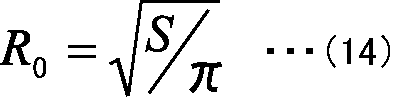
これに対して、実効値Seは、ギャップからコイル付近まで漏れ出してくる磁束の面積に対応し、磁束線の積分を矩形近似した場合の断面積と解釈することができ、次式(15)で表すことができる。

図4には、突起部3d、4dの先端部付近の断面積Sおよびその実効値、すなわち基端部付近の断面積Seの関係も示されている。
次に、規格化パラメータα,β,γについて説明する。本実施形態では、規格化パラメータα,β,γの空間が、いわゆる3元合金の相図の態様で表現でき、各規格化パラメータα,β,γの変化に対する結果が認識し易いため、規格化パラメータα,β,γを3つ設定した。ただし、本実施形態の相図では、3辺総ての目盛は、対数スケールであり、次数に応じて拡大され、逆数なら反転して示めされている。
これは、所望とするインダクタンスLの範囲が、次式(16)で表すことができることから、理想的なコア材を用いたリアクトルのパラメータをL0、g0、S0とすると、次式(17)が成り立ち、その対数をとると、次式(18)となるためである。
L=μ0・(S・N2)/g~N2・S/g ・・・(16)
L/L0~(N/N0)2・(S/S0)/(g/g0) ・・・(17)
ln(L/L0)~2ln(N/N0)+ln(S/S0)-ln(g/g0) ・・・(18)
L/L0~(N/N0)2・(S/S0)/(g/g0) ・・・(17)
ln(L/L0)~2ln(N/N0)+ln(S/S0)-ln(g/g0) ・・・(18)
この上式(18)は、前記3元合金の相図における式(19)の関係と類似しており、軸の縮尺と極性とを適宜調整することで、前記相図の態様で表現可能となる。図5は、本件発明者が作成した相図の一例である。
x+y+z=100% ・・・(19)
図5は、前記コア構造パラメータから求められる規格化パラメータの組み合わせによる相図の一例を示す図である。図5は、後述するような各パラメータα,β,γの取り得る範囲(実用域)をできるだけ拡大して示すように、前述のように軸の縮尺と極性とが適宜調整されており、各パラメータα,β,γの1の値が層図の中心に位置していない。図5には、本件発明者が実際に計算した9つのサンプルA~Iが、得られたパラメータα,β,γの各値に基づいてマッピングして示されている。そのマッピングの元となる各幾何構造パラメータ(L,N0,g,S,N,ge,Se)の計算結果が表1に示されている。

これらの表1および図5において、サンプルA~Fは、比較的パワーの小さな2輪車や、太陽光発電装置のコンバータ等を用途とする数kWレベルのサンプルであり、サンプルG~Iは、比較的パワーの大きなハイブリッドや電気の自動車等を用途とする数十kWレベルのサンプルである。
なお、表1には、突起部3d、4dの実効断面積Seの解析結果も合わせて示されている。その解析は、前述の図4で示すように、突起部3d、4dの空隙よりコイル領域まで漏れ出してくる磁束線を積分し、その積分結果を矩形近似することによって行われた。すなわち、解析には、次式(20)が用いられた。表1に記すとおり、実効Seとほぼ一致していることが理解される。
Se=∫B(r)2πr・dr/Bc ・・・(20)
表1および図5から、相図におけるマッピング位置と、実際の幾何学的なコア構造の特徴との関係をいくつか説明する。まず、サンプルAは、高級磁性鋼板のものであり、帯状の導体部材10の巻数Nは、理想の巻数N0に等しく、ギャップ長の実効値geも実際のギャップ長gに等しく、突起部3d、4dの先端部の断面積Sは、実効値Se、すなわち基端部の断面積に等しく、すなわち、α、β、γ=1である。この値を基点として、ギャップが空であれば(μc>μ0であれば)、必ずβ≧1となる。また、ギャップが狭い程、βは、1に漸近し、γも1に漸近する(β→1、γ→1)。
一方、ギャップが広く、形状が円錐台型で裾野が広い(頂上平坦部が狭い)程、γが大きくなる。また、コア2(リターンヨーク部)の磁気抵抗Ryが、ギャップの磁気抵抗Rgより大きいアンバランスな設計では、γ<1となる。さらにまた、αが1より大きくなると銅損が増加、1より小さければ銅損が減少するが、あくまでヒステリシス損(∝ΔBc∝α/β)との総和で全体損失を考えるべきである。そのため、表1には、幾何および解析パラメータとともに、一部のサンプルについて、実測損失も、サンプルAとの差分で併記している。本実施形態では、以上の事項を設計指針にして、コア2の形状が最適化される。
その形状最適化の条件として、同じインダクタンスのリアクトルでも、ヒステリシス損をより小さくする、すなわち前述のように磁束密度Bcをより小さくするためには、理想の磁束密度Bc0に対して、次式(21)であるので、これより、まず、α/β<1という条件を得ることができる。
Bc/Bc0=(μ0・N・I/ge)/(μ0・N0・I/g)
=(N/N0)/(ge/g)=α/β<1 ・・・(21)
=(N/N0)/(ge/g)=α/β<1 ・・・(21)
または、L=一定、すなわちα2・γ/β=1を用いることによって、式(21)から、α・γ>1という条件が得られる。これによって、本実施形態のリアクトルでは、コア(ヨーク)2および突起部(磁極)3d、4dの材質に応じて、必要なインダクタンスLを確保しつつ、コア2のヒステリシス損を低減し、損失を小さくすることができる幾何形状が決定される。
さらに条件を絞り込み、磁束密度Bcの低減効果が顕著となる(80%以下)範囲を規定すると、式(21)より、α/β<0.8またはα・γ>1.25が得られる。これに加えて、現実のコア材料を用いた、現実的な磁気回路設計という立場から、さらに以下の制約条件が存在する。
まず、実際の低透磁率コア材を用いる限り、制約条件は、2g>ge>g、すなわち1<β<2となる。また、ギャップ長gが最大値、すなわち突起部(磁極)3d、4dが無い場合に、磁束線が漏れたとしてもコイル外形を超えない(R/W<4)ように、Se<3S、すなわち1≦γ<3が現実解となる。さらに、巻数Nが過大になると、帯状の導体部材10の長さを過大に、断面積を過小にして、銅損の増大を招くことから、1/2<α<2とすることが好ましい。図5には、α/β<1またはα・γ>1かつ1/2<α<2、1<β<2、1≦γ<3を満足する領域が、網掛けして示されている。
このように構成することによって、磁極間隙(ギャップ長g)を比較的広く開け、空芯コイル1にまで磁束線を漏らすようにして、磁極(突起部)表面の実効断面積Seを広げ、磁極内の磁束密度Bcを低減することができる。
ところが、前記γ>1、すなわちSeの増大は、空芯コイル1の巻線部まで磁束線の漏れを許容することになるので、漏洩磁束によるコイル導体内の渦電流損を抑えるために、リアクトルD1は、帯状導体10の厚みtを表皮厚みδ以下とし、後述のように、空芯コイル1を漏洩磁束に対し略平行なフラットワイズ型とすることが好ましい。
一方、規格化パラメータα、β、γとリアクトルの特性との関係は、以下の通りである。まず、幾何構造および材料的な特徴パラメータとして、Bcをギャップの中央点またはその周辺の磁束密度の最大値とし、ギャップ長の実効値geおよび突起部(磁極)3d、4dの実効断面積Seを求めると、それぞれ、次式(22)および式(23)であり、これら2つのパラメータは、磁場解析結果から容易に求めることができる。
ge=μ0・N・I/Bc ・・・(22)
Se=∫B(r)2πrdr/Bc
(or Se=∫B(x,y)dx・dy/Bc) ・・・(23)
Se=∫B(r)2πrdr/Bc
(or Se=∫B(x,y)dx・dy/Bc) ・・・(23)
そして、これらのパラメータを用いて、電気特性は、次式(24)~式(26)で表される。
V≡L・dI/dt (Lの定義) ・・・(24)
=N・dΦ/dt (ファラデーの法則、Nを外に出している)・・・(25)
=N・Se・dB/dt(磁束を定義 Φ≡BS より) ・・・(26)
=N・dΦ/dt (ファラデーの法則、Nを外に出している)・・・(25)
=N・Se・dB/dt(磁束を定義 Φ≡BS より) ・・・(26)
したがって、単位昇圧性能当りの磁束密度変化(≒鉄損)ΔBは、次式(27)となり、バイアス電流Iに伴う平均磁束密度(≒磁気飽和の度合い≒ヒス損)Bは、次式(28)となる。
ΔB=1/(N・Se)・∫V・dt
=1/(N・Se)・ΔV ・・・(27)
B≒μ0・N・I/g ・・・(28)
=1/(N・Se)・ΔV ・・・(27)
B≒μ0・N・I/g ・・・(28)
したがって、本実施形態のリアクトルD1の設計方針は、式(16)で示す所望のインダクタンスLを確保しながら、空芯コイル1の巻数Nがより少なく、突起部(磁極)3d、4dの実効断面積Seがより大きく、ギャップの実効長ができる限り大きくなるように、適したコアおよび磁極(突起部3d、4d)の幾何形状を選ぶことによって、コア2(磁極&ヨーク)の経験磁束密度を小さくし、(純鉄特性の使用域をシフトして)鉄損(主にヒステリシス損)を低減することである。
そこで、図5および表1に戻り、サンプルAは、上述のように、高級電磁鋼板をコア材に使った従来型リアクトルの一例で、コア材体積を小さく(Sを小さく)、巻数Nを多くした設計である。これに対して、残余のサンプルB~Iは、コア2に鉄粉圧縮成形のコア材を用いたものであり、上述の設計指針に基づき、サンプルBを原型として、B→C→D→Eと改良を施したものである。これら図5および表1において、サンプルB~Gについては、より具体的なリアクトルの断面形状と、発生される磁束線とが、図6の(B)~(G)に合わせて示されている。この図6を合わせて参照することで、コア形状をよりよく理解することができる。また、サンプルB~Dについて、磁束線とともに、ギャップの中央点を通る軸直角断面での磁束密度Bcの変化を、図7の(B)~(D)に示されている。図6は、図5で示す相図に示す複数のサンプルの内、一部の具体的なリアクトルの断面形状と、発生される磁束線とを示す図である。図7は、図6の内、さらに一部のサンプルについて、磁束密度の変化を示す図である。
サンプルB、Cでは、わずかながらγが1より小さい。これは、図7から判るように、リターンヨーク部の磁束密度が高い、すなわち(主にコア部材3、4の端板3b、4bが薄いため)リターンヨーク部の磁気抵抗Ryが、ギャップの磁気抵抗Rgより大きいためであり、その分、リターンヨーク部のヒステリシス損を増大させているためである。γ<1は、前述のようにギャップとリターンヨーク部との磁気抵抗のアンバランスを意味する。また、サンプルBでは、α>1と巻数が過多なことによる銅損の増加も、損失増大に顕著に影響を与えている。
このため、サンプルCは、αを減少、すなわち巻数Nを減少させたものであり、その巻数Nの減少によって空芯コイル1がコンパクトになった分、図7(B)から(C)に示すように、コア2を拡大している(端板3b,4bを厚くしている)。しかしながら、それによって、磁束密度Bcが高まり、ヒステリシス損は、増加する。そこで、サンプルDは、図7(C)から(D)に示すように、ギャップ長gを拡大し、磁束密度Bcを低下させ、ヒステリシス損を低下させたもので、より最適な設計である。すなわち、C→Dの改善により、わずかながらγ>1となっている。
一方、サンプルEは、帯状の導体部材10のアスペクト比t/Wを大きくし、空芯コイル1を扁平にしたものである。このサンプルEは、N=N0となっており、ギャップ長の実効値geも大きくなっている。しかしながら、図6(E)において、参照符号l1で示すように、ギャップ部分の漏れ磁束は、空芯コイル1の部分に大きく入り込んで、銅損を増加させている。サンプルFは、そのサンプルEから、コア2における鉄粉の密度を低下させたものであり、そのため巻数Nが増加するとともに、ギャップ長の実効値geは小さくなっている。
また、サンプルG、H、Iは、インダクタンスLが大きな大パワー用のリアクトルであるが、α/β<0.8またはα・γ>1.25 かつ 1/2<α<2、1<β<2、1≦γ<3を満足するものである。そして、サンプルG、H、Iは、それぞれ密度が7g/cm3、6g/cm3、5g/cm3である。サンプルIは、サンプルG、Hに比べて、γ、すなわち突起部(磁極)3d、4dの形状は変わらないものの、ギャップ長の実効値geが大きくなり、巻数Nも多くなっている。サンプルD、E、Fは、特に好ましい範囲α/β<0.8またはα・γ>1.25からは外れているが、これは、小パワー用途で、電気的特性以外に、寸法や重量といった要求仕様を満たす必要があり、磁束密度Bcを下げきれないためである。
図8は、図1に示すリアクトルにおける他の第1態様のコア構造を示す斜視図である。図9は、図1で示すリアクトルにおける他の第2態様のコア構造を示す斜視図である。
なお、本実施形態のリアクトルD1には、コア2において、ヨーク部分、すなわちコア部材3、4において、磁極となる突起部3d、4d部分を除く外周部3a、4aおよび端板3b、4bの部分は、空芯コイル1の外周部を総て覆っている必要はなく、上述のようにギャップ部の磁束密度Bgよりも、ヨークの磁束密度Byを高く維持できればよい。このため、リアクトルD1は、通気のために一部を外部へ開放したかご形や、図8のリアクトルD1’で示すように、コア2’が、コの字型のコア部材3’、4’を組み合わせて構成される等してもよい。例えば、磁性材料にもよるが、ヨークは、合計で、空芯コイル1の外周部の半周以上を覆っていればよい。
また、上述のように一対のコア部材3、4は、相互に等しく形成されていれば、いずれの位置で組み合わせられてもよいが、その場合、軸方向については、外周部3a、4aの端面を密着させればよいものの、径方向にはずれが生じ易い。そこで、図9のコア部材3”(4”)で示すように、一対のコア部材3、4の外周部3a、4aにおける一方の端面に突起部3b1(4b1)を、他方の端面に対応する凹所4b2(3b2)を設けておくことで、一対のコア部材3、4における前記径方向のずれを無くすことができる。また、図9のコア部材3”(4”)のように、同じ外周部3a(4a)に、突起部3b1(4b1)および凹所3b2(4b2)のそれぞれを周方向に等ピッチ(図9では180°)で、かつそれらを交互(図9では90°)に形成しておくことで、両方のコア部材3”、4”を共用し、同じ金型で作成することができる。
また、コア部材3、4の材料としては、コストを低減するために、同一材料であることが好ましく、特に所望の磁気特性(比較的高い透磁率)を容易に実現でき、また所望の形状への成形の容易性から、該コア部材3、4は、軟磁性体粉末を成形することにより形成されたものであることが好ましい。
前記軟磁性粉末は、強磁性の金属粉末であり、より具体的には、純鉄粉、鉄基合金粉末(Fe-Al合金、Fe-Si合金、センダスト、パーマロイ等)およびアモルファス粉末、さらには、表面にリン酸系化成皮膜等の電気絶縁皮膜が形成された鉄粉等が挙げられる。これら軟磁性粉末は、アトマイズ法等によって製造可能である。また、一般に、同じ透磁率であっても、飽和磁束密度が大きいことから、前記軟磁性粉末には、前記純鉄粉、鉄基合金粉末およびアモルファス粉末等の金属材料を用いることが好ましい。
このような軟磁性粉末を、例えば公知の常套手段を用いることによって、所定の密度に圧粉成形して、コア部材3、4が得られる。この圧粉(鉄粉)コアは、例えば、図10に示す磁束密度-比透磁率特性を有している。図10は、圧粉(鉄粉)コアにおける密度別の磁束密度-比透磁率特性を示す図である。図10の横軸は、磁束密度〔T〕であり、縦軸は、比透磁率〔H/m〕である。
図10に示すように、密度6.00[g/cc]以上の部材(この例では、密度5.99[g/cc];(□)、密度6.50[g/cc];(×)、密度7.00[g/cc];(△)、密度7.50[g/cc];(◆))では、磁束密度-比透磁率特性は、比較的高い初期比透磁率から、磁束密度の増加に従い比透磁率が徐々に増加してピーク(最大値)となり、その後、磁束密度の増加に従って徐々に比透磁率が減少して行くプロファイルである。
例えば、密度約7.00[g/cc]の部材では、磁束密度-比透磁率特性は、約120[H/m]の初期比透磁率から、磁束密度が増加すると、磁束密度が0.35[T]で比透磁率が約200[H/m]まで急激に増加し、その後、磁束密度の増加に従って徐々に比透磁率が減少して行くプロファイルである。この図10に示す例(密度約7[g/cc]の)部材では、比透磁率が、初期比透磁率から磁束密度の増加に従って再び初期比透磁率となる磁束密度は、約1Tである。
また、密度約5.99[g/cc]の部材、密度約6.5[g/cc]の部材および密度約7.5[g/cc]の部材における初期比透磁率は、それぞれ、約70、約90および約160[H/m]である。このように初期透磁率が約50~250[H/m]の材料は、この例では、約70~約160[H/m]の材料は、磁束密度-比透磁率特性が略同様のプロファイルとなり、比較的高い比透磁率の材料である。
次に、図11には、リアクトルの構成と磁束線との関係を示す。図11(A)は、比較例1のリアクトルの構成を示し、図11(B)は、本実施形態におけるリアクトルD1の構成を示し、図11(C)は、比較例2のリアクトルの構成を示す。この比較例1のリアクトルは、コア2が設けられておらず、空芯コイル1のみであり、比較例2のリアクトルは、ギャップ無し、すなわち突起部(磁極)3d、4dが円柱15として、端板3b、4b間を接続する構造である。これら図11(A)ないし(C)は、半径分の軸線方向断面図である。また、図11(D)は、比較例1におけるリアクトルの磁束線図であり、図11(E)は、本実施形態におけるリアクトルD1の磁束線図であり、図11(F)は、比較例2におけるリアクトルの磁束線図である。なお、図面の視認性を考慮して、図11(D)~(F)では、隣接する巻線間の境界線の記載が省略されている。
また、図12は、本実施形態および比較例1,2のリアクトルにおいて、0~200[A]までの範囲で電流を変化させた場合のインダクタンスの変化に関する実験結果を示す図である。図12中、グラフAが比較例1のリアクトルにおけるインダクタンスの変化を示すグラフであり、グラフBが本実施形態のリアクトルD1におけるインダクタンスの変化を示すグラフであり、そして、グラフCが比較例2のリアクトルにおけるインダクタンスの変化を示すグラフである。
図12のグラフAを参照すると、比較例1のリアクトルでは、前記電流の全範囲において略一定のインダクタンスが安定的に得られている。しかしながら、図11(D)に示すように、このリアクトルでは、空芯コイル内の磁束線が軸方向に平行にならないため、渦電流損が大きくなる。そのため、図12のグラフAで示されるように、インダクタンスが絶対的に小さい。また、図11(D)に示すように、リアクトルから外部に漏出する磁束線が非常に多い。
また、図12のグラフCに示すように、比較例2のリアクトルでは、電流が比較的小さい0~約30[A]の範囲において大きなインダクタンスが得られている。また、このリアクトルは、コア2を有しているため、リアクトルから磁束線が外部に漏出することを防止または抑制することができる。しかしながら、比較例2のリアクトルでは、電流がこの範囲より大きくなると、磁性体が磁気飽和して、急激にインダクタンスが低下する。このようにインダクタンスの変化が大きいと、わずかな誤差によってインダクタンス特性が比較的大きく変化することとなるため、当該リアクトルを搭載するインバータの制御性が悪くなる。
これに対し、本実施形態のリアクトルD1では、比較例2のリアクトルと同様にコア部2の存在によって比較例2のリアクトルと同等程度にリアクトルD1から磁束線が外部に漏出することを防止または抑制することができる。また、図12のグラフBに示すように、前記電流の全範囲において、安定したインダクタンス特性が得られ、かつ、そのインダクタンスが比較例1のリアクトルの場合に対して大きいという利点を有する。
次に、本実施形態のように、帯状の導体部材10が径方向に重なるように巻回されたフラットワイズ巻線構造を有する空芯コイル1の利点について説明する。図13は、エッジワイズ巻線構造の空芯コイル1xを有するリアクトルの断面図である。図14は、フラットワイズ巻線構造およびエッジワイズ巻線構造のリアクトルにおける周波数と損失との関係を示すグラフである。図14の横軸は、周波数fであり、その縦軸は、損失である。図15は、空芯コイルを構成する導体部材のアスペクト比を説明するための図である。図15は、空芯コイル1、1yの半径分の断面形状を拡大して示している。
図13に示すエッジワイズ巻線構造のリアクトルにおいて、前述の図1等に類似し、対応する部分は、同一の参照符号を付して示し、その説明を省略する。
空芯コイル1、1xは、導体部材10から形成されているので、該空芯コイル1、1xに通電すると、一般的に、磁力線に垂直な面(直交面)に渦電流が発生し、それによって損失(ロス)が発生する。この渦電流の大きさは、磁束密度が同一である場合には、磁束線と交差する面積、すなわち、磁束方向に垂直な連続する面の面積に比例する。空芯コイル1、1x内では、磁束方向は、軸方向に沿っているので、渦電流は、該空芯コイル1、1xを形成する帯状の導体部材10における、軸方向に直交する径方向の面の面積に比例することになる。
このため、エッジワイズ巻線構造のリアクトルでは、図13に示すように、導体部材10では、径方向の面積が大きく、渦電流を生じやすいため、電気抵抗によって生じる損失よりも渦電流によって生じる損失の方が支配的となる。したがって、エッジワイズ巻線構造のリアクトルでは、通電電流の周波数に損失が依存し、図14に示すように、周波数の増加に伴い損失が増大し、比較的小さな電気抵抗によって初期損失が比較的小さくなる。
一方、本実施形態におけるリアクトルD1で採用されているフラットワイズ巻線構造では、図1に示すように、帯状の導体部材10では、径方向の面積が小さく、渦電流が生じ難い一方で、軸方向の面積が大きい。したがって、フラットワイズ巻線構造のリアクトルD1では、渦電流が殆ど生じず、図14に示すように、損失は、通電電流の周波数によらず略一定であり、比較的小さな電気抵抗によって初期損失も比較的小さくなる。
さらに、図13の矢印(⇔)で示すように、エッジワイズ巻線構造のリアクトルでは、前記導体部材10が軸方向に重ねられた構造であるが、図1に示すように、フラットワイズ巻線構造のリアクトルD1では、前記導体部材10は、その幅方向が軸方向に略一致し、連続しているため、フラットワイズ巻線構造のリアクトルD1は、エッジワイズ巻線構造のリアクトルよりも効果的に熱伝導を行うことができる。このため、前記損失および熱伝導の点でフラットワイズ巻線構造のリアクトルD1は、前記エッジワイズ巻線構造のリアクトルよりも優れている。
さらに、本実施形態では、フラットワイズ巻線構造のリアクトルD1において、図15(A)に示すように、空芯コイル1を構成する導体部材10は、その幅Wが、その径方向の長さ(以下、厚みという)t以上の帯状導体である。換言すると、本実施形態では、幅Wに対する厚みtのアスペクト比(t/W)が1以下となる矩形断面を有する導体部材10によって、リアクトルD1の空芯コイル10は、構成されている。
これにより、図15(B)に示すように、前記厚みtの方が前記幅Wより長い矩形断面を有する導体部材10yで構成された空芯コイル1yを備えるリアクトルに比して、本実施形態のリアクトルD1は、その径方向の面積が小さくなる。その結果、前記損失の点でフラットワイズ巻線構造のリアクトルD1がエッジワイズ巻線構造のリアクトルよりも優れている理由と同様の理由により、渦電流損を小さくすることができる。特に、導体部材10の厚みtに対する幅Wのアスペクト比(t/W)を1/10以下とすると、渦電流損の発生を大幅に低減することができる。
その上で、帯状の導体部材10の厚みtが、当該リアクトルD1の駆動周波数に対する表皮厚みδ以下に設定されると、渦電流損は、ほぼ確実に無くなる。表皮厚みδは、次式(29)によって表される。
δ=√(2/ωμσ) ・・・(29)
ただし、ωは、角周波数であり、μは、透磁率であり、そして、σは、電気伝導率である。
また、本実施形態のリアクトルD1では、空芯コイル1の上下両端面にそれぞれ対向するコア部材3、4の端板3b、4bの内壁面は、少なくともコイル端部を覆う領域において相互に平行に形成されている。また、これら端板3b、4bの各内壁面と、空芯コイル1の帯状導体10の幅方向とは、直交するように配置されている。これら条件が満たされない場合には、帯状導体10の断面形状にかかる条件が設定されていても、空芯コイル1の内部を通る磁束線が軸方向に平行な状態から外れて行く。そこで、本実施形態では、以下に説明するように、端板3b、4bの内壁面に、相互に平行とみなせるような平行度が定義される。
図16は、コアの平行度の算出方法の説明図である。図16に示すように、端板3b、4bの各内壁面の間隔のうち、最も内周側の位置(以下、最内周位置という)における間隔をL1、最も外周側の位置(以下、最外周位置という)における間隔をL2とする。また、最内周位置から最外周位置までの範囲における間隔の平均値をL3とする。なお、平均値L3は、最内周位置と最外周位置との間において径方向に所定間隔で刻まれた複数の位置における間隔の平均値である。この場合に、空芯コイル1の最内周位置における端板3b、4bの各内壁面の間隔L1と、最外周位置における間隔L2との差(L1-L2)を、平均値L3で除算して得られる値((L1-L2)/L3)が、前記平行度と定義される。
図17ないし図19は、本件発明者のシミュレーションによる平行度別の磁束線を示す図である。図17は、前記平行度が-1/10である場合を示し、図18は、前記平行度が1/10である場合を示し、そして、図19は、前記平行度が1/100である場合を示す。図19に示すように、平行度が1/100である場合には、空芯コイル1の内部を通る磁束線(点線で示す部分の磁束線)は、軸方向に平行になる。一方、図17および図18の矢印Q1、Q2で示すように、平行度が-1/10、+1/10である場合には、空芯コイル1の内部を通る磁束線が軸方向に平行にならない。空芯コイル1の内部を通る磁束線が平行にならない場合では、前述したように、渦電流損が大きくなり、インダクタンスが絶対的に小さくなる。
そこで、本件発明者は、平行度を種々変えつつ、磁束線の分布を検証した。その結果、本件発明者は、空芯コイル1の内部を通る磁束線を平行にするために、平行度の絶対値を1/50以下、好ましくは1/100以下に設定する必要があるとの知見を得た。さらに、本件発明者は、帯状の導体部材10の幅方向が、端板3b、4bの内壁面と直交するように配置する必要があるとの知見を得た。このように構成することによって、空芯コイル1の内部を通る磁束線が軸方向に平行となり、該帯状の導体部材10での渦電流損を小さくすることができ、インダクタンスLを大きくすることができる。したがって、帯状の導体部材10が、その幅方向に発生した磁束を、効率良くコア2に取り込むことができる。
さらに、本件発明者は、空芯コイル1の軸芯から該空芯コイル1の外周面までの半径R(図46参照)と、空芯コイル1を形成する導体部材10の幅Wとの比R/Wに着目し、比R/Wを変化させた場合における磁束線分布の態様についてシミュレーション実験を行った。図20ないし図29は、リアクトルD1の全体体積、導体部材10の矩形断面の断面積、空芯コイル1の巻数をそれぞれ一定値とした場合において、前記比R/W別の磁束線を示す図である。図20は、前記比R/Wが10である場合を示し、図21は、前記比R/Wが5である場合を示し、図22は、前記比R/Wが3.3である場合を示し、図23は、前記比R/Wが2.5である場合を示し、図24は、前記比R/Wが2である場合を示し、図25は、前記比R/Wが1.7である場合を示し、図26は、前記比R/Wが1.4である場合を示し、図27は、前記比R/Wが1.3である場合を示し、図28は、前記比R/Wが1.1である場合を示し、そして、図29は、前記比R/Wが1である場合を示す。これら図20ないし図29において、隣接する巻線間の境界線の記載は、省略されている。
これら磁束線図から判るように、前記比R/Wが5以上に設定された場合(図20および図21に示す場合)では、コア部2の外部に磁束が漏れており、周辺機器に影響を及ぼす虞があるため、実用上の問題がある。また、前記比R/Wが1.3以下に設定された場合(図27ないし図29に示す場合)では、空芯コイル1の内部を通る磁束線が軸方向に対して平行にならないため、渦電流損が大きくなり、効率が低下する虞がある。
一方、リアクトルD1を搭載するインバータが良好な制御性を有するために、電流の変化に対するインダクタンスLの変化が少なく、かつ安定していることが必要である。そこで、本実施形態では、このインダクタンスLの安定性を表す指標として、次式(30)を定義した。
安定度I(%)={(Lmax-Lmin)/Lav}×100 ・・・(30)
ただし、Lminは、前記インバータに供給し得る電流の範囲(以下、使用範囲という)のうち最小の電流におけるインダクタンス(以下、最小インダクタンスという)であり、Lmaxは、前記電流の範囲のうち最大の電流におけるインダクタンス(以下、最大インダクタンスという)であり、Lavは、前記電流の範囲における複数の電流値にそれぞれ対応する複数のインダクタンスの平均値(以下、平均インダクタンスという)である。上式(30)によれば、安定度Iの値が小さいほど、インダクタンスの安定性が高くなる。
本件発明者は、この安定度Iと、比R/Wとの関係について検討した。図30は、前記比の変化に対するインダクタンスおよびその安定度の変化を示すグラフKである。図30の横軸は、前記比R/Wであり、その紙面右側の縦軸は、前記安定度Iである。なお、この図30には、各リアクトルのインダクタンスを紙面左側の縦軸で表すことによって、比R/Wの変化に対する最大インダクタンスLmax、最小インダクタンスLminおよび平均インダクタンスLavの各変化を表すグラフも示されている。
図30に示すように、最大インダクタンスLmaxは、前記比R/Wに略比例して増大し、最小インダクタンスLminは、前記比R/Wが約6である場合に最大となる山形波形を有するように変化する。また、平均インダクタンスLavは、前記比R/Wが約8である場合に最大となる山形波形を有するように変化する。これらの結果、安定度Iは、その増加率が前記比R/Wの値に応じて異なるものの、総じて前記比R/Wが大きくなるに伴って増大する、という実験結果が得られた。
そこで、上述のようにインバータが良好な制御性能を備えるために、安定度Iを10%以下に抑えることが必要である。したがって、図30を参照すると、比R/Wは、4以下に設定することが必要である(R/W≦4)。したがって、比R/Wを、1.3以上、4以下の範囲の中から選ぶことによって、リアクトルD1は、渦電流損を抑えつつ、インダクタンスLも安定させることができる。
上述のような磁気的に等方性を有するコアを実現する場合に、コア部材3、4として軟磁性粉末を圧粉成型した圧粉コアを用いることによって、原料粉末を型に入れて成型することで所望の形状に作成することができるとともに、材料費が安く、所望の磁気特性(密度)を比較的容易に得ることができる。一方、コア部材3、4としてフェライトコアを用いることによって、原料粉末を型に入れて成型(焼成)することで所望の形状に作成することができる。なお、磁束密度が高い方が漏れ磁束を抑制でき、かつ小型化することができるため、ソフトフェライトよりも鉄系軟磁性粉末の圧粉コアが好ましい。
また、好ましくは、空芯コイル1と、少なくともコア2の端板3b、4bにおける空芯コイル1の対向面との間に、絶縁耐性をより向上させるために、絶縁部材が配置される。図31は、コアと空芯コイルとの間に絶縁部材を介在する場合の複数の態様について示す断面図である。図31(A)は、絶縁部材IS1(IS1-1、IS1-2)を備える第1態様のリアクトルD1aを示し、図31(B)は、絶縁部材IS2(IS2-1、IS2-2)を備える第2態様のリアクトルD1bを示し、そして、図31(C)は、絶縁部材IS3を備える第3態様のリアクトルD1cを示す。絶縁部材IS(IS1、IS2、IS3)は、例えばPEN(ポリエチレンナフタレート)やPPS(ポリフェニレンサルファイド)等の耐熱性を有する樹脂のシートである。
図31(A)で示すリアクトルD1aにおける絶縁部材IS1-1、IS1-2は、空芯コイル1の端部と、対向するコア部材3、4の端板3b、4bの内壁面との間に配置される。また、図31(B)で示すリアクトルD1bにおける絶縁部材IS2-1、IS2-2は、端板3b、4bに対向する部分だけでなく、空芯コイル1の内周側および外周側の一部を覆うような筒状の立ち上がり部を有する。また、図31(C)で示すリアクトルD1cにおける絶縁部材IS3は、絶縁部材IS2-1、IS2-2における立ち上がり部を延長し、相互に接続したものである。すなわち、絶縁部材IS3は、環状のチューブのように形成され、その内部に空芯コイル21が収容される。このような構成の絶縁部材ISをさらに備えることによって、空芯コイル1とコア2との間における絶縁耐力をより向上することができる。
表2は、図31(A)に示す構成のリアクトルD1aにおいて、絶縁部材IS1-1、IS1-2の材料および厚さ(μm)の変化に対する絶縁耐圧(2.0kV)の変化を示す。表2の実験では、絶縁部材IS1-1、IS1-2がカプトンシート(ポリイミド)である場合、その厚さを25μm、50μmおよび100μmにそれぞれ変え、各場合のシートに2.0kVの電圧を印加し、絶縁耐圧(絶縁が保たれているか否か)が試験された。また、絶縁部材IS1-1,IS1-2がPENシートである場合、その厚さを75μmおよび125μmにそれぞれ変え、各場合のシートに2.0kVの電圧を印加し、絶縁耐圧が試験された。そして、絶縁部材IS1-1,IS1-2がPPSおよびノーメックスである場合、それら各厚さを共に100μmとし、各場合のシートに2.0kVの電圧を印加し、絶縁耐圧が試験された。
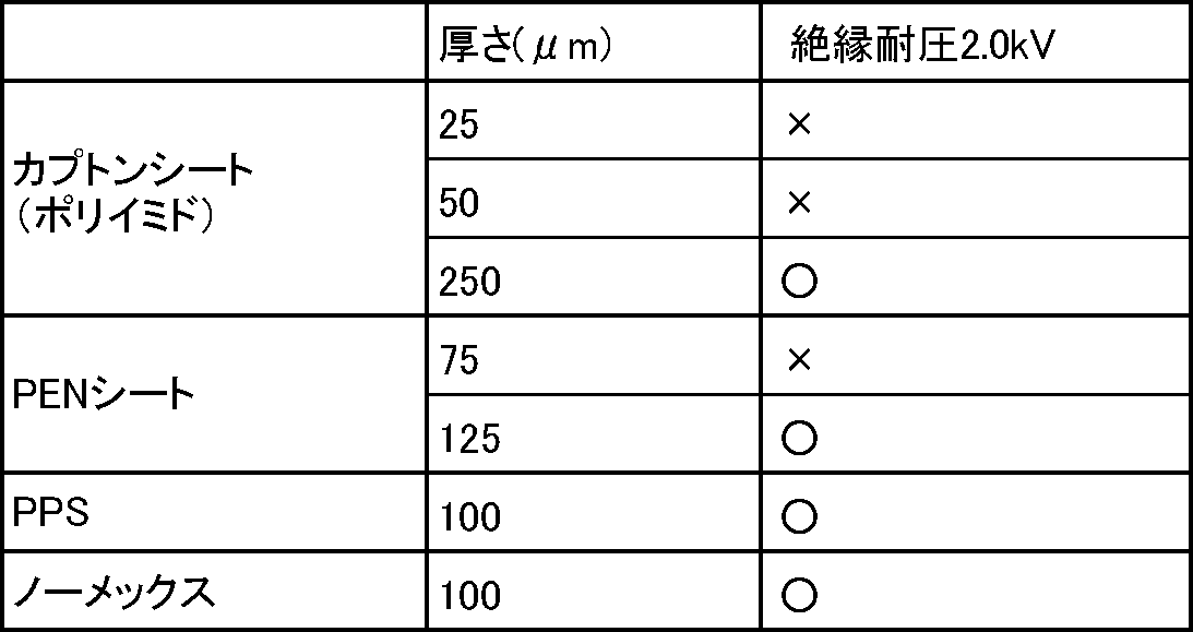
表2から分かるように、絶縁部材IS1-1、IS1-2が厚さ100μmのカプトンシート(ポリイミド)である場合、絶縁部材IS1-1、IS1-2が厚さ125μmのPENシートである場合、絶縁部材IS1-1、IS1-2が厚さ100μmのPPSである場合、および、絶縁部材IS1-1、IS1-2が厚さ100μmのノーメックスである場合に、空芯コイル1とコア2との間で良好な絶縁が得られている。したがって、絶縁部材ISの厚さは、100μm以上であることが好ましい。
あるいは、絶縁部材ISは、上述の樹脂に限らず、BN(チッ化ボロン)セラミック等が用いられてもよい。その場合、上述のようなシート体に限らず、コンパウンドの充填によって絶縁部材ISが形成されてもよい。充填は、コア部材3、4の内面に適量の充填材を塗布した後に、空芯コイル1を収容し、該コア部材3、4を接合することで実現することができる。なお、充填材の硬度は、用途仕様に依存し、その用途(硬度)によって、熱や触媒による硬化処理を必要とする場合もある。こうして、空芯コイル1とコア2との間における絶縁耐力をより向上させることができる。
また、特に充填材等によって軸方向(上下方向)の熱伝導性が良くなると、空芯コイル1で発生するジュール熱を、絶縁部材ISを介してコア部材3、4に熱伝導させ、効率良く外部に排熱することが可能となる。また、このため、外部から該コア部材3、4を冷却するように構成することによって、リアクトルD1の内部が高熱になることを一層防止することができる。
ここで、充填材に磁性体を用いる場合には、注意を要するが、磁性流体は、振動等の悪環境でも常に隙間を埋めて伝熱性能を確保することができるメリットがる。このため、低透磁性の磁性体で、効果面が大きい場合には、充填材として、低透磁性の磁性体が充填されてもよい。
次に、別の実施形態について説明する。
(第2実施形態)
図32は、第2実施形態におけるリアクトルの一部分を切り欠いて示す斜視図である。第2実施形態におけるリアクトルD2は、前述の図1で示すリアクトルD1に類似している。上述のリアクトルD1では、基本的に、空芯コイル1およびコア2は、円筒状に形成されるが、これに限定されず、四角筒状(断面四角形の筒状)、六角筒状(断面六角形の筒状)および八角筒状(断面八角形の筒状)等の多角筒状(断面多角形の筒状)に形成されてもよい。また、空芯コイル1およびコア2の一方が円筒状で、他方が多角筒状等の組み合わせも可能である。図32に示す例では、空芯コイル11およびコア12が共に四角筒状に形成されている。このため、リアクトルD2のコア12を形成するコア部材13、14における突起部13d、14dは、四角錘台状に形成され、空芯コイル11の空芯部S2は、四角筒状の空間を有する。
図32は、第2実施形態におけるリアクトルの一部分を切り欠いて示す斜視図である。第2実施形態におけるリアクトルD2は、前述の図1で示すリアクトルD1に類似している。上述のリアクトルD1では、基本的に、空芯コイル1およびコア2は、円筒状に形成されるが、これに限定されず、四角筒状(断面四角形の筒状)、六角筒状(断面六角形の筒状)および八角筒状(断面八角形の筒状)等の多角筒状(断面多角形の筒状)に形成されてもよい。また、空芯コイル1およびコア2の一方が円筒状で、他方が多角筒状等の組み合わせも可能である。図32に示す例では、空芯コイル11およびコア12が共に四角筒状に形成されている。このため、リアクトルD2のコア12を形成するコア部材13、14における突起部13d、14dは、四角錘台状に形成され、空芯コイル11の空芯部S2は、四角筒状の空間を有する。
このように本実施形態のリアクトルD2は、図32に示すように、フラットワイズ巻線構造を有する空芯コイル11と、空芯コイル11を覆うコア12とを備えて構成される。コア12を構成する一対のコア部材13、14は、磁気的に等方性を有する材料から成り、四角筒状の外周部13a、14aと、四角板状の端板13b、14bとを備えて構成される。こうして形成された四角筒状の凹所13c、14cに、空芯コイル11が収納される。端板13b、14bにおいて、空芯コイル12に対向する内壁面の中央部には、突起部13d、14dが形成される。なお、この空芯コイル12のように、多角筒状のコイルである場合には、前述の空芯コイル1における半径Rを、該空芯コイル12の中心から外周面までの最短距離と読み替える。
図33は、図32に示すリアクトルにおける磁束密度をベクトルで示す図であり、コア12を二分した軸線方向断面図である。図34は、図1に示すリアクトルと、図32に示すリアクトルとのインダクタンス特性を比較して示すグラフである。ここで、図34では、40Aでのインダクタンスが略同じになる条件で図1に示す構成のリアクトルD1と図32に示す構成のリアクトルD2とを比較している。図34の横軸は、電流[A]であり、その縦軸は、規格化インダクタンスである。
図33で示すように、四角筒状のリアクトルD2によっても、空芯コイル11内の磁束線が軸方向に略平行となり、図1に示される円筒状のリアクトルD1と同様な作用効果を有する。しかも、外形の最大寸法が同じ場合、図34から分かるように、この四角筒状のリアクトルD2のインダクタンスは、円筒状のリアクトルD1のインダクタンスよりも大きい。さらに、四角筒状のリアクトルD2のインダクタンス特性は、円筒状のリアクトルD1のインダクタンス特性と同様のプロファイルである。これらインダクタンス特性は、比較的電流値の小さい範囲(図34では約80A以下の範囲)では略一定であり、その範囲を超えると、通電電流の増加に伴って徐々に減少している。
次に、別の実施形態について説明する。
(第3実施形態)
図35は、第3実施形態のリアクトルにおけるコア部材23を内方から見た正面図である。このコア部材23は、前述のコア部材3、4に類似し、コア部材3に対応する部分には、同一の参照符号を付して示し、その説明を省略する。本実施形態のコア部材23では、冷却用の凹溝23a、23bが設けられる。凹溝23bは、突起部3dの周囲を囲む環状に形成され、凹溝23aは、複数が周方向に等間隔に設けられ、凹溝23bから外周側に向けて放射状に延び、筒部3aを貫通して外部へ開放している。そして、空気や冷却水等の冷却媒体は、凹溝23bを交互に供給および排出される。あるいは、冷却媒体は、一直径線を境界に2つに分割された一方領域に設けられた凹溝23bから供給され、他方領域に設けられた凹溝23bから排出される。このような凹溝23a、23bを設けることによって、コアを強制冷却することができ、これにより、リアクトルの放熱性能を向上することができる。
図35は、第3実施形態のリアクトルにおけるコア部材23を内方から見た正面図である。このコア部材23は、前述のコア部材3、4に類似し、コア部材3に対応する部分には、同一の参照符号を付して示し、その説明を省略する。本実施形態のコア部材23では、冷却用の凹溝23a、23bが設けられる。凹溝23bは、突起部3dの周囲を囲む環状に形成され、凹溝23aは、複数が周方向に等間隔に設けられ、凹溝23bから外周側に向けて放射状に延び、筒部3aを貫通して外部へ開放している。そして、空気や冷却水等の冷却媒体は、凹溝23bを交互に供給および排出される。あるいは、冷却媒体は、一直径線を境界に2つに分割された一方領域に設けられた凹溝23bから供給され、他方領域に設けられた凹溝23bから排出される。このような凹溝23a、23bを設けることによって、コアを強制冷却することができ、これにより、リアクトルの放熱性能を向上することができる。
次に、別の実施形態について説明する。
(第4実施形態)
図36ないし図38は、第4実施形態における各態様のリアクトルの軸線方向断面図である。図36は、第1態様のリアクトルD4aを示し、図37は、第2態様のリアクトルD4bを示し、そして、図38は、第3態様のリアクトルD4cを示す。これら各図の(A)は、全体構成を示し、各図の(B)は、図36(A)ないし図38(A)において、空芯コイル1付近を拡大して示す断面図である。
図36ないし図38は、第4実施形態における各態様のリアクトルの軸線方向断面図である。図36は、第1態様のリアクトルD4aを示し、図37は、第2態様のリアクトルD4bを示し、そして、図38は、第3態様のリアクトルD4cを示す。これら各図の(A)は、全体構成を示し、各図の(B)は、図36(A)ないし図38(A)において、空芯コイル1付近を拡大して示す断面図である。
これらリアクトルD4a、D4b、D4cは、前述の図1で示すリアクトルD1および図31(C)で示すリアクトルD1cに類似し、対応する部分には同一の参照符号を付して示し、その説明を省略する。これらリアクトルD4a、D4b、D4cは、コア2の外部に、ヒートシンクHSをさらに備えている。
コア2を構成するコア部材3、4の一方(図36ないし図38ではコア部材4)は、伝熱部材PG1を介して、ヒートシンクHSに固定される。コア部材3、4の両方にヒートシンクHSが設けられてもよい。このように構成することによって、リアクトルD4a、D4b、D4cで生じた熱を外部へ放熱することができる。
そして、リアクトルD4a、D4b、D4cでは、空芯コイル1を構成する帯状の導体部材10間を絶縁するために用いられる絶縁材が、端面側にも設けられ、該空芯コイル1の熱をコア部材3、4へ熱伝導する伝熱部材としても用いられている。より具体的には、図36で示す第1態様のリアクトルD4aでは、空芯コイル1の一端側(ヒートシンクHS側)に伝熱部材PG2が設けられ、図37で示す第2態様のリアクトルD4bでは、空芯コイル1の他端側(ヒートシンクHSとは反対側)にもさらに伝熱部材PG3が設けられ、図38で示す第3態様のリアクトルD4cでは内部の空間に総て伝熱部材PG4が充填されている。伝熱部材PG(PG1~PG4)は、空芯コイル1の熱をコア部3、4に熱伝導するための部材であり、比較的高い熱伝達係数を有する材料であることが好ましく、そして、空芯コイル1とコア部3、4とを密着させることが好ましい。伝熱部材PG1~PG4には、伝熱グリス等が用いられる。
このような伝熱部材PG1~PG4をさらに介在することで、空芯コイル1で発生した熱を、コア部材3、4を介して、ヒートシンクHSへさらに効率的に伝導することができる。これによって、導体部材10間を絶縁するために用いられる絶縁材の絶縁性の低下(劣化)を防ぎ、該絶縁材の絶縁性を維持することが可能となる。
より詳しくは、帯状導体10間の絶縁や絶縁部材IS3としては、前述の表2で示すように、ポリイミドやPEN等の樹脂材料が用いられる。そこで、ヒートシンクHSのみが設けられ、空芯コイル1とコア部材3、4との間に伝熱部材PG1~PG3が設けられない構成の場合、リアクトルに通電される電力量によっては、リアクトルの温度がこれら樹脂の耐熱温度を超えてしまう場合がある。しかしながら、図36ないし図38に示すように、ヒートシンクHSおよび伝熱部材PG1~PG4が設けられる場合には、リアクトルD4a、D4b、D4cの温度は、高くても140℃程度で略定常状態(熱平衡状態)となり、これらの樹脂材料の耐熱温度以下に維持することができる。伝熱部材PG1~PG4の熱伝導率は、0.2〔W/mK〕以上であることが好ましく、1.0〔W/mK〕以上であることがより好ましい。また、上述では、放熱構造をリアクトルD1に適用した例について説明したが、リアクトルD2に適用した場合も同様に説明することができる。
次に、別の実施形態について説明する。
(第5実施形態)
図39および図40は、第5実施形態におけるリアクトルの正面図および断面図である。図39(A)および図40(A)は、正面図であり、図39(B)および図40(B)は、それぞれ、図39(A)および図40(A)における切断面線A1-A1およびA2-A2から見た断面図である。このリアクトルD5は、ヒートシンクHSを備えている点で前述の図36ないし図38に示すリアクトルD4a、D4b、D4cに類似しているが、伝熱部材PG1~PG4がさらに設けられていてもよい。
図39および図40は、第5実施形態におけるリアクトルの正面図および断面図である。図39(A)および図40(A)は、正面図であり、図39(B)および図40(B)は、それぞれ、図39(A)および図40(A)における切断面線A1-A1およびA2-A2から見た断面図である。このリアクトルD5は、ヒートシンクHSを備えている点で前述の図36ないし図38に示すリアクトルD4a、D4b、D4cに類似しているが、伝熱部材PG1~PG4がさらに設けられていてもよい。
このリアクトルD5では、コア32が、磁気的に等方性を有する材料から成る2つのコア部材33、34を組み合わせて成る場合に、ヒートシンクHSは、それらのコア部材33、34を取り付けるための基台として用いられる。その取付けには、空芯コイル1を収容した状態で2つのコア部材33、34が、締結部材であるボルト35およびナット36によって相互に締結された後に、固定部材であるボルト37によってヒートシンクHSに固定される。そして、これらボルト35およびナット36と、ボルト37とが、互いに異なる位置に配置される。図39および図40に示す例では、コア部材33、34の中心にはボルト35およびナット36の組み合わせが配置されるとともに、ボルト35およびナット36ならびにボルト37は、それぞれ周方向に等間隔(120°)に配置されるとともに、ボルト35およびナット36とボルト37とは、交互(60°毎)に配置されている。これによって、ボルト35およびナット36ならびにボルト37は、それぞれ、正三角形の各頂点に配置されることになり、安定的に締結を行うことができる。また、ボルト35の孔39には、適宜に座ぐりが施されている。ボルト35の孔39およびボルト37の孔40を形成するために、コア部材33、34は、外形円筒形状の空芯コイル1と相似な同形状ではなく、外形円筒形状の空芯コイル1とは別の、一方端部を閉塞した六角筒状に形成される。
このようにコア部材33、34の組み合わせ用の孔39と、ヒートシンクHSへの固定用の孔40とを異なる位置に形成することで、リアクトルD5の組み立てや取り付けの生産性を向上することができる。より詳しくは、コア部材をクランプ等で仮止めする方法では、仮止めした後、リアクトルを基台に固定する際には、クランプを外して固定する必要があり、組み立ての生産性が低くなる。ボルトとナットとで仮止めを行う場合も同様に、仮止めを解いた後に、リアクトルを基台に固定しなければならない。
なお、前述の伝熱部材PG1~PG4が設けられ、かつその伝熱部材PG1~PG4が硬化性樹脂である場合には、ボルト35およびナット36によってコア部材33、34が締結された状態で、加熱炉等の硬化を行う装置に搬入することができ、面積の大きなヒートシンクHSと一体化されていない分、取り扱いが容易である。基台として、ヒートシンクHSに代えて、筐体等が用いられてもよい。
次に、別の実施形態について説明する。
(第6実施形態)
図41は、本発明の実施の第6の形態にかかるリアクトルに用いられる帯状の導体部材10’を説明するための図である。図41(A)は、斜視図であり、図41(B)は、図41(A)の切断面線B-Bから見た断面図であり、図41(C)は、前述の帯状の導体部材10の模式図であり、図41(D)は、第6実施形態における帯状の導体部材10’の模式図である。前述の帯状の導体部材10は、一様な中実導体で形成されているのに対し、本第6実施形態の帯状の導体部材10’は、導体層101と絶縁層102とを厚み方向に積層したものを複数組積層(図41に示す例では、4層の導体層101間に、3層の絶縁層102が挟み込まれている)するとともに、長手方向における各端部103を、コア2の外部において、隣り合う導体層同士が絶縁層102を挟むことなく短絡される。
図41は、本発明の実施の第6の形態にかかるリアクトルに用いられる帯状の導体部材10’を説明するための図である。図41(A)は、斜視図であり、図41(B)は、図41(A)の切断面線B-Bから見た断面図であり、図41(C)は、前述の帯状の導体部材10の模式図であり、図41(D)は、第6実施形態における帯状の導体部材10’の模式図である。前述の帯状の導体部材10は、一様な中実導体で形成されているのに対し、本第6実施形態の帯状の導体部材10’は、導体層101と絶縁層102とを厚み方向に積層したものを複数組積層(図41に示す例では、4層の導体層101間に、3層の絶縁層102が挟み込まれている)するとともに、長手方向における各端部103を、コア2の外部において、隣り合う導体層同士が絶縁層102を挟むことなく短絡される。
このように構成することによって、図41(C)および(D)で示すように、渦電流の大きさは、磁束密度が同一である場合には、磁力線(磁束線)に垂直な連続する面(一続きの面)の面積に比例することから、1本の導体として巻回される前述の導体部材10を、この導体部材10’のように磁力線(磁束線)に垂直に交差する方向で複数層に分割形成することによって、渦電流の大きさを小さくすることができる。したがって、導体断面積、すなわち流すことができる電流量は、減少するものの、渦電流損をさらに小さくすることができるとともに、同じ磁束を発生させても、空芯コイルの電気抵抗も小さくすることができる。
次に、別の実施形態について説明する。
(第7実施形態)
図42ないし図44は、第7実施形態におけるリアクトルに用いられる各態様の空芯コイルを説明するための図である。図42は、第1態様の空芯コイルを示し、図43は、第2態様の空芯コイルを示し、そして、図44は、第3態様の空芯コイルを示す。
図42ないし図44は、第7実施形態におけるリアクトルに用いられる各態様の空芯コイルを説明するための図である。図42は、第1態様の空芯コイルを示し、図43は、第2態様の空芯コイルを示し、そして、図44は、第3態様の空芯コイルを示す。
第7実施形態において、この空芯コイル1”における帯状の導体部材10”は、前述の帯状の導体部材10’に類似している。すなわち、この導体部材10”は、複数の導体層101と絶縁層102とを厚み方向に積層したものを複数組積層(図42に示す例では、2層の導体層101間に、1層の絶縁層102が挟み込まれている)するとともに、長手方向における2つの端部の内、巻回された状態でコア2外に引き出される外周側の端部103が短絡される。一方、導体部材10”の内周側の端部104は、各導体層101自体が、あるいは各導体層101からそれぞれ別々に口出しされたリード線105が、コア2の外部に設けられたインダクタコア106に互いに逆相になるように経由されてから、接続点107で接合される。
このように構成することによって、まず、前述の通り、渦電流の大きさは、磁束密度が同一である場合には、磁力線(磁束線)に垂直な連続する面(一続きの面)の面積に比例することから、1本の導体として巻回される前述の帯状導体10を、この帯状導体10”のように磁力線(磁束線)に垂直に交差する方向で複数層に分割形成することによって、渦電流の大きさを小さくすることができる。ここで、渦電流は、磁場中では線材の表裏で逆方向に流れ、磁場が減少するにつれて徐々に導体内をリターンし、また磁場の交差状況が変化するところで突然に導体内をリターンする。そのため、コイル中心付近において発熱が顕著となる傾向がある。そこで上述のようにコア2の外部において、端部103および接続点107が接合されることで、コア2から離れた場所で渦電流のリターンを生じさせることができて、空芯コイル1”内部の発熱を防止することができる。
一方、インダクタコア106は、逆位相の渦電流にのみ大きな抵抗として働き、その電流を抑制するが、同位相で流れてくる駆動電流には何ら影響を与えない。したがって、複数層に分割形成された導体層101が、インダクタコア106を互いに逆相になるように経由した後、接続点107で接合されることで、さらに効果的に渦電流損を小さくすることができる。
なお、図42は、導体層101が2層の例であり、さらに多層の場合には、インダクタコア106および接続点107が複数になる。図43には導体層101が3層の例が示されており、図44には導体層101が4層の例が示されている。3層の例では、インダクタコア106が2つ設けられ、一方のインダクタコア106-1により、第1導体層101-1を流れる電流と第2導体層101-2を流れる電流とを互いに逆相とする。また、他方のインダクタコア106-2により、第3導体層101-3を流れる電流と一方のインダクタコア部106を経由した第2導体層101-2を流れる電流とを互いに逆相とした後、各インダクタコア106-1,106-2を流れた電流を接続点107で合流させている。
導体層101が4層の場合には、インダクタコア106が3つ設けられる。そして、第1のインダクタコア106-1により、第1導体層101-1を流れる電流と第2導体層101-2を流れる電流とを互いに逆相とした後、接続点107-1でそれらの電流を合流させる。さらに、第2のインダクタコア106-2により、第3導体層101-3を流れる電流と第4導体層101-4を流れる電流とを互いに逆相とした後、接続点107-2でそれらの電流を合流させる。そして、それぞれ合流されてなる2つの電流を、第3のインダクタコア106-3により互いに逆相とした後、接続点107-3で合流させている。
ここで、帯状の導体部材10が厚さ0.6mmの単層であり、空芯コイル1の巻き数が32ターンである図1に示す構造のリアクトルD1の渦電流損が調べられた。また、導体層101が厚さ0.3mmの2層であり、コア2の外部において各導体層101-1、101-2の端部が接合された構成の第1複層リアクトルの渦電流損が調べられた。また、導体層101が同様に厚さ0.3mmの2層であるものの、各導体層101-1、101-2からそれぞれ別々に口出しされたリード線105が、コア2の外部に設けられたインダクタコア106に互いに逆相になるように経由してから接合される構成の第2複層リアクトルの渦電流損が調べられた。渦電流損は、より具体的にはLCRメータを用いて、10kHzの場合における抵抗値で測定される。
その結果、第1複層リアクトルでは渦電流損が単層(基本)の場合の約56%に、第2複層リアクトルでは渦電流損が単層(基本)の場合の約32%に、それぞれ低減することができていた。こうして、帯状導体10を多層に分割形成し、さらにインダクタコア106を用いることによって、渦電流損を低減することができる。
次に、別の実施形態について説明する。
(第8実施形態)
図45は、第8実施形態にかかるリアクトルを模式的に示す平面図である。一般に、リアクトルは、変圧器として用いることが可能であり、例えば日本国特開2001-345224号公報に開示された三相変圧器がある。その三相変圧器は、ケーブル巻き線型である。その三相変圧器には、U相、V相およびW相の三相に対応する3個の鉄心の上部と下部とに鉄心ヨークが設けられることによって、磁気回路が形成されている。このような鉄心が、角のある数字の“8”の字の形に組み合わされることによって、磁力線の導線が構成されている。このような構成の三相変圧器(リアクトル)は、電力伝送系統の途中に配置され、電圧の安定化に役立つ。また、近年のインバータ技術の進歩により、保守の必要を低減するために、工場や自動車等に、交流電動機が配置されるようになってきている。その交流電動機へ、インバータから3本の三相交流の動力電線が配線されることになるが、力率改善のために、通常、それらの間に、三相変圧器(リアクトル)が直列に接続される。
図45は、第8実施形態にかかるリアクトルを模式的に示す平面図である。一般に、リアクトルは、変圧器として用いることが可能であり、例えば日本国特開2001-345224号公報に開示された三相変圧器がある。その三相変圧器は、ケーブル巻き線型である。その三相変圧器には、U相、V相およびW相の三相に対応する3個の鉄心の上部と下部とに鉄心ヨークが設けられることによって、磁気回路が形成されている。このような鉄心が、角のある数字の“8”の字の形に組み合わされることによって、磁力線の導線が構成されている。このような構成の三相変圧器(リアクトル)は、電力伝送系統の途中に配置され、電圧の安定化に役立つ。また、近年のインバータ技術の進歩により、保守の必要を低減するために、工場や自動車等に、交流電動機が配置されるようになってきている。その交流電動機へ、インバータから3本の三相交流の動力電線が配線されることになるが、力率改善のために、通常、それらの間に、三相変圧器(リアクトル)が直列に接続される。
以下に、自動車用のインバータについて述べる。近年のハイブリッド自動車等の動力源の主流は、永久磁石を内蔵する同期交流電動機である。乗り心地を向上する観点から、この電動機には回転の滑らかさが要求される。永久磁石型同期交流電動機は、例えば回転子側の磁極数が4で、固定子側の磁極数が6である組合せ(4対6)を基本とする。現実的には、回転子側の磁極数が8で、固定子側の磁極数が12である組合せ(8対12)や、回転子側の磁極数が16で、固定子側の磁極数が24である組合せ(16対24)が用いられている。そして、極数の増加に従ってトルク変動、いわゆるコギングトルクが緩和され、振動発生が抑えられて乗り心地の向上に繋がっている。
そして、上述のように回転子と固定子との磁極数が異なるため、回転子の回転に伴って、U相、V相およびW相の励磁コイルインダクタンスが非対称に変化する。その結果、インバータから印加される三相交流電圧波形に歪みが生じ、理想とする正弦波波形とならないため、トルク変動が起きてしまう。そのため、ハイブリッド自動車等に車載される車載インバータと電動機との間に、三相リアクトルを挿入することによって、非線形インダクタンスに起因する不要な電圧波形を、すなわち、高調波電圧成分を吸収して緩和する対策が有効である。
しかしながら、上述した従来の三相変圧器は、その形状特性から、比較的体格が大きく、搭載スペースに限界がある自動車へ搭載する際に不都合である。そこで、本実施形態のリアクトルD8では、絶縁材料で絶縁被覆された長尺の導体部材を巻回して形成される単層コイルを基本単位として、図45に示すように、U,V,Wの各相に対応した3個の単層コイル51u,51v,51wを厚み方向に積層して形成された3層空芯コイル51が使用される。これら3個の単層コイル51u,51v,51wの巻き始め端は、互いに電流線路の第1端子51au,51av,51awとして独立している。また、これら3個の単層コイル51u,51v,51wの巻き終わり端も、電流線路の第2端子51bu,51bv,51bwとして、互いに独立している。
そして、これら3個の単層コイル51u,51v,51wは、電気絶縁フィルムで電気的に絶縁されつつ厚み方向に積層され、コア2内に緊結に固定される。長尺な帯状の導体部材10の断面は、積層し易いように、平角形状であることが好ましい。これら積層された3個の単相コイル51u,51v,51wは、電気的には絶縁されているため導通しないが、積層による近接効果で磁気的には相互結合しており、従来の三相リアクトルのように磁気回路を形成している。
このようにリアクトルD8を構成することによって、1個分のコイルスペースに三相分のコイルが収容可能であるので、同じ電力容量の従来型の三相リアクトルに較べて、体格を小さくすることができる。このような構成のリアクトルD8は、特に、搭載スペースの限られた電気自動車、ハイブリッド自動車、電車およびバス等の移動体(車両)に搭載される場合に好適である。また、このような構成のリアクトルD8は、インバータから交流電動機への動力線において、インバータからの高調波歪電圧(いわゆるリップル)を吸収して平滑化することができ、この結果、正弦波波形に近い波形を電動機へ出力することができる。このことにより、高調波の電動機への流入が抑制され、リップル電圧、サージ電圧の発生を抑制でき、異常電流による機器の損傷を防ぐことができる。ひいては、インバータ出力素子の耐電圧を下げることができ、より安価な部品(素子)を使うことが可能となる。さらに、交流電動機で発生する逆起電力に起因する異常な逆電圧が、インバータに逆流することを途中で吸収し、インバータ出力素子の損傷も防ぐことが可能となる。また、このような構成のリアクトルD8は、電気絶縁フィルムとともに三相分のコイル51u,51v,51wが緊結に固定されるので、構造体として高い剛性を備えており、交流電流の印加によって生じる磁気力収縮振動を抑制することもできる。
本明細書は、上記のように様々な態様の技術を開示しているが、そのうち主な技術を以下に纏める。
一態様にかかるリアクトルは、帯状の導体部材を、該導体部材の幅方向が該コイルの軸方向に沿うように巻回することによって形成された空芯コイルと、磁気的に等方性を有する材料から形成され、前記空芯コイルの外側に配置されたコアとを備え、前記コアは、前記空芯コイルの外周の少なくとも一部を覆う外周部と、前記空芯コイルの両端部の少なくとも一部を覆う径部と、前記径部の中央に形成されて前記空芯コイルの空芯部に入り込み、磁束を通過させる突起部とを含み、前記突起部の先端またはその近傍の断面積をSとし、前記突起部間のギャップの長さであるギャップ長をgとし、前記ギャップの透磁率をμ0とし、該リアクトルの目標インダクタンスをLとし、前記空芯コイルにおける帯状の導体部材の巻数をNとし、コイル電流がIの場合における前記ギャップの中央点またはその近傍における平均の磁束密度をBcとする場合に、理想巻数N0、実効ギャップ長geおよび実効(突起基端部)断面積Seを、それぞれ、N0=√(L・g/μ0/S)、ge=μ0・N・I/Bc、Se=L・ge/μ0/N2と定義して求め、さらに、α=N/N0、β=ge/g、γ=Se/Sと定義される規格化パラメータα、β、γを求め、α/β<1を満足するように、コアおよび突起部の材料の透磁率に応じた、前記巻数N、前記突起部の先端断面積S、前記突起部の高さおよび前記突起部の裾野形状が設定されている。
また、他の一態様にかかるリアクトルは、帯状の導体部材を、該導体部材の幅方向が該コイルの軸方向に沿うように巻回することによって形成された空芯コイルと、磁気的に等方性を有する材料から形成され、前記空芯コイルの外側に配置されたコアとを備え、前記コアは、前記空芯コイルの外周の少なくとも一部を覆う外周部と、前記空芯コイルの両端部の少なくとも一部を覆う径部と、前記径部の中央に形成されて前記空芯コイルの空芯部に入り込み、磁束を通過させる突起部とを含み、前記突起部の先端またはその近傍の断面積をSとし、前記突起部間のギャップの長さであるギャップ長をgとし、前記ギャップの透磁率をμ0とし、該リアクトルの目標インダクタンスをLとし、前記空芯コイルにおける帯状の導体部材の巻数をNとし、コイル電流がIの場合における前記ギャップの中央点またはその近傍における平均の磁束密度をBcとする場合に、理想巻数N0、実効ギャップ長geおよび実効(突起基端部)断面積Seを、それぞれ、N0=√(L・g/μ0/S)、ge=μ0・N・I/Bc、Se=L・ge/μ0/N2と定義して求め、さらに、α=N/N0、β=ge/g、γ=Se/Sと定義される規格化パラメータα、β、γを求め、前記目標インダクタンスLが一定との条件で、α・γ>1を満足するように、コアおよび突起部の材料の透磁率に応じた、前記巻数N、前記突起部の先端断面積S、前記突起部の高さおよび前記突起部の裾野形状が設定されている。
例えば、リアクトルの損失の多くがヒステリシス損である場合には、ヒステリシス損は、コア材中の磁束密度に比例して増加し、飽和磁束密度Bsで最大となる。このため、前記リアクトルに所望の目標インダクタンスLが定められた場合に、それを確保できる範囲で、前記コア材中の磁束密度Bcを小さくすることによって、前記ヒステリシス損を小さくすることができる。
そこで、上記構成では、有効巻数N0、実効ギャップ長geおよび突起基端部断面積Seの各パラメータが、それぞれ、N0=√(L・g/μ0/S)、ge=μ0・N・I/Bc、Se=L・ge/μ0/N2と定義され、求められる。さらに、α=N/N0、β=ge/g、γ=Se/Sで表される規格化パラメータα,β,γが定義される。そして、α/β<1を満足するように、あるいは、前記目標インダクタンスLが一定との条件で、α・γ>1を満足するように、コアおよび突起部の材料の透磁率μcに応じた磁束密度Bcから、巻数N、突起部の先端付近の断面積Sが選ばれ、突起部の高さ(ギャップ長g)および突起部の裾野形状(実効断面積Se)が設定される。例えば、ギャップ長を小さくすると(突起部を高くすると)、β=ge/gが小さく、裾野を広くすると、γ=Se/Sが大きくなる。
したがって、上記構成では、コアおよび突起部の材質に応じて、必要なインダクタンスを確保しつつ、コアのヒステリシス損を低減し、損失を小さくすることができる幾何形状が決定され、このため、上記構成のリアクトルは、必要なインダクタンスを確保しつつ、コアのヒステリシス損を低減することができる。
また、他の一態様では、これら上述のリアクトルにおいて、好ましくは、α/β<0.8またはα・γ>1.25 かつ 1/2<α<2、1<β<2、1≦γ<3を満足する。
上記構成によれば、磁極間隙(ギャップ長g)を比較的広く開け、空芯コイルの巻線部分にまで磁束線を漏らすようにして、磁極(突起部)表面の実効断面積Seを広げる。この結果、上記構成のリアクトルは、磁極内の磁束密度Bcを低減することができる。
また、他の一態様では、これら上述のリアクトルにおいて、好ましくは、前記一対の径部の対向面において、少なくとも前記空芯コイルの端部を覆う領域は、相互に平行に形成され、前記帯状導体の幅方向は、前記径部の面方向と直交するように配置される。
上記構成によれば、帯状の導体部材の幅方向がその径部の面方向と直交するように配置されることによって、空芯コイルの内部を通る磁束線が軸方向に平行となる。この結果、上記構成のリアクトルは、該導体部材での渦電流損を小さくでき、インダクタンスLを大きくすることができる。
したがって、導体部材が、その幅方向に発生した磁束を、効率良くコアに取り込むことができる。
また、他の一態様では、これら上述のリアクトルにおいて、好ましくは、前記空芯コイルの中心から外周までの半径をRとし、前記帯状の導体部材の幅をWとする場合に、比R/Wが、1.3以上、4以下の条件を満足する。
上記構成によれば、前記の比R/Wが4より大きく設定される場合にはコアの外部に磁束が漏れ、また1.3未満に設定される場合には空芯コイルの内部を通る磁束線が軸方向に対して平行にならない。一方、リアクトルを搭載する例えばインバータ等の装置が良好な制御性を有するために、電流の変化に対するインダクタンスの変化が少なく、かつ安定していることが必要であり、前記装置に供給し得る電流の範囲におけるインダクタンスの安定度が10%以下に抑えられる値は、前記比R/Wが4以下である。
したがって、前記比R/Wを、1.3以上、4以下に選ぶことで、渦電流損を抑えつつ、インダクタンスも安定させることができる。
また、他の一態様では、これら上述のリアクトルにおいて、好ましくは、前記帯状の導体部材の幅Wに対する厚みtの比t/Wは、1/10以下の条件を満足する。
上記構成によれば、帯状の導体部材は、アスペクト比が大きいテープ状の導体であるので、厚みtが当該リアクトルの駆動周波数に対する表皮厚み以下となり易く、渦電流損を低減することができる。
また、他の一態様では、これら上述のリアクトルにおいて、好ましくは、前記帯状の導体部材の厚みtは、当該リアクトルの駆動周波数に対する表皮厚みδ以下の条件を満足する。
上記構成によれば、ほぼ確実に渦電流損を無くすことができる。
また、他の一態様では、これら上述のリアクトルにおいて、好ましくは、前記コアの相互に対向する径部において、最も内周側の位置における間隔をL1とし、最も外周側の位置における間隔をL2とし、最内周位置から最外周位置までの範囲における間隔の平均値をL3とする場合に、((L1-L2)/L3)で得られる値を平行度と定義し、該平行度の絶対値は、1/50以下、より好ましくは1/100以下の条件を満足する。
上記構成によれば、空芯コイルの内部を通る磁束線が軸方向に平行となり、該帯状導体での渦電流損を小さくでき、インダクタンスを大きくできる。したがって、帯状の導体部材が、その幅方向に発生した磁束を、効率良くコアに取り込むことができる。
また、他の一態様では、これら上述のリアクトルにおいて、好ましくは、前記帯状の導体部材は、導体層と絶縁層とを厚み方向に積層したものを複数組積層するとともに、長手方向における各端部を、前記コアの外部において隣り合う導体層同士が短絡されて成る。
上記構成によれば、渦電流の大きさは、磁束密度が同一である場合には、磁力線(磁束線)に垂直な連続する面(一続きの面)の面積に比例することから、1本の導体として巻回されるべき前記帯状導体を、磁力線(磁束線)に垂直に交差する方向で複数層に分割形成し、両端で並列に短絡する。したがって、上記構成のリアクトルは、渦電流損をさらに小さくすることができるとともに、同じ磁束を発生させても、空芯コイルの電気抵抗も小さくすることができる。
また、他の一態様では、これら上述のリアクトルにおいて、好ましくは、前記帯状の導体部材は、導体層と絶縁層とを厚み方向に積層したものを複数組積層するとともに、前記各導体層の長手方向における各端部において、各導体層自体が、あるいは各導体層からそれぞれ別々に口出しされたリード線が、前記コアの外部に設けられたインダクタコアに相互に逆相になるように系有されてから接続される。
上記構成によれば、両端が個別に引き出されて、コアの外部に設けたインダクタコアに互いに逆相になるように経由してから接合される。ここで、インダクタコアは、逆位相の渦電流にのみ大きな抵抗として働き、渦電流を抑制するが、同位相で流れてくる駆動電流に対しては何ら影響を与えない。したがって、上記構成のリアクトルは、渦電流損をさらに小さくすることができるとともに、同じ磁束を発生させても、空芯コイルの電気抵抗も小さくすることができる。
また、他の一態様では、これら上述のリアクトルにおいて、好ましくは、前記空芯コイルは、長尺な帯状の導体部材を絶縁材料で絶縁被覆したものを巻回して形成される単層コイルを3段積層して形成されるものであって、各単層コイルの巻き始め端は、電流線路の第1端子として互いに独立しているとともに、巻き終わり端は、電流線路の第2端子として互いに独立している。
上記構成によれば、前記3個の単層コイルは、積層による近接効果で磁気的には相互結合しており、例えば三相交流における各相の電流を流すことで、従来の三相リアクトルのような磁気回路を形成することができる。したがって、上記構成のリアクトルは、各空芯コイルが個別のコアに収容されるのではなく、単一のコアに収容されるので、同じ電力容量の従来型の三相リアクトルに較べて、体格を小さくすることができる。このため、上記構成のリアクトルは、特に、搭載スペースの限られた電気自動車、ハイブリッド自動車、電車およびバス等の移動体(車両)に搭載される場合に好適である。また、上記構成のリアクトルは、インバータからモータへの動力線において、インバータからの高調波歪電圧(いわゆるリップル)を吸収して平滑化することができ、この結果、正弦波波形に近い波形をモータへ出力することもできる。
また、他の一態様では、これら上述のリアクトルにおいて、好ましくは、前記空芯コイルと、少なくとも前記コアの径部における空芯コイルの対向面との間に、絶縁部材が配置される。
上記構成によれば、空芯コイルとコア部との間における絶縁耐力をより向上させることができる。
また、他の一態様では、これら上述のリアクトルにおいて、好ましくは、前記コアは、前記磁気的に等方性を有する材料から形成される複数のコア部材と、前記コア部材が取り付けられる基台と、前記空芯コイルを収容した状態で前記複数のコア部材を相互に締結させる締結部材と、締結されたコア部材を前記基台に固定する固定部材とを備え、前記コア部材において、前記固定部材の配設位置と締結部材の配置位置とは、互いに異なる。
上記構成によれば、コア内に空芯コイルを収容するために、コアは、複数のコア部材で形成され、それらのコア部材は、前記空芯コイルを収容した状態で一体に組み上げられる。その際、前記組み上げを行うために、締結部材が必要になり、一方、組み立てたコア部材を基台に固定するために、固定部材が必要となる。そこで、上記構成のリアクトルでは、前記締結部材と固定部材とが、例えば周方向に交互に配置されたり、中心部と周辺部とに分けて配置されたりする。したがって、上記構成のリアクトルは、その組み立てや取り付けの生産性を向上することができる。
また、他の一態様では、これら上述のリアクトルにおいて、好ましくは、前記コアは、軟磁性粉末が圧粉成型された圧粉コアで形成される。
上記構成によれば、上述のような磁気的に等方性を有するコアを実現する場合に、原料粉末を型に入れて成型することで、所望の形状に作成することができる。また、圧粉コアの場合は、材料費が安い上に、所望の磁気特性(密度)が比率較的容易に得られる。
また、他の一態様では、これら上述のリアクトルにおいて、好ましくは、前記コアは、フェライトコアで形成される。
上記構成によれば、上述のような磁気的に等方性を有するコアを実現する場合に、原料粉末を型に入れて成型(焼成)することで、所望の形状に作成することができる。
また、他の一態様にかかるリアクトルの評価方法は、帯状の導体部材を、該導体部材の幅方向が該コイルの軸方向に沿うように巻回することによって形成された空芯コイルと、磁気的に等方性を有する材料から形成され、前記空芯コイルの外側に配置されたコアとを備えるリアクトルを評価する方法において、前記コアは、前記空芯コイルの外周の少なくとも一部を覆う外周部と、前記空芯コイルの両端部の少なくとも一部を覆う径部と、前記径部の中央に形成されて前記空芯コイルの空芯部に入り込み、磁束を通過させる突起部とを含み、前記突起部の先端またはその近傍の断面積をSとし、前記突起部間のギャップの長さであるギャップ長をgとし、前記ギャップの透磁率をμ0とし、該リアクトルの目標インダクタンスをLとし、前記空芯コイルにおける帯状の導体部材の巻数をNとし、コイル電流がIの場合における前記ギャップの中央点またはその近傍における平均の磁束密度をBcとする場合に、前記コアおよび前記突起部の材料の透磁率に応じた、前記巻数N、前記突起部の先端断面積S、前記突起部の高さおよび前記突起部の裾野形状を設定する工程で、理想巻数N0、実効ギャップ長geおよび実効(突起基端部)断面積Seを、それぞれ、N0=√(L・g/μ0/S)、ge=μ0・N・I/Bc、Se=L・ge/μ0/N2と定義して求め、さらに、α=N/N0、β=ge/g、γ=Se/Sと定義される規格化パラメータα、β、γを導入する。
上記構成によれば、前記コアおよび前記突起部の材料の透磁率に応じた、前記巻数N、前記突起部の先端断面積S、前記突起部の高さおよび前記突起部の裾野形状を設定する工程で、α=N/N0、β=ge/g、γ=Se/Sと定義される規格化パラメータα、β、γが導入される。例えばパラメータαを大きくすることは、巻線を余計に巻くことを表し、コアの材質が悪い場合等の対応となる。また、パラメータβは、コアに許容できる磁束密度Bc、すなわち透磁率μcに適したギャップ長geの関係を求めるもので、βを大きくすることは、透磁率μcの高い材料を使用することになる。さらにまた、パラメータγは、1で突起部の基端部から先端部までの断面積が等しいことを表し、1より大きくなる程、該突起部の軸方向断面で台形状となる。このように、上記構成のリアクトルの評価方法は、所望のインダクタンスLを得る際に、コアの材質に応じた最適な幾何形状を得るための評価を行うことができる。
また、他の一態様では、上述のリアクトルの評価方法において、好ましくは、前記規格化パラメータα,β,γの空間が、3元合金の相図の態様で表現される。
上記構成によれば、パラメータα,β,γの変化に対する結果が認識し易くなる。特に、3辺総ての目盛が、対数スケールとなり、次数に応じて拡大され、逆数なら反転して示されることによって、最適な幾何形状を得るための評価を容易に行うことができる。
この出願は、2011年4月6日に出願された日本国特許出願特願2011-84753を基礎とするものであり、その内容は、本願に含まれるものである。
本発明を表現するために、上述において図面を参照しながら実施形態を通して本発明を適切且つ十分に説明したが、当業者であれば上述の実施形態を変更および/または改良することは容易に為し得ることであると認識すべきである。したがって、当業者が実施する変更形態または改良形態が、請求の範囲に記載された請求項の権利範囲を離脱するレベルのものでない限り、当該変更形態または当該改良形態は、当該請求項の権利範囲に包括されると解釈される。
本発明によれば、リアクトルおよびリアクトルの評価方法を提供することができる。
Claims (17)
- 帯状の導体部材を、該導体部材の幅方向が該コイルの軸方向に沿うように巻回することによって形成された空芯コイルと、
磁気的に等方性を有する材料から形成され、前記空芯コイルの外側に配置されたコアとを備え、
前記コアは、前記空芯コイルの外周の少なくとも一部を覆う外周部と、前記空芯コイルの両端部の少なくとも一部を覆う径部と、前記径部の中央に形成されて前記空芯コイルの空芯部に入り込み、磁束を通過させる突起部とを含み、
前記突起部の先端またはその近傍の断面積をSとし、前記突起部間のギャップの長さであるギャップ長をgとし、前記ギャップの透磁率をμ0とし、該リアクトルの目標インダクタンスをLとし、前記空芯コイルにおける帯状の導体部材の巻数をNとし、コイル電流がIの場合における前記ギャップの中央点またはその近傍における平均の磁束密度をBcとする場合に、理想巻数N0、実効ギャップ長geおよび実効(突起基端部)断面積Seを、それぞれ、N0=√(L・g/μ0/S)、ge=μ0・N・I/Bc、Se=L・ge/μ0/N2と定義して求め、さらに、α=N/N0、β=ge/g、γ=Se/Sと定義される規格化パラメータα、β、γを求め、α/β<1を満足するように、コアおよび突起部の材料の透磁率に応じた、前記巻数N、前記突起部の先端断面積S、前記突起部の高さおよび前記突起部の裾野形状が設定されていること
を特徴とするリアクトル。 - 帯状の導体部材を、該導体部材の幅方向が該コイルの軸方向に沿うように巻回することによって形成された空芯コイルと、
磁気的に等方性を有する材料から形成され、前記空芯コイルの外側に配置されたコアとを備え、
前記コアは、前記空芯コイルの外周の少なくとも一部を覆う外周部と、前記空芯コイルの両端部の少なくとも一部を覆う径部と、前記径部の中央に形成されて前記空芯コイルの空芯部に入り込み、磁束を通過させる突起部とを含み、
前記突起部の先端またはその近傍の断面積をSとし、前記突起部間のギャップの長さであるギャップ長をgとし、前記ギャップの透磁率をμ0とし、該リアクトルの目標インダクタンスをLとし、前記空芯コイルにおける帯状の導体部材の巻数をNとし、コイル電流がIの場合における前記ギャップの中央点またはその近傍における平均の磁束密度をBcとする場合に、理想巻数N0、実効ギャップ長geおよび実効(突起基端部)断面積Seを、それぞれ、N0=√(L・g/μ0/S)、ge=μ0・N・I/Bc、Se=L・ge/μ0/N2と定義して求め、さらに、α=N/N0、β=ge/g、γ=Se/Sと定義される規格化パラメータα、β、γを求め、前記目標インダクタンスLが一定との条件で、α・γ>1を満足するように、コアおよび突起部の材料の透磁率に応じた、前記巻数N、前記突起部の先端断面積S、前記突起部の高さおよび前記突起部の裾野形状が設定されていること
を特徴とするリアクトル。 - α/β<0.8またはα・γ>1.25 かつ 1/2<α<2、1<β<2、1≦γ<3を満足すること
を特徴とする請求項1または請求項2に記載のリアクトル。 - 前記一対の径部の対向面において、少なくとも前記空芯コイルの端部を覆う領域は、相互に平行に形成され、
前記帯状の導体部材の幅方向は、前記径部の面方向と直交するように配置されること
を特徴とする請求項1または請求項2に記載のリアクトル。 - 前記空芯コイルの中心から外周までの半径をRとし、前記帯状の導体部材の幅をWとする場合に、比R/Wは、1.3以上、4以下の条件を満足すること
を特徴とする請求項1または請求項2に記載のリアクトル。 - 前記帯状の導体部材の幅Wに対する厚みtの比t/Wは、1/10以下の条件を満足すること
を特徴とする請求項1または請求項2に記載のリアクトル。 - 前記帯状の導体部材の厚みtは、当該リアクトルの駆動周波数に対する表皮厚みδ以下の条件を満足すること
を特徴とする請求項1または請求項2に記載のリアクトル。 - 前記コアの相互に対向する径部において、最も内周側の位置における間隔をL1とし、最も外周側の位置における間隔をL2とし、最内周位置から最外周位置までの範囲における間隔の平均値をL3とする場合に、((L1-L2)/L3)で得られる値を平行度と定義し、該平行度の絶対値は、1/50以下の条件を満足すること
を特徴とする請求項1または請求項2に記載のリアクトル。 - 前記帯状の導体部材は、導体層と絶縁層とを厚み方向に積層したものを複数組積層するとともに、長手方向における各端部を、前記コアの外部において隣り合う導体層同士が短絡されて成るものであること
を特徴とする請求項1または請求項2に記載のリアクトル。 - 前記帯状の導体部材は、導体層と絶縁層とを厚み方向に積層したものを複数組積層するとともに、前記各導体層の長手方向の各端部において、各導体層自体が、あるいは各導体層からそれぞれ別々に口出しされたリード線が、前記コアの外部に設けられたインダクタコアに互いに逆相になるように経由されてから接続されていること
を特徴とする請求項1または請求項2に記載のリアクトル。 - 前記空芯コイルは、長尺の帯状の導体部材を絶縁材料で絶縁被覆したものを巻回して形成される単層コイルを3段積層して形成されるものであって、
各単層コイルの巻き始め端は、電流線路の第1端子として互いに独立しているとともに、該各単層コイルの巻き終わり端は、電流線路の第2端子として互いに独立していること
を特徴とする請求項1または請求項2に記載のリアクトル。 - 前記空芯コイルと、少なくとも前記コアの径部における空芯コイルの対向面との間に、絶縁部材が配置されること
を特徴とする請求項1または請求項2に記載のリアクトル。 - 前記コアは、前記磁気的に等方性を有する材料から形成される複数のコア部材と、前記コア部材が取り付けられる基台と、前記空芯コイルを収容した状態で前記複数のコア部材を相互に締結させる締結部材と、締結されたコア部材を前記基台に固定する固定部材とを備え、
前記コア部材において、前記固定部材の配設位置と締結部材の配置位置とは、互いに異なること
を特徴とする請求項1または請求項2に記載のリアクトル。 - 前記コアは、軟磁性粉末が圧粉成型された圧粉コアであること
を特徴とする請求項1または請求項2に記載のリアクトル。 - 前記コアは、フェライトで形成されたフェライトコアであること
を特徴とする請求項1または請求項2に記載のリアクトル。 - 帯状の導体部材を、該導体部材の幅方向が該コイルの軸方向に沿うように巻回することによって形成された空芯コイルと、磁気的に等方性を有する材料から形成され、前記空芯コイルの外側に配置されたコアとを備えるリアクトルを評価する方法において、
前記コアは、前記空芯コイルの外周の少なくとも一部を覆う外周部と、前記空芯コイルの両端部の少なくとも一部を覆う径部と、前記径部の中央に形成されて前記空芯コイルの空芯部に入り込み、磁束を通過させる突起部とを含み、
前記突起部の先端またはその近傍の断面積をSとし、前記突起部間のギャップの長さであるギャップ長をgとし、前記ギャップの透磁率をμ0とし、該リアクトルの目標インダクタンスをLとし、前記空芯コイルにおける帯状の導体部材の巻数をNとし、コイル電流がIの場合における前記ギャップの中央点またはその近傍における平均の磁束密度をBcとする場合に、前記コアおよび前記突起部の材料の透磁率に応じた、前記巻数N、前記突起部の先端断面積S、前記突起部の高さおよび前記突起部の裾野形状を設定する工程で、理想巻数N0、実効ギャップ長geおよび実効(突起基端部)断面積Seを、それぞれ、N0=√(L・g/μ0/S)、ge=μ0・N・I/Bc、Se=L・ge/μ0/N2と定義して求め、さらに、α=N/N0、β=ge/g、γ=Se/Sと定義される規格化パラメータα、β、γを導入すること
を特徴とするリアクトルの評価方法。 - 前記規格化パラメータα、β、γの空間が、3元合金の相図の態様で表現されること
を特徴とする請求項16記載のリアクトルの評価方法。
Priority Applications (1)
| Application Number | Priority Date | Filing Date | Title |
|---|---|---|---|
| CN201280010301.1A CN103403817B (zh) | 2011-04-06 | 2012-04-04 | 电抗器及其设计方法 |
Applications Claiming Priority (2)
| Application Number | Priority Date | Filing Date | Title |
|---|---|---|---|
| JP2011084753A JP5149976B2 (ja) | 2011-04-06 | 2011-04-06 | リアクトルおよびその設計方法 |
| JP2011-084753 | 2011-04-06 |
Publications (1)
| Publication Number | Publication Date |
|---|---|
| WO2012137494A1 true WO2012137494A1 (ja) | 2012-10-11 |
Family
ID=46968903
Family Applications (1)
| Application Number | Title | Priority Date | Filing Date |
|---|---|---|---|
| PCT/JP2012/002340 Ceased WO2012137494A1 (ja) | 2011-04-06 | 2012-04-04 | リアクトルおよび該評価方法 |
Country Status (3)
| Country | Link |
|---|---|
| JP (1) | JP5149976B2 (ja) |
| CN (1) | CN103403817B (ja) |
| WO (1) | WO2012137494A1 (ja) |
Cited By (12)
| Publication number | Priority date | Publication date | Assignee | Title |
|---|---|---|---|---|
| JP2014225516A (ja) * | 2013-05-15 | 2014-12-04 | Necトーキン株式会社 | リアクトル |
| CN104425112A (zh) * | 2013-09-04 | 2015-03-18 | 台达电子企业管理(上海)有限公司 | 变压器 |
| WO2015098500A1 (ja) * | 2013-12-26 | 2015-07-02 | 株式会社 豊田自動織機 | 電子機器 |
| JP2016127109A (ja) * | 2014-12-26 | 2016-07-11 | ダイキン工業株式会社 | リアクトルの冷却構造 |
| CN108875287A (zh) * | 2018-08-27 | 2018-11-23 | 云南电网有限责任公司电力科学研究院 | 一种电抗器结构复杂度的分析方法及系统 |
| JP2019054158A (ja) * | 2017-09-15 | 2019-04-04 | ファナック株式会社 | 三相変圧器 |
| JP2019179929A (ja) * | 2019-06-21 | 2019-10-17 | ファナック株式会社 | 三相変圧器 |
| CN114496536A (zh) * | 2021-10-19 | 2022-05-13 | 天津经纬正能电气设备有限公司 | 大型干式空心tcr电抗器漏磁引起周边附件发热的治理方法 |
| JPWO2022130583A1 (ja) * | 2020-12-17 | 2022-06-23 | ||
| WO2022153744A1 (ja) * | 2021-01-18 | 2022-07-21 | 株式会社村田製作所 | リアクトル |
| CN116884739A (zh) * | 2023-05-31 | 2023-10-13 | 江苏征日电力设备有限公司 | 一种新型三相磁控电抗器的对称结构铁芯柱 |
| CN120562364A (zh) * | 2025-07-31 | 2025-08-29 | 国网甘肃省电力公司酒泉供电公司 | 一种低谐波磁控电抗器体积优化设计方法 |
Families Citing this family (7)
| Publication number | Priority date | Publication date | Assignee | Title |
|---|---|---|---|---|
| JP2016063158A (ja) * | 2014-09-19 | 2016-04-25 | Ntn株式会社 | インダクタ |
| JP6730106B2 (ja) * | 2016-06-27 | 2020-07-29 | Koa株式会社 | シャント抵抗器の実装構造および実装基板 |
| CN108231391B (zh) * | 2017-05-31 | 2019-12-10 | 上海申世电气有限公司 | 一种用于转子变频器的电抗器铁芯损耗设计方法 |
| JP2020088116A (ja) * | 2018-11-22 | 2020-06-04 | トヨタ自動車株式会社 | リアクトルユニット |
| CN112133541B (zh) * | 2020-08-27 | 2025-08-15 | 安徽金晟达生物电子科技有限公司 | 一种电感器 |
| CN112735784B (zh) * | 2021-01-27 | 2023-03-21 | 西安交通大学 | 并联电抗器 |
| CN118315968A (zh) * | 2024-04-22 | 2024-07-09 | 宁波北创航奥科技有限公司 | 一种具有感应取电装置的在线巡检机器人 |
Citations (5)
| Publication number | Priority date | Publication date | Assignee | Title |
|---|---|---|---|---|
| JPS55133509A (en) * | 1979-04-06 | 1980-10-17 | Seikosha Co Ltd | Electromagnet device |
| JPH0626222U (ja) * | 1992-09-02 | 1994-04-08 | ミネベア株式会社 | 薄形コイル |
| JPH07288210A (ja) * | 1994-04-18 | 1995-10-31 | Tdk Corp | 表面実装用インダクタ |
| JPH10125545A (ja) * | 1996-10-24 | 1998-05-15 | Matsushita Electric Ind Co Ltd | チョークコイル |
| WO2011007879A1 (ja) * | 2009-07-16 | 2011-01-20 | 株式会社神戸製鋼所 | リアクトル |
Family Cites Families (1)
| Publication number | Priority date | Publication date | Assignee | Title |
|---|---|---|---|---|
| US6774755B2 (en) * | 1996-10-24 | 2004-08-10 | Matsushita Electric Industrial Co., Ltd. | Choke coil |
-
2011
- 2011-04-06 JP JP2011084753A patent/JP5149976B2/ja active Active
-
2012
- 2012-04-04 WO PCT/JP2012/002340 patent/WO2012137494A1/ja not_active Ceased
- 2012-04-04 CN CN201280010301.1A patent/CN103403817B/zh not_active Expired - Fee Related
Patent Citations (5)
| Publication number | Priority date | Publication date | Assignee | Title |
|---|---|---|---|---|
| JPS55133509A (en) * | 1979-04-06 | 1980-10-17 | Seikosha Co Ltd | Electromagnet device |
| JPH0626222U (ja) * | 1992-09-02 | 1994-04-08 | ミネベア株式会社 | 薄形コイル |
| JPH07288210A (ja) * | 1994-04-18 | 1995-10-31 | Tdk Corp | 表面実装用インダクタ |
| JPH10125545A (ja) * | 1996-10-24 | 1998-05-15 | Matsushita Electric Ind Co Ltd | チョークコイル |
| WO2011007879A1 (ja) * | 2009-07-16 | 2011-01-20 | 株式会社神戸製鋼所 | リアクトル |
Cited By (19)
| Publication number | Priority date | Publication date | Assignee | Title |
|---|---|---|---|---|
| JP2014225516A (ja) * | 2013-05-15 | 2014-12-04 | Necトーキン株式会社 | リアクトル |
| CN104425112A (zh) * | 2013-09-04 | 2015-03-18 | 台达电子企业管理(上海)有限公司 | 变压器 |
| WO2015098500A1 (ja) * | 2013-12-26 | 2015-07-02 | 株式会社 豊田自動織機 | 電子機器 |
| JP2016127109A (ja) * | 2014-12-26 | 2016-07-11 | ダイキン工業株式会社 | リアクトルの冷却構造 |
| US10692650B2 (en) | 2017-09-15 | 2020-06-23 | Fanuc Corporation | Three-phase transformer |
| JP2019054158A (ja) * | 2017-09-15 | 2019-04-04 | ファナック株式会社 | 三相変圧器 |
| CN108875287B (zh) * | 2018-08-27 | 2022-09-27 | 云南电网有限责任公司电力科学研究院 | 一种电抗器结构复杂度的分析方法及系统 |
| CN108875287A (zh) * | 2018-08-27 | 2018-11-23 | 云南电网有限责任公司电力科学研究院 | 一种电抗器结构复杂度的分析方法及系统 |
| JP2019179929A (ja) * | 2019-06-21 | 2019-10-17 | ファナック株式会社 | 三相変圧器 |
| JPWO2022130583A1 (ja) * | 2020-12-17 | 2022-06-23 | ||
| WO2022130583A1 (ja) * | 2020-12-17 | 2022-06-23 | 日新電機株式会社 | リアクトルの温度上昇試験方法 |
| CN116601505A (zh) * | 2020-12-17 | 2023-08-15 | 日新电机株式会社 | 电抗器的温度上升试验方法 |
| JP7328601B2 (ja) | 2020-12-17 | 2023-08-17 | 日新電機株式会社 | リアクトルの温度上昇試験方法 |
| WO2022153744A1 (ja) * | 2021-01-18 | 2022-07-21 | 株式会社村田製作所 | リアクトル |
| CN114496536A (zh) * | 2021-10-19 | 2022-05-13 | 天津经纬正能电气设备有限公司 | 大型干式空心tcr电抗器漏磁引起周边附件发热的治理方法 |
| CN114496536B (zh) * | 2021-10-19 | 2024-02-06 | 天津经纬正能电气设备有限公司 | 大型干式空心tcr电抗器漏磁引起周边附件发热的治理方法 |
| CN116884739A (zh) * | 2023-05-31 | 2023-10-13 | 江苏征日电力设备有限公司 | 一种新型三相磁控电抗器的对称结构铁芯柱 |
| CN116884739B (zh) * | 2023-05-31 | 2024-04-26 | 河北邦能电气制造有限公司 | 一种三相磁控电抗器的对称结构铁芯柱 |
| CN120562364A (zh) * | 2025-07-31 | 2025-08-29 | 国网甘肃省电力公司酒泉供电公司 | 一种低谐波磁控电抗器体积优化设计方法 |
Also Published As
| Publication number | Publication date |
|---|---|
| CN103403817B (zh) | 2016-03-16 |
| CN103403817A (zh) | 2013-11-20 |
| JP5149976B2 (ja) | 2013-02-20 |
| JP2012222083A (ja) | 2012-11-12 |
Similar Documents
| Publication | Publication Date | Title |
|---|---|---|
| JP5149976B2 (ja) | リアクトルおよびその設計方法 | |
| US8614617B2 (en) | Reactor | |
| US20140050001A1 (en) | Reactor, composite material, reactor core, converter, and power conversion device | |
| CN105706196B (zh) | 电磁感应设备 | |
| US12609231B2 (en) | Reactor, converter, and power conversion device | |
| JP5662255B2 (ja) | リアクトル | |
| CN102985987A (zh) | 电抗器 | |
| CN104919549A (zh) | 设置有冷却器的电抗器 | |
| JP5945906B2 (ja) | リアクトルの収納構造体、および電力変換装置 | |
| JP5945002B2 (ja) | 変圧器および変換器 | |
| JP2019079944A (ja) | コイル部品、回路基板、及び電源装置 | |
| WO2021177190A1 (ja) | リアクトル、コンバータ、及び電力変換装置 | |
| US20240355526A1 (en) | Reactor, converter, and power conversion device | |
| CN119993705A (zh) | 磁器件及其制备方法、功率转换装置 | |
| US20240379276A1 (en) | Reactor, converter and power conversion device | |
| US20190214186A1 (en) | Coil, reactor, and coil design method | |
| JP2018082129A (ja) | リアクトル | |
| Wang et al. | Design of Additive Manufacturing Winding and Eddy Current Modeling for Linear Motors | |
| JP2020047721A (ja) | インダクタの設置構造 | |
| HASHIMOTO et al. | Low Loss Reactor Comprising Dust Core and Copperbelt Coil | |
| JP2016100539A (ja) | チョークコイル、およびチョークコイルの製造方法 |
Legal Events
| Date | Code | Title | Description |
|---|---|---|---|
| WWE | Wipo information: entry into national phase |
Ref document number: 201280010301.1 Country of ref document: CN |
|
| 121 | Ep: the epo has been informed by wipo that ep was designated in this application |
Ref document number: 12768531 Country of ref document: EP Kind code of ref document: A1 |
|
| NENP | Non-entry into the national phase |
Ref country code: DE |
|
| 122 | Ep: pct application non-entry in european phase |
Ref document number: 12768531 Country of ref document: EP Kind code of ref document: A1 |