WO2012137345A1 - 過給機付内燃機関の制御装置 - Google Patents
過給機付内燃機関の制御装置 Download PDFInfo
- Publication number
- WO2012137345A1 WO2012137345A1 PCT/JP2011/058901 JP2011058901W WO2012137345A1 WO 2012137345 A1 WO2012137345 A1 WO 2012137345A1 JP 2011058901 W JP2011058901 W JP 2011058901W WO 2012137345 A1 WO2012137345 A1 WO 2012137345A1
- Authority
- WO
- WIPO (PCT)
- Prior art keywords
- internal combustion
- combustion engine
- engine
- control
- self
- Prior art date
Links
Images

Classifications
-
- F—MECHANICAL ENGINEERING; LIGHTING; HEATING; WEAPONS; BLASTING
- F02—COMBUSTION ENGINES; HOT-GAS OR COMBUSTION-PRODUCT ENGINE PLANTS
- F02B—INTERNAL-COMBUSTION PISTON ENGINES; COMBUSTION ENGINES IN GENERAL
- F02B37/00—Engines characterised by provision of pumps driven at least for part of the time by exhaust
- F02B37/12—Control of the pumps
- F02B37/18—Control of the pumps by bypassing exhaust from the inlet to the outlet of turbine or to the atmosphere
-
- F—MECHANICAL ENGINEERING; LIGHTING; HEATING; WEAPONS; BLASTING
- F02—COMBUSTION ENGINES; HOT-GAS OR COMBUSTION-PRODUCT ENGINE PLANTS
- F02D—CONTROLLING COMBUSTION ENGINES
- F02D41/00—Electrical control of supply of combustible mixture or its constituents
- F02D41/0002—Controlling intake air
- F02D41/0007—Controlling intake air for control of turbo-charged or super-charged engines
-
- F—MECHANICAL ENGINEERING; LIGHTING; HEATING; WEAPONS; BLASTING
- F02—COMBUSTION ENGINES; HOT-GAS OR COMBUSTION-PRODUCT ENGINE PLANTS
- F02D—CONTROLLING COMBUSTION ENGINES
- F02D41/00—Electrical control of supply of combustible mixture or its constituents
- F02D41/02—Circuit arrangements for generating control signals
- F02D41/04—Introducing corrections for particular operating conditions
- F02D41/042—Introducing corrections for particular operating conditions for stopping the engine
-
- F—MECHANICAL ENGINEERING; LIGHTING; HEATING; WEAPONS; BLASTING
- F02—COMBUSTION ENGINES; HOT-GAS OR COMBUSTION-PRODUCT ENGINE PLANTS
- F02D—CONTROLLING COMBUSTION ENGINES
- F02D41/00—Electrical control of supply of combustible mixture or its constituents
- F02D41/02—Circuit arrangements for generating control signals
- F02D41/04—Introducing corrections for particular operating conditions
- F02D41/06—Introducing corrections for particular operating conditions for engine starting or warming up
- F02D41/062—Introducing corrections for particular operating conditions for engine starting or warming up for starting
- F02D41/065—Introducing corrections for particular operating conditions for engine starting or warming up for starting at hot start or restart
-
- F—MECHANICAL ENGINEERING; LIGHTING; HEATING; WEAPONS; BLASTING
- F02—COMBUSTION ENGINES; HOT-GAS OR COMBUSTION-PRODUCT ENGINE PLANTS
- F02N—STARTING OF COMBUSTION ENGINES; STARTING AIDS FOR SUCH ENGINES, NOT OTHERWISE PROVIDED FOR
- F02N11/00—Starting of engines by means of electric motors
- F02N11/08—Circuits or control means specially adapted for starting of engines
- F02N11/0814—Circuits or control means specially adapted for starting of engines comprising means for controlling automatic idle-start-stop
- F02N11/0844—Circuits or control means specially adapted for starting of engines comprising means for controlling automatic idle-start-stop with means for restarting the engine directly after an engine stop request, e.g. caused by change of driver mind
-
- F—MECHANICAL ENGINEERING; LIGHTING; HEATING; WEAPONS; BLASTING
- F02—COMBUSTION ENGINES; HOT-GAS OR COMBUSTION-PRODUCT ENGINE PLANTS
- F02B—INTERNAL-COMBUSTION PISTON ENGINES; COMBUSTION ENGINES IN GENERAL
- F02B37/00—Engines characterised by provision of pumps driven at least for part of the time by exhaust
- F02B37/12—Control of the pumps
- F02B2037/125—Control for avoiding pump stall or surge
-
- F—MECHANICAL ENGINEERING; LIGHTING; HEATING; WEAPONS; BLASTING
- F02—COMBUSTION ENGINES; HOT-GAS OR COMBUSTION-PRODUCT ENGINE PLANTS
- F02D—CONTROLLING COMBUSTION ENGINES
- F02D2200/00—Input parameters for engine control
- F02D2200/02—Input parameters for engine control the parameters being related to the engine
- F02D2200/021—Engine temperature
-
- F—MECHANICAL ENGINEERING; LIGHTING; HEATING; WEAPONS; BLASTING
- F02—COMBUSTION ENGINES; HOT-GAS OR COMBUSTION-PRODUCT ENGINE PLANTS
- F02D—CONTROLLING COMBUSTION ENGINES
- F02D2200/00—Input parameters for engine control
- F02D2200/02—Input parameters for engine control the parameters being related to the engine
- F02D2200/10—Parameters related to the engine output, e.g. engine torque or engine speed
- F02D2200/101—Engine speed
-
- F—MECHANICAL ENGINEERING; LIGHTING; HEATING; WEAPONS; BLASTING
- F02—COMBUSTION ENGINES; HOT-GAS OR COMBUSTION-PRODUCT ENGINE PLANTS
- F02N—STARTING OF COMBUSTION ENGINES; STARTING AIDS FOR SUCH ENGINES, NOT OTHERWISE PROVIDED FOR
- F02N2200/00—Parameters used for control of starting apparatus
- F02N2200/02—Parameters used for control of starting apparatus said parameters being related to the engine
- F02N2200/022—Engine speed
-
- F—MECHANICAL ENGINEERING; LIGHTING; HEATING; WEAPONS; BLASTING
- F02—COMBUSTION ENGINES; HOT-GAS OR COMBUSTION-PRODUCT ENGINE PLANTS
- F02N—STARTING OF COMBUSTION ENGINES; STARTING AIDS FOR SUCH ENGINES, NOT OTHERWISE PROVIDED FOR
- F02N99/00—Subject matter not provided for in other groups of this subclass
- F02N99/002—Starting combustion engines by ignition means
- F02N99/006—Providing a combustible mixture inside the cylinder
-
- Y—GENERAL TAGGING OF NEW TECHNOLOGICAL DEVELOPMENTS; GENERAL TAGGING OF CROSS-SECTIONAL TECHNOLOGIES SPANNING OVER SEVERAL SECTIONS OF THE IPC; TECHNICAL SUBJECTS COVERED BY FORMER USPC CROSS-REFERENCE ART COLLECTIONS [XRACs] AND DIGESTS
- Y02—TECHNOLOGIES OR APPLICATIONS FOR MITIGATION OR ADAPTATION AGAINST CLIMATE CHANGE
- Y02T—CLIMATE CHANGE MITIGATION TECHNOLOGIES RELATED TO TRANSPORTATION
- Y02T10/00—Road transport of goods or passengers
- Y02T10/10—Internal combustion engine [ICE] based vehicles
- Y02T10/12—Improving ICE efficiencies
-
- Y—GENERAL TAGGING OF NEW TECHNOLOGICAL DEVELOPMENTS; GENERAL TAGGING OF CROSS-SECTIONAL TECHNOLOGIES SPANNING OVER SEVERAL SECTIONS OF THE IPC; TECHNICAL SUBJECTS COVERED BY FORMER USPC CROSS-REFERENCE ART COLLECTIONS [XRACs] AND DIGESTS
- Y02—TECHNOLOGIES OR APPLICATIONS FOR MITIGATION OR ADAPTATION AGAINST CLIMATE CHANGE
- Y02T—CLIMATE CHANGE MITIGATION TECHNOLOGIES RELATED TO TRANSPORTATION
- Y02T10/00—Road transport of goods or passengers
- Y02T10/10—Internal combustion engine [ICE] based vehicles
- Y02T10/40—Engine management systems
Definitions
- This invention relates to a control device for an internal combustion engine with a supercharger.
- the internal combustion engine is automatically stopped when a predetermined automatic stop condition is satisfied, and the automatic restart is performed when a predetermined restart condition is satisfied.
- a control device for an internal combustion engine capable of performing automatic engine stop / restart control for restarting the internal combustion engine after stopping is known.
- the internal combustion engine according to the conventional technique includes a turbocharger and an exhaust bypass passage and a wastegate valve that enable supercharging pressure adjustment.
- This wastegate valve is controlled by an engine control unit.
- the wastegate valve is fully opened and the bypass passage is opened.
- the amount of exhaust gas bypassed via the bypass passage increases, while the amount of exhaust gas supplied to the turbocharger turbine decreases. Accordingly, it is possible to reduce the exhaust resistance in the engine stop process and improve the scavenging performance in each cylinder.
- the above-described conventional technology aims to reduce the exhaust resistance in the process of stopping the internal combustion engine by controlling the wastegate valve to be fully opened when the internal combustion engine is automatically stopped. As a result, scavenging performance in each cylinder is improved to improve restartability after engine stop.
- a request for resuming the operation of the internal combustion engine (operation resumption request) may occur during the execution of the automatic stop control of the internal combustion engine. Even if there is such an operation resumption request, if the control for stopping and restarting the internal combustion engine is performed uniformly, the time until the response to the operation resumption request is inevitably prolonged.
- the present invention has been made to solve the above-described problems, and copes with a request for restarting operation while the internal combustion engine is stopped when performing wastegate valve control considering pumping loss when the internal combustion engine is stopped. It is an object of the present invention to provide a control device for a supercharged internal combustion engine.
- a first invention is a control device for controlling an internal combustion engine including a supercharger and a wastegate valve of the supercharger, Wastegate valve control means for controlling the opening and closing of the wastegate valve;
- An operation control means capable of executing an automatic stop control for automatically stopping the internal combustion engine when a predetermined condition is satisfied during the operation of the internal combustion engine;
- the engine speed of the internal combustion engine is equal to the self-recovery return speed that can be returned to the operation by restarting the fuel injection control.
- Stop control means for controlling the wastegate valve to the closed side It is characterized by providing.
- the second invention is the first invention, wherein Restart control means for controlling the wastegate valve controlled to the closed side by the stop control means to the open side before restarting the internal combustion engine when the stop of the internal combustion engine is realized, It is further provided with the feature.
- the third invention is the first or second invention, wherein
- the wastegate valve has an actuator for its own opening and closing drive;
- the return control means is configured to fully open the waste gate valve by controlling the actuator;
- the return control means is to fully close the wastegate valve by controlling the actuator. It is characterized by that.
- Storage means for storing a self-recovery return speed characteristic which is information defining a value of the self-recovery return speed according to the engine water temperature of the internal combustion engine; Detecting means for detecting the engine water temperature of the internal combustion engine; Obtaining the independent return rotational speed to be used by the return control means and / or the stop control means based on the engine water temperature detected by the detection means according to the self-recovery return rotational speed characteristics stored in the storage means Means, Is further provided.
- the return control means includes A rotational speed determination means for comparing the engine rotational speed of the internal combustion engine and the self-recovery return rotational speed; Request determination means for determining whether or not there is a request to resume operation of the internal combustion engine; Determination execution for causing the request determination means to determine whether or not there is the operation resumption request until the result that the engine speed is lower than the self-recovery return rotation speed is obtained by the rotation speed determination means.
- Means It is characterized by including.
- the first invention when there is a request for restarting the operation of the internal combustion engine during the automatic stop, it is possible to control the open / closed state of the wastegate valve based on whether or not the self-recovery is possible. This makes it possible to reduce the pumping loss when the self-recovery is possible, thereby facilitating the return to operation, and to increase the pumping loss when the self-recovery is impossible, thereby quickly stopping the internal combustion engine. it can.
- the second invention it is possible to improve the restartability and shorten the starting time. Therefore, it is possible to quickly respond to the operation resumption request.
- the wastegate valve can be driven by the actuator without depending on the magnitude of the supercharging pressure. Therefore, when increasing or reducing the pumping loss, the wastegate valve can be fully opened or fully closed.
- the self-recovery return rotational speed can be adjusted according to the engine water temperature of the internal combustion engine. Therefore, it is possible to accurately determine whether or not the self-recovery is possible from the viewpoint of the engine water temperature, and it is possible to secure an opportunity to perform a control for self-returning the internal combustion engine.
- the fifth aspect as much as possible, it is possible to secure an opportunity to perform a control for allowing the internal combustion engine to return independently when it is possible to return independently.
- FIG. 1 is a diagram illustrating a configuration of a control device for an internal combustion engine with a supercharger according to an embodiment of the present invention, and a supercharger to which the control device for an internal combustion engine with a supercharger according to the embodiment is applied.
- 1 shows the configuration of an internal combustion engine 10 attached.
- the internal combustion engine 10 includes a turbocharger as a supercharger, and is preferably used as an internal combustion engine for generating power of a moving body such as a vehicle.
- the turbocharger includes a compressor 60 disposed in the intake passage and a turbine 62 disposed in the exhaust passage.
- the internal combustion engine 10 includes a cylinder block 12.
- a gasoline engine having four cylinders in which cylinder blocks 12 are arranged in series.
- the intake port of each cylinder of the cylinder block 12 is connected to the intake manifold 14.
- a throttle 26, an intercooler 24, a turbocharger compressor 60, and an air flow meter 22 are sequentially provided upstream from the intake manifold 14. Fresh air is introduced from the air flow meter 22 side, and air is supplied to each cylinder of the cylinder block 12 via the intake manifold 14.
- the cylinder block 12 of the internal combustion engine 10 includes a fuel injection valve 28.
- One fuel injection valve 28 is disposed in each cylinder of the cylinder block 12. Fuel obtained from a fuel tank (not shown) is injected into each cylinder by the fuel injection valve 28.
- the fuel injection valve 28 is an in-cylinder direct injection injector.
- each cylinder of the cylinder block 12 is provided with an intake valve, an exhaust valve, and a spark plug.
- a valve head mechanism for driving the intake valve and the exhaust valve is incorporated in the cylinder head integrated with the cylinder block 12.
- the exhaust port of each cylinder of the cylinder block 12 is connected to the exhaust manifold 16.
- the downstream side of the exhaust manifold 16 is connected to the exhaust pipe line 18 via the turbine 62.
- a catalyst 36 is disposed in the exhaust pipe 18.
- the exhaust pipe 18 is provided with an exhaust gas sensor 52.
- the exhaust gas sensor 52 is a sensor such as an air-fuel ratio sensor that can detect the exhaust gas composition.
- the turbocharger according to this embodiment includes a waste gate valve 19.
- the wastegate valve 19 has a function of adjusting the supercharging pressure of the turbocharger.
- the wastegate valve 19 is not a type of wastegate valve whose valve opening pressure is determined in advance, but a wastegate valve that can switch between opening and closing at an arbitrary timing.
- the wastegate valve 19 is a valve mechanism having an external actuator that can be opened and closed, such as an electric valve or a negative pressure adjusting valve using a vacuum pump.
- the internal combustion engine 10 includes an EGR system for performing EGR.
- the exhaust manifold 16 is connected to the intake manifold 14 via an EGR cooler 40 and an EGR valve 42. Exhaust gas can be circulated through these mechanisms.
- an ECU (Electronic Control Unit) 50 is provided.
- the ECU 50 is connected to the air flow meter 22, the exhaust gas sensor 52, the accelerator position sensor 54, the crank angle sensor 56, and the engine water temperature sensor 58.
- the accelerator position sensor 54, the crank angle sensor 56, and the engine water temperature sensor 58 are shown in a block diagram. However, in actuality, the accelerator position sensor 54 is near the accelerator pedal, and the crank angle sensor 56 is near the crankshaft.
- the engine water temperature sensor 58 is arranged in the path of the engine cooling water to perform sensing of the detection target.
- the ECU 50 includes various actuators of the throttle 26, the fuel injection valve 28, and other internal combustion engines 10 (for example, various actuators inside a variable valve timing mechanism that can change the opening characteristics of an intake valve and an exhaust valve (not shown)). ) And various sensors (various sensors such as an intake pressure sensor or an in-cylinder pressure sensor).
- the ECU 50 detects the engine speed, the air flow, the accelerator pedal operation amount, the detection value of the exhaust gas sensor, and the like based on the output values of the various sensors.
- the ECU 50 serves as an engine control unit for performing known engine control for controlling the fuel injection amount, ignition timing control, air-fuel ratio, and the like.
- the ECU 50 is connected to the waste gate valve 19 and issues a control signal for switching the opening and closing of the waste gate valve 19 as necessary for supercharging pressure control or the like.
- the ECU 50 includes an eco-run control unit for operating the internal combustion engine 10 in the eco-run mode.
- the eco-run control unit stores a control program for implementing the eco-run system on the internal combustion engine 10. That is, there are known economy running (also referred to as “eco-run”) and automatic idling stop (hereinafter also simply referred to as “eco-run system”) in which the internal combustion engine is automatically stopped when the vehicle stops.
- economy running also referred to as “eco-run”
- eco-run system automatic idling stop
- the engine is automatically stopped when a predetermined automatic stop condition (eco-run mode condition) is satisfied.
- a condition can be set as to whether or not a predetermined condition defined for whether or not the accelerator pedal is depressed, the remaining battery level, whether or not the brake pedal is depressed, and the coolant temperature is satisfied.
- the ECU 50 stores a control program related to such an eco-run system, and can execute automatic stop control of the internal combustion engine when a predetermined eco-run mode condition is satisfied according to the control program.
- the eco-run control unit in the ECU 50 issues an eco-run permission signal for permitting eco-run and an eco-run prohibition signal for prohibiting eco-run.
- the engine control unit in the ECU 50 automatically stops the internal combustion engine 10 when the automatic stop condition of the internal combustion engine 10 is satisfied, and when the restart condition of the internal combustion engine 10 is satisfied, the internal combustion engine 10 Is restarted.
- the description has been given assuming that the eco-run control unit and the engine control unit are mounted in one ECU (ECU 50), but the present invention is not limited to this.
- the eco-run ECU and the engine ECU may be prepared separately, and the eco-run ECU and the engine ECU each have a CPU, a memory such as a RAM and a ROM, and a computer having an input / output interface, etc.
- An independent ECU may be used.
- the ECU 50 stores a determination process for a predetermined automatic stop condition and a determination process for a predetermined restart condition for driving in the eco-run mode.
- the automatic stop condition is determined based on, for example, that the vehicle speed has become zero, that the brake pedal is depressed, that the accelerator pedal is not depressed, that the water temperature is within a predetermined range, and that the remaining battery level is the reference. This can be done by determining whether or not various conditions such as being greater than or equal to the amount of charge and an eco-run permission signal being issued. In the present embodiment, it is assumed that an automatic stop condition is set in advance after selecting some or all of these conditions. The ECU 50 can execute a determination process for determining whether or not the automatic stop condition is satisfied.
- the restart condition can be based on, for example, whether or not one of the automatic stop conditions is not satisfied.
- the ECU 50 includes vehicle speed information detected by the vehicle speed sensor, a detection signal from the brake pedal stroke sensor, accelerator opening information detected by the accelerator position sensor 54, and a water temperature sensor in order to determine the automatic stop condition and restart condition. The detected water temperature information and the like are also input.
- the ECU 50 is in a state where the eco-run permission signal has been received, and determines whether or not an automatic stop condition is satisfied, for example, when the vehicle stops due to a signal waiting or the like.
- processing stop control
- the rotation of the internal combustion engine 10 is stopped by quickly stopping the fuel injection from the fuel injection valve, the ignition control of the ignition plug, and the like.
- the ECU 50 restarts the internal combustion engine 10.
- the ECU 50 controls the cranking of the internal combustion engine 10 by supplying electric power from the battery and rotationally driving a motor such as a starter motor (not shown) by a control process. Is done.
- a motor such as a starter motor (not shown)
- fuel injection control and ignition timing control are executed by the ECU 50 based on the crank position, cam position, etc., and the internal combustion engine 10 is driven to the operating state. Is done.
- the conclusion of whether or not it is possible to return and accelerate again depends on how much the engine speed has decreased during the stop control. Determined. For example, when the idling engine speed is about 600 rpm, at an engine speed in the range of about 200 rpm to 600 rpm, by restarting fuel injection during stop control, only by fuel injection and ignition (that is, other auxiliary power such as a motor) The operation of the internal combustion engine can be restored. However, when the engine speed is below a certain level, the engine torque in in-cylinder combustion is inferior to engine friction. Then, in order to resume the operation of the internal combustion engine, the starter needs to be assisted after the engine is stopped once. In this case, the time from when the driver requests acceleration again until the internal combustion engine actually starts and accelerates inevitably occurs. As a result, sluggishness with respect to the acceleration request occurs.
- a driver acceleration request (acceleration opening detected based on the accelerator position sensor 54) occurs.
- the ECU 50 executes processes for realizing the following control operations (1) and (2) according to the engine speed of the internal combustion engine 10. It is assumed that information on the engine speed of the internal combustion engine 10 used below is detected based on the output of the crank angle sensor 56.
- the wastegate valve 19 is opened to a fully opened state. Further, self-sustained return control of the internal combustion engine 10 (specifically, fuel injection and ignition restart) is performed.
- the “self-recovery return rotational speed” is set as the predetermined rotational speed.
- the “self-recovery return rotational speed” means a rotational speed that can be returned to operation by resuming the fuel injection control. More specifically, in the embodiment, the self-recovery return rotational speed is “the fuel injection and ignition timing by the fuel injection valve 28 during the stop by the automatic stop control after the automatic stop control by the eco-run system is started”.
- the self-recovery return rotational speed is set to a different rotational speed according to the engine water temperature, and is stored in the ECU 50 as a map or the like. Then, when the comparison determination with the engine speed is performed, the value of the self-recovery return speed corresponding to the engine water temperature is specified from the map or the like. By fully opening the wastegate valve 19, the pumping loss can be minimized. As a result, self-recovery can be facilitated.
- the control apparatus for an internal combustion engine with a supercharger when there is a request for restarting the operation of the internal combustion engine 10 during the automatic stop, it is based on whether or not the self-recovery is possible.
- the open / close state of the waste gate valve 19 can be controlled.
- a pumping loss can be reduced and return to operation can be facilitated.
- the self-recovery is impossible, the internal combustion engine can be stopped quickly by increasing the pumping loss.
- the wastegate valve 19 has a configuration capable of switching between opening and closing at an arbitrary timing as described above. For this reason, in the required scene regardless of the supercharging pressure, the control operations (1) and (2) can be selectively executed.
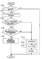
- FIG. 2 is a flowchart of a routine executed by the ECU 50 in the control device for the supercharged internal combustion engine according to the embodiment of the present invention. 2 is executed during the operation of the internal combustion engine 10.
- the waste gate valve is simply expressed as “WGV”.
- step S100 the ECU 50 executes determination processing for determining whether or not the eco-run mode condition is satisfied. If the establishment of this step condition is not confirmed, the current routine is terminated. When the condition of step S100 is satisfied (Yes), the ECU 50 starts the operation of the internal combustion engine 10 in the eco-run mode by the eco-run system.
- step S102 When the automatic stop condition is satisfied when the operation in the eco-run mode is performed due to the satisfaction of the condition of step S100, the ECU 50 executes a process for fuel cut and engine stop control (step S102).
- the ECU 50 executes a determination process for determining whether or not there is a driver's accelerator reacceleration request before the engine is completely stopped (step S104).
- the ECU 50 detects the driver's accelerator operation based on the output of the accelerator position sensor 54, and executes a process for detecting whether or not a reacceleration request has been made. Thereby, the occurrence of COM can be detected.
- step S106 the ECU 50 next executes a process of determining whether or not the engine speed is equal to or higher than the self-recovery return speed at the current engine water temperature (step S106).
- the self-recovery return rotational speed is appropriately defined as a constant, a map, a mathematical expression, or the like by conducting an experiment or the like in advance, and is stored in a memory such as a RAM or ROM of the ECU 50 so that it can be referred to.
- These maps and mathematical expressions define the relationship between the engine water temperature and the self-recovery return rotational speed.
- Such a map or mathematical expression is “information defining the value of the self-recovery return speed corresponding to the engine water temperature of the internal combustion engine”, and is also referred to as “self-sustained return speed characteristic”.
- the map is stored as a self-recovery return speed characteristic.
- step S106 in accordance with the engine water temperature detected based on the output value of the engine water temperature sensor or the like, the self-sustained rotation speed at the current engine water temperature is read from this map.
- the read self-recovery return rotational speed is used for comparison with the current engine rotational speed in the determination process of step S106.
- This self-recovery rotation speed may be calculated in a model manner from the compression ratio, cam timing, and the like.
- step S106 the self-recovery return rotational speed can be adjusted according to the engine water temperature of the internal combustion engine 10. Therefore, it is possible to accurately determine whether or not the self-recovery can be performed from the viewpoint of the engine water temperature, and it is possible to secure an opportunity to perform the control for self-returning the internal combustion engine 10.
- step S106 the ECU 50 next executes a process of opening the waste gate valve 19 (step S108). Thereby, the pumping loss can be reduced. Further, the fuel injection and ignition by the fuel injection valve 28 are restarted, and the control for independently returning the rotation is executed. Thereby, it is possible to immediately respond to the reacceleration request in step S104. Thereafter, the current routine ends.
- step S104 If the condition in step S104 is not satisfied (No), the ECU 50 executes a process of closing the waste gate valve 19 (completely closing it) (step S110). Thereby, a pumping loss can be increased and an engine stop time can be shortened.
- step S112 the ECU 50 executes a process for performing the engine stop control already started in step S102 (step S112).
- step S114 the ECU 50 next executes a process of opening the wastegate valve 19 (step S114).
- step S114 the current routine ends.
- the ECU 50 restarts the internal combustion engine 10 as in the restart in the eco-run system.
- the ECU 50 controls the motor 50 such as a starter motor (not shown) by supplying power from the battery by the control processing. Cranking of the internal combustion engine 10 is performed.
- step S104 When the engine speed reaches a predetermined value due to cranking, fuel injection control and ignition timing control are executed by the ECU 50 based on the crank position, cam position, etc., and the internal combustion engine 10 is driven to the operating state. Is done.
- the opening control of the waste gate valve 19 in the process of step S114 the pumping loss can be reduced in the restart control of the internal combustion engine 10.
- the restartability can be improved and the starting time can be shortened. Thereby, it is possible to respond to the reacceleration request in step S104 as early as possible.
- the turbocharger including the compressor 60 and the turbine 62 is added to the “supercharger” in the first invention in the processing of steps S100 and S102 of the above-described eco-run system and the routine of FIG. Is equivalent to the “operation control means” in the first invention.
- the ECU 50 executes the process of step S104, whereby it is determined whether or not there has been an “operation restart request” in the first aspect of the invention, and the ECU 50 performs step S106.
- the “return control means” in the first invention is changed to the “stop control means” in the first invention by the ECU 50 executing the processing of steps S106 and S110.
- the “restart control means” in the second aspect of the present invention is realized by the ECU 50 executing the process of step S114.
- the “map defining the relationship between the engine water temperature and the self-recovery return speed” stored in the memory in the ECU 50 is the “self-recovery return speed characteristic” in the fourth invention.
- the engine water temperature sensor 58 of the internal combustion engine 10 corresponds to the detection means in the fourth invention.
- the “acquiring means” in the fourth aspect of the present invention is realized by the ECU 50 executing the process of step S106.
- step S106 a routine for shifting to step S106 after performing the process of step S104 once is described.
- the present invention is not limited to this.
- the determination process for determining whether or not an accelerator reacceleration request has been made at a predetermined cycle For example, the following may be performed. First, as long as the condition of the process of step S106 is satisfied (Yes), the process of step S104 and the process of step S106 are repeatedly executed in parallel.
- step S104 If the processing condition of step S104 is satisfied while the processing condition of step S106 is satisfied (Yes), the process proceeds to step S108. On the other hand, when the condition for the process in step S106 is not satisfied (No), the process in step S104 is stopped and the process proceeds to the processes after step S110. As a result, it is possible to secure an opportunity to perform control for allowing the internal combustion engine 10 to return to its own position when the self-recovery is possible.
- the internal combustion engine to which the present invention is applied is not limited to the in-line four-cylinder gasoline engine according to the above-described embodiment, but can be applied to an internal combustion engine with a supercharger having various numbers of cylinders and systems. Further, it may be an internal combustion engine that does not include an external EGR system. Further, in the embodiment, the fuel injection valve 28 is the in-cylinder direct injection injector. However, as a modification, a port injection injector may be used, or the in-cylinder direct injection injector and the port injection injector may be provided. Good.
Abstract
Description
前記ウェストゲートバルブの開閉を制御するウェストゲートバルブ制御手段と、
前記内燃機関の運転中において所定条件が成立したときに前記内燃機関の自動停止を行う自動停止制御を実行可能な運転制御手段と、
前記自動停止制御による停止の途中に前記内燃機関の運転再開要求があった場合に、燃料噴射制御の再開により運転に復帰可能な回転数である自立復帰回転数に前記内燃機関のエンジン回転数が該当するときには、前記内燃機関のポンピングロスが小さくなるように前記ウェストゲートバルブを開き側に制御する復帰制御手段と、
前記自動停止制御による停止の途中に前記内燃機関の運転再開要求があった場合に、前記内燃機関のエンジン回転数が前記自立復帰回転数よりも低いときには、前記内燃機関のポンピングロスが増加するように前記ウェストゲートバルブを閉じ側に制御する停止制御手段と、
を備えることを特徴とする。
前記内燃機関の停止が実現されたときに、前記内燃機関の再始動の前に、前記停止制御手段により閉じ側に制御されたウェストゲートバルブを開き側に制御する再始動制御手段を、
更に備えることを特徴とする。
前記ウェストゲートバルブが、自身の開閉駆動のためのアクチュエータを有しており、
前記復帰制御手段が、前記アクチュエータを制御することによって前記ウェストゲートバルブを全開にするものであり、
前記復帰制御手段が、前記アクチュエータを制御することによって前記ウェストゲートバルブを全閉にするものである、
ことを特徴とする。
前記内燃機関のエンジン水温に応じた前記自立復帰回転数の値を定めた情報である自立復帰回転数特性を記憶した記憶手段と、
前記内燃機関のエンジン水温を検知する検知手段と、
前記記憶手段で記憶した前記自立復帰回転数特性に従って、前記検知手段で検知した前記エンジン水温に基づいて、前記復帰制御手段または/および前記停止制御手段で使用すべき自立復帰回転数を取得する取得手段と、
を更に備えることを特徴とする。
前記復帰制御手段は、
前記内燃機関のエンジン回転数と前記自立復帰回転数とを比較する回転数判定手段と、
前記内燃機関の運転再開要求があるか否かを判定する要求判定手段と、
前記回転数判定手段で前記内燃機関エンジン回転数が前記自立復帰回転数を下回るとの結果が得られるまでは、前記要求判定手段に前記運転再開要求があるか否かの判定を実行させる判定実行手段と、
を含むことを特徴とする。
[実施の形態の構成]
(実施の形態にかかる内燃機関の基本構成)
図1は、本発明の実施の形態にかかる過給機付内燃機関の制御装置の構成を示す図であり、実施の形態にかかる過給機付内燃機関の制御装置が適用される過給機付の内燃機関10の構成を示している。実施の形態においては、内燃機関10は、過給機としてターボチャージャを備えており、車両等の移動体の動力を発生させるための内燃機関として好適に用いられる。このターボチャージャは、吸気通路に配置されたコンプレッサ60、および排気通路に配置されたタービン62を備えている。
本実施形態にかかるターボチャージャは、ウェストゲートバルブ19を備えている。ウェストゲートバルブ19は、ターボチャージャの過給圧を調節する機能を担う。ウェストゲートバルブ19は、開弁圧が予め決定されているタイプのウェストゲートバルブではなく、任意のタイミングで開弁と閉弁とを切り換えることができるウェストゲートバルブとする。具体的には、ウェストゲートバルブ19は、電動式のバルブあるいはバキュームポンプによる負圧調整式のバルブなどの、開閉駆動が可能な外部のアクチュエータを有するバルブ機構である。
ECU50は、上記の各種センサの出力値に基づいて、エンジン回転数やエアフロー、アクセルペダル操作量、排ガスセンサの検出値等を検出する。そして、ECU50は、燃料噴射量、点火タイミング制御、空燃比等を制御する公知のエンジン制御を行うためのエンジン制御部としての役割を担う。ECU50は、ウェストゲートバルブ19と接続し、過給圧制御等の必要に応じてウェストゲートバルブ19の開閉を切り換える制御信号を発する。
ECU50は、内燃機関10の運転をエコランモードで行うためのエコラン制御部を含んでいる。エコラン制御部は、内燃機関10上においてエコランシステムを実施するための制御プログラムを記憶している。
すなわち、車両が停止すると内燃機関を自動停止するエコノミーランニング(「エコラン」とも称す)や自動アイドリングストップ(以下、単に「エコランシステム」とも称す)が知られている。車両が信号待ち等で車速がゼロになると内燃機関を自動停止することで、燃料消費を低減し燃費改善やCO2排出削減といった各種の効果が期待できる。エコランシステムでは、予め定めた自動停止条件(エコランモード条件)を満たす場合に、エンジンを自動停止する。このエコランモード条件には、例えば、アクセルペダルの踏み込み有無、バッテリ残量、ブレーキペダルの踏み込み有無、冷却水温等について定めた所定条件を満たしているかどうかの条件を設定することができる。
実施の形態においては、ECU50がこういったエコランシステムに係る制御プログラムを記憶しており、この制御プログラムに従って、所定のエコランモード条件の成立時に内燃機関の自動停止制御を実行することができる。
まず、自動停止条件の判定は、例えば、車速がゼロになったこと、ブレーキペダルが踏み込まれていること、アクセルペダルが踏み込まれていないこと、水温が所定範囲に入ること、バッテリ残量が基準充電量以上であること、エコラン許可信号が発せられていること、等の各種の条件が成立したか否かを判定することにより行うことができる。本実施形態では、これらのうちいくつかの条件或いは全ての条件を選んだうえで、自動停止条件を予め設定しておくものとする。ECU50は、この自動停止条件が満たされているか否かを判定する判定処理を実行することができる。
また、再始動条件は、例えば、上記の自動停止条件のうち1つでも満たされなくなったか否を条件とすることができる。なお、ECU50には、自動停止条件及び再始動条件を判定するために、車速センサが検出した車速情報、ブレーキペダルストロークセンサの検出信号、アクセルポジションセンサ54が検出したアクセル開度情報、水温センサが検出した水温情報、等も入力されている。
一方、内燃機関10についての自動停止完了後や自動停止処理途中において、再始動条件が成立すると、ECU50は内燃機関10を再始動する。具体的には、再始動条件の成立が認められた場合には、ECU50の制御処理により、バッテリから電力を供給して図示しないスタータモータ等のモータを回転駆動することで内燃機関10のクランキングが行われる。クランキングによりエンジン回転数が所定値に到達した場合には、ECU50の制御処理により、クランクポジションやカムポジション等に基づき、燃料噴射制御や点火タイミング制御が実行されて内燃機関10が運転状態に駆動される。
上述したエコランシステムによれば、所定条件成立時に内燃機関10を自動停止することで、燃料消費を低減し燃費改善やCO2排出削減といった各種の効果が期待できる。しかしながら、内燃機関10の自動停止制御の実行途中に、内燃機関の運転を再開したいという要求(運転再開要求)が発生することがある。そのような運転再開要求として、具体的には、エコランでの課題の一つであるCOM(Change of mind)がある。COMとは、内燃機関を停止しようとしたときに、ドライバがアクセル開度を大きくし、再度の加速を要求することである。
内燃機関を停止しようとしているときに上記のCOMが発生した場合に、復帰・再度の加速が可能かどうかの結論は、その停止制御の中でどの程度までエンジン回転数が低下しているかに応じて決まる。例えば、アイドル回転数が600rpm程度の場合、200rpmから600rpm程度の範囲のエンジン回転数では、停止制御中に燃料噴射を再開することによって、燃料噴射および点火のみによって(つまりモータ等の他の補助動力を必要とせずに)、内燃機関の運転の復帰が可能である。しかしながら、ある程度のエンジン回転数以下になると、エンジンフリクションに対して、筒内燃焼でのエンジントルクが劣ってしまう。そうすると、内燃機関の運転再開のために、エンジン停止を一旦経てからスタータのアシストが必要となってしまう。この場合、ドライバが再度の加速を要求してから、実際に内燃機関が始動して加速へと至るまでの時間が不可避的に生じてしまう。その結果、加速要求に対してのもたつきが生じてしまう。
本実施形態において、この所定回転数には、「自立復帰回転数」が設定される。この「自立復帰回転数」とは、燃料噴射制御の再開により運転に復帰可能な回転数を意味している。より具体的には、実施の形態において、自立復帰回転数とは、「エコランシステムによる自動停止制御が開始された後、その自動停止制御による停止の途中に燃料噴射弁28による燃料噴射および点火タイミング制御を再開することによって、燃料噴射および点火のみによって(つまりモータ等の他の補助動力を必要とせずに)、内燃機関10の運転の復帰が可能である回転数」を意味している。さらに、実施の形態では、この自立復帰回転数は、エンジン水温に応じて異なる回転数に設定され、ECU50にマップ等として記憶されている。そして、上記のエンジン回転数との比較判定を行う際に、エンジン水温に応じた自立復帰回転数の値がマップ等から特定される。
ウェストゲートバルブ19を全開とすることで、ポンピングロスを可能な限り小さくすることができる。その結果、自立復帰を容易化することができる。
ウェストゲートバルブ19を全閉にすることで、ターボチャージャのタービン62側へと空気を送り、ポンピングロスを増加させることができる。これにより、内燃機関10のエンジン停止を容易化し、エンジン停止までの時間を短縮化することができる。その結果、もたつきを抑制することができる。
実施の形態においては、内燃機関10の再始動時に備えて、ウェストゲートバルブ19を開いた状態に戻す。これにより、再始動時にはポンピングロスを低減することができる。
図2は、本発明の実施の形態にかかる過給機付内燃機関の制御装置においてECU50が実行するルーチンのフローチャートである。なお、図2のルーチンは内燃機関10の運転中に実行され、図2においてはウェストゲートバルブを「WGV」と簡略に表記している。
自立復帰回転数は、予め実験等を行うことによって、定数として、或いは、マップや数式などとして適宜に定義し、ECU50のRAMあるいはROMなどのメモリ内に参照可能に記憶しておく。このマップや数式は、エンジン水温と自立復帰回転数との関係を定めたものである。このようなマップや数式は、「内燃機関のエンジン水温に応じた自立復帰回転数の値を定めた情報」であり、これを「自立復帰回転数特性」とも称す。なお、本実施の形態では、マップを、自立復帰回転数特性として記憶しておくものとする。ステップS106において、エンジン水温センサの出力値等に基づいて検知したエンジン水温に応じて、このマップから、現在のエンジン水温での自立復帰回転数を読み出す。読み出された自立復帰回転数は、ステップS106の判定処理において、現在のエンジン回転数との比較に用いられる。この自立復帰回転数は、圧縮比やカムタイミングなどからモデル的に算出してもよい。
ステップS106によれば、内燃機関10のエンジン水温に応じて、自立復帰回転数を調節することができる。従って、エンジン水温の観点から自立復帰が可能かどうかを正確に判定することができ、内燃機関10を自立復帰させる制御を行う機会を確保することができる。
ステップS114の処理におけるウェストゲートバルブ19の開き制御を実行することにより、内燃機関10の再始動制御において、ポンピングロスを低減することができる。その結果、再始動性を向上させることができ、始動時間を短縮化することができる。これにより、ステップS104での再加速要求に、なるべく早期に応えることができる。
また、上述した実施の形態においては、ECU50が上記ステップS114の処理を実行することにより、前記第2の発明における「再始動制御手段」が実現されている。
また、上述した実施の形態においては、ECU50内のメモリに記憶させた「エンジン水温と自立復帰回転数との関係を定めたマップ」が、前記第4の発明における「自立復帰回転数特性」に、内燃機関10のエンジン水温センサ58が、前記第4の発明における検知手段に、それぞれ相当している。また、上述した実施の形態においては、ECU50が上記ステップS106の処理を実行することにより、前記第4の発明における「取得手段」が実現されている。
例えば、次のようにしても良い。先ず、ステップS106の処理の条件が成立(Yes)している限り、ステップS104の処理とステップS106の処理とを並行に繰り返して実行する。ステップS106の処理の条件が成立(Yes)している間にステップS104の処理の条件が成立したら、ステップS108へと進む。一方、ステップS106の処理の条件が不成立(No)となった時点において、ステップS104の処理を止めてステップS110以後の処理へと進む。
これにより、可能な限り、自立復帰が可能であるときに内燃機関10を自立復帰させる制御を行う機会を、確保することができる。
12 シリンダブロック
14 吸気マニホールド
16 排気マニホールド
18 排気管路
19 ウェストゲートバルブ
22 エアフローメータ
24 インタークーラ
26 スロットル
28 燃料噴射弁
36 触媒
40 EGRクーラ
42 EGRバルブ
52 排気ガスセンサ
54 アクセルポジションセンサ
56 クランク角センサ
58 エンジン水温センサ
60 コンプレッサ
62 タービン
Claims (5)
- 過給機と前記過給機のウェストゲートバルブとを備える内燃機関を制御する制御装置であって、
前記ウェストゲートバルブの開閉を制御するウェストゲートバルブ制御手段と、
前記内燃機関の運転中において所定条件が成立したときに前記内燃機関の自動停止を行う自動停止制御を実行可能な運転制御手段と、
前記自動停止制御による停止の途中に前記内燃機関の運転再開要求があった場合に、燃料噴射制御の再開により運転に復帰可能な回転数である自立復帰回転数に前記内燃機関のエンジン回転数が該当するときには、前記内燃機関のポンピングロスが小さくなるように前記ウェストゲートバルブを開き側に制御する復帰制御手段と、
前記自動停止制御による停止の途中に前記内燃機関の運転再開要求があった場合に、前記内燃機関のエンジン回転数が前記自立復帰回転数よりも低いときには、前記内燃機関のポンピングロスが増加するように前記ウェストゲートバルブを閉じ側に制御する停止制御手段と、
を備えることを特徴とする過給機付内燃機関の制御装置。 - 前記内燃機関の停止が実現されたときに、前記内燃機関の再始動の前に、前記停止制御手段により閉じ側に制御されたウェストゲートバルブを開き側に制御する再始動制御手段を、
更に備えることを特徴とする請求項1に記載の過給機付内燃機関の制御装置。 - 前記ウェストゲートバルブが、自身の開閉駆動のためのアクチュエータを有しており、
前記復帰制御手段が、前記アクチュエータを制御することによって前記ウェストゲートバルブを全開にするものであり、
前記復帰制御手段が、前記アクチュエータを制御することによって前記ウェストゲートバルブを全閉にするものである、
ことを特徴とする請求項1または2に記載の過給機付内燃機関の制御装置。 - 前記内燃機関のエンジン水温に応じた前記自立復帰回転数の値を定めた情報である自立復帰回転数特性を記憶した記憶手段と、
前記内燃機関のエンジン水温を検知する検知手段と、
前記記憶手段で記憶した前記自立復帰回転数特性に従って、前記検知手段で検知した前記エンジン水温に基づいて、前記復帰制御手段または/および前記停止制御手段で使用すべき自立復帰回転数を取得する取得手段と、
を更に備えることを特徴とする請求項1乃至3のいずれか1項に記載の過給機付内燃機関の制御装置。 - 前記復帰制御手段は、
前記内燃機関のエンジン回転数と前記自立復帰回転数とを比較する回転数判定手段と、
前記内燃機関の運転再開要求があるか否かを判定する要求判定手段と、
前記回転数判定手段で前記内燃機関エンジン回転数が前記自立復帰回転数を下回るとの結果が得られるまでは、前記要求判定手段に前記運転再開要求があるか否かの判定を実行させる判定実行手段と、
を含むことを特徴とする請求項1乃至4のいずれか1項に記載の過給機付内燃機関の制御装置。
Priority Applications (5)
| Application Number | Priority Date | Filing Date | Title |
|---|---|---|---|
| EP11819040.4A EP2696053B1 (en) | 2011-04-08 | 2011-04-08 | Control device for an internal combustion engine with supercharger |
| US13/504,069 US9097175B2 (en) | 2011-04-08 | 2011-04-08 | Internal combustion engine with supercharger |
| CN201180036608.4A CN103038478B (zh) | 2011-04-08 | 2011-04-08 | 带增压器的内燃机的控制装置 |
| PCT/JP2011/058901 WO2012137345A1 (ja) | 2011-04-08 | 2011-04-08 | 過給機付内燃機関の制御装置 |
| JP2012517595A JP5278609B2 (ja) | 2011-04-08 | 2011-04-08 | 過給機付内燃機関の制御装置 |
Applications Claiming Priority (1)
| Application Number | Priority Date | Filing Date | Title |
|---|---|---|---|
| PCT/JP2011/058901 WO2012137345A1 (ja) | 2011-04-08 | 2011-04-08 | 過給機付内燃機関の制御装置 |
Publications (1)
| Publication Number | Publication Date |
|---|---|
| WO2012137345A1 true WO2012137345A1 (ja) | 2012-10-11 |
Family
ID=46968780
Family Applications (1)
| Application Number | Title | Priority Date | Filing Date |
|---|---|---|---|
| PCT/JP2011/058901 WO2012137345A1 (ja) | 2011-04-08 | 2011-04-08 | 過給機付内燃機関の制御装置 |
Country Status (5)
| Country | Link |
|---|---|
| US (1) | US9097175B2 (ja) |
| EP (1) | EP2696053B1 (ja) |
| JP (1) | JP5278609B2 (ja) |
| CN (1) | CN103038478B (ja) |
| WO (1) | WO2012137345A1 (ja) |
Cited By (4)
| Publication number | Priority date | Publication date | Assignee | Title |
|---|---|---|---|---|
| JP2016011632A (ja) * | 2014-06-30 | 2016-01-21 | 日産自動車株式会社 | 内燃機関の制御装置 |
| US10234056B2 (en) | 2015-04-06 | 2019-03-19 | Mitsubishi Electric Corporation | Control device for actuator, actuator, valve driving device and abnormality detecting method for actuator |
| US10422274B2 (en) | 2015-04-09 | 2019-09-24 | Mitsubishi Electric Corporation | Control device for actuator, actuator, valve driving device and control method for actuator |
| DE112015006422B4 (de) | 2015-04-06 | 2022-02-17 | Mitsubishi Electric Corporation | Wastegate-Stellantrieb und Wastegate-Ventil-Antriebseinrichtung |
Families Citing this family (13)
| Publication number | Priority date | Publication date | Assignee | Title |
|---|---|---|---|---|
| JP6112299B2 (ja) * | 2013-06-14 | 2017-04-12 | 三菱自動車工業株式会社 | エンジンの制御装置 |
| FR3045107A1 (fr) * | 2015-12-14 | 2017-06-16 | Peugeot Citroen Automobiles Sa | Procede pour minimiser des pertes de pompage dans un moteur thermique lors d'un demarrage |
| CN107327351A (zh) * | 2016-04-28 | 2017-11-07 | 联合汽车电子有限公司 | 三缸发动机熄火控制系统 |
| EP3276787B1 (de) | 2016-07-29 | 2019-01-02 | Ford Global Technologies, LLC | Elektrisches bordnetzsystem für kraftfahrzeuge mit einem konverter und einem hochlastverbraucher |
| EP3276768B1 (de) | 2016-07-29 | 2019-04-24 | Ford Global Technologies, LLC | Elektrisches bordnetzsystem für kraftfahrzeuge mit einem konverter und einem hochlastverbraucher |
| US10451022B2 (en) | 2016-11-02 | 2019-10-22 | Paccar Inc | Intermittent restart for automatic engine stop start system |
| US9957941B1 (en) * | 2016-11-02 | 2018-05-01 | Paccar Inc | Intermittent restart for automatic engine stop start system |
| DE102017216380A1 (de) * | 2017-09-15 | 2019-03-21 | Robert Bosch Gmbh | Verfahren zur Steuerung eines mindestens teilweise elektrisch betreibbaren Laders für ein Kraftfahrzeug mit einer Verbrennungskraftmaschine |
| US10690103B2 (en) | 2017-09-26 | 2020-06-23 | Paccar Inc | Systems and methods for using an electric motor in predictive and automatic engine stop-start systems |
| US10487762B2 (en) | 2017-09-26 | 2019-11-26 | Paccar Inc | Systems and methods for predictive and automatic engine stop-start control |
| US10883566B2 (en) | 2018-05-09 | 2021-01-05 | Paccar Inc | Systems and methods for reducing noise, vibration and/or harshness associated with cylinder deactivation in internal combustion engines |
| US10746255B2 (en) | 2018-05-09 | 2020-08-18 | Paccar Inc | Systems and methods for reducing noise, vibration, and/or harshness during engine shutdown and restart |
| US11629659B2 (en) * | 2021-06-14 | 2023-04-18 | Ford Global Technologies, Llc | Methods and system to shutdown an engine |
Citations (5)
| Publication number | Priority date | Publication date | Assignee | Title |
|---|---|---|---|---|
| JP2003065104A (ja) | 2001-08-29 | 2003-03-05 | Toyota Motor Corp | 内燃機関の停止・始動制御装置 |
| JP2006183629A (ja) * | 2004-12-28 | 2006-07-13 | Nissan Motor Co Ltd | 内燃機関及びその制御方法 |
| JP2009174493A (ja) * | 2008-01-28 | 2009-08-06 | Mazda Motor Corp | ディーゼルエンジンの過給装置 |
| JP2009197738A (ja) | 2008-02-22 | 2009-09-03 | Mazda Motor Corp | エンジンの自動停止装置 |
| JP2010127213A (ja) * | 2008-11-28 | 2010-06-10 | Nissan Motor Co Ltd | エンジンの吸気制御装置及び吸気制御方法 |
Family Cites Families (16)
| Publication number | Priority date | Publication date | Assignee | Title |
|---|---|---|---|---|
| JPS60252123A (ja) * | 1984-05-30 | 1985-12-12 | Hino Motors Ltd | ウエストゲ−トの制御装置 |
| JP2634083B2 (ja) * | 1989-07-27 | 1997-07-23 | ダイハツ工業株式会社 | エンジンの大気圧補正方法 |
| US5622053A (en) * | 1994-09-30 | 1997-04-22 | Cooper Cameron Corporation | Turbocharged natural gas engine control system |
| EP0824186B1 (en) * | 1996-08-09 | 2001-11-21 | Mitsubishi Jidosha Kogyo Kabushiki Kaisha | Control system for internal combustion engine |
| JPH11278091A (ja) * | 1998-03-30 | 1999-10-12 | Toyota Motor Corp | エンジン始動装置 |
| JP3451931B2 (ja) * | 1998-05-20 | 2003-09-29 | トヨタ自動車株式会社 | 車両のエンジン停止制御装置 |
| EP0990793B1 (en) * | 1998-09-28 | 2004-08-25 | Toyota Jidosha Kabushiki Kaisha | Stop and restart device for vehicular engine |
| JP2000110597A (ja) * | 1998-10-05 | 2000-04-18 | Mitsubishi Motors Corp | エンジンの自動停止・再始動装置 |
| JP2001055941A (ja) * | 1999-08-16 | 2001-02-27 | Honda Motor Co Ltd | エンジン自動始動停止制御装置 |
| US6363906B1 (en) * | 2000-03-06 | 2002-04-02 | Detroit Diesel Corporation | Idle shutdown override with defeat protection |
| JP3633531B2 (ja) * | 2001-08-28 | 2005-03-30 | トヨタ自動車株式会社 | 内燃機関の停止・始動制御装置 |
| DE102006043678B4 (de) * | 2006-09-18 | 2017-11-30 | Robert Bosch Gmbh | Vorrichtung und Verfahren zum Betreiben einer Brennkraftmaschine |
| DE102008005525A1 (de) * | 2008-01-22 | 2009-07-23 | Robert Bosch Gmbh | Verfahren zum Start einer Brennkraftmaschine mit Start-Stopp-Funktion |
| US8112208B2 (en) * | 2009-05-28 | 2012-02-07 | Ford Global Technologies, Llc | Engine speed reduction preparatory to an engine restart |
| US8795135B2 (en) * | 2009-09-01 | 2014-08-05 | Ford Global Technologies, Llc | Method for controlling an engine during a restart |
| JP5370243B2 (ja) * | 2010-03-31 | 2013-12-18 | マツダ株式会社 | ターボ過給機付きディーゼルエンジンの制御装置 |
-
2011
- 2011-04-08 EP EP11819040.4A patent/EP2696053B1/en active Active
- 2011-04-08 CN CN201180036608.4A patent/CN103038478B/zh not_active Expired - Fee Related
- 2011-04-08 WO PCT/JP2011/058901 patent/WO2012137345A1/ja active Application Filing
- 2011-04-08 US US13/504,069 patent/US9097175B2/en active Active
- 2011-04-08 JP JP2012517595A patent/JP5278609B2/ja active Active
Patent Citations (5)
| Publication number | Priority date | Publication date | Assignee | Title |
|---|---|---|---|---|
| JP2003065104A (ja) | 2001-08-29 | 2003-03-05 | Toyota Motor Corp | 内燃機関の停止・始動制御装置 |
| JP2006183629A (ja) * | 2004-12-28 | 2006-07-13 | Nissan Motor Co Ltd | 内燃機関及びその制御方法 |
| JP2009174493A (ja) * | 2008-01-28 | 2009-08-06 | Mazda Motor Corp | ディーゼルエンジンの過給装置 |
| JP2009197738A (ja) | 2008-02-22 | 2009-09-03 | Mazda Motor Corp | エンジンの自動停止装置 |
| JP2010127213A (ja) * | 2008-11-28 | 2010-06-10 | Nissan Motor Co Ltd | エンジンの吸気制御装置及び吸気制御方法 |
Non-Patent Citations (1)
| Title |
|---|
| See also references of EP2696053A4 |
Cited By (5)
| Publication number | Priority date | Publication date | Assignee | Title |
|---|---|---|---|---|
| JP2016011632A (ja) * | 2014-06-30 | 2016-01-21 | 日産自動車株式会社 | 内燃機関の制御装置 |
| US10234056B2 (en) | 2015-04-06 | 2019-03-19 | Mitsubishi Electric Corporation | Control device for actuator, actuator, valve driving device and abnormality detecting method for actuator |
| DE112015006422B4 (de) | 2015-04-06 | 2022-02-17 | Mitsubishi Electric Corporation | Wastegate-Stellantrieb und Wastegate-Ventil-Antriebseinrichtung |
| DE112015006420B4 (de) | 2015-04-06 | 2023-03-23 | Mitsubishi Electric Corporation | Steuervorrichtung für Aktor, Aktor, Ventiltreibervorrichtung und Abnormalitätserfassungsverfahren für Aktor |
| US10422274B2 (en) | 2015-04-09 | 2019-09-24 | Mitsubishi Electric Corporation | Control device for actuator, actuator, valve driving device and control method for actuator |
Also Published As
| Publication number | Publication date |
|---|---|
| EP2696053A1 (en) | 2014-02-12 |
| EP2696053B1 (en) | 2018-01-17 |
| JPWO2012137345A1 (ja) | 2014-07-28 |
| EP2696053A4 (en) | 2014-12-17 |
| JP5278609B2 (ja) | 2013-09-04 |
| US20140026559A1 (en) | 2014-01-30 |
| CN103038478A (zh) | 2013-04-10 |
| US9097175B2 (en) | 2015-08-04 |
| CN103038478B (zh) | 2015-01-07 |
Similar Documents
| Publication | Publication Date | Title |
|---|---|---|
| JP5278609B2 (ja) | 過給機付内燃機関の制御装置 | |
| US8109092B2 (en) | Methods and systems for engine control | |
| US8978378B2 (en) | Method and system for reducing turbocharger noise during cold start | |
| US8439002B2 (en) | Methods and systems for engine control | |
| JP6322618B2 (ja) | 内燃機関の制御装置 | |
| JP6132092B2 (ja) | エンジンの制御装置 | |
| JP3731025B2 (ja) | 内燃機関の空気量制御装置 | |
| JP6661593B2 (ja) | 内燃機関の制御装置 | |
| US8464529B2 (en) | Reduction in turbocharger lag at high altitudes | |
| JP2013155615A (ja) | 内燃機関の制御装置 | |
| EP0926328B1 (en) | Control system for internal combustion engine | |
| JP2004027914A (ja) | 内燃機関の制御装置 | |
| JP5081117B2 (ja) | 過給機付エンジンの制御装置 | |
| JP2005120905A (ja) | 多気筒内燃機関の始動制御方法 | |
| JP6160816B2 (ja) | エンジンの制御装置 | |
| JP2000145524A (ja) | 可変ターボチャージャを備えた内燃機関 | |
| JP2006017053A (ja) | 過給機付き内燃機関の燃料噴射時期制御装置 | |
| JP4020582B2 (ja) | 内燃機関の制御装置 | |
| JP4946782B2 (ja) | 内燃機関の制御装置 | |
| WO2013168247A1 (ja) | 過給機付き内燃機関の制御装置 | |
| JP3289653B2 (ja) | 内燃機関の制御装置 | |
| JP5574922B2 (ja) | 内燃機関 | |
| JP6154232B2 (ja) | 過給機付きエンジンの制御装置 | |
| JP4022848B2 (ja) | 内燃機関の燃料噴射制御装置 | |
| JP2010180752A (ja) | 筒内噴射型内燃機関 |
Legal Events
| Date | Code | Title | Description |
|---|---|---|---|
| WWE | Wipo information: entry into national phase |
Ref document number: 201180036608.4 Country of ref document: CN |
|
| WWE | Wipo information: entry into national phase |
Ref document number: 2011819040 Country of ref document: EP |
|
| ENP | Entry into the national phase |
Ref document number: 2012517595 Country of ref document: JP Kind code of ref document: A |
|
| WWE | Wipo information: entry into national phase |
Ref document number: 13504069 Country of ref document: US |
|
| 121 | Ep: the epo has been informed by wipo that ep was designated in this application |
Ref document number: 11819040 Country of ref document: EP Kind code of ref document: A1 |
|
| NENP | Non-entry into the national phase |
Ref country code: DE |