WO2012133682A1 - マスタシリンダ - Google Patents
マスタシリンダ Download PDFInfo
- Publication number
- WO2012133682A1 WO2012133682A1 PCT/JP2012/058426 JP2012058426W WO2012133682A1 WO 2012133682 A1 WO2012133682 A1 WO 2012133682A1 JP 2012058426 W JP2012058426 W JP 2012058426W WO 2012133682 A1 WO2012133682 A1 WO 2012133682A1
- Authority
- WO
- WIPO (PCT)
- Prior art keywords
- piston
- lip
- cylinder body
- lower side
- inner lip
- Prior art date
- Legal status (The legal status is an assumption and is not a legal conclusion. Google has not performed a legal analysis and makes no representation as to the accuracy of the status listed.)
- Ceased
Links
Images


Classifications
-
- F—MECHANICAL ENGINEERING; LIGHTING; HEATING; WEAPONS; BLASTING
- F16—ENGINEERING ELEMENTS AND UNITS; GENERAL MEASURES FOR PRODUCING AND MAINTAINING EFFECTIVE FUNCTIONING OF MACHINES OR INSTALLATIONS; THERMAL INSULATION IN GENERAL
- F16J—PISTONS; CYLINDERS; SEALINGS
- F16J15/00—Sealings
- F16J15/16—Sealings between relatively-moving surfaces
- F16J15/32—Sealings between relatively-moving surfaces with elastic sealings, e.g. O-rings
- F16J15/3204—Sealings between relatively-moving surfaces with elastic sealings, e.g. O-rings with at least one lip
- F16J15/3232—Sealings between relatively-moving surfaces with elastic sealings, e.g. O-rings with at least one lip having two or more lips
- F16J15/3236—Sealings between relatively-moving surfaces with elastic sealings, e.g. O-rings with at least one lip having two or more lips with at least one lip for each surface, e.g. U-cup packings
-
- B—PERFORMING OPERATIONS; TRANSPORTING
- B60—VEHICLES IN GENERAL
- B60T—VEHICLE BRAKE CONTROL SYSTEMS OR PARTS THEREOF; BRAKE CONTROL SYSTEMS OR PARTS THEREOF, IN GENERAL; ARRANGEMENT OF BRAKING ELEMENTS ON VEHICLES IN GENERAL; PORTABLE DEVICES FOR PREVENTING UNWANTED MOVEMENT OF VEHICLES; VEHICLE MODIFICATIONS TO FACILITATE COOLING OF BRAKES
- B60T11/00—Transmitting braking action from initiating means to ultimate brake actuator without power assistance or drive or where such assistance or drive is irrelevant
- B60T11/10—Transmitting braking action from initiating means to ultimate brake actuator without power assistance or drive or where such assistance or drive is irrelevant transmitting by fluid means, e.g. hydraulic
- B60T11/16—Master control, e.g. master cylinders
- B60T11/236—Piston sealing arrangements
Definitions
- the present invention relates to a master cylinder of a braking device, in particular, a master provided with a cylinder body, a piston inserted through the cylinder body, and an annular seal member provided on the outer periphery of the piston and blocking the inside of the cylinder body from outside air.
- a master provided with a cylinder body, a piston inserted through the cylinder body, and an annular seal member provided on the outer periphery of the piston and blocking the inside of the cylinder body from outside air.
- a pressure chamber composed of a cylinder body and a piston communicates with a reservoir for storing brake fluid.
- the seal member provided on the outer periphery of the piston is in sliding contact with the outer periphery of the piston and has a sealing property to block the cylinder body from the outside air.
- a bush member is fitted to the large diameter portion side of a stepped cylinder hole having a small diameter portion and a large diameter portion.
- the bush member supports a plunger that is slidably inserted into the cylinder hole.
- a cup seal is disposed between the bush member and the step of the cylinder hole so as to be movable in the axial direction of the cylinder hole.
- the inner peripheral lip portion of the cup seal is in close contact with the outer periphery of the plunger.
- a recess is provided in the outer peripheral portion of the bush member on the cup seal side.
- the cup seal is provided with a protrusion that slidably engages with the recess. This protrusion is formed in such a length that the protrusion does not fall out of the recess even when the cup seal moves away from the bush member and contacts the stepped portion (see Patent Document 1).
- a cylindrical connecting member is interposed between the outer peripheral surface of the piston and the cylindrical portion of the valve guide.
- a cup seal guide for preventing the cup seal from being turned up is integrally provided on a connecting member (see Patent Document 2).
- the cup seal is prevented from being turned over (reversed) by a cup seal guide provided on the connecting member.
- the present invention has been made in view of the above problems, and an object of the present invention is to provide a master cylinder that prevents reversal of a seal member that seals a cylinder body with a simple structure.
- a master cylinder of the present invention includes a cylinder main body, a groove provided on the inner peripheral surface of the cylinder main body over the entire circumference, and inserted into the cylinder main body.
- a piston that is pressed in the axial direction of the cylinder body, and an annular seal member that is provided on the outer periphery of the piston while being accommodated in the groove, and that shields the inside of the cylinder body from outside air.
- the member includes an inner lip that is in sliding contact with the piston, and an outer lip that is provided on the radially outer side than the inner lip, and that is connected on the upper side in the pressing direction of the piston.
- a projecting portion that projects toward the lower side in the pressing direction is formed over the entire circumference of the end surface on the lower side in the pressing direction of the piston, Out portion is provided with a tip that protrudes most in the pressing direction downstream side at a position on the inner diameter side than the radial center or near the radial center of the inner lip.
- tip part is formed in the edge part of the inner side lip of the seal member of the side which moves when a piston is pressed. For this reason, when the inner lip is deformed by the frictional force, the tip portion comes into contact with the inner wall surface of the groove portion. At this time, stress from the inner wall surface acts on the tip portion. The more the radial position of the tip is radially outward, the greater the rotational moment acting on the seal member and the easier it is for the seal member to reverse.
- the radial position of the tip portion is set to the inner diameter side of the radial center of the inner lip.
- the radial position of the tip portion is set near the radial center of the inner lip.
- the inner wall surface on the lower side in the pressing direction of the groove has an inclined surface that is inclined toward the lower side in the pressing direction toward the radially inner side.
- the inner wall surface of the groove portion with which the tip end abuts is inclined toward the lower side in the pressing direction toward the radially inner side. For this reason, when stress acts on the tip portion, it tends to act radially inward, and the reversal of the seal member can be prevented.
- the inner lip is formed with a constricted portion between a sliding contact portion of the inner lip with the piston and the protruding portion.
- the radially inner part of the protrusion is constricted.
- the volume of the radially outer portion of the protrusion is larger than the volume of the inner portion, and the rigidity of the radially outer portion is increased. Therefore, when the tip of the projecting portion comes into contact with the inner wall surface of the groove due to the pushing of the piston, the inner lip is likely to act radially inward, and the reversal of the seal member can be prevented.
- FIG. 1 is a cross-sectional view of the master cylinder in a state where the braking device is not operating (hereinafter referred to as an initial state). Note that the master cylinder of the present embodiment is configured in a tandem type.
- a first piston 21 (a piston of the present invention) and a second piston 23 are provided inside the cylinder body 11.
- One end (left side in the figure) of the first piston 21 is inserted into the cylinder body 11, and the other end (right side in the figure) protrudes outside the cylinder body 11.
- a braking operation member (not shown) that applies a pressing force in the left direction in the drawing to the first piston 21 according to the operation of the brake pedal is connected to the protruding end side of the first piston 21. ing. Therefore, in the following description, the right side in the drawing is expressed as an upper hand and the left side is expressed as a lower hand, based on the pressing direction. On the other hand, the entire second piston 23 is inserted into the cylinder body 11.
- the space surrounded by the cylinder body 11, the first piston 21, and the second piston 23 constitutes the first pressure chamber 55.
- a space surrounded by the cylinder body 11 and the second piston 23 constitutes a second pressure chamber 57. Therefore, when the brake pedal is operated and the first piston 21 is pressed, the first pressure chamber 55 and the second pressure chamber 57 are compressed and pressurized.
- a return spring 75 is provided in the first pressure chamber 55, and a return spring 77 is provided in the second pressure chamber 57.
- the return springs 75 and 77 urge the first piston 21 and the second piston 23 in the upward direction, respectively.
- the first pressure chamber 55 communicates with a reservoir (not shown) through a communication passage 51 formed in the cylinder body 11.
- the second pressure chamber 57 communicates with the reservoir via a communication passage 53 formed in the cylinder body 11.
- the first piston 21 and the second piston 23 are formed with a first piston port 25 and a second piston port 27 penetrating in the radial direction, respectively.
- a plurality of first piston ports 25 and second piston ports 27 are formed in the circumferential direction.
- the first piston port 25 is open to the communication passage 51, and the first pressure chamber 55 is in communication with the reservoir.
- the second piston port 27 is open to the communication path 53, the second pressure chamber 57 is in communication with the reservoir.
- the outer periphery of the first piston 21 is provided with an annular primary cup 31 and a secondary cup 33 (sealing member of the present invention) formed of an elastic body such as rubber so as to be in sliding contact with the outer peripheral surface of the first piston 21. Yes.
- the primary cup 31 seals the outer periphery of the first piston 21.
- the secondary cup 33 blocks the inside of the cylinder body 11 from the outside atmosphere at the portion where the first piston 21 is inserted into the cylinder body 11.
- annular primary cup 35 and a pressure cup 37 formed of an elastic body such as rubber are provided on the outer periphery of the second piston 23 so as to be in sliding contact with the outer peripheral surface of the second piston 23.
- the primary cup 35 seals the outer periphery of the second piston 23.
- the pressure cup 37 blocks the first pressure chamber 55 and the communication passage 53 on the outer periphery of the second piston 23.
- the cylinder body 11 is formed with storage grooves 13, 17, 15, 19 (the storage groove 15 is the groove portion of the present invention) for storing the primary cups 31, 35, the secondary cup 33, and the pressure cup 37.
- the storage groove 15 is the groove portion of the present invention
- a groove 63 that connects the storage groove 17 and the second pressure chamber 57 is formed on the lower side of the storage groove 17.
- a groove 65 that connects the storage groove 19 and the first pressure chamber 55 is formed on the upper side of the storage groove 19.
- a plurality of these grooves 61, 63, 65 are formed in the circumferential direction.
- the depression force applies a pressing force in the lower direction to the first piston 21 via the braking operation member.
- the first piston 21 moves in the lower direction.
- the first piston port 25 moves in a lower direction than the primary cup 31 due to the movement of the first piston 21, the communication between the reservoir and the first pressure chamber 55 is blocked. Thereafter, when the first piston 21 moves in the lower direction, the brake fluid in the first pressure chamber 55 is pressurized.
- the second piston 23 also starts moving in the lower direction by the urging force of the return spring 75.
- the second piston port 27 moves in a lower direction than the primary cup 35 due to the movement of the second piston 23, the communication between the reservoir and the second pressure chamber 57 is cut off, and the brake fluid in the second pressure chamber 57 is added. Pressed.
- the braking device can be operated by the pressurized brake fluid in the first pressure chamber 55 and the second pressure chamber 57.
- the secondary cup 33 is provided so as to be in sliding contact with the outer peripheral surface of the first piston 21. Therefore, when the first piston 21 moves, a frictional force acts on the surface of the secondary cup 33 that is in sliding contact with the outer peripheral surface of the first piston 21, and the secondary cup 33 may be dragged in the moving direction of the first piston 21. In this case, the secondary cup 33 is reversed and the sealing performance is lowered. Further, this inversion may cause tearing or the like in the secondary cup 33.
- the secondary cup 33 In the master cylinder of the present invention, in order to prevent the secondary cup 33 from being reversed due to the movement of the first piston 21, the secondary cup 33 having a shape as shown in FIGS.
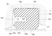
- FIG. 2 and 3 are cross-sectional views of the secondary cup 33 in the present embodiment.
- FIG. 2 shows the shape in the initial state
- FIG. 3 shows the shape when the braking device operates and the first piston 21 moves to the lower side.
- the secondary cup 33 includes an inner lip 33a that is in sliding contact with the first piston 21, and an outer lip 33b that is provided on the outer diameter side of the inner lip 33a.
- the inner lip 33a and the outer lip 33b are connected to each other at the upper end by a connecting portion 33c. Therefore, the cross-sectional shape of the secondary cup 33 is substantially U-shaped.
- a projecting portion 33d projecting to the lower side is formed on the lower end surface of the inner lip 33a over the entire circumference.
- the storage groove 15 for storing the secondary cup 33 is formed over the entire inner peripheral surface of the cylinder body 11 and opens toward the first piston 21 as shown in FIG.
- a radially outer inner wall surface (hereinafter referred to as an upper inner surface 15a) of the storage groove 15 is in contact with a radially outer surface of the outer lip 33b.
- the inner wall surface on the lower side of the storage groove 15 (the inner wall surface of the present invention, hereinafter referred to as the front inner surface 15b) is in contact with the lower end portion of the outer lip 33b.
- a slight clearance is formed between the upper inner wall surface of the storage groove 15 (hereinafter referred to as the rear inner surface 15c) and the connecting portion 33c. With such a configuration, the secondary cup 33 can be positioned in the storage groove 15. As is apparent from FIG. 2, the tip 33e is not in contact with the front inner surface 15b in the initial state.
- the radial position of the distal end portion 33e that projects to the lowermost side of the projecting portion 33d is located radially inward from the vicinity of the radial center of the inner lip 33a or the radial direction of the distal end portion 33e. Is the vicinity of the center in the radial direction of the inner lip 33a.
- the rotational moment since the rotational moment becomes small, the secondary cup 33 can be prevented from being reversed.
- the rotational moment may be larger than in the former case, and in that case, the possibility of reversal of the secondary cup 33 becomes higher than in the former case. In this case, as shown in FIG.
- the front inner surface 15b so as to be inclined toward the lower side toward the radially inner side. Due to this inclination, the stress of the front inner surface 15b acts to press the inner lip 33a against the first piston 21, so that the secondary cup can be prevented from being reversed.
- the inclination angle of the front inner surface 15b is a value that should be determined by the rigidity of the secondary cup 33, the magnitude of the frictional force, and the like, but is set to 7 ° in the present embodiment. Further, the vicinity of the center in the radial direction of the inner lip 33a is, for example, about 1/3 of the thickness of the inner lip 33a with reference to the center in the radial direction of the inner lip 33a.
- the thickness of the inner lip 33a refers to the radially outer surface of the inner lip 33a in the initial state (hereinafter referred to as the outer peripheral surface 33f) and the radially inner surface of the inner lip 33a (hereinafter referred to as the inner peripheral surface 33g). ).
- the radial position of the tip 33e can be determined from another viewpoint.
- the rotational moment increases as the distal end portion 33e is moved outward in the radial direction, and the secondary cup 33 is easily reversed.
- the pressing force applied to the lower end portion of the inner peripheral surface 33g increases, which may hinder the sliding of the first piston 21 and impair the operational feeling of the brake pedal. There is.
- the position of the tip 33e and the inclination angle of the front inner surface 15b are set so that the direction of the reaction force input from the tip 33e passes through the center of gravity of the inner lip 33a in FIG.
- the position of the tip portion 33e is determined in this way, it is difficult to generate a force for rotating the inner lip 33a due to the pressure from the front inner surface 15b, and the secondary cup 33 can be prevented from being reversed.
- the condition for the inner lip 33a to receive a purely uniaxial compressive force is determined only by the center of gravity.
- the optimum condition is appropriately determined based on the rigidity and shape of the inner lip 33a as well as the position of the tip 33e.
- the secondary cup 33 can be prevented from being reversed.
- a constricted portion 33h is formed between the lower end portion of the inner peripheral surface 33g of the inner lip 33a and the tip portion 33e.
- the rigidity of the inner portion is lower than the radially outer portion of the tip portion 33e of the protruding portion 33d. Therefore, when the distal end portion 33e bends, it tends to bend radially inward. In this case, since the force acts in the direction of pressing the inner lip 33a against the outer peripheral surface of the first piston 21, the inversion can be prevented.
- the constricted portion 33h may be formed over the entire circumference of the secondary cup 33, or may be formed discretely on the circumference.
- the front inner surface 15 b of the storage groove 15 is configured to be inclined. However, it may be configured not to be inclined, that is, to be orthogonal to the outer peripheral surface of the first piston 21.
- the present invention can be applied to a master cylinder including a cylinder body, a piston inserted through the cylinder body, and an annular seal member provided on the outer periphery of the piston and blocking the inside of the cylinder body from outside air.
- Cylinder body 15 Storage groove (groove) 15b: Front inner surface (inner wall surface) 21: First piston (piston) 33: Secondary cup (seal member) 33a: inner lip 33b: outer lip 33d: protrusion 33e: tip 33h: constriction
Landscapes
- Engineering & Computer Science (AREA)
- General Engineering & Computer Science (AREA)
- Mechanical Engineering (AREA)
- Transportation (AREA)
- Transmission Of Braking Force In Braking Systems (AREA)
- Sealing With Elastic Sealing Lips (AREA)
Abstract
簡易な構造でシリンダ本体をシールするシール部材の反転を防止するマスタシリンダを提供する。シリンダ本体11の内部を外気から遮断する環状のシール部材33が、シリンダ本体11の内周面の全周にわたって形成された溝部15に収容されている。シール部材33は、ピストン21と摺接する内側リップ33aと、内側リップ33aよりも径方向外側に設けられるとともに、内側リップ33aとピストン21の押圧方向上手側で接続される外側リップ33bと、を備え、内側リップ33aのピストン21の押圧方向下手側の端面の全周にわたって、押圧方向下手側に突出する突出部33dが形成されている。突出部33dは、内側リップ33aの径方向中央近傍または径方向中央よりも内径側の位置において押圧方向下手側に最も突出する先端部33eを備えている。
Description
本発明は、制動装置のマスタシリンダ、特に、シリンダ本体と、シリンダ本体に挿通されるピストンと、ピストンの外周に設けられ、シリンダ本体の内部を外気から遮断する環状のシール部材とを備えたマスタシリンダに関する。
上述のようなマスタシリンダが採用された制動装置では、制動装置の非作動時には、シリンダ本体とピストンとで構成される圧力室と、ブレーキ液を貯蔵するリザーバとが連通している。ピストンの外周に設けられたシール部材は、ピストンの外周と摺接し、シンリンダ本体を外気から遮断するシール性を有している。
ブレーキペダル等を操作して制動力を生じさせる際には、ブレーキペダル等に加えられた踏力等がピストンに伝達され、ピストンが軸芯方向で圧力室の容積を圧縮する方向に移動する。このとき、シール部材のピストンとの摺接面にはピストンの移動に伴う摩擦力が生じる。この摩擦力により、シール部材が反転し、シール性を確保できなくなるおそれがある。
このような問題点を解決するために、例えば従来のマスタシリンダでは、小径部と大径部とを有する段状のシンリンダ孔の大径部側にブッシュ部材を嵌着したものがある。このブッシュ部材は、シリンダ孔に摺動自在に内挿されるプランジャを支持する。ブッシュ部材とシリンダ孔の段部との間には、カップシールを、シリンダ孔の軸方向に移動可能に配置してある。カップシールの内周リップ部はプランジャの外周に密接している。ブッシュ部材のうちカップシール側の外周部には凹部が設けられている。カップシールには、この凹部に摺動可能に係合する突起を設けてある。この突起は、カップシールがブッシュ部材から離れて段部に当接するまで移動したときでも、突起が凹部から脱落しない長さに形成してある(特許文献1参照)。
この特許文献1のマスタシリンダでは、カップシールに形成された突起と、ブッシュ部材に形成された凹部とが係合する。このため、プランジャの移動に際して、カップシールの反転を防止することができる。
また、ピストンの前部側外周にカップシールを嵌着したセンタバルブ型車両用液圧マスタシリンダにおいて、ピストンの先端側外周面とバルブガイドの筒部との間に筒状の連結部材を介装し、連結部材に、カップシールのめくれを防止するカップシールガイドを一体に設けたセンタバルブ型車両用液圧マスタシリンダがある(特許文献2参照)。
この特許文献2のマスタシリンダでは、連結部材に設けられたカップシールガイドによって、カップシールのめくれ(反転)を防止している。
しかしながら、特許文献1,2のマスタシリンダでは、カップシールに突起を設けたり、プランジャや連結部材に特別な形状の部位を形成したりする必要がある。これらは、工数の増加に繋がるため、コストや製造期間の観点から問題がある。
本発明は上記課題に鑑みてなされたものであり、その目的は、簡易な構造でシリンダ本体をシールするシール部材の反転を防止するマスタシリンダを提供することである。
上記課題を解決するため、本発明のマスタシリンダは、シリンダ本体と、前記シリンダ本体の内周面に全周にわたって設けられた溝部と、前記シリンダ本体に内挿されるとともに、制動操作時に制動操作部材により前記シリンダ本体の軸芯方向に押圧されるピストンと、前記溝部に収容されつつ前記ピストンの外周に設けられ、前記シリンダ本体の内部を外気から遮断する環状のシール部材と、を備え、前記シール部材は、前記ピストンと摺接する内側リップと、前記内側リップよりも径方向外側に設けられるとともに、前記内側リップと前記ピストンの押圧方向上手側で接続される外側リップと、を備え、前記内側リップの前記ピストンの押圧方向下手側の端面の全周にわたって、前記押圧方向下手側に突出する突出部が形成され、前記突出部は、前記内側リップの径方向中央近傍または径方向中央よりも内径側の位置において前記押圧方向下手側に最も突出する先端部を備えている。
この構成では、ピストンが押圧されて移動すると、シール部材のうちピストンと摺接する面に摩擦力が生じ、シール部材の内側リップが変形する。
また、上記構成では、ピストンが押圧された際に移動する側のシール部材の内側リップの端部に先端部を有する突出部が形成されている。そのため、内側リップが摩擦力によって変形すると先端部が溝部の内壁面に当接する。このとき、先端部には内壁面からの応力が作用する。先端部の径方向位置が径方向外側になるほど、シール部材に作用する回転モーメントが大きくなり、シール部材が反転し易くなる。
そのため、本発明のマスタシリンダでは、この先端部の径方向位置を内側リップの径方向中央よりも内径側としている。また、先端部の径方向位置が径方向内側になるほど、内側リップの摺接面に対する押圧力が高くなり、ピストンの移動を阻害し、ブレーキペダルの操作感を損なうおそれがある。そのため、本発明のマスタシリンダでは、この先端部の径方向位置を内側リップの径方向中央近傍としている。さらに、突出部はシール部材の全周にわたって形成されているため、シール部材の反転をより防止することができる。
また、上記構成では、ピストンが押圧された際に移動する側のシール部材の内側リップの端部に先端部を有する突出部が形成されている。そのため、内側リップが摩擦力によって変形すると先端部が溝部の内壁面に当接する。このとき、先端部には内壁面からの応力が作用する。先端部の径方向位置が径方向外側になるほど、シール部材に作用する回転モーメントが大きくなり、シール部材が反転し易くなる。
そのため、本発明のマスタシリンダでは、この先端部の径方向位置を内側リップの径方向中央よりも内径側としている。また、先端部の径方向位置が径方向内側になるほど、内側リップの摺接面に対する押圧力が高くなり、ピストンの移動を阻害し、ブレーキペダルの操作感を損なうおそれがある。そのため、本発明のマスタシリンダでは、この先端部の径方向位置を内側リップの径方向中央近傍としている。さらに、突出部はシール部材の全周にわたって形成されているため、シール部材の反転をより防止することができる。
本発明のマスタシリンダの好適な実施形態の一つでは、前記溝部の前記押圧方向下手側の内壁面は、径方向内側ほど前記押圧方向下手側に傾斜している傾斜面を有する。
この構成では、先端部が当接する溝部の内壁面が径方向内側ほど押圧方向下手側に傾斜している。そのため、先端部に応力が作用した際に径方向内側に作用しやすくなり、シール部材の反転を防止することができる。
本発明のマスタシリンダの好適な実施形態の一つでは、前記内側リップは、当該内側リップの前記ピストンとの摺接部分と前記突出部との間にくびれ部が形成されている。
この構成では、突出部の径方向内側の部位がくびれている。このため、突出部の径方向外側部分のボリュームが内側部分のボリュームに比べて大きくなり、径方向外側部分の剛性が高くなる。よって、ピストンの押し込みによって突出部の先端が溝部の内壁面に当接したとき、内側リップは径方向内側に作用しやすくなり、シール部材の反転を防止することができる。
以下に図面を用いて本実施形態におけるマスタシリンダを説明する。図1は、制動装置が作動していない状態(以下、初期状態と称する)におけるマスタシリンダの断面図である。なお、本実施形態のマスタシリンダはタンデム型に構成されている。
図1に示すように、シリンダ本体11の内部には第1ピストン21と(本発明のピストン)、第2ピストン23とが備えられている。第1ピストン21の一端(図中左側)がシリンダ本体11に内挿され、他の一端(図中右側)はシリンダ本体11の外に突出している。この第1ピストン21の突出している端部側にはブレーキペダルの操作に応じて第1ピストン21に対して図中左方向への押圧力を作用させる制動操作部材(図示せず)が接続されている。したがって、以下の説明では押圧方向を基準として、図中右を上手、左を下手と表現する。一方、第2ピストン23は全体がシリンダ本体11に内挿されている。
シリンダ本体11、第1ピストン21および第2ピストン23により囲まれた空間が第1圧力室55を構成している。また、シリンダ本体11および第2ピストン23により囲まれた空間が第2圧力室57を構成している。したがって、ブレーキペダルが操作されて、第1ピストン21が押圧されると、第1圧力室55および第2圧力室57は圧縮、加圧されることとなる。
第1圧力室55の内部には復帰スプリング75が備えられ、第2圧力室57の内部には復帰スプリング77が備えられている。復帰スプリング75,77はそれぞれ第1ピストン21および第2ピストン23を上手方向に付勢する。
第1圧力室55はシリンダ本体11に形成された連通路51を介してリザーバ(図示せず)と連通している。一方、第2圧力室57はシリンダ本体11に形成された連通路53を介してリザーバと連通している。
第1ピストン21,第2ピストン23にはそれぞれ径方向に貫通する第1ピストンポート25、第2ピストンポート27が形成されている。なお、第1ピストンポート25,第2ピストンポート27は周方向において複数形成されている。初期状態においては、第1ピストンポート25は連通路51に対して開口し、第1圧力室55はリザーバと連通状態となっている。同様に、第2ピストンポート27は連通路53に対して開口しているため、第2圧力室57はリザーバと連通状態となっている。
第1ピストン21の外周には、第1ピストン21の外周面と摺接するようにゴム等の弾性体で形成された環状のプライマリカップ31およびセカンダリカップ33(本発明のシール部材)が備えられている。このプライマリカップ31は第1ピストン21の外周をシールしている。一方、セカンダリカップ33は第1ピストン21のシリンダ本体11への挿入部分において、シリンダ本体11の内部を外部の大気から遮断している。
一方、第2ピストン23の外周には、第2ピストン23の外周面と摺接するようにゴム等の弾性体で形成された環状のプライマリカップ35およびプレッシャカップ37が備えられている。このプライマリカップ35は第2ピストン23の外周をシールしている。一方、プレッシャカップ37は第2ピストン23の外周において、第1圧力室55と連通路53とを遮断している。
シリンダ本体11には、プライマリカップ31,35、セカンダリカップ33、プレッシャカップ37を収納するための収納溝13,17,15,19(収納溝15が本発明の溝部)が形成されている。収納溝13の下手側には、収納溝13と第1圧力室55とを連通する溝61が形成されている。同様に、収納溝17の下手側には、収納溝17と第2圧力室57とを連通する溝63が形成されている。一方、収納溝19の上手側には、収納溝19と第1圧力室55とを連通する溝65が形成されている。これらの溝61,63,65は周方向において複数形成されている。
上述したように、制動装置を作動させるためにブレーキペダルに踏力を加えると、その踏力が制動操作部材を介して、第1ピストン21に対して下手方向の押圧力を加える。この力によって第1ピストン21は下手方向に移動する。第1ピストン21の移動によって、第1ピストンポート25がプライマリカップ31よりも下手方向に移動すると、リザーバと第1圧力室55との連通が遮断される。その後、第1ピストン21が下手方向に移動すると、第1圧力室55内のブレーキ液が加圧される。
同時に、復帰スプリング75の付勢力により第2ピストン23も下手方向に移動を開始する。第2ピストン23の移動によって、第2ピストンポート27がプライマリカップ35よりも下手方向に移動すると、リザーバと第2圧力室57との連通が遮断され、第2圧力室57内のブレーキ液が加圧される。この第1圧力室55および第2圧力室57内の加圧されたブレーキ液によって制動装置を作動させることができる。
上述したように、セカンダリカップ33は第1ピストン21の外周面と摺接するように備えられている。したがって、第1ピストン21が移動すると、第1ピストン21の外周面と摺接するセカンダリカップ33の面に摩擦力が作用し、セカンダリカップ33は第1ピストン21の移動方向に引きずられるおそれがある。この場合、セカンダリカップ33が反転し、シール性が低下する。また、この反転によって、セカンダリカップ33に断裂等が生じるおそれもある。
本発明のマスタシリンダでは、第1ピストン21の移動に起因するセカンダリカップ33の反転を防止するために、図2,3に示すような形状のセカンダリカップ33を採用している。
図2,3は、本実施形態におけるセカンダリカップ33の断面図である。なお、図2は初期状態における形状であり、図3は制動装置が作動し、第1ピストン21が下手側に移動した際の形状である。
図2,3に示すように、セカンダリカップ33は、第1ピストン21と摺接する内側リップ33aと、内側リップ33aよりも外径側に設けられた外側リップ33bとを備えている。内側リップ33aと外側リップ33bとは、それぞれの上手側の端部において接続部33cにより接続されている。そのため、セカンダリカップ33の断面形状は略コの字状になっている。また、内側リップ33aの下手側の端面には、下手側に突出する突出部33dがその全周にわたって形成されている。
一方、セカンダリカップ33を収納する収納溝15はシリンダ本体11の内周面全周にわたって形成されており、図2に示すように、第1ピストン21の側に開口している。収納溝15の径方向外側の内壁面(以下、上内面15aと称する)は外側リップ33bの径方向外側の面と当接している。また、収納溝15の下手側の内壁面(本発明の内壁面であり、以下、前内面15bと称する。)は外側リップ33bの下手側の端部と当接している。一方、収納溝15の上手側の内壁面(以下、後内面15cと称する)と接続部33cとの間には若干のクリアランスが形成されている。このような構成により、収納溝15内におけるセカンダリカップ33の位置決めを行うことができる。なお、図2から明らかなように、初期状態において先端部33eは前内面15bとは当接していない。
このような形状のセカンダリカップ33に対して下手方向への摩擦力が生じると、図3に示すように、内側リップ33aが下手方向に引きずられ、先端部33eが前内面15bに当接する。その後の下手方向への摩擦力により、先端部33eには前内面15bからの反力が作用する。このとき、第1ピストン21の外周面を基準とする先端部33eの径方向の長さが大きいと、セカンダリカップ33に作用する回転モーメントが大きくなり、セカンダリカップ33が図中時計回りに反転し易くなる。
そのため、本実施形態では、突出部33dのうち最も下手側に突出する先端部33eの径方向の位置を、内側リップ33aの径方向中央近傍よりも径方向内側、または、先端部33eの径方向の位置を内側リップ33aの径方向中央近傍としている。前者の場合には、回転モーメントが小さくなるために、セカンダリカップ33の反転を防止することができる。一方、後者の場合には前者よりも回転モーメントが大きくなる場合があり、その場合には前者よりセカンダリカップ33の反転の可能性が高くなる。この場合には、図2に示すように、前内面15bを径方向内側ほど下手側に傾斜するように構成することが望ましい。この傾斜により、前内面15bの応力が内側リップ33aを第1ピストン21の側に押圧するように作用するため、セカンダリカップの反転を防止することができる。
なお、前内面15bの傾斜角度はセカンダリカップ33の剛性や摩擦力の大きさ等によって決定されるべき値であるが、本実施形態では7°としている。また、内側リップ33aの径方向中央近傍とは、例えば、内側リップ33aの径方向中央を基準として、内側リップ33aの厚みの1/3程度である。なお、内側リップ33aの厚みとは、初期状態における内側リップ33aの径方向外側の面(以下、外周面33fと称する)と内側リップ33aの径方向内側の面(以下、内周面33gと称する)との距離である。
なお、前内面15bの傾斜角度はセカンダリカップ33の剛性や摩擦力の大きさ等によって決定されるべき値であるが、本実施形態では7°としている。また、内側リップ33aの径方向中央近傍とは、例えば、内側リップ33aの径方向中央を基準として、内側リップ33aの厚みの1/3程度である。なお、内側リップ33aの厚みとは、初期状態における内側リップ33aの径方向外側の面(以下、外周面33fと称する)と内側リップ33aの径方向内側の面(以下、内周面33gと称する)との距離である。
また、別の観点から先端部33eの径方向の位置を決定することもできる。上述のように、先端部33eを径方向外側に移動させるほど回転モーメントが大きくなり、セカンダリカップ33が反転し易くなる。一方、先端部33eを径方向内側に移動させるほど内周面33gの下手側の端部にかかる押圧力が大きくなり、第1ピストン21の摺動を阻害し、ブレーキペダルの操作感を損なうおそれがある。これらを防止するためには、先端部33eに前内面15bからの反力が作用した際に、曲げ力が作用しない状態で内側リップ33aを圧縮することが望ましい。例えば、先端部33eから入力される反力の方向が、図3における内側リップ33aの重心を通るように、先端部33eの位置および前内面15bの傾斜角度などを設定する。このように先端部33eの位置等を決定すると、前内面15bからの圧力によって内側リップ33aを回転させようとする力が発生し難くなり、セカンダリカップ33の反転を防止することができる。なお、内側リップ33aが純粋に一軸方向の圧縮力を受けるための条件は、上記重心のみによって決定されることは稀である。最適な条件は、先端部33eの位置の他、内側リップ33aの剛性や形状等に基づいて適宜決定される。
さらに、突出部33dはセカンダリカップ33の全周にわたって形成されているため、よりセカンダリカップ33の反転を防止することができる。
また、本実施形態では、図2に示すように、内側リップ33aの内周面33gの下手側の端部と先端部33eとの間にくびれ部33hを形成している。このくびれ部33hを形成することにより、突出部33dの先端部33eよりも径方向外側部分よりも内側部分の方が剛性が低くなっている。そのため、先端部33eが撓む場合には径方向内側に撓みやすくなる。この場合には、力が内側リップ33aを第1ピストン21の外周面に押圧する方向に作用するため、反転を防止することができる。なお、くびれ部33hはセカンダリカップ33の全周にわたって形成してもよいし、その周上に離散的に形成しても構わない。
〔別実施形態〕
上述の実施形態では収納溝15の前内面15bが傾斜するように構成したが、傾斜しない、すなわち、第1ピストン21の外周面に直交するように構成しても構わない。
上述の実施形態では収納溝15の前内面15bが傾斜するように構成したが、傾斜しない、すなわち、第1ピストン21の外周面に直交するように構成しても構わない。
本発明は、シリンダ本体と、シリンダ本体に挿通されるピストンと、ピストンの外周に設けられ、シリンダ本体の内部を外気から遮断する環状のシール部材とを備えたマスタシリンダに適用することができる。
11:シリンダ本体
15:収納溝(溝部)
15b:前内面(内壁面)
21:第1ピストン(ピストン)
33:セカンダリカップ(シール部材)
33a:内側リップ
33b:外側リップ
33d:突出部
33e:先端部
33h:くびれ部
15:収納溝(溝部)
15b:前内面(内壁面)
21:第1ピストン(ピストン)
33:セカンダリカップ(シール部材)
33a:内側リップ
33b:外側リップ
33d:突出部
33e:先端部
33h:くびれ部
Claims (3)
- シリンダ本体と、
前記シリンダ本体の内周面に全周にわたって設けられた溝部と、
前記シリンダ本体に内挿されるとともに、制動操作時に制動操作部材により前記シリンダ本体の軸芯方向に押圧されるピストンと、
前記溝部に収容されつつ前記ピストンの外周に設けられ、前記シリンダ本体の内部を外気から遮断する環状のシール部材と、を備え、
前記シール部材は、
前記ピストンと摺接する内側リップと、
前記内側リップよりも径方向外側に設けられるとともに、前記内側リップと前記ピストンの押圧方向上手側で接続される外側リップと、を備え、
前記内側リップの前記ピストンの押圧方向下手側の端面の全周にわたって、前記押圧方向下手側に突出する突出部が形成され、
前記突出部は、前記内側リップの径方向中央近傍または径方向中央よりも内径側の位置において前記押圧方向下手側に最も突出する先端部を備えたマスタシリンダ。 - 前記溝部の前記押圧方向下手側の内壁面は、径方向内側ほど前記押圧方向下手側に傾斜している傾斜面を有する請求項1記載のマスタシリンダ。
- 前記内側リップは、当該内側リップの前記ピストンとの摺接部分と前記突出部との間にくびれ部が形成されている請求項1または2に記載のマスタシリンダ。
Applications Claiming Priority (2)
| Application Number | Priority Date | Filing Date | Title |
|---|---|---|---|
| JP2011-078555 | 2011-03-31 | ||
| JP2011078555A JP2012210906A (ja) | 2011-03-31 | 2011-03-31 | マスタシリンダ |
Publications (1)
| Publication Number | Publication Date |
|---|---|
| WO2012133682A1 true WO2012133682A1 (ja) | 2012-10-04 |
Family
ID=46931384
Family Applications (1)
| Application Number | Title | Priority Date | Filing Date |
|---|---|---|---|
| PCT/JP2012/058426 Ceased WO2012133682A1 (ja) | 2011-03-31 | 2012-03-29 | マスタシリンダ |
Country Status (2)
| Country | Link |
|---|---|
| JP (1) | JP2012210906A (ja) |
| WO (1) | WO2012133682A1 (ja) |
Families Citing this family (2)
| Publication number | Priority date | Publication date | Assignee | Title |
|---|---|---|---|---|
| JP6575108B2 (ja) * | 2015-03-31 | 2019-09-18 | 株式会社アドヴィックス | マスタシリンダ |
| DE102019218481A1 (de) | 2019-11-28 | 2021-06-02 | Robert Bosch Gmbh | Hydraulikblock für ein Hydraulikaggregat einer hydraulischen Fremdkraft-Fahrzeugbremsanlage |
Citations (5)
| Publication number | Priority date | Publication date | Assignee | Title |
|---|---|---|---|---|
| JP2003194100A (ja) * | 2001-12-25 | 2003-07-09 | Aisin Seiki Co Ltd | 圧力発生装置 |
| JP2009001262A (ja) * | 2007-05-21 | 2009-01-08 | Robert Bosch Gmbh | 再供給を促進するシールを備えるマスタシリンダ |
| JP2009056922A (ja) * | 2007-08-31 | 2009-03-19 | Bosch Corp | カップシールおよびこれを用いたマスタシリンダ |
| JP2009061849A (ja) * | 2007-09-05 | 2009-03-26 | Nissin Kogyo Co Ltd | シリンダ装置 |
| US20090126362A1 (en) * | 2007-11-06 | 2009-05-21 | Robert Bosch Gmbh | Vehicle master cylinder connected to an auxiliary braking device |
-
2011
- 2011-03-31 JP JP2011078555A patent/JP2012210906A/ja not_active Withdrawn
-
2012
- 2012-03-29 WO PCT/JP2012/058426 patent/WO2012133682A1/ja not_active Ceased
Patent Citations (5)
| Publication number | Priority date | Publication date | Assignee | Title |
|---|---|---|---|---|
| JP2003194100A (ja) * | 2001-12-25 | 2003-07-09 | Aisin Seiki Co Ltd | 圧力発生装置 |
| JP2009001262A (ja) * | 2007-05-21 | 2009-01-08 | Robert Bosch Gmbh | 再供給を促進するシールを備えるマスタシリンダ |
| JP2009056922A (ja) * | 2007-08-31 | 2009-03-19 | Bosch Corp | カップシールおよびこれを用いたマスタシリンダ |
| JP2009061849A (ja) * | 2007-09-05 | 2009-03-26 | Nissin Kogyo Co Ltd | シリンダ装置 |
| US20090126362A1 (en) * | 2007-11-06 | 2009-05-21 | Robert Bosch Gmbh | Vehicle master cylinder connected to an auxiliary braking device |
Also Published As
| Publication number | Publication date |
|---|---|
| JP2012210906A (ja) | 2012-11-01 |
Similar Documents
| Publication | Publication Date | Title |
|---|---|---|
| KR102138417B1 (ko) | 마스터 실린더 유닛 | |
| WO2019111894A1 (ja) | ストロークシミュレータ | |
| JP2019099044A5 (ja) | ||
| JP2012210906A (ja) | マスタシリンダ | |
| CN103003114B (zh) | 主缸和制动系统 | |
| JP2009227173A (ja) | ストロークシミュレータ | |
| JP6366185B2 (ja) | マスタシリンダ | |
| JP4498718B2 (ja) | マスタシリンダ | |
| JP5808170B2 (ja) | 高速充填制動システム | |
| JP6575108B2 (ja) | マスタシリンダ | |
| JP4966901B2 (ja) | マスタシリンダ | |
| US9862367B2 (en) | Master cylinder for brake system | |
| JP2010120480A (ja) | マスタシリンダ | |
| JP5401347B2 (ja) | マスタシリンダ | |
| CN103707868B (zh) | 液压制动系统的主缸的主活塞构件和操作该系统的方法 | |
| JP4206877B2 (ja) | 気圧式倍力装置 | |
| CN106481687B (zh) | 离合器操作装置 | |
| JP6025990B2 (ja) | マスタシリンダ | |
| JP6547454B2 (ja) | ストロークシミュレータ | |
| KR200307457Y1 (ko) | 내주면에 유압해제용 홈이 설치된 실린더 | |
| JP6297318B2 (ja) | 気圧式倍力装置 | |
| KR100448890B1 (ko) | 센터플레이트 시일링장치를 갖춘 차량용 텐덤 부스터 | |
| JP2002104162A (ja) | ブレーキマスタシリンダ | |
| KR100466658B1 (ko) | 차량용 브레이크의 부스터 | |
| JP4487692B2 (ja) | マスタシリンダ用センタバルブ |
Legal Events
| Date | Code | Title | Description |
|---|---|---|---|
| 121 | Ep: the epo has been informed by wipo that ep was designated in this application |
Ref document number: 12764254 Country of ref document: EP Kind code of ref document: A1 |
|
| NENP | Non-entry into the national phase |
Ref country code: DE |
|
| 122 | Ep: pct application non-entry in european phase |
Ref document number: 12764254 Country of ref document: EP Kind code of ref document: A1 |