WO2012133392A1 - 熱源ユニット - Google Patents
熱源ユニット Download PDFInfo
- Publication number
- WO2012133392A1 WO2012133392A1 PCT/JP2012/057908 JP2012057908W WO2012133392A1 WO 2012133392 A1 WO2012133392 A1 WO 2012133392A1 JP 2012057908 W JP2012057908 W JP 2012057908W WO 2012133392 A1 WO2012133392 A1 WO 2012133392A1
- Authority
- WO
- WIPO (PCT)
- Prior art keywords
- fans
- outdoor
- fan
- heat source
- source unit
- Prior art date
- Legal status (The legal status is an assumption and is not a legal conclusion. Google has not performed a legal analysis and makes no representation as to the accuracy of the status listed.)
- Ceased
Links
Images


Classifications
-
- F—MECHANICAL ENGINEERING; LIGHTING; HEATING; WEAPONS; BLASTING
- F24—HEATING; RANGES; VENTILATING
- F24F—AIR-CONDITIONING; AIR-HUMIDIFICATION; VENTILATION; USE OF AIR CURRENTS FOR SCREENING
- F24F1/00—Room units for air-conditioning, e.g. separate or self-contained units or units receiving primary air from a central station
- F24F1/06—Separate outdoor units, e.g. outdoor unit to be linked to a separate room comprising a compressor and a heat exchanger
- F24F1/38—Fan details of outdoor units, e.g. bell-mouth shaped inlets or fan mountings
-
- F—MECHANICAL ENGINEERING; LIGHTING; HEATING; WEAPONS; BLASTING
- F24—HEATING; RANGES; VENTILATING
- F24F—AIR-CONDITIONING; AIR-HUMIDIFICATION; VENTILATION; USE OF AIR CURRENTS FOR SCREENING
- F24F1/00—Room units for air-conditioning, e.g. separate or self-contained units or units receiving primary air from a central station
- F24F1/06—Separate outdoor units, e.g. outdoor unit to be linked to a separate room comprising a compressor and a heat exchanger
- F24F1/40—Vibration or noise prevention at outdoor units
-
- F—MECHANICAL ENGINEERING; LIGHTING; HEATING; WEAPONS; BLASTING
- F24—HEATING; RANGES; VENTILATING
- F24F—AIR-CONDITIONING; AIR-HUMIDIFICATION; VENTILATION; USE OF AIR CURRENTS FOR SCREENING
- F24F1/00—Room units for air-conditioning, e.g. separate or self-contained units or units receiving primary air from a central station
- F24F1/06—Separate outdoor units, e.g. outdoor unit to be linked to a separate room comprising a compressor and a heat exchanger
- F24F1/46—Component arrangements in separate outdoor units
- F24F1/48—Component arrangements in separate outdoor units characterised by air airflow, e.g. inlet or outlet airflow
- F24F1/54—Inlet and outlet arranged on opposite sides
Definitions
- Embodiments of the present invention relate to a heat source unit.
- an outdoor unit of an air conditioner is known as an example of a heat source unit.
- a rotating shaft of a blower that circulates heat exchange air through a heat exchanger is set in a horizontal direction.
- This type of laterally blown outdoor unit is divided into, for example, two spaces in the horizontal direction by a partition plate extending in the vertical direction in the unit housing, and a heat exchanger and a blower are disposed in one of the spaces.
- the other space is configured as a machine room in which the compressor is arranged.
- the present invention has been made in consideration of such circumstances, and its purpose is to optimize the relationship between the number of installed fans and the diameter of the propeller fan and the height of the unit housing, thereby providing input to the fan. Another object is to provide a heat source unit that can reduce noise.
- the inside of the unit housing is partitioned by a partition plate in the horizontal direction, and one space thereof is a heat exchange chamber in which a heat exchanger and a blower are arranged, and the other space is a machine room in which a compressor is arranged.
- the heat source unit of the present embodiment it is possible to optimize the relationship between the number of fans installed, the diameter of the propeller fan, and the height of the unit housing, and the fan input and noise can be reduced.
- the plane schematic diagram of the outdoor unit shown in FIG. The side view which mainly shows the support structure of the three propeller fans shown in FIG.
- FIG. 2 is a schematic plan view of the outdoor unit of the air conditioner according to the first embodiment.
- an outdoor unit R of an air conditioner that is an example of a heat source unit includes an outdoor unit body 1 made of sheet metal that is an example of a unit housing.
- the outdoor unit main body 1 has a horizontally long bottom plate 1a, a front plate 1b standing on the front side of the bottom plate 1a, a left plate 1c standing on the left side of the bottom plate 1a in the drawing, and standing on the right side. It is comprised from the right board 1d, the rear board 1e standingly arranged by the back side, and the top plate (illustration omitted) provided over the front, right and left, and the upper end of rear board 1b, 1c, 1d, 1e.
- the front plate 1b is formed with an air outlet 2 in which a bell mouth (not shown) is formed, and a fan guard (not shown) is fitted into the air outlet 2.
- the left side plate 1c is formed with a plurality of reinforcing steps, and the right side plate 1d is provided with an opening through which piping such as a refrigerant pipe is inserted, and this opening is covered with a packed valve cover.
- the left side plate 1c and the rear plate 1e are provided with crosspieces, and suction ports 1c1 and 1e1 are formed between the crosspieces, and the outside air enters the outdoor unit main body 1 as indicated by white arrows in FIG. It is configured to inhale.
- a top plate consists of a flat plate which has the shoulder part bent along the periphery.
- the interior of the outdoor unit main body 1 configured in this way is divided into two chambers, a heat exchange chamber 4A and a machine chamber 4B, by a partition plate 3 made of solid sheet metal that partitions the inside of the unit housing in the horizontal direction.
- the heat exchange chamber 4A has a larger volume than the machine room 4B.
- an L-shaped outdoor heat exchanger 5 is disposed on the bottom plate 1a at a position close to the rear plate 1e in parallel with the rear plate 1e and the left side plate 1c. That is, the outdoor heat exchanger 5 is formed in an L shape in plan view. The upper end of the outdoor heat exchanger 5 is close to the top plate.
- an outdoor blower 6 and a blower support member 7 that supports the outdoor blower 6 are disposed therein.
- the outdoor blower 6 is disposed so as to be surrounded by the outdoor heat exchanger 5, the partition plate 3, the left side plate 1c, and the front plate 1b, and includes a fan motor 6M and a propeller fan 6F attached to a rotation shaft of the fan motor 6M. Have.
- the blower support member 7 has a pair of left and right inverted L-shaped columns 7a and 7b. As shown in FIG. 3, these columns 7 a and 7 b are bent at the tip end portions (right end portions in FIG. 3) of the upper end portions 7 a 1 and 7 b 1 in a bowl shape, and the rear end corners on the upper end portion of the outdoor heat exchanger 5. Is engaged and fixed. For example, three pairs of horizontal members 7c, 7c, 7c installed in the lateral direction are arranged in parallel in the vertical direction (direction in the installed state) on the columns 7a, 7b, and these three pairs of horizontal members 7c are arranged in parallel. , 7c, 7c, respectively, three fan motors 6M (6MA, 6MB, 6MC) are fixed. The lower ends of the columns 7a and 7b are erected on the support base 7d, and the support base 7d is fixed on the bottom plate 1a of the outdoor unit body 1.
- the fan motor 6M (6MA, 6MB, 6MC) has a variable rotation speed, and the propeller fan 6F (6FA, 6FB, 6FC) sucks heat exchange air from the rear side in the axial direction to the outside air from the air outlet 2 on the front side. It blows out air. That is, the rear plate 1e side and the left side plate 1c side of the opening structure are the outside air suction side, and the outlet 2 of the front plate 1b is the outlet side.
- the bell mouth guides the outside air at the air outlet 2.
- the machine room 4B accommodates the compressor 8 and a gas-liquid separator (not shown) and the pipes including a four-way switching valve connected to the compressor 8 and the gas-liquid separator.
- the compressor 8 and the like are connected to an outdoor heat exchanger 5 in the heat exchange chamber 4A, an indoor heat exchanger accommodated in an indoor unit (not shown), etc. via a refrigerant pipe (not shown) to constitute a refrigeration cycle.
- the outdoor unit body 1 has three outdoor fans 6 (6A, 6B, 6A, 6B, 6C). These three outdoor fans 6A, 6B, and 6C are fixed and supported at substantially equal intervals in the vertical direction on the fan support member 7 shown in FIG. In addition, even when there are four or more outdoor fans, accurate positioning can be easily performed by fixing and supporting them on the same fan support member extending in the vertical direction.
- These outdoor fans 6A to 6C are configured to satisfy the following expressions (1) and (2).
- the outdoor unit body 1 The distance between the upper end and the lower end of the propeller fan 6F is preferably 50 mm or more, and even when a plurality of outdoor fans are installed in the vertical direction, the distance between the outer circumferences of the adjacent propeller fans 6F and 6F Is based on new knowledge that has been found and accumulated as a result of our many years of research and development that 50 mm or more is preferable for improving blowing efficiency and reducing blowing noise.
- the outdoor unit body 1 has a height H of 1500 mm and three outdoor fans 6A to 6C (propeller fans 6FA, 6FB, 6FC) are arranged in parallel in the height direction of the outdoor unit body 1, the above ( It is preferable that the diameter D of the propeller fans 6FA to 6FC is set to 372 mm or more according to the formulas 1) and (2).
- FIG. 5 is a graph showing the relationship between ⁇ and input when a plurality of outdoor fans are installed in the outdoor unit main body 1 and operated so as to blow the same air volume.
- FIG. 5 shows the relative relationship when ⁇ when calculated by the above equation (1) is on the horizontal axis and the total electric input (power consumption) W of the fan motor 6M of each outdoor fan is on the vertical axis.
- curve A shows the characteristics when two outdoor fans are installed in the outdoor unit body 1 (2 fans)
- curve B shows the characteristics when three outdoor fans are installed (3 fans)
- Curve C shows the characteristics when four outdoor fans are installed (4 fans). From the above equation (1), the diameter of propeller fan 6F decreases as the value of ⁇ increases.
- ⁇ satisfying the above expressions (1) and (2) is 2.0 ⁇ ⁇ ⁇ 2.5 when there are two outdoor fans (2 fans) and when there are three outdoor fans (3 fans). Is 3.0 ⁇ ⁇ ⁇ 3.5.
- an E region indicated by a broken line is a region where ⁇ exceeds 2.5 in the case of two fans and does not satisfy the above expression (2).
- the input can be made smaller in the case of 3 fans and ⁇ of 3.0 than in the E region in which ⁇ exceeds 2.5 with 2 fans.
- the diameter D of the propeller fan 6F when ⁇ is 3.0 with 3 fans is 433 mm.
- the input can be made smaller in the case of 4 fans and ⁇ of 4.0 than in the case of 3 fans and ⁇ exceeding 3.5.
- FIG. 6 mainly shows the relationship between ⁇ and noise value (dB (decibel)) when the 2 fans, 3 fans, and 4 fans are operated to blow with the same air volume.
- the F curve indicates the blowing noise characteristics in the case of two fans
- the G region indicates a region that does not satisfy the above expression (2) with two fans, that is, a region where ⁇ exceeds 2.5.
- the H curve indicates the blowing noise characteristics in the case of 3 fans
- the I curve indicates the blowing noise characteristics in the case of 4 fans.
- the noise value when ⁇ is 2.5 with 2 fans, the noise value is about 62 dB, whereas when the ⁇ is over 2.5, for example 2.8, the noise value is about It becomes about 66 dB. On the other hand, when ⁇ is 3.0 with three fans, the noise value is about 62 dB which is smaller than about 66 dB.
- the noise value can be made smaller in the case of 3 fans and ⁇ of 3.0 than in the E region where ⁇ exceeds 2.5 with 2 fans.
- the noise value can be made smaller in the case of 4 fans and ⁇ of 4.0 than in the case of ⁇ of more than 3.5 with 3 fans.
- each outdoor fan 6A, 6B, 6C can be easily and accurately positioned, The intervals between the outdoor fans 6A, 6B, and 6C can be made uniform to further reduce noise.
- R outdoor unit (heat source unit), 1 ... outdoor unit body (unit housing), 3 ... partition plate, 4A ... heat exchange chamber, 4B ... machine room, 5 ... outdoor heat exchanger, 6 ... outdoor blower, 6F ... Propeller fan, 6M ... fan motor, 7 ... blower support member, 8 ... compressor.
Landscapes
- Engineering & Computer Science (AREA)
- Chemical & Material Sciences (AREA)
- Combustion & Propulsion (AREA)
- Mechanical Engineering (AREA)
- General Engineering & Computer Science (AREA)
- Other Air-Conditioning Systems (AREA)
Abstract
室外機本体内を水平方向に仕切板で仕切り、その一方の空間を熱交換器および送風機を配置する熱交換室とし、他方の空間を圧縮機を配置する機械室とするとともに、送風機を上記熱交換室に上下方向に複数台並べて配置し、送風機を、ファンモータと、このファンモータの回転軸に嵌着されるプロペラファン6とで構成し、上記プロペラファンの設置数nと、上記室外機本体の高さH(mm)および上記プロペラファンの直径D(mm)との関係νが次の(1)式と(2)式を満たすように構成した。上記構成とすることにより、送風機の入力と騒音の低減を図ることができる。 [数1] ν=(H-50×(n+1))/D ……(1) n≦ν≦(n+0.5) ……(2)
Description
本発明の実施形態は熱源ユニットに関する。
一般に、熱源ユニットの一例としては空気調和機の室外機が知られており、この種の空気調和機の室外機としては、熱交換器に熱交換空気を流通させる送風機の回転軸を水平方向に配置した横吹き型がある。この種の横吹き型の室外機は、ユニット筐体内を上下方向に延びる仕切板により、水平方向に、例えば2つの空間に仕切り、その一方の空間を熱交換器および送風機を配置する熱交換室に構成し、他方の空間を圧縮機を配置する機械室として構成している。
しかしながら、この種の従来の横吹き型空気調和機用室外機では、熱交換器に熱交換空気を流通させる送風機の設置台数と、そのプロペラファンの直径およびユニット筐体の高さとの関係の最適化が図られていないために、この関係の最適化にする事による送風機の消費電力や送風騒音の低減が十分に図られていないという課題がある。
本発明は、このような事情を考慮してなされたもので、その目的は、送風機の設置台数と、そのプロペラファンの直径およびユニット筐体高さとの関係の最適化を図ることにより、送風機の入力と騒音の低減を図ることができる熱源ユニットを提供することにある。
本実施形態は、ユニット筐体内を水平方向に仕切板で仕切り、その一方の空間を熱交換器および送風機を配置する熱交換室とし、他方の空間を圧縮機を配置する機械室とするとともに、前記送風機を前記熱交換室に上下方向に複数台並べて配置した熱源ユニットであって、前記送風機は、ファンモータと、このファンモータの回転軸に嵌着されるプロペラファンとからなり、前記プロペラファンの設置数nと、前記ユニット筐体の高さH(mm)および前記プロペラファンの直径D(mm)との関係νが次の(1)式と(2)式を満たすように構成されていることを特徴とする。
[数1]
ν=(H-50×(n+1))/D ……(1)
n≦ν≦(n+0.5) ……(2)
また、前記送風機は、前記熱交換器に対向して設けられ、上下方向に延びる同一の支持部材に固定することが好ましい。
ν=(H-50×(n+1))/D ……(1)
n≦ν≦(n+0.5) ……(2)
また、前記送風機は、前記熱交換器に対向して設けられ、上下方向に延びる同一の支持部材に固定することが好ましい。
本実施形態の熱源ユニットによると、送風機の設置台数と、そのプロペラファンの直径およびユニット筐体高さとの関係の最適化を図ることが可能となり、送風機の入力と騒音の低減を図ることができる。
以下、本発明の実施形態を図面に基づいて説明する。なお、複数の図面中、同一または相当部分には同一符号を付している。
図2は第1の実施形態に係る空気調和機の室外機の平面模式図である。この図2に示すように熱源ユニットの一例である空気調和機の室外機Rは、ユニット筐体の一例である板金製の室外機本体1を有する。
室外機本体1は、横長矩形状の底板1a、底板1aの前面側に立設される前板1b、底板1aの図中左側部に立設される左側板1c、右側部に立設される右側板1d、背面側に立設される後板1e、およびこれら前、左右、後板1b,1c,1d,1eの上端に亘って設けられる天板(図示省略)とから構成される。
前板1bには、ベルマウス(図示省略)が形成される吹出口2が形成され、この吹出口2には図示省略のファンガードが嵌め込まれる。左側板1cには複数の補強用段部が形成され、右側板1dは冷媒配管等の配管類を挿通させるための開口部を備えており、この開口部はパックドバルブカバーによって覆われている。
左側板1cと後板1eには桟部が設けられ、これら桟部相互間には吸込口1c1,1e1を形成し、図2中白抜き矢印に示すように、外気を室外機本体1内に吸い込むように構成されている。天板は、周縁に沿って折曲加工された肩部を有する平板からなる。このようにして構成される室外機本体1内部は、ユニット筐体内を水平方向に仕切る固体板金製の仕切板3によって熱交換室4Aと機械室4Bの左右2室に区分される。熱交換室4Aは機械室4Bよりも大きい容積を有する。
熱交換室4Aには、後板1eに近接する位置の底板1a上に、後板1eおよび左側板1cと並行してL形の室外熱交換器5が配置される。すなわち、室外熱交換器5は平面視でL字状に形成されている。室外熱交換器5の上端は天板に近接している。
さらに、熱交換室4Aには、その内部に、室外送風機6と、この室外送風機6を支持する送風機支持部材7を配設している。室外送風機6は、室外熱交換器5と仕切板3と左側板1cおよび前板1bとにより囲まれて配置され、ファンモータ6Mと、このファンモータ6Mの回転軸に取り付けられるプロペラファン6Fとを有する。
送風機支持部材7は、左右一対の逆L字状の支柱7a,7bを有する。図3に示すように、これら支柱7a,7bは、その上端部7a1,7b1の先端部(図3では右端部)を鉤状に折曲し、室外熱交換器5の上端部背面側角部に係合され、固定される。支柱7a,7bには、その横方向に架設された例えば3対の横架部材7c,7c,7cが上下方向(設置状態における方向)に3段並設され、これら3対の横架部材7c,7c,7cにより、3台のファンモータ6M(6MA,6MB,6MC)をそれぞれ固定している。支柱7a,7bの下端部は支持台7dに立設され、支持台7dは室外機本体1の底板1a上に固定される。
ファンモータ6M(6MA,6MB,6MC)は回転速度を可変としており、プロペラファン6F(6FA, 6FB, 6FC)は軸方向の背面側から熱交換空気を吸い込んで前面側の吹出口2から外気へ吹き出す送風作用をなす。すなわち、開口構造の後板1e側、左側板1c側が外気の吸込側となり、前板1bの吹出口2が吹出側となる。ベルマウスは、吹出口2において外気吹出を案内する。
機械室4Bには、圧縮機8と図示省略の気液分離器及びこれら圧縮機8と気液分離器に接続される四方切換弁等を備えた前記配管類が収容される。圧縮機8等は、熱交換室4A内の室外熱交換器5や、図示しない室内機に収容される室内熱交換器等と、図示しない冷媒配管を介して接続されて冷凍サイクルを構成する。
そして、図1,図3に示すように、室外機本体1は、その高さ(ユニット筐体の高さ)H方向に所要の間隔gを置いて3台の室外送風機6(6A,6B,6C)を並設している。これら3台の室外送風機6A,6B,6Cは図3で示す送風機支持部材7に、上下方向にほぼ等間隔に固定支持されている。なお、室外送風機が4台以上の場合にも、上下方向に延びる同一の送風機支持部材に固定支持することにより、容易に正確な位置決めができる。
これら室外送風機6A~6Cは、次の(1)式、(2)式を満たすように構成されている。
[数2]
ν=(H-50×(n+1))/D ……(1)
n≦ν≦(n+0.5) ……(2)
ここで、n:室外送風機6の設置台数
H:室外機本体1の高さ(mm)
D:プロペラファン6Fの直径(mm)
なお、上記(1)式中の「50」は、本発明者らの長年の研究開発の結果に基づく値であり、特に、室外送風機の設置台数が1台である場合に、室外機本体1の上端および下端からプロペラファン6Fの外周までの各々の間隔は、50mm以上が好ましいことと、室外送風機を上下方向に複数台設置する場合にも、隣り合うプロペラファン6F,6Fの外周同士の間隔は、送風効率向上と送風騒音低減のために50mm以上が好ましいことを、本発明者らの長年の研究開発の結果見出され、蓄積されてきた新しい知見に基づく。
ν=(H-50×(n+1))/D ……(1)
n≦ν≦(n+0.5) ……(2)
ここで、n:室外送風機6の設置台数
H:室外機本体1の高さ(mm)
D:プロペラファン6Fの直径(mm)
なお、上記(1)式中の「50」は、本発明者らの長年の研究開発の結果に基づく値であり、特に、室外送風機の設置台数が1台である場合に、室外機本体1の上端および下端からプロペラファン6Fの外周までの各々の間隔は、50mm以上が好ましいことと、室外送風機を上下方向に複数台設置する場合にも、隣り合うプロペラファン6F,6Fの外周同士の間隔は、送風効率向上と送風騒音低減のために50mm以上が好ましいことを、本発明者らの長年の研究開発の結果見出され、蓄積されてきた新しい知見に基づく。
したがって、例えば室外機本体1の高さHが1500mm、3台の室外送風機6A~6C(プロペラファン6FA、6FB、6FC)を室外機本体1の高さ方向に並設する場合には、上記(1)、(2)式により、プロペラファン6FA~6FCの直径Dを372mm以上にすることが好ましい。
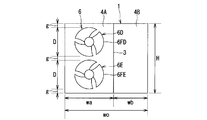
また、図4に示すように2台の室外送風機6D、6E、すなわち、プロペラファン6FD、6FEを室外機本体1の高さH方向に並設する場合には、これらプロペラファン6FD、6FEの直径Dを540mm以上にすることが好ましい。
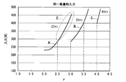
図5は、室外機本体1に、室外送風機を複数台設置し、それぞれ同一風量を送風するように運転したときのνと入力との関係を示すグラフである。
すなわち、図5は、上記(1)式で算出したときのνを横軸にし、各室外送風機のファンモータ6Mの合計の電気入力(消費電力)Wを縦軸にしたときの相対関係を示し、図中、曲線Aは、室外機本体1に、室外送風機を2台設置した場合(2ファン)の特性を示し、曲線Bは、室外送風機を3台設置した場合(3ファン)の特性を示し、曲線Cは、室外送風機を4台設置した場合(4ファン)の特性を示している。上記(1)式から、νの数値が大きくなるに従ってプロペラファン6Fの直径が小さくなる。
上記(1)式と(2)式を満たすνは、室外送風機が2台の場合(2ファン)が2.0≦ν≦2.5であり、室外送風機が3台の場合(3ファン)は、3.0≦ν≦3.5である。また、図5中、破線で示すE領域は、2ファンの場合において、νが2.5を超える場合であって、上記(2)式を満たさない領域を示す。
図5より、例えば2ファンでνが2.5の場合は、入力が約290W程度であるのに対し、νが2.5を超えるD領域の例えば2.8の場合は入力が約370W程度になる。一方、3ファンでνが3.0の場合は、入力が370Wより小さい約290W程度である。
したがって、2ファンでνが2.5を超えるE領域よりも、3ファンでνが3.0の場合の方が入力を小さくできる。
例えば、上記(1)式より、室外機本体1の高さHが1500mmの場合、2ファン(n=2)でνが2.5のときのプロペラファン6Fの直径Dは、540mmである。したがって、室外機本体1の横幅の制約等により、プロペラファン6Fの直径Dを540mm未満にする必要がある場合は、2ファンでプロペラファン6Fの直径Dを小さくする(νが2.5が大きくなるようにする)よりも、3ファン(n=3)にして、νが3.0となるようにプロペラファン6Fの直径Dを設定した方が入力を小さくすることができる。室外機本体1の高さHが1500mmの場合、3ファンでνが3.0のときのプロペラファン6Fの直径Dは、433mmである。
同様に、図5から明らかなように、3ファンでνが3.5を超える場合よりも、4ファンでνが4.0の場合の方が入力を小さくできる。
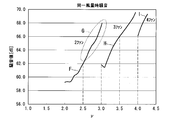
図6は、主に上記2ファン、3ファン、4ファンをそれぞれ同一風量で送風するように運転したときのνと騒音値(dB(デシベル))の関係を示す。図6中、F曲線は2ファンの場合の送風騒音特性を示し、G領域は2ファンで上記(2)式を満たさない領域、すなわち、νが2.5を超える領域を示す。また、H曲線は3ファンの場合、I曲線は4ファンの場合の送風騒音特性を示す。
図6より、例えば2ファンでνが2.5の場合は、騒音値が約62dB程度であるのに対し、νが2.5を超えるG領域の例えば2.8の場合は騒音値が約66dB程度になる。一方、3ファンでνが3.0の場合は、騒音値が約66dBより小さい約62dB程度である。
したがって、2ファンでνが2.5を超えるE領域よりも、3ファンでνが3.0の場合の方が騒音値を小さくできる。
同様に、図6から明らかなように、3ファンでνが3.5を超える場合よりも、4ファンでνが4.0の場合の方が騒音値を小さくできる。
したがって、本実施形態によれば、複数の室外送風機を室外機本体1の高さH方向(上下方向)に並設する場合、上記(1)、(2)式を満たすようにすることにより、同一風量を送風する場合、室外送風機のファンモータの入力と送風騒音の低減を共に図ることができる。
また、3台の室外送風機6A、6B、6Cを上下方向に延びる同一の送風機支持部材7に固定支持するようにしたので、各室外送風機6A、6B、6Cの位置決めが容易に正確にでき、各室外送風機6A、6B、6C間の間隔を均等にして、より低騒音化を図ることができる。
以上、本発明の幾つかの実施形態を説明したが、これらの実施形態は、例として提示したものであり、発明の範囲を限定することは意図していない。これら新規な実施形態は、その他の様々な形態で実施されることが可能であり、発明の要旨を逸脱しない範囲で、種々の省略、置換え、変更を行うことができる。これら実施形態やその変形は、発明の範囲や要旨に含まれるとともに、特許請求の範囲に記載された発明とその均等の範囲に含まれる。
R…室外機(熱源ユニット)、1…室外機本体(ユニット筐体)、3…仕切板、4A…熱交換室、4B…機械室、5…室外熱交換器、6…室外送風機、6F…プロペラファン、6M…ファンモータ、7…送風機支持部材、8…圧縮機。
Claims (3)
- ユニット筐体内を水平方向に仕切板で仕切り、その一方の空間を熱交換器および送風機を配置する熱交換室とし、他方の空間を圧縮機を配置する機械室とするとともに、前記送風機を前記熱交換室に上下方向に複数台並べて配置した熱源ユニットにおいて、
前記送風機は、ファンモータと、このファンモータの回転軸に嵌着されるプロペラファンとからなり、前記プロペラファンの設置数nと、前記ユニット筐体の高さH(mm)および前記プロペラファンの直径D(mm)との関係νが次の(1)式と(2)式を満たすように構成されていることを特徴とする熱源ユニット。
[数1]
ν=(H-50×(n+1))/D ……(1)
n≦ν≦(n+0.5) ……(2) - 前記送風機は、前記熱交換器に対向して設けられ、上下方向に延びる同一の支持部材に固定されていることを特徴とする請求項1記載の熱源ユニット。
- 前記送風機の台数が3台以上であることを特徴とする請求項2記載の熱源ユニット。
Priority Applications (1)
| Application Number | Priority Date | Filing Date | Title |
|---|---|---|---|
| CN201280015165.5A CN103443551B (zh) | 2011-03-28 | 2012-03-27 | 热源单元 |
Applications Claiming Priority (2)
| Application Number | Priority Date | Filing Date | Title |
|---|---|---|---|
| JP2011-069844 | 2011-03-28 | ||
| JP2011069844A JP2014111998A (ja) | 2011-03-28 | 2011-03-28 | 熱源ユニット |
Publications (1)
| Publication Number | Publication Date |
|---|---|
| WO2012133392A1 true WO2012133392A1 (ja) | 2012-10-04 |
Family
ID=46931109
Family Applications (1)
| Application Number | Title | Priority Date | Filing Date |
|---|---|---|---|
| PCT/JP2012/057908 Ceased WO2012133392A1 (ja) | 2011-03-28 | 2012-03-27 | 熱源ユニット |
Country Status (3)
| Country | Link |
|---|---|
| JP (1) | JP2014111998A (ja) |
| CN (1) | CN103443551B (ja) |
| WO (1) | WO2012133392A1 (ja) |
Cited By (1)
| Publication number | Priority date | Publication date | Assignee | Title |
|---|---|---|---|---|
| CN117109084A (zh) * | 2023-07-28 | 2023-11-24 | 青岛海尔中央空调有限公司 | 室外机、多联机空调系统及控制方法 |
Families Citing this family (2)
| Publication number | Priority date | Publication date | Assignee | Title |
|---|---|---|---|---|
| CN106440104A (zh) * | 2015-08-05 | 2017-02-22 | 美的集团武汉制冷设备有限公司 | 室外机及空调系统 |
| JP6718134B2 (ja) * | 2016-02-29 | 2020-07-08 | 株式会社富士通ゼネラル | 空気調和機の室外機 |
Citations (4)
| Publication number | Priority date | Publication date | Assignee | Title |
|---|---|---|---|---|
| JPH03168543A (ja) * | 1989-10-27 | 1991-07-22 | Carrier Corp | 空調システム用熱交換ユニット |
| JPH11337129A (ja) * | 1998-05-29 | 1999-12-10 | Yanmar Diesel Engine Co Ltd | 多連ファン構造のエンジンヒートポンプ |
| JP2003106564A (ja) * | 2001-09-27 | 2003-04-09 | Toshiba Kyaria Kk | 空気調和機の室外機 |
| JP2003343489A (ja) * | 2002-05-30 | 2003-12-03 | Mitsubishi Electric Corp | 送風機、送風機の制御方法、および空気調和機 |
Family Cites Families (1)
| Publication number | Priority date | Publication date | Assignee | Title |
|---|---|---|---|---|
| JP2003097828A (ja) * | 2001-09-21 | 2003-04-03 | Toshiba Kyaria Kk | 空気調和機の室外機 |
-
2011
- 2011-03-28 JP JP2011069844A patent/JP2014111998A/ja not_active Withdrawn
-
2012
- 2012-03-27 WO PCT/JP2012/057908 patent/WO2012133392A1/ja not_active Ceased
- 2012-03-27 CN CN201280015165.5A patent/CN103443551B/zh active Active
Patent Citations (4)
| Publication number | Priority date | Publication date | Assignee | Title |
|---|---|---|---|---|
| JPH03168543A (ja) * | 1989-10-27 | 1991-07-22 | Carrier Corp | 空調システム用熱交換ユニット |
| JPH11337129A (ja) * | 1998-05-29 | 1999-12-10 | Yanmar Diesel Engine Co Ltd | 多連ファン構造のエンジンヒートポンプ |
| JP2003106564A (ja) * | 2001-09-27 | 2003-04-09 | Toshiba Kyaria Kk | 空気調和機の室外機 |
| JP2003343489A (ja) * | 2002-05-30 | 2003-12-03 | Mitsubishi Electric Corp | 送風機、送風機の制御方法、および空気調和機 |
Cited By (1)
| Publication number | Priority date | Publication date | Assignee | Title |
|---|---|---|---|---|
| CN117109084A (zh) * | 2023-07-28 | 2023-11-24 | 青岛海尔中央空调有限公司 | 室外机、多联机空调系统及控制方法 |
Also Published As
| Publication number | Publication date |
|---|---|
| JP2014111998A (ja) | 2014-06-19 |
| CN103443551B (zh) | 2016-06-29 |
| CN103443551A (zh) | 2013-12-11 |
Similar Documents
| Publication | Publication Date | Title |
|---|---|---|
| CN109882932B (zh) | 空调室内机和空调器 | |
| US7461518B2 (en) | Fan and air conditioner | |
| KR101927440B1 (ko) | 공기 조화기 | |
| JP6122281B2 (ja) | 換気装置及びその熱交換ユニット | |
| CN109084368B (zh) | 空调器 | |
| JP2016044825A (ja) | 室外機及びこの室外機を備えた空気調和機 | |
| JP2008145093A (ja) | 空気調和機の室外機 | |
| JP6370406B2 (ja) | 空気調和機 | |
| CN208059129U (zh) | 整体式空调器 | |
| KR102410402B1 (ko) | 공기 조화기용 실외기 | |
| JPWO2006068210A1 (ja) | 空気調和装置の室外機 | |
| CN204494639U (zh) | 空调室外机及空调器 | |
| CN103443551B (zh) | 热源单元 | |
| CN204757291U (zh) | 风机系统及空调器 | |
| JP2012229901A (ja) | 冷凍空調装置及び冷凍空調システム | |
| CN202432610U (zh) | 一种落地式空调器室内机 | |
| CN109724158A (zh) | 立式空调室内机 | |
| JP6233120B2 (ja) | ダクト型空気調和機 | |
| JP2014092333A (ja) | 熱交換換気装置 | |
| CN202792239U (zh) | 下吹风嵌入式空调机室内机 | |
| JP5860752B2 (ja) | 空気調和機 | |
| CN208059126U (zh) | 整体式空调器 | |
| CN205579757U (zh) | 壁挂式空调室内机及空调器 | |
| CN208059124U (zh) | 整体式空调器 | |
| JP6172578B2 (ja) | ダクト型空気調和機 |
Legal Events
| Date | Code | Title | Description |
|---|---|---|---|
| 121 | Ep: the epo has been informed by wipo that ep was designated in this application |
Ref document number: 12765028 Country of ref document: EP Kind code of ref document: A1 |
|
| WWE | Wipo information: entry into national phase |
Ref document number: 1301005221 Country of ref document: TH |
|
| NENP | Non-entry into the national phase |
Ref country code: DE |
|
| 122 | Ep: pct application non-entry in european phase |
Ref document number: 12765028 Country of ref document: EP Kind code of ref document: A1 |
|
| NENP | Non-entry into the national phase |
Ref country code: JP |