WO2012132542A1 - 自動変速機の制御装置 - Google Patents
自動変速機の制御装置 Download PDFInfo
- Publication number
- WO2012132542A1 WO2012132542A1 PCT/JP2012/052373 JP2012052373W WO2012132542A1 WO 2012132542 A1 WO2012132542 A1 WO 2012132542A1 JP 2012052373 W JP2012052373 W JP 2012052373W WO 2012132542 A1 WO2012132542 A1 WO 2012132542A1
- Authority
- WO
- WIPO (PCT)
- Prior art keywords
- range
- oil
- select lever
- signal
- range signal
- Prior art date
- Legal status (The legal status is an assumption and is not a legal conclusion. Google has not performed a legal analysis and makes no representation as to the accuracy of the status listed.)
- Ceased
Links
Images
Classifications
-
- F—MECHANICAL ENGINEERING; LIGHTING; HEATING; WEAPONS; BLASTING
- F16—ENGINEERING ELEMENTS AND UNITS; GENERAL MEASURES FOR PRODUCING AND MAINTAINING EFFECTIVE FUNCTIONING OF MACHINES OR INSTALLATIONS; THERMAL INSULATION IN GENERAL
- F16H—GEARING
- F16H61/00—Control functions within control units of change-speed- or reversing-gearings for conveying rotary motion ; Control of exclusively fluid gearing, friction gearing, gearings with endless flexible members or other particular types of gearing
- F16H61/12—Detecting malfunction or potential malfunction, e.g. fail safe ; Circumventing or fixing failures
-
- F—MECHANICAL ENGINEERING; LIGHTING; HEATING; WEAPONS; BLASTING
- F16—ENGINEERING ELEMENTS AND UNITS; GENERAL MEASURES FOR PRODUCING AND MAINTAINING EFFECTIVE FUNCTIONING OF MACHINES OR INSTALLATIONS; THERMAL INSULATION IN GENERAL
- F16H—GEARING
- F16H61/00—Control functions within control units of change-speed- or reversing-gearings for conveying rotary motion ; Control of exclusively fluid gearing, friction gearing, gearings with endless flexible members or other particular types of gearing
- F16H61/18—Preventing unintentional or unsafe shift, e.g. preventing manual shift from highest gear to reverse gear
-
- F—MECHANICAL ENGINEERING; LIGHTING; HEATING; WEAPONS; BLASTING
- F16—ENGINEERING ELEMENTS AND UNITS; GENERAL MEASURES FOR PRODUCING AND MAINTAINING EFFECTIVE FUNCTIONING OF MACHINES OR INSTALLATIONS; THERMAL INSULATION IN GENERAL
- F16H—GEARING
- F16H61/00—Control functions within control units of change-speed- or reversing-gearings for conveying rotary motion ; Control of exclusively fluid gearing, friction gearing, gearings with endless flexible members or other particular types of gearing
- F16H61/12—Detecting malfunction or potential malfunction, e.g. fail safe ; Circumventing or fixing failures
- F16H2061/1256—Detecting malfunction or potential malfunction, e.g. fail safe ; Circumventing or fixing failures characterised by the parts or units where malfunctioning was assumed or detected
- F16H2061/1284—Detecting malfunction or potential malfunction, e.g. fail safe ; Circumventing or fixing failures characterised by the parts or units where malfunctioning was assumed or detected the failing part is a sensor
-
- F—MECHANICAL ENGINEERING; LIGHTING; HEATING; WEAPONS; BLASTING
- F16—ENGINEERING ELEMENTS AND UNITS; GENERAL MEASURES FOR PRODUCING AND MAINTAINING EFFECTIVE FUNCTIONING OF MACHINES OR INSTALLATIONS; THERMAL INSULATION IN GENERAL
- F16H—GEARING
- F16H61/00—Control functions within control units of change-speed- or reversing-gearings for conveying rotary motion ; Control of exclusively fluid gearing, friction gearing, gearings with endless flexible members or other particular types of gearing
- F16H61/16—Inhibiting or initiating shift during unfavourable conditions , e.g. preventing forward-reverse shift at high vehicle speed, preventing engine overspeed
- F16H2061/168—Forced shifts into neutral for safety reasons, e.g. in case of transmission failure or emergency braking
-
- F—MECHANICAL ENGINEERING; LIGHTING; HEATING; WEAPONS; BLASTING
- F16—ENGINEERING ELEMENTS AND UNITS; GENERAL MEASURES FOR PRODUCING AND MAINTAINING EFFECTIVE FUNCTIONING OF MACHINES OR INSTALLATIONS; THERMAL INSULATION IN GENERAL
- F16H—GEARING
- F16H59/00—Control inputs to control units of change-speed- or reversing-gearings for conveying rotary motion
- F16H59/02—Selector apparatus
- F16H59/04—Ratio selector apparatus
- F16H59/044—Ratio selector apparatus consisting of electrical switches or sensors
Definitions
- the present invention relates to a control device for an automatic transmission.
- JP 6-147316A discloses that a shift position is processed as an N range when the select lever is between an N range which is a non-traveling range and a D range which is a traveling range.
- the inhibitor switch when the inhibitor switch outputs a signal corresponding to an intermediate position between the D range signal and the N range signal due to, for example, a failure during driving, the shift position is processed as the N range. There is a problem that the driving force generated at the power source is not transmitted, and the vehicle decelerates during traveling against the driver's intention.
- the present invention has been invented to solve such a problem, and even when the inhibitor switch outputs a signal corresponding to an intermediate position between the D range signal and the N range signal during traveling, the drive source
- the purpose is to transmit the driving force generated by the vehicle and suppress deceleration unintended by the driver during traveling.
- a control device for an automatic transmission includes a friction engagement element that transmits rotation when oil is supplied and fastened, and includes a frictional fastening element that blocks transmission of rotation when oil is discharged and released. It is the control apparatus of the automatic transmission which controls a transmission.
- the control device for the automatic transmission is mechanically connected to a select lever, and supplies a first hydraulic pressure control unit that supplies and discharges oil to and from the frictional engagement element in accordance with the operation position of the select lever, and a range in accordance with the operation position of the select lever.
- a range signal output unit that outputs a signal
- a second hydraulic control unit that is arranged in series with the first hydraulic control unit and that supplies and discharges oil to and from the frictional engagement element according to the range signal, and determines whether the vehicle is stopped
- the second hydraulic control unit can supply oil to the frictional engagement element when the signal corresponding to the intermediate position between the travel range and the non-travel range is output by the range signal output unit and the vehicle is traveling. An oil passage is formed.
- the frictional engagement element is immediately released without releasing the frictional engagement element. Since it can be fastened, deceleration that is not intended by the driver during traveling can be suppressed.
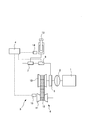
- FIG. 1 is a schematic configuration diagram of a vehicle having a control device for an automatic transmission according to an embodiment of the present invention.
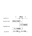
- FIG. 2 is a diagram showing a region where the manual valve hydraulic pressure can be generated by operating the select lever and a conduction region of the inhibitor switch.
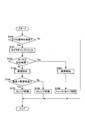
- FIG. 3 is a flowchart for explaining the signal processing control of the inhibitor switch in the embodiment of the present invention.
- FIG. 1 is a schematic configuration diagram of a vehicle having a control device for an automatic transmission according to the present embodiment.
- the vehicle includes an engine 1, a torque converter 2, a continuously variable transmission 3, and a controller 4.
- the continuously variable transmission 3 includes a forward / reverse switching mechanism 5, a variator 6, a manual valve 7, and a solenoid 8.
- the forward / reverse switching mechanism 5 switches the engagement state of the forward clutch or the reverse clutch by the oil supplied and discharged via the manual valve 7 and the solenoid 8.
- the variator 6 includes a primary pulley 10, a secondary pulley 11, and a belt 12 that is wound around the primary pulley 10 and the secondary pulley 11.
- the rotation generated in the engine 1 is transmitted in the order of the torque converter 2, the continuously variable transmission 3, and the drive wheels (not shown), and the vehicle travels.
- the manual valve 7 is mechanically connected to the select lever 13, forms an oil passage based on the operation of the select lever 13, and supplies / discharges oil to / from the forward / reverse switching mechanism 5.
- the manual valve 7 supplies oil to the forward / reverse switching mechanism 5 when the select lever 13 is in the travel range (D range or R range) and at an intermediate position between the travel range and the non-travel range (N range or P range). Form an oil passage.
- the manual valve 7 forms an oil passage so that oil is discharged from the forward / reverse switching mechanism 5 when the select lever 13 is in the non-traveling range.
- the solenoid 8 forms an oil passage based on a signal output from the inhibitor switch 14 and supplies / discharges oil to / from the forward / reverse switching mechanism 5.
- the solenoid 8 is arranged in series with the manual valve 7.
- the arrangement in series means that when oil is supplied to the forward / reverse switching mechanism 5, the manual valve 7 and the solenoid 8 are arranged along the oil flow direction. Therefore, when the oil passage is formed so that the manual valve 7 supplies oil to the forward / reverse switching mechanism 5 and the solenoid 8 forms the oil path so as to supply oil to the forward / reverse switching mechanism 5, Oil is supplied to the forward / reverse switching mechanism 5 through the manual valve 7 and the solenoid 8.
- the inhibitor switch 14 outputs a range signal according to the position of the select lever 13.
- the inhibitor switch 14 transmits a D range signal when the select lever 13 is detented to a position where the select lever 13 is in the D range.
- the inhibitor switch 14 is used when the select lever 13 is at an intermediate position between the travel range and the non-travel range adjacent to the travel range, that is, between the detent position of the travel range and the non-travel range. Outputs a running range signal and a non-running range signal as signals corresponding to the intermediate position. As an example, the inhibitor switch 14 outputs a D range signal and an N range signal when the select lever 13 is at an intermediate position between the D range and the N range adjacent to the D range.
- the inhibitor switch 14 outputs a signal corresponding to the intermediate position even when the contact for outputting each range signal is short-circuited.
- the contact of the N range is short-circuited.
- the controller 4 includes a CPU, a ROM, a RAM, and the like.
- the function of the continuously variable transmission 3 is exhibited by the CPU reading the program stored in the ROM.
- the controller 4 controls the solenoid 8 on the basis of the signal from the inhibitor switch 14 and the signal from the vehicle speed sensor 15, and supplies / discharges oil to / from the forward / reverse switching mechanism 5.
- FIG. 2 is a diagram showing a region where the hydraulic pressure can be generated by the manual valve 7 by the operation of the select lever 13 and a conduction region of the inhibitor switch 14.
- the manual valve 7 When the manual valve 7 is in the region where the hydraulic pressure can be generated, the manual valve 7 forms an oil passage so as to supply oil to the forward / reverse switching mechanism 5.
- the inhibitor switch 14 outputs a signal corresponding to the conduction region in each conduction region.
- the manual valve 7 forms an oil passage so as to discharge oil from the forward clutch.
- the inhibitor switch 14 outputs only the N range signal, and the solenoid 8 forms an oil passage so as to discharge oil from the forward clutch.
- the manual valve 7 moves forward.
- An oil passage is formed so as to supply oil to the clutch.
- the manual valve 7 gradually opens as the select lever 13 approaches the detent position of the D range, and the amount of oil that can be supplied to the forward clutch per unit time increases.
- the inhibitor switch 14 outputs an N range signal and a D range signal.
- the controller 4 processes the signal from the inhibitor switch 14 as an N range signal, and the solenoid 8 discharges oil from the forward clutch. An oil passage is formed. Therefore, no oil is supplied to the forward clutch, and the forward clutch is released.
- the inhibitor switch 14 When the select lever 13 reaches the detent position of the D range, the inhibitor switch 14 outputs only the D range signal, and the solenoid 8 forms an oil passage so that oil is gradually supplied to the forward clutch. As a result, oil is gradually supplied to the forward clutch, and the forward clutch is fastened.
- step S100 the controller 4 determines whether or not a signal corresponding to the intermediate position is received from the inhibitor switch 14. Specifically, the controller 4 determines whether or not two signals of a travel range signal and a non-travel range signal adjacent to the travel range are received.
- the travel range signal will be described as a D range signal and the non-travel range signal as an N range signal, but the same control is performed when the travel range signal is an R range signal. If the controller 4 has received two signals, the process proceeds to step S101. If either signal or neither signal has been received, the controller 4 ends this control.
- step S101 the controller 4 increments a timer indicating that two signals are received.
- the controller 4 adds “1” to the previous value.
- the initial value of the timer is “0”.
- step S102 the controller 4 compares the timer value with a predetermined time. Then, the controller 4 proceeds to step S103 when the timer value is smaller than the predetermined time, and proceeds to step S107 when the timer value exceeds the predetermined time.
- the predetermined time is a time during which it is possible to determine that the inhibitor switch 14 or the select lever 13 is abnormal, and is set in advance. When the inhibitor switch 14 or the select lever 13 is abnormal, it means that the two signals of the travel range signal and the non-travel range signal are continuously output for a longer time than normal.
- step S103 the controller 4 detects the vehicle speed by the vehicle speed sensor 15.
- step S104 the controller 4 compares the vehicle speed with a predetermined vehicle speed. Then, the controller 4 determines that the vehicle is traveling when the vehicle speed is higher than the predetermined vehicle speed, and proceeds to step S105, and determines that the vehicle is stopped when the vehicle speed is equal to or lower than the predetermined vehicle speed. Proceed to step S106.
- the predetermined vehicle speed is a vehicle speed capable of determining whether or not the vehicle is stopped.
- step S105 the controller 4 processes the signal of the inhibitor switch 14 as a D range signal.
- the controller 4 uses the signal of the inhibitor switch 14 as the D range signal. To process.
- this processing is performed when the N-range contact is short-circuited while traveling in the D range and the N-range signal is output by the inhibitor switch 14 in addition to the D-range signal, This is executed when the elbow or the like hits and the select lever 13 is held at an intermediate position between the D range and the N range.
- step S106 the controller 4 processes the signal of the inhibitor switch 14 as an N range signal.
- the controller 4 sends the signal from the inhibitor switch 14 to the N-range signal. Process as.
- the solenoid 8 forms an oil passage so as to discharge oil from the forward clutch, and the forward clutch is released.
- step S107 the controller 4 notifies the driver of the abnormality.
- the controller 4 notifies the driver of the abnormality by turning on or blinking a warning lamp, for example.
- a warning lamp for example.
- step S108 the controller 4 performs fail-safe control. Specifically, the controller 4 processes the signal of the inhibitor switch 14 as a D range signal. As a result, the solenoid 8 forms an oil passage so as to supply oil to the forward clutch, so that the vehicle can travel. Even when fail-safe control is being performed, when the vehicle is stopped, if the select lever 13 is operated to the non-traveling range, the manual valve 7 is switched forward and backward in conjunction with the operation of the select lever 13. An oil passage is formed so that oil is discharged from the mechanism 5, and the oil is discharged by the manual valve 7. Accordingly, the forward clutch or the reverse brake is released, so that the rotation of the engine 1 is not transmitted to the drive wheels, and the vehicle can be stopped.
- the solenoid 8 forms an oil passage so that oil is supplied to the forward / reverse switching mechanism 5.
- an abnormality occurs in the select lever 13 or the inhibitor switch 14, and the inhibitor switch 14 outputs a signal corresponding to an intermediate position between the traveling range and the non-driving range, that is, the traveling range signal and the non-driving range signal.
- oil can be supplied to the forward / reverse switching mechanism 5 and the forward clutch or the reverse brake can be fastened, so that deceleration that is not intended by the driver can be suppressed and traveling can be continued.
- the solenoid moves the forward / reverse switching mechanism by the solenoid.
- the oil passage is formed so as to supply oil, oil cannot be supplied to the forward / reverse switching mechanism.
- the mismatch is resolved and oil is supplied from the manual valve to the forward / reverse switching mechanism.
- the select lever 13 When the select lever 13 is changed from the non-traveling range position to the traveling range position, the timing at which the inhibitor switch 14 outputs a traveling range signal and the timing at which the oil path from the manual valve 7 to the forward / reverse switching mechanism 5 is formed. Simultaneously is difficult due to manufacturing variations.
- the select lever 13 in order to form an oil passage so that oil can be reliably supplied from the manual valve 7 to the forward / reverse switching mechanism 5 when the select lever 13 is in the travel range position, the select lever 13 is not connected to the travel range.
- the manual valve 7 forms an oil passage to the forward / reverse switching mechanism 5 at an intermediate position with respect to the travel range.
- the solenoid 8 moves the oil forward and backward when the vehicle is stopped.
- An oil passage is formed so as to be discharged from the switching mechanism 5.
- the selector lever 13 or the inhibitor switch 14 When the time for which the inhibitor switch 14 outputs the traveling range signal and the non-driving range signal is longer than the predetermined time, the selector lever 13 or the inhibitor switch 14 is informed that an abnormality has occurred. Thereby, when the select lever 13 is in an intermediate position between the travel range and the non-travel range, it is possible to prompt the user to change the select lever 13 to an appropriate position. Further, when the inhibitor switch 14 breaks down and the traveling range signal and the non-driving range signal are output, the driver can be informed that repair is necessary.
- the continuously variable transmission is described as the automatic transmission.
- the present invention is not limited to this, and a stepped transmission may be used.
- the stepped transmission may be controlled so as to achieve a predetermined shift speed.
- the inhibitor switch 14 outputs a travel range signal and a non-travel range signal as signals corresponding to the intermediate position, but is not limited thereto, and may output a zero signal or another signal.
- the zero signal means a state in which no range signal is output.
Landscapes
- Engineering & Computer Science (AREA)
- General Engineering & Computer Science (AREA)
- Mechanical Engineering (AREA)
- Control Of Transmission Device (AREA)
Abstract
セレクトレバーと機械的に連結し、セレクトレバーの操作位置に応じて摩擦締結要素に油を供給する第1油圧制御部と、レンジ信号出力部が出力するレンジ信号に応じて摩擦締結要素に油を供給する第2油圧制御部とを備え、第2油圧制御部は、レンジ信号出力部によって走行レンジおよび非走行レンジとの中間位置に対応する信号が出力されており、かつ車両が走行している場合に、摩擦締結要素に油を供給する油路を形成する。
Description
本発明は自動変速機の制御装置に関するものである。
従来、セレクトレバーが非走行レンジであるNレンジと走行レンジであるDレンジとの間にある場合には、変速位置がNレンジとしての処理を行うものが、JP6-147316Aに開示されている。
上記の発明では、セレクトレバーがDレンジに完全に切り替えられ、インヒビタスイッチが出力した信号がDレンジ信号となった後に、油圧回路における弁の切り替えを行い、変速要素の切り替えを完了させている。
しかし、走行中にインヒビタスイッチが、例えば故障などによりDレンジ信号とNレンジ信号との中間位置に対応する信号を出力している場合には、変速位置がNレンジとしての処理を行うため、駆動源で発生した駆動力が伝達されず、運転者の意図に反して走行中に車両が減速する、といった問題点がある。
本発明はこのような問題点を解決するために発明されたもので、走行中にインヒビタスイッチがDレンジ信号とNレンジ信号との中間位置に対応する信号を出力している場合でも、駆動源で発生した駆動力を伝達し、走行中に運転者の意図しない減速を抑制することを目的とする。
本発明のある態様に係る自動変速機の制御装置は、油が供給されて締結することによって回転を伝達し、油が排出されて解放することによって回転の伝達を遮断する摩擦締結要素を備える自動変速機を制御する自動変速機の制御装置である。自動変速機の制御装置は、セレクトレバーと機械的に連結し、セレクトレバーの操作位置に応じて摩擦締結要素に油を給排する第1油圧制御部と、セレクトレバーの操作位置に応じたレンジ信号を出力するレンジ信号出力部と、第1油圧制御部と直列に配置され、レンジ信号に応じて摩擦締結要素に油を給排する第2油圧制御部と、車両が停車しているかどうか判定する停車判定部とを備える。第2油圧制御部は、レンジ信号出力部によって走行レンジおよび非走行レンジとの中間位置に対応する信号が出力されており、かつ車両が走行している場合に、摩擦締結要素に油を供給可能となる油路を形成する。
この態様によると、走行中にレンジ信号出力部が走行レンジおよび非走行レンジとの中間位置に対応する信号を出力している場合でも、即座に摩擦締結要素を解放することなく、摩擦締結要素を締結することができるので、走行中に運転者が意図しない減速を抑制することができる。
以下において、本発明の実施形態について図を参照しながら説明する。
図1は、本実施形態の自動変速機の制御装置を有する車両の概略構成図である。
車両は、エンジン1と、トルクコンバータ2と、無段変速機3と、コントローラ4とを備える。
無段変速機3は、前後進切換機構5と、バリエータ6と、マニュアルバルブ7と、ソレノイド8とを備える。
前後進切換機構5は、マニュアルバルブ7、ソレノイド8を介して給排される油によって前進クラッチまたは後進クラッチの締結状態を切り替える。
バリエータ6は、プライマリプーリ10と、セカンダリプーリ11と、プライマリプーリ10とセカンダリプーリ11とに掛け回されたベルト12とを備える。
エンジン1で発生した回転が、トルクコンバータ2、無段変速機3、駆動輪(図示せず)の順に伝達されて、車両は走行する。
マニュアルバルブ7は、セレクトレバー13と機械的に連結しており、セレクトレバー13の操作に基づいて油路を形成して、前後進切換機構5に油を給排する。マニュアルバルブ7は、セレクトレバー13が走行レンジ(DレンジまたはRレンジ)、および走行レンジと非走行レンジ(NレンジまたはPレンジ)との中間位置において、前後進切換機構5に油を供給するように油路を形成する。マニュアルバルブ7は、セレクトレバー13が非走行レンジにある場合には、前後進切換機構5から油を排出するように油路を形成する。
ソレノイド8は、インヒビタスイッチ14が出力する信号に基づいて油路を形成して、前後進切換機構5に油を給排する。ソレノイド8は、マニュアルバルブ7と直列に配置されている。直列に配置とは、前後進切換機構5に油を供給する場合に、油の流れ方向に沿ってマニュアルバルブ7とソレノイド8とが配置されることを言う。そのため、マニュアルバルブ7が油を前後進切換機構5に供給するように油路を形成し、さらにソレノイド8が油を前後進切換機構5に供給するように油路を形成している場合に、マニュアルバルブ7、ソレノイド8を通って前後進切換機構5に油が供給される。一方、マニュアルバルブ7、またはソレノイド8のいずれか一方が、油を前後進切換機構5に供給するように油路を形成している場合であっても、もう一方が、油を前後進切換機構5から排出するように油路を形成している場合には、前後進切換機構5から油が排出される。
インヒビタスイッチ14は、セレクトレバー13の位置に応じてレンジ信号を出力する。一例としては、インヒビタスイッチ14は、セレクトレバー13がDレンジとなる位置にディテントされている場合には、Dレンジ信号を発信する。
さらに、インヒビタスイッチ14は、セレクトレバー13が走行レンジと走行レンジに隣接する非走行レンジとの中間位置にある場合、つまり走行レンジのディテント位置と非走行レンジのディテント位置との間にある場合には、中間位置に対応する信号として走行レンジ信号と非走行レンジ信号とを出力する。一例としては、インヒビタスイッチ14は、セレクトレバー13がDレンジとDレンジに隣接するNレンジとの中間位置にある場合には、Dレンジ信号とNレンジ信号とを出力する。
また、インヒビタスイッチ14は、各レンジ信号を出力するための接点がショートした場合にも中間位置に対応する信号を出力する。一例としては、セレクトレバー13がDレンジに位置する場合に、Nレンジの接点がショートした場合である。
コントローラ4は、CPU、ROM、RAMなどから構成されている。CPUがROMに格納したプログラムを読み出すことで、無段変速機3の機能が発揮される。
コントローラ4は、インヒビタスイッチ14の信号、車速センサ15の信号に基づいて、ソレノイド8を制御し、前後進切換機構5に油を給排する。
ここで、セレクトレバー13がNレンジからDレンジへ操作される場合を一例として、図2を用いながら前後進切換機構5における油の給排について説明する。図2は、セレクトレバー13の操作によるマニュアルバルブ7の油圧発生可能領域と、インヒビタスイッチ14の導通域とを示す図である。マニュアルバルブ7が油圧発生可能領域となると、マニュアルバルブ7は前後進切換機構5に油を供給するように油路を形成する。インヒビタスイッチ14は、各導通領域では導通領域に対応する信号を出力する。
セレクトレバー13がNレンジにディテントされている場合には、マニュアルバルブ7は前進クラッチから油を排出するように油路を形成している。また、インヒビタスイッチ14はNレンジ信号のみを出力しており、ソレノイド8は前進クラッチから油を排出するように油路を形成している。
セレクトレバー13がNレンジのディテント位置からDレンジのディテント位置まで移動している場合、つまり、セレクトレバー13がNレンジとDレンジとの中間位置を移動している途中において、マニュアルバルブ7は前進クラッチに油を供給するように油路を形成する。なお、マニュアルバルブ7は、セレクトレバー13がDレンジのディテント位置に近づくにつれて、徐々に開いていき、前進クラッチに単位時間当たりに供給可能な油が多くなる。インヒビタスイッチ14はNレンジ信号とDレンジ信号とを出力しており、この場合、コントローラ4はインヒビタスイッチ14からの信号をNレンジ信号として処理し、ソレノイド8は前進クラッチから油を排出するように油路を形成している。そのため、前進クラッチには油は供給されず、前進クラッチは解放されている。
セレクトレバー13がDレンジのディテント位置となると、インヒビタスイッチ14はDレンジ信号のみを出力し、ソレノイド8は徐々に前進クラッチに油を供給するように油路を形成する。これによって、前進クラッチには徐々に油が供給され、前進クラッチは締結する。
次に本実施形態のインヒビタスイッチ14の信号処理制御について図3のフローチャートを用いて説明する。本制御は、所定の間隔で繰り返し実行される。
ステップS100では、コントローラ4は、インヒビタスイッチ14から、中間位置に対応する信号を受信しているかどうか判定する。具体的には、コントローラ4は走行レンジ信号および走行レンジに隣接する非走行レンジ信号の2つの信号を受信しているかどうか判定する。ここでは、走行レンジ信号をDレンジ信号、非走行レンジ信号をNレンジ信号として説明するが、走行レンジ信号がRレンジ信号である場合も同様の制御を行う。コントローラ4は、2つの信号を受信している場合にはステップS101へ進み、いずれか一方の信号、またはどちらの信号も受信していない場合には本制御を終了する。
ステップS101では、コントローラ4は、2つの信号を受信していることを示すタイマをインクリメントする。コントローラ4は前回の値に「1」を加算する。なお、タイマの初期値は「0」である。
ステップS102では、コントローラ4は、タイマの値と所定時間とを比較する。そして、コントローラ4は、タイマの値が所定時間よりも小さい場合にはステップS103へ進み、タイマの値が所定時間以上となるとステップS107へ進む。所定時間は、インヒビタスイッチ14またはセレクトレバー13が異常であると判定可能な時間であり、予め設定されている。インヒビタスイッチ14またはセレクトレバー13が異常とは、走行レンジ信号および非走行レンジ信号の2つの信号が通常時よりも長い時間継続して出力されていることを意味する。例えばインヒビタスイッチ14で各レンジ信号を出力するための接点がショートして、本来ならば出力しない信号をインヒビタスイッチ14が出力している場合や、肘などがセレクトレバー13に当たり、セレクトレバー13が本来ディテントされない位置(各レンジの中間位置)に保持されている場合などである。
ステップS103では、コントローラ4は、車速センサ15によって車速を検出する。
ステップS104では、コントローラ4は、車速と所定車速とを比較する。そして、コントローラ4は、車速が所定車速よりも大きい場合には車両が走行していると判定し、ステップS105へ進み、車速が所定車速以下である場合には車両が停車していると判定しステップS106へ進む。所定車速は車両が停車しているかどうか判定可能が車速である。
ステップS105では、コントローラ4は、インヒビタスイッチ14の信号をDレンジ信号として処理する。インヒビタスイッチ14からDレンジ信号およびNレンジ信号を受信し、タイマの値が所定時間よりも小さく、かつ車速が所定車速よりも大きい場合には、コントローラ4はインヒビタスイッチ14の信号をDレンジ信号として処理する。
具体的には、この処理は、Dレンジで走行中にNレンジ接点がショートし、Dレンジ信号に加えてNレンジ信号がインヒビタスイッチ14によって出力されている場合や、走行中にセレクトレバー13に肘などが当たり、セレクトレバー13がDレンジとNレンジとの中間位置に保持されている場合などに実行される。
このような場合でも本実施形態では、マニュアルバルブ7によって前進クラッチに油を供給するように油路が形成され、ソレノイド8によって前進クラッチに油を供給するように油路が形成されると前進クラッチに油が供給されるので、前進クラッチは締結し、エンジン1の回転が駆動輪に伝達される。
ステップS106では、コントローラ4は、インヒビタスイッチ14の信号をNレンジ信号として処理する。インヒビタスイッチ14からDレンジ信号およびNレンジ信号2つの信号を受信し、タイマが所定時間よりも小さく、かつ車速が所定車速以下である場合には、コントローラ4はインヒビタスイッチ14の信号をNレンジ信号として処理する。
車速が所定車速以下である場合には、車両が停車しているので、ソレノイド8は前進クラッチから油を排出するように油路を形成し、前進クラッチが解放される。
ステップS107では、コントローラ4は、運転者に異常を報知する。コントローラ4は、例えば警告ランプを点灯または点滅させることで、運転者に異常を報知する。これによって、セレクトレバー13に肘などが当たり、セレクトレバー13がDレンジとNレンジとの中間位置にある場合には、運転者にセレクトレバー13の位置を適切な位置へ変更することを促す。また、インヒビタスイッチ14の接点がショートしている場合には、運転者に修理を行う必要があること知らせる。
ステップS108では、コントローラ4は、フェールセーフ制御を行う。具体的には、コントローラ4は、インヒビタスイッチ14の信号をDレンジ信号として処理する。これによって、ソレノイド8は前進クラッチに油を供給するように油路を形成するので、車両は走行可能である。なお、フェールセーフ制御を行っている場合でも、車両を停車させる際には、セレクトレバー13が非走行レンジに操作されると、セレクトレバー13の操作に連動して、マニュアルバルブ7が前後進切換機構5から油を排出するように油路を形成し、マニュアルバルブ7によって油が排出される。これによって、前進クラッチまたは後進ブレーキが解放されるので、エンジン1の回転が駆動輪に伝達されず、車両を停車させることができる。
本発明の実施形態の効果について説明する。
インヒビタスイッチ14が走行レンジ信号と非走行レンジ信号とを出力し、車両が走行している場合には、ソレノイド8は油を前後進切換機構5に供給するように油路を形成する。これによって、セレクトレバー13またはインヒビタスイッチ14に異常が生じ、インヒビタスイッチ14が走行レンジと非走行レンジとの中間位置に対応する信号、すなわち走行レンジ信号と非走行レンジ信号とを出力している場合でも、前後進切換機構5に油を供給し、前進クラッチまたは後進ブレーキを締結することができ、運転者の意図しない減速を抑制し、走行を継続することができる。
セレクトレバーが走行レンジ位置にあるにもかかわらずマニュアルバルブから前後進切換機構へ油を供給できるように油路が形成されていない、という不一致が生じている状態では、ソレノイドによって前後進切換機構に油を供給するように油路が形成されているにも関わらず、前後進切換機構に油を供給することができない。このような場合に、例えば、走行レンジで締結される締結要素への制御指令が完了して指令油圧が最大圧となった後に、上記不一致が解消されてマニュアルバルブから前後進切換機構へ油を供給する油路が形成されると、最大圧により締結要素が急締結されることによるショックが発生するおそれがある。
セレクトレバー13を非走行レンジ位置から走行レンジ位置に変更したときに、インヒビタスイッチ14が走行レンジ信号を出力するタイミングとマニュアルバルブ7から前後進切換機構5への油路が形成されるタイミングとを同時とすることは、製造バラツキにより困難である。本実施形態では、セレクトレバー13が走行レンジ位置にある場合に確実にマニュアルバルブ7から前後進切換機構5へ油を供給できるように油路を形成するために、セレクトレバー13が走行レンジと非走行レンジとの中間位置でマニュアルバルブ7は前後進切換機構5への油路が形成する。
インヒビタスイッチ14が走行レンジと非走行レンジとの中間位置に対応する信号、すなわち走行レンジ信号と非走行レンジ信号とを出力し、車両が停車している場合には、ソレノイド8は油を前後進切換機構5から排出するように油路を形成する。これによって、セレクトレバー13が走行レンジに変更されたときには、確実にマニュアルバルブ7から前後進切換機構5への油路が形成された状態とすることができ、ソレノイド8によって前後進切換機構5に油を供給するように油路を形成したときには確実に前後進切換機構5へ油を供給することができ、前後進切換機構5が急締結することを抑制し、ショックの発生を抑制することができる。また、セレクトレバー13が走行レンジと非走行レンジとの中間位置にある場合でも、ソレノイド8によって前進クラッチおよび後進ブレーキを解放することができ、車両を停車させることができる。
インヒビタスイッチ14が走行レンジ信号と非走行レンジ信号とを出力する時間が、所定時間よりも長い場合には、セレクトレバー13またはインヒビタスイッチ14に異常が生じていることを報知する。これによって、セレクトレバー13が走行レンジと非走行レンジとの中間位置にある場合には、セレクトレバー13を適切な位置に変更することを促すことができる。また、インヒビタスイッチ14が故障して走行レンジ信号と非走行レンジ信号とが出力されている場合には、運転者に修理が必要であることを知らせることができる。
以上、本発明の実施形態について説明したが、上記実施形態は本発明の適用例の一部を示したに過ぎず、本発明の技術的範囲を上記実施形態の具体的構成に限定する趣旨ではない。
本実施形態では、自動変速機として無段変速機を用いて説明したが、これに限られることはなく、有段変速機を用いてもよい。この場合、フェールセーフ制御を実行する場合には、所定の変速段となるよう有段変速機を制御してもよい。
本実施形態では、インヒビタスイッチ14は、中間位置に対応する信号として走行レンジ信号および非走行レンジ信号を出力しているが、これに限られず、ゼロ信号または他の信号を出力してもよい。ゼロ信号とは、いずれのレンジ信号も出力されていない状態を言う。
本願は2011年3月30日に日本国特許庁に出願された特願2011-74896に基づく優先権を主張し、この出願の全ての内容は参照により本明細書に組み込まれる。
Claims (3)
- 油が供給されて締結することによって回転を伝達し、前記油が排出されて解放することによって前記回転の伝達を遮断する摩擦締結要素を備える自動変速機を制御する自動変速機の制御装置であって、
セレクトレバーと機械的に連結し、前記セレクトレバーの操作位置に応じて前記摩擦締結要素に油を給排する第1油圧制御手段と、
前記セレクトレバーの操作位置に応じたレンジ信号を出力するレンジ信号出力手段と、
前記第1油圧制御手段と直列に配置され、前記レンジ信号に応じて前記摩擦締結要素に前記油を給排する第2油圧制御手段と、
車両が停車しているかどうか判定する停車判定手段とを備え、
前記第2油圧制御手段は、前記レンジ信号出力手段によって走行レンジおよび非走行レンジとの中間位置に対応する信号が出力されており、かつ前記車両が走行している場合に、前記摩擦締結要素に前記油を供給可能となる油路を形成する自動変速機の制御装置。 - 請求項1に記載の自動変速機の制御装置であって、
前記第1油圧制御手段は、前記セレクトレバーが走行レンジ、および前記走行レンジと前記走行レンジに隣接する非走行レンジとの間にある場合に、前記摩擦締結要素に前記油を供給可能となる油路を形成し、
前記第2油圧制御手段は、前記レンジ信号出力手段によって前記走行レンジおよび前記非走行レンジとの中間位置に対応する信号が出力されており、かつ前記車両が停車している場合に、前記摩擦締結要素から前記油を排出する油路を形成する自動変速機の制御装置。 - 請求項1または2に記載の自動変速機の制御装置であって、
前記レンジ信号出力手段によって前記走行レンジ信号および前記非走行レンジ信号が異常判定時間継続して出力された場合に、前記セレクトレバーまたは前記レンジ信号出力手段の異常を報知する異常報知手段を備える自動変速機の制御装置。
Applications Claiming Priority (2)
| Application Number | Priority Date | Filing Date | Title |
|---|---|---|---|
| JP2011074896 | 2011-03-30 | ||
| JP2011-074896 | 2011-03-30 |
Publications (1)
| Publication Number | Publication Date |
|---|---|
| WO2012132542A1 true WO2012132542A1 (ja) | 2012-10-04 |
Family
ID=46930309
Family Applications (1)
| Application Number | Title | Priority Date | Filing Date |
|---|---|---|---|
| PCT/JP2012/052373 Ceased WO2012132542A1 (ja) | 2011-03-30 | 2012-02-02 | 自動変速機の制御装置 |
Country Status (1)
| Country | Link |
|---|---|
| WO (1) | WO2012132542A1 (ja) |
Citations (6)
| Publication number | Priority date | Publication date | Assignee | Title |
|---|---|---|---|---|
| JPS6487946A (en) * | 1987-09-29 | 1989-04-03 | Aisin Seiki | Shift lever position detecting device |
| JPH01250647A (ja) * | 1988-03-31 | 1989-10-05 | Fuji Heavy Ind Ltd | シフトレバー位置信号の判定方法 |
| JPH0893899A (ja) * | 1994-09-20 | 1996-04-12 | Hino Motors Ltd | 自動車の制御装置 |
| JPH11190423A (ja) * | 1997-12-26 | 1999-07-13 | Toyota Autom Loom Works Ltd | 車両の安全装置 |
| JP2001108091A (ja) * | 1999-10-08 | 2001-04-20 | Toyota Motor Corp | 自動変速機のフェールセーフ装置 |
| JP2004251309A (ja) * | 2003-02-18 | 2004-09-09 | Nissan Motor Co Ltd | シフトバイワイヤ式自動変速機のレンジ選択装置 |
-
2012
- 2012-02-02 WO PCT/JP2012/052373 patent/WO2012132542A1/ja not_active Ceased
Patent Citations (6)
| Publication number | Priority date | Publication date | Assignee | Title |
|---|---|---|---|---|
| JPS6487946A (en) * | 1987-09-29 | 1989-04-03 | Aisin Seiki | Shift lever position detecting device |
| JPH01250647A (ja) * | 1988-03-31 | 1989-10-05 | Fuji Heavy Ind Ltd | シフトレバー位置信号の判定方法 |
| JPH0893899A (ja) * | 1994-09-20 | 1996-04-12 | Hino Motors Ltd | 自動車の制御装置 |
| JPH11190423A (ja) * | 1997-12-26 | 1999-07-13 | Toyota Autom Loom Works Ltd | 車両の安全装置 |
| JP2001108091A (ja) * | 1999-10-08 | 2001-04-20 | Toyota Motor Corp | 自動変速機のフェールセーフ装置 |
| JP2004251309A (ja) * | 2003-02-18 | 2004-09-09 | Nissan Motor Co Ltd | シフトバイワイヤ式自動変速機のレンジ選択装置 |
Similar Documents
| Publication | Publication Date | Title |
|---|---|---|
| KR101787249B1 (ko) | 동력 전달 장치 | |
| KR101472246B1 (ko) | 자동 변속기의 제어 장치 | |
| CN103161593A (zh) | 车辆控制装置及车辆的控制方法 | |
| JPWO2016152329A1 (ja) | 車両用自動変速機のフェール判定装置及び車両用自動変速機の制御装置 | |
| US20120283901A1 (en) | Control system for hybrid vehicle | |
| JP6922173B2 (ja) | 無段変速機の制御方法及び制御装置 | |
| JP6554545B2 (ja) | ベルト無段変速機及びその故障判断方法 | |
| JP6554546B2 (ja) | ベルト無段変速機及びその故障判断方法 | |
| JP6545891B2 (ja) | 自動変速機の異常検出装置 | |
| WO2018206572A1 (en) | Safety mode control apparatus and method for dual clutch transmission in vehicle | |
| WO2014157085A1 (ja) | 無段変速機および制御方法 | |
| WO2012132542A1 (ja) | 自動変速機の制御装置 | |
| JP6885409B2 (ja) | 無段変速機の制御方法、及び、無段変速システム | |
| JP2004116605A (ja) | 自動変速機 | |
| JP5669941B2 (ja) | 車両の制御装置 | |
| JP6152494B1 (ja) | 自動変速機の制御装置及び自動変速機の制御方法 | |
| JP6543540B2 (ja) | ベルト無段変速機及びその故障判断方法 | |
| JP5118859B2 (ja) | 自動変速機の制御装置 | |
| JP5810633B2 (ja) | 車両の制御装置 | |
| JP5476525B2 (ja) | 無段変速機 | |
| JP6718022B2 (ja) | 車両の制御装置及び車両の制御方法 | |
| JP6725234B2 (ja) | 車両の制御装置、及び車両の制御方法 | |
| JP6694286B2 (ja) | 車両の制御装置、及び車両の制御方法 | |
| JP6670620B2 (ja) | 車両用無段変速機の異常判定装置及び異常時対応装置 | |
| WO2013132899A1 (ja) | 無段変速機の変速制御装置及び変速制御方法 |
Legal Events
| Date | Code | Title | Description |
|---|---|---|---|
| 121 | Ep: the epo has been informed by wipo that ep was designated in this application |
Ref document number: 12764320 Country of ref document: EP Kind code of ref document: A1 |
|
| NENP | Non-entry into the national phase |
Ref country code: DE |
|
| 122 | Ep: pct application non-entry in european phase |
Ref document number: 12764320 Country of ref document: EP Kind code of ref document: A1 |
|
| NENP | Non-entry into the national phase |
Ref country code: JP |