WO2012132430A1 - 車載用充電装置 - Google Patents
車載用充電装置 Download PDFInfo
- Publication number
- WO2012132430A1 WO2012132430A1 PCT/JP2012/002152 JP2012002152W WO2012132430A1 WO 2012132430 A1 WO2012132430 A1 WO 2012132430A1 JP 2012002152 W JP2012002152 W JP 2012002152W WO 2012132430 A1 WO2012132430 A1 WO 2012132430A1
- Authority
- WO
- WIPO (PCT)
- Prior art keywords
- input current
- charger
- input
- input voltage
- current value
- Prior art date
- Legal status (The legal status is an assumption and is not a legal conclusion. Google has not performed a legal analysis and makes no representation as to the accuracy of the status listed.)
- Ceased
Links
Images

Classifications
-
- B—PERFORMING OPERATIONS; TRANSPORTING
- B60—VEHICLES IN GENERAL
- B60L—PROPULSION OF ELECTRICALLY-PROPELLED VEHICLES; SUPPLYING ELECTRIC POWER FOR AUXILIARY EQUIPMENT OF ELECTRICALLY-PROPELLED VEHICLES; ELECTRODYNAMIC BRAKE SYSTEMS FOR VEHICLES IN GENERAL; MAGNETIC SUSPENSION OR LEVITATION FOR VEHICLES; MONITORING OPERATING VARIABLES OF ELECTRICALLY-PROPELLED VEHICLES; ELECTRIC SAFETY DEVICES FOR ELECTRICALLY-PROPELLED VEHICLES
- B60L53/00—Methods of charging batteries, specially adapted for electric vehicles; Charging stations or on-board charging equipment therefor; Exchange of energy storage elements in electric vehicles
- B60L53/60—Monitoring or controlling charging stations
- B60L53/63—Monitoring or controlling charging stations in response to network capacity
-
- B—PERFORMING OPERATIONS; TRANSPORTING
- B60—VEHICLES IN GENERAL
- B60L—PROPULSION OF ELECTRICALLY-PROPELLED VEHICLES; SUPPLYING ELECTRIC POWER FOR AUXILIARY EQUIPMENT OF ELECTRICALLY-PROPELLED VEHICLES; ELECTRODYNAMIC BRAKE SYSTEMS FOR VEHICLES IN GENERAL; MAGNETIC SUSPENSION OR LEVITATION FOR VEHICLES; MONITORING OPERATING VARIABLES OF ELECTRICALLY-PROPELLED VEHICLES; ELECTRIC SAFETY DEVICES FOR ELECTRICALLY-PROPELLED VEHICLES
- B60L53/00—Methods of charging batteries, specially adapted for electric vehicles; Charging stations or on-board charging equipment therefor; Exchange of energy storage elements in electric vehicles
-
- H—ELECTRICITY
- H02—GENERATION; CONVERSION OR DISTRIBUTION OF ELECTRIC POWER
- H02J—ELECTRIC POWER NETWORKS; CIRCUIT ARRANGEMENTS OR SYSTEMS FOR SUPPLYING OR DISTRIBUTING ELECTRIC POWER; SYSTEMS FOR STORING ELECTRIC ENERGY
- H02J3/00—Circuit arrangements for AC mains or AC distribution networks
- H02J3/12—Arrangements for adjusting voltage in AC networks by changing a characteristic of the network load
- H02J3/14—Arrangements for adjusting voltage in AC networks by changing a characteristic of the network load by switching loads on to, or off from, the networks, e.g. progressively balanced loading
-
- H—ELECTRICITY
- H02—GENERATION; CONVERSION OR DISTRIBUTION OF ELECTRIC POWER
- H02J—ELECTRIC POWER NETWORKS; CIRCUIT ARRANGEMENTS OR SYSTEMS FOR SUPPLYING OR DISTRIBUTING ELECTRIC POWER; SYSTEMS FOR STORING ELECTRIC ENERGY
- H02J7/00—Circuit arrangements for charging or discharging batteries or for supplying loads from batteries
- H02J7/02—Circuit arrangements for charging or discharging batteries or for supplying loads from batteries for charging batteries from AC mains by converters
- H02J7/04—Regulation of charging current or voltage
-
- H—ELECTRICITY
- H02—GENERATION; CONVERSION OR DISTRIBUTION OF ELECTRIC POWER
- H02J—ELECTRIC POWER NETWORKS; CIRCUIT ARRANGEMENTS OR SYSTEMS FOR SUPPLYING OR DISTRIBUTING ELECTRIC POWER; SYSTEMS FOR STORING ELECTRIC ENERGY
- H02J7/00—Circuit arrangements for charging or discharging batteries or for supplying loads from batteries
- H02J7/90—Regulation of charging or discharging current or voltage
- H02J7/96—Regulation of charging or discharging current or voltage in response to battery voltage
-
- H—ELECTRICITY
- H02—GENERATION; CONVERSION OR DISTRIBUTION OF ELECTRIC POWER
- H02J—ELECTRIC POWER NETWORKS; CIRCUIT ARRANGEMENTS OR SYSTEMS FOR SUPPLYING OR DISTRIBUTING ELECTRIC POWER; SYSTEMS FOR STORING ELECTRIC ENERGY
- H02J2105/00—Networks for supplying or distributing electric power characterised by their spatial reach or by the load
- H02J2105/40—Networks for supplying or distributing electric power characterised by their spatial reach or by the load characterised by the loads connecting to the networks or being supplied by the networks
- H02J2105/42—Home appliances
-
- Y—GENERAL TAGGING OF NEW TECHNOLOGICAL DEVELOPMENTS; GENERAL TAGGING OF CROSS-SECTIONAL TECHNOLOGIES SPANNING OVER SEVERAL SECTIONS OF THE IPC; TECHNICAL SUBJECTS COVERED BY FORMER USPC CROSS-REFERENCE ART COLLECTIONS [XRACs] AND DIGESTS
- Y02—TECHNOLOGIES OR APPLICATIONS FOR MITIGATION OR ADAPTATION AGAINST CLIMATE CHANGE
- Y02B—CLIMATE CHANGE MITIGATION TECHNOLOGIES RELATED TO BUILDINGS, e.g. HOUSING, HOUSE APPLIANCES OR RELATED END-USER APPLICATIONS
- Y02B70/00—Technologies for an efficient end-user side electric power management and consumption
- Y02B70/30—Systems integrating technologies related to power network operation and communication or information technologies for improving the carbon footprint of the management of residential or tertiary loads, i.e. smart grids as climate change mitigation technology in the buildings sector, including also the last stages of power distribution and the control, monitoring or operating management systems at local level
- Y02B70/3225—Demand response systems, e.g. load shedding, peak shaving
-
- Y—GENERAL TAGGING OF NEW TECHNOLOGICAL DEVELOPMENTS; GENERAL TAGGING OF CROSS-SECTIONAL TECHNOLOGIES SPANNING OVER SEVERAL SECTIONS OF THE IPC; TECHNICAL SUBJECTS COVERED BY FORMER USPC CROSS-REFERENCE ART COLLECTIONS [XRACs] AND DIGESTS
- Y02—TECHNOLOGIES OR APPLICATIONS FOR MITIGATION OR ADAPTATION AGAINST CLIMATE CHANGE
- Y02E—REDUCTION OF GREENHOUSE GAS [GHG] EMISSIONS, RELATED TO ENERGY GENERATION, TRANSMISSION OR DISTRIBUTION
- Y02E60/00—Enabling technologies; Technologies with a potential or indirect contribution to GHG emissions mitigation
-
- Y—GENERAL TAGGING OF NEW TECHNOLOGICAL DEVELOPMENTS; GENERAL TAGGING OF CROSS-SECTIONAL TECHNOLOGIES SPANNING OVER SEVERAL SECTIONS OF THE IPC; TECHNICAL SUBJECTS COVERED BY FORMER USPC CROSS-REFERENCE ART COLLECTIONS [XRACs] AND DIGESTS
- Y02—TECHNOLOGIES OR APPLICATIONS FOR MITIGATION OR ADAPTATION AGAINST CLIMATE CHANGE
- Y02T—CLIMATE CHANGE MITIGATION TECHNOLOGIES RELATED TO TRANSPORTATION
- Y02T10/00—Road transport of goods or passengers
- Y02T10/60—Other road transportation technologies with climate change mitigation effect
- Y02T10/70—Energy storage systems for electromobility, e.g. batteries
-
- Y—GENERAL TAGGING OF NEW TECHNOLOGICAL DEVELOPMENTS; GENERAL TAGGING OF CROSS-SECTIONAL TECHNOLOGIES SPANNING OVER SEVERAL SECTIONS OF THE IPC; TECHNICAL SUBJECTS COVERED BY FORMER USPC CROSS-REFERENCE ART COLLECTIONS [XRACs] AND DIGESTS
- Y02—TECHNOLOGIES OR APPLICATIONS FOR MITIGATION OR ADAPTATION AGAINST CLIMATE CHANGE
- Y02T—CLIMATE CHANGE MITIGATION TECHNOLOGIES RELATED TO TRANSPORTATION
- Y02T10/00—Road transport of goods or passengers
- Y02T10/60—Other road transportation technologies with climate change mitigation effect
- Y02T10/7072—Electromobility specific charging systems or methods for batteries, ultracapacitors, supercapacitors or double-layer capacitors
-
- Y—GENERAL TAGGING OF NEW TECHNOLOGICAL DEVELOPMENTS; GENERAL TAGGING OF CROSS-SECTIONAL TECHNOLOGIES SPANNING OVER SEVERAL SECTIONS OF THE IPC; TECHNICAL SUBJECTS COVERED BY FORMER USPC CROSS-REFERENCE ART COLLECTIONS [XRACs] AND DIGESTS
- Y02—TECHNOLOGIES OR APPLICATIONS FOR MITIGATION OR ADAPTATION AGAINST CLIMATE CHANGE
- Y02T—CLIMATE CHANGE MITIGATION TECHNOLOGIES RELATED TO TRANSPORTATION
- Y02T90/00—Enabling technologies or technologies with a potential or indirect contribution to GHG emissions mitigation
- Y02T90/10—Technologies relating to charging of electric vehicles
- Y02T90/12—Electric charging stations
-
- Y—GENERAL TAGGING OF NEW TECHNOLOGICAL DEVELOPMENTS; GENERAL TAGGING OF CROSS-SECTIONAL TECHNOLOGIES SPANNING OVER SEVERAL SECTIONS OF THE IPC; TECHNICAL SUBJECTS COVERED BY FORMER USPC CROSS-REFERENCE ART COLLECTIONS [XRACs] AND DIGESTS
- Y02—TECHNOLOGIES OR APPLICATIONS FOR MITIGATION OR ADAPTATION AGAINST CLIMATE CHANGE
- Y02T—CLIMATE CHANGE MITIGATION TECHNOLOGIES RELATED TO TRANSPORTATION
- Y02T90/00—Enabling technologies or technologies with a potential or indirect contribution to GHG emissions mitigation
- Y02T90/10—Technologies relating to charging of electric vehicles
- Y02T90/14—Plug-in electric vehicles
-
- Y—GENERAL TAGGING OF NEW TECHNOLOGICAL DEVELOPMENTS; GENERAL TAGGING OF CROSS-SECTIONAL TECHNOLOGIES SPANNING OVER SEVERAL SECTIONS OF THE IPC; TECHNICAL SUBJECTS COVERED BY FORMER USPC CROSS-REFERENCE ART COLLECTIONS [XRACs] AND DIGESTS
- Y02—TECHNOLOGIES OR APPLICATIONS FOR MITIGATION OR ADAPTATION AGAINST CLIMATE CHANGE
- Y02T—CLIMATE CHANGE MITIGATION TECHNOLOGIES RELATED TO TRANSPORTATION
- Y02T90/00—Enabling technologies or technologies with a potential or indirect contribution to GHG emissions mitigation
- Y02T90/10—Technologies relating to charging of electric vehicles
- Y02T90/16—Information or communication technologies improving the operation of electric vehicles
-
- Y—GENERAL TAGGING OF NEW TECHNOLOGICAL DEVELOPMENTS; GENERAL TAGGING OF CROSS-SECTIONAL TECHNOLOGIES SPANNING OVER SEVERAL SECTIONS OF THE IPC; TECHNICAL SUBJECTS COVERED BY FORMER USPC CROSS-REFERENCE ART COLLECTIONS [XRACs] AND DIGESTS
- Y04—INFORMATION OR COMMUNICATION TECHNOLOGIES HAVING AN IMPACT ON OTHER TECHNOLOGY AREAS
- Y04S—SYSTEMS INTEGRATING TECHNOLOGIES RELATED TO POWER NETWORK OPERATION, COMMUNICATION OR INFORMATION TECHNOLOGIES FOR IMPROVING THE ELECTRICAL POWER GENERATION, TRANSMISSION, DISTRIBUTION, MANAGEMENT OR USAGE, i.e. SMART GRIDS
- Y04S10/00—Systems supporting electrical power generation, transmission or distribution
- Y04S10/12—Monitoring or controlling equipment for energy generation units, e.g. distributed energy generation [DER] or load-side generation
- Y04S10/126—Monitoring or controlling equipment for energy generation units, e.g. distributed energy generation [DER] or load-side generation the energy generation units being or involving electric vehicles [EV] or hybrid vehicles [HEV], i.e. power aggregation of EV or HEV, vehicle to grid arrangements [V2G]
-
- Y—GENERAL TAGGING OF NEW TECHNOLOGICAL DEVELOPMENTS; GENERAL TAGGING OF CROSS-SECTIONAL TECHNOLOGIES SPANNING OVER SEVERAL SECTIONS OF THE IPC; TECHNICAL SUBJECTS COVERED BY FORMER USPC CROSS-REFERENCE ART COLLECTIONS [XRACs] AND DIGESTS
- Y04—INFORMATION OR COMMUNICATION TECHNOLOGIES HAVING AN IMPACT ON OTHER TECHNOLOGY AREAS
- Y04S—SYSTEMS INTEGRATING TECHNOLOGIES RELATED TO POWER NETWORK OPERATION, COMMUNICATION OR INFORMATION TECHNOLOGIES FOR IMPROVING THE ELECTRICAL POWER GENERATION, TRANSMISSION, DISTRIBUTION, MANAGEMENT OR USAGE, i.e. SMART GRIDS
- Y04S20/00—Management or operation of end-user stationary applications or the last stages of power distribution; Controlling, monitoring or operating thereof
- Y04S20/20—End-user application control systems
- Y04S20/222—Demand response systems, e.g. load shedding, peak shaving
-
- Y—GENERAL TAGGING OF NEW TECHNOLOGICAL DEVELOPMENTS; GENERAL TAGGING OF CROSS-SECTIONAL TECHNOLOGIES SPANNING OVER SEVERAL SECTIONS OF THE IPC; TECHNICAL SUBJECTS COVERED BY FORMER USPC CROSS-REFERENCE ART COLLECTIONS [XRACs] AND DIGESTS
- Y04—INFORMATION OR COMMUNICATION TECHNOLOGIES HAVING AN IMPACT ON OTHER TECHNOLOGY AREAS
- Y04S—SYSTEMS INTEGRATING TECHNOLOGIES RELATED TO POWER NETWORK OPERATION, COMMUNICATION OR INFORMATION TECHNOLOGIES FOR IMPROVING THE ELECTRICAL POWER GENERATION, TRANSMISSION, DISTRIBUTION, MANAGEMENT OR USAGE, i.e. SMART GRIDS
- Y04S20/00—Management or operation of end-user stationary applications or the last stages of power distribution; Controlling, monitoring or operating thereof
- Y04S20/20—End-user application control systems
- Y04S20/242—Home appliances
Definitions
- the present invention relates to an in-vehicle charging apparatus that charges a storage battery, which is a power source of a vehicle such as an electric vehicle, using a power source at home.
- a storage battery mounted on a vehicle such as an electric vehicle is charged using a power source of a house (home). Since the power source of the house also supplies power to various electric devices such as an air conditioner, the current flowing through the power supply circuit may become an overcurrent due to an increase in the number of electric devices used. In the case of an overcurrent, the power supply circuit is interrupted, the supply of power from the power supply to the electrical equipment is stopped, and all electrical equipment cannot be used temporarily.
- Patent Document 1 an electric device system that suppresses the amount of current according to a decrease in received voltage is known (for example, Patent Document 1).
- Patent Document 1 an electric device system that suppresses the amount of current according to a decrease in received voltage is known (for example, Patent Document 1).
- the power converter is controlled in accordance with the decrease to suppress the current amount of the entire system.
- Patent Document 1 since the current amount is suppressed without considering the current amount of other electrical devices in use, when the current used in the entire system becomes an overcurrent, the power supply circuit There is a problem that all electrical devices cannot be used temporarily due to being shut off.
- the object of the present invention is to prevent the inability to charge by reducing the input current of the on-vehicle charger when the use of other electrical equipment is started during charging in a house or the like.
- Another object of the present invention is to provide a vehicle-mounted charging device that can prevent a state where other electric devices cannot be used in a house or the like.
- the vehicle-mounted charging device of the present invention is a vehicle-mounted charging device mounted on the vehicle that charges a storage battery mounted on the vehicle using a power source connected to an electric device and external to the vehicle.
- a charger in which an input current value flowing from the power supply for charging the battery is variable, an input current value of the charger and an input voltage value on the power supply side of the charger, and the charging A control unit that controls the input current value of the charger, and the control unit changes the input current value of the charger into a plurality of values, and the input current value measured by the measurement unit when changed And the input voltage value corresponding to this input current value is calculated, and when the input voltage value changes without changing the input current value measured by the measurement unit during charging of the storage battery, the corresponding relationship Based on the input voltage value before the change A configuration for controlling the input current value of the charger so that.
- the present invention when the use of another electrical device is started during charging in a house or the like, it is possible to prevent charging from being disabled by reducing the input current of the in-vehicle charger. It is possible to prevent a situation where other electrical equipment cannot be used in a house or the like.
- the figure which shows the structure of the charging system in embodiment of this invention The figure which shows the relationship between time and input current in the method of calculating
- requiring the primary approximation straight line in embodiment of this invention The figure which shows the relationship between the input voltage and input current in the primary approximate line which were calculated
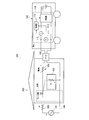
- FIG. 1 is a diagram showing a configuration of a charging system 100 according to an embodiment of the present invention.
- the house 150 is the home of the owner of the vehicle 160, for example.
- the house 150 is provided with a socket 105 connected to the in-vehicle charging device 170 of the vehicle 160.
- the house 150 includes a power supply circuit 180 that supplies a power supply current from the power supply 101.
- the house 150 is provided with a breaker panel 106 that shuts off the power supply circuit 180 when an overcurrent flows through the power supply circuit 180.
- the vehicle 160 charges the storage battery 115 mounted on the vehicle 160 by the in-vehicle charging device 170 connected to the socket 105 using the power supply 101 supplied from the power plant, for example, supplied from the power plant. To do.
- the vehicle 160 is an electric vehicle or the like that travels using the storage battery 115 as a drive source.
- the in-vehicle charging device 170 charges the storage battery 115 mounted on the vehicle 160. Details of the configuration of the in-vehicle charging device 170 will be described later.
- the power supply circuit 180 includes a power supply 101, an output impedance 102 of the power supply 101, and an impedance 104 of wiring connecting the power supply 101 and the charger 114.
- the power supply circuit 180 is a circuit for supplying power from the power supply 101 to the electrical device 103 or the in-vehicle charging device 170.
- the in-vehicle charging device 170 includes a voltage measuring unit 111, a current measuring unit 112, a control unit 113, and a charger 114.
- the voltage measurement unit 111 measures the input voltage of the charger 114 and outputs the voltage measurement value to the control unit 113.
- the current measuring unit 112 measures the input current of the charger 114 with respect to the input voltage of the charger 114 and outputs the measured current value to the control unit 113.
- the control unit 113 sets each relationship between the plurality of voltage measurement values input from the voltage measurement unit 111 and the plurality of current measurement values corresponding to the plurality of voltage measurement values input from the current measurement unit 112 as a primary approximate line.
- the obtained value is stored as a table.
- the control unit 113 controls the input current of the charger 114 according to the obtained first-order approximate straight line table. A method for obtaining a primary approximate line and a method for controlling the input current during charging will be described later.
- the charger 114 uses the power source 101 to charge the storage battery 115 with the input current controlled by the control unit 113.
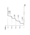
- FIG. 2 is a diagram showing the relationship between time and input current in a method for obtaining the relationship between input voltage and input current as a first-order approximation line.
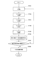
- FIG. 3 is a flowchart showing a method for obtaining a primary approximation line in the present embodiment.
- FIG. 4 is a diagram illustrating the relationship between the input voltage and the input current in the obtained primary approximate line.
- the control unit 113 obtains a primary approximate line, for example, before the start of charging.
- the control unit 113 sequentially changes the input current Ic at predetermined time intervals, and acquires a measured value of the input voltage Vc at each timing. For example, as shown in FIG. 2, the control unit 113 sequentially changes the input current Ic in the order of “0”, “1/4 Icmax”, “2/4 Icmax”, “3/4 Icmax”, “Icmax”, The measured value of the input voltage Vc is obtained. Then, the acquired input current Ic and input voltage Vc are associated with each other and stored as a table.
- control unit 113 acquires the input current Ic and the input voltage Vc in steps ST301 to ST304, and the relationship between the acquired input current Ic and the input voltage Vc is expressed as a linear approximation line using the least square method. Obtained (step ST306).
- control unit 113 determines whether or not the error of the least square method used when obtaining the linear approximation line is equal to or less than a certain value (step ST307).
- step ST307 determines the primary approximate straight line obtained in step ST306 (step ST308) and ends the process.
- step ST307 NO
- the control unit 113 repeats the processing of step ST301 to step ST306.
- control unit 113 obtains the relationship between the changed value of each input current Ic and the measured value of each input voltage Vc with respect to each input current Ic as a primary approximate line # 301 shown in FIG.
- the method of obtaining the linear approximation straight line # 301 is not limited to the least square method, and methods other than the least square method can be used.
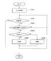
- FIG. 5 is a flowchart showing a method for controlling the input current of the charger 114 after the start of charging.
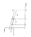
- FIG. 6 is a diagram illustrating control for reducing the input current of the charger 114 after the start of charging.
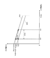
- FIG. 7 is a diagram illustrating control for increasing the input current of the charger 114 after the start of charging.
- Vc1 is the input voltage before the decrease
- Vc2 is the input voltage after the decrease
- Ic1 is the input current before the decrease
- Ic2 is the input current after the decrease.
- ⁇ Vcr is a voltage drop due to an increase in the load current Id flowing through the electrical device 103.
- ⁇ Icr is a current reduced by the control of the control unit 113.
- Vkr is the value of the input voltage Vc at the intersection of the primary approximate line # 301 and the vertical axis.
- Vc3 is the input voltage before the increase
- Vc4 is the input voltage after the increase
- Ic3 is the input current after the increase
- Ic4 is the input current before the increase.
- ⁇ Vcs is a voltage increase due to a decrease in the load current Id flowing through the electrical device 103.
- ⁇ Ics is a current increased by the control of the control unit 113.
- Vks is the value of the input voltage Vc at the intersection of the primary approximate straight line # 301 and the vertical axis.
- the control unit 113 controls the input current of the charger 114 using the first-order approximate straight line # 301 obtained in advance after the start of charging.
- control unit 113 acquires a measured value of the input voltage Vc from the voltage measuring unit 111 and also acquires a measured value of the input current Ic from the current measuring unit 112 (step ST501).
- control unit 113 determines whether or not charging is necessary (step ST502). For example, the control unit 113 determines that charging is unnecessary when the storage battery 115 is in a fully charged state, and determines that charging is required when the storage battery 115 is not in a fully charged state.
- step ST502 If it is determined that charging is not required (step ST502: NO), the control unit 113 ends the process.
- step ST502 determines whether or not the acquired measured value of the input voltage and measured value of the input current are on the primary approximate line # 301. Is determined (step ST503).
- step ST503 YES
- the current flowing through the power supply circuit 180 does not become an overcurrent even if the input current of the charger 114 is not adjusted. Therefore, the control part 113 returns to the process of step ST502.
- step ST503 determines whether or not the input voltage Vc is decreased (step ST504).
- step ST504 When the input voltage Vc is decreasing (step ST504: YES), the control unit 113 controls the charger 114 to reduce the input current Ic in accordance with the primary approximate line # 301 (step ST505).
- the range of the input voltage Vc substantially the same as the input voltage Vc1 is not less than the input voltage Vc1 and not more than a value larger than the input voltage Vc1 by a predetermined amount ⁇ (where ⁇ > 0) (Vc1 ⁇ Vc ⁇ (Vc1 + ⁇ )). It is. That is, the concept includes reducing the input current from Ic1 until the input current reaches a voltage that is higher by a predetermined amount ⁇ than the input voltage Vc1 before the decrease.
- step ST504 when the input voltage Vc has not decreased (step ST504: NO), the control unit 113 controls the charger 114 so as to increase the input current Ic (step ST506).
- the control unit 113 controls the charger 114 so that the input current increases from Ic4 so that the input voltage Vc3 before the increase is substantially the same as the input voltage Vc3 before the increase in the obtained control straight line # 701. However, at this time, the control unit 113 performs control so as not to exceed the maximum allowable current value Icmax.
- the range of the input voltage Vc substantially the same as the input voltage Vc3 is not less than the input voltage Vc3 and not less than a value smaller than the input voltage Vc3 by a predetermined amount ⁇ (where ⁇ > 0) (Vc3 ⁇ Vc ⁇ (Vc3- ⁇ ). )). That is, the concept includes increasing the input current from Ic4 until the input current becomes a voltage that is lower than the input voltage Vc3 before the increase by a predetermined amount ⁇ .
- step ST502 after performing the process of step ST502 for determining whether or not charging is necessary and determining that charging is necessary, the measurement value of the input voltage Vc is acquired from the voltage measuring unit 111, and You may make it perform the process of step ST501 which acquires the measured value of the input current Ic from the current measurement part 112.
- step ST501 which acquires the measured value of the input current Ic from the current measurement part 112.
- the voltage drop ⁇ Vc due to the start of the operation of the electric device 103 can be obtained by the equation (1).
- ⁇ Vc ⁇ ZP * ⁇ Id (1)
- Id the current flowing through the electrical device 103
- ZP the output impedance of the power
- the control unit 113 reduces the input current Ic to compensate for the influence due to the voltage drop ⁇ Vc obtained from the equation (1).
- Vc Vp ⁇ ZP (Ic + Id) ⁇ ZL * Ic (2)
- Vp the voltage Ic of the power supply 101
- ZP the output impedance ZL of the power supply 101
- Vc (Vp ⁇ ZP * Id) ⁇ ZS * Ic (3)
- Zs is the combined impedance of ZP and ZL
- Vk Vp-ZP * Id (4)
- Id the current flowing through the electrical device 103
- ZP the output impedance of the power supply 101
- equation (10) is obtained by substituting equation (1) into equation (9).
- ⁇ Id ⁇ (ZS / ZP) * ⁇ Ic (10)
- the relationship between the input voltage and the input current of the charger is obtained as a primary approximate line before the start of charging, and the input current of the charger is controlled according to the primary approximate line after the start of charging.
- the input current when the input voltage decreases due to the start of use of other electrical equipment during charging, the input current is reduced according to the decrease in input voltage, and When the input voltage rises due to the stop of use of the device, the input current is raised according to the rise of the input voltage, so that charging can be performed with the maximum input current that can be used for charging.
- control is performed to reduce or increase the input current of the charger 114 in one step.
- the present invention is not limited to this, and the control is performed so as to decrease or increase in multiple steps. May be.
- the primary approximation line is obtained before the start of charging, and the input current of the charger is controlled according to the primary approximation line after the start of charging. You may make it obtain
- the on-vehicle charging apparatus is suitable for charging a storage battery, which is a power source of a vehicle such as an electric vehicle, using a power source at home, for example.
Landscapes
- Engineering & Computer Science (AREA)
- Power Engineering (AREA)
- Transportation (AREA)
- Mechanical Engineering (AREA)
- Charge And Discharge Circuits For Batteries Or The Like (AREA)
- Electric Propulsion And Braking For Vehicles (AREA)
- Secondary Cells (AREA)
- Supply And Distribution Of Alternating Current (AREA)
Priority Applications (1)
| Application Number | Priority Date | Filing Date | Title |
|---|---|---|---|
| US14/005,860 US9174545B2 (en) | 2011-03-30 | 2012-03-28 | Vehicle charging device |
Applications Claiming Priority (2)
| Application Number | Priority Date | Filing Date | Title |
|---|---|---|---|
| JP2011-075791 | 2011-03-30 | ||
| JP2011075791A JP5001444B1 (ja) | 2011-03-30 | 2011-03-30 | 車載用充電装置 |
Publications (1)
| Publication Number | Publication Date |
|---|---|
| WO2012132430A1 true WO2012132430A1 (ja) | 2012-10-04 |
Family
ID=46793971
Family Applications (1)
| Application Number | Title | Priority Date | Filing Date |
|---|---|---|---|
| PCT/JP2012/002152 Ceased WO2012132430A1 (ja) | 2011-03-30 | 2012-03-28 | 車載用充電装置 |
Country Status (3)
| Country | Link |
|---|---|
| US (1) | US9174545B2 (enExample) |
| JP (2) | JP5001444B1 (enExample) |
| WO (1) | WO2012132430A1 (enExample) |
Families Citing this family (5)
| Publication number | Priority date | Publication date | Assignee | Title |
|---|---|---|---|---|
| US10545554B2 (en) * | 2010-11-10 | 2020-01-28 | Signify Holding B.V. | Resource metering system and method using such a system for smart energy consumption |
| CN104467121B (zh) * | 2014-12-31 | 2017-03-15 | 展讯通信(上海)有限公司 | 充电方法、装置、充电器、待充电设备及充电系统 |
| JP6490148B2 (ja) | 2017-06-12 | 2019-03-27 | 本田技研工業株式会社 | 充電制御装置 |
| JP2019062690A (ja) * | 2017-09-27 | 2019-04-18 | パナソニックIpマネジメント株式会社 | 充電装置および電子機器 |
| JP7544083B2 (ja) * | 2022-02-08 | 2024-09-03 | トヨタ自動車株式会社 | 車両 |
Citations (6)
| Publication number | Priority date | Publication date | Assignee | Title |
|---|---|---|---|---|
| JP2003092829A (ja) * | 2001-09-18 | 2003-03-28 | Hitachi Ltd | 電気機器システム |
| US20090254290A1 (en) * | 2008-04-03 | 2009-10-08 | Hyundai Motor Company | Method for estimating remaining capacity of battery |
| US20100244777A1 (en) * | 2009-03-30 | 2010-09-30 | Panasonic Ev Energy Co., Ltd. | Charging control method for secondary battery and battery charger |
| JP2011128010A (ja) * | 2009-12-17 | 2011-06-30 | Toshiba Corp | 二次電池装置および車両 |
| WO2012008392A1 (ja) * | 2010-07-15 | 2012-01-19 | トヨタ自動車株式会社 | 住宅用エネルギー管理システム |
| WO2012017985A1 (ja) * | 2010-08-04 | 2012-02-09 | 株式会社日立製作所 | 蓄電池制御装置、充電スタンド及び蓄電池制御方法 |
Family Cites Families (7)
| Publication number | Priority date | Publication date | Assignee | Title |
|---|---|---|---|---|
| US6590370B1 (en) * | 2002-10-01 | 2003-07-08 | Mti Microfuel Cells Inc. | Switching DC-DC power converter and battery charger for use with direct oxidation fuel cell power source |
| JP2008141924A (ja) * | 2006-12-05 | 2008-06-19 | Hitachi Ltd | 車載電池充電装置、車載電池装置及び車載電池充電方法 |
| EP1965481A2 (en) * | 2007-02-28 | 2008-09-03 | STMicroelectronics, Inc. | Integrated circuit and method for monitoring and controlling power and for detecting open load state |
| JP4905728B2 (ja) * | 2008-07-29 | 2012-03-28 | 三菱自動車工業株式会社 | 発電制御装置 |
| JP2010088150A (ja) * | 2008-09-29 | 2010-04-15 | Tdk Corp | 充電装置 |
| JP2010200530A (ja) * | 2009-02-26 | 2010-09-09 | Omron Corp | 充電制御装置および方法、充電装置および方法、並びに、プログラム |
| JP2011017619A (ja) * | 2009-07-09 | 2011-01-27 | Mitsumi Electric Co Ltd | 電池パック、半導体装置、携帯機器、通知方法、通知プログラム |
-
2011
- 2011-03-30 JP JP2011075791A patent/JP5001444B1/ja not_active Expired - Fee Related
-
2012
- 2012-03-28 US US14/005,860 patent/US9174545B2/en not_active Expired - Fee Related
- 2012-03-28 WO PCT/JP2012/002152 patent/WO2012132430A1/ja not_active Ceased
- 2012-05-16 JP JP2012112220A patent/JP5657602B2/ja not_active Expired - Fee Related
Patent Citations (6)
| Publication number | Priority date | Publication date | Assignee | Title |
|---|---|---|---|---|
| JP2003092829A (ja) * | 2001-09-18 | 2003-03-28 | Hitachi Ltd | 電気機器システム |
| US20090254290A1 (en) * | 2008-04-03 | 2009-10-08 | Hyundai Motor Company | Method for estimating remaining capacity of battery |
| US20100244777A1 (en) * | 2009-03-30 | 2010-09-30 | Panasonic Ev Energy Co., Ltd. | Charging control method for secondary battery and battery charger |
| JP2011128010A (ja) * | 2009-12-17 | 2011-06-30 | Toshiba Corp | 二次電池装置および車両 |
| WO2012008392A1 (ja) * | 2010-07-15 | 2012-01-19 | トヨタ自動車株式会社 | 住宅用エネルギー管理システム |
| WO2012017985A1 (ja) * | 2010-08-04 | 2012-02-09 | 株式会社日立製作所 | 蓄電池制御装置、充電スタンド及び蓄電池制御方法 |
Also Published As
| Publication number | Publication date |
|---|---|
| JP5657602B2 (ja) | 2015-01-21 |
| US9174545B2 (en) | 2015-11-03 |
| JP2012210131A (ja) | 2012-10-25 |
| JP5001444B1 (ja) | 2012-08-15 |
| JP2012213319A (ja) | 2012-11-01 |
| US20140009114A1 (en) | 2014-01-09 |
Similar Documents
| Publication | Publication Date | Title |
|---|---|---|
| JP5455705B2 (ja) | 充電装置と充電方法 | |
| JP5682433B2 (ja) | 充電制御システム | |
| KR102655397B1 (ko) | 배터리 관리 장치 및 시스템 | |
| WO2019155751A1 (ja) | 車載充電装置、及び車載充電装置の制御方法 | |
| KR102359911B1 (ko) | 전기 차량 충전 시스템 및 전기 차량 충전 방법 | |
| EP3373406A1 (en) | Charging control device | |
| JP2015171219A (ja) | 電源システム | |
| CN112106288B (zh) | 电力变换装置以及电力变换系统 | |
| JP5657602B2 (ja) | 車載用充電装置 | |
| JP5942171B2 (ja) | 車載用充電装置 | |
| KR101871020B1 (ko) | 태양광 인버터를 이용한 에너지 저장 장치의 배터리 충전 시스템 | |
| US20180145378A1 (en) | Power Storage Device and Connection Control | |
| WO2015162877A1 (ja) | リチウムイオン二次電池システム及びリチウム二次電池システムの運転方法 | |
| CN113228454A (zh) | 系统互连装置及服务器 | |
| KR102160493B1 (ko) | 전기자동차 충전 장치 및 충전 방법 | |
| US8704496B2 (en) | Charge control system | |
| CN113541496B (zh) | 电力转换装置 | |
| JP7071229B2 (ja) | 電源システム | |
| KR102936485B1 (ko) | 배터리 피드백 제어 기능이 있는 병렬 충전기 회로 | |
| KR101927670B1 (ko) | 충전 모드 자동 변경 무선 충전 장치 및 방법 | |
| JP2023027996A (ja) | 電源制御装置、電源装置、及び電源制御方法 | |
| JP2020078185A (ja) | 車両 | |
| JP2023110252A (ja) | 電力供給設備 | |
| JP2019106771A (ja) | 車載充電システム | |
| JP2017108506A (ja) | 双方向dc−dcコンバータの並列運転装置 |
Legal Events
| Date | Code | Title | Description |
|---|---|---|---|
| 121 | Ep: the epo has been informed by wipo that ep was designated in this application |
Ref document number: 12765157 Country of ref document: EP Kind code of ref document: A1 |
|
| WWE | Wipo information: entry into national phase |
Ref document number: 14005860 Country of ref document: US |
|
| NENP | Non-entry into the national phase |
Ref country code: DE |
|
| 122 | Ep: pct application non-entry in european phase |
Ref document number: 12765157 Country of ref document: EP Kind code of ref document: A1 |