WO2012132005A1 - ハニカム構造体 - Google Patents
ハニカム構造体 Download PDFInfo
- Publication number
- WO2012132005A1 WO2012132005A1 PCT/JP2011/058334 JP2011058334W WO2012132005A1 WO 2012132005 A1 WO2012132005 A1 WO 2012132005A1 JP 2011058334 W JP2011058334 W JP 2011058334W WO 2012132005 A1 WO2012132005 A1 WO 2012132005A1
- Authority
- WO
- WIPO (PCT)
- Prior art keywords
- honeycomb fired
- fired body
- honeycomb
- cell
- heat capacity
- Prior art date
Links
Images


Classifications
-
- B—PERFORMING OPERATIONS; TRANSPORTING
- B01—PHYSICAL OR CHEMICAL PROCESSES OR APPARATUS IN GENERAL
- B01D—SEPARATION
- B01D46/00—Filters or filtering processes specially modified for separating dispersed particles from gases or vapours
- B01D46/24—Particle separators, e.g. dust precipitators, using rigid hollow filter bodies
- B01D46/2403—Particle separators, e.g. dust precipitators, using rigid hollow filter bodies characterised by the physical shape or structure of the filtering element
- B01D46/2418—Honeycomb filters
- B01D46/2425—Honeycomb filters characterized by parameters related to the physical properties of the honeycomb structure material
- B01D46/2429—Honeycomb filters characterized by parameters related to the physical properties of the honeycomb structure material of the honeycomb walls or cells
-
- B—PERFORMING OPERATIONS; TRANSPORTING
- B01—PHYSICAL OR CHEMICAL PROCESSES OR APPARATUS IN GENERAL
- B01D—SEPARATION
- B01D46/00—Filters or filtering processes specially modified for separating dispersed particles from gases or vapours
- B01D46/24—Particle separators, e.g. dust precipitators, using rigid hollow filter bodies
- B01D46/2403—Particle separators, e.g. dust precipitators, using rigid hollow filter bodies characterised by the physical shape or structure of the filtering element
- B01D46/2418—Honeycomb filters
- B01D46/2425—Honeycomb filters characterized by parameters related to the physical properties of the honeycomb structure material
- B01D46/24494—Thermal expansion coefficient, heat capacity or thermal conductivity
-
- B—PERFORMING OPERATIONS; TRANSPORTING
- B01—PHYSICAL OR CHEMICAL PROCESSES OR APPARATUS IN GENERAL
- B01D—SEPARATION
- B01D46/00—Filters or filtering processes specially modified for separating dispersed particles from gases or vapours
- B01D46/24—Particle separators, e.g. dust precipitators, using rigid hollow filter bodies
- B01D46/2403—Particle separators, e.g. dust precipitators, using rigid hollow filter bodies characterised by the physical shape or structure of the filtering element
- B01D46/2418—Honeycomb filters
- B01D46/2451—Honeycomb filters characterized by the geometrical structure, shape, pattern or configuration or parameters related to the geometry of the structure
- B01D46/247—Honeycomb filters characterized by the geometrical structure, shape, pattern or configuration or parameters related to the geometry of the structure of the cells
-
- B—PERFORMING OPERATIONS; TRANSPORTING
- B01—PHYSICAL OR CHEMICAL PROCESSES OR APPARATUS IN GENERAL
- B01D—SEPARATION
- B01D46/00—Filters or filtering processes specially modified for separating dispersed particles from gases or vapours
- B01D46/24—Particle separators, e.g. dust precipitators, using rigid hollow filter bodies
- B01D46/2403—Particle separators, e.g. dust precipitators, using rigid hollow filter bodies characterised by the physical shape or structure of the filtering element
- B01D46/2418—Honeycomb filters
- B01D46/2451—Honeycomb filters characterized by the geometrical structure, shape, pattern or configuration or parameters related to the geometry of the structure
- B01D46/2474—Honeycomb filters characterized by the geometrical structure, shape, pattern or configuration or parameters related to the geometry of the structure of the walls along the length of the honeycomb
-
- B—PERFORMING OPERATIONS; TRANSPORTING
- B01—PHYSICAL OR CHEMICAL PROCESSES OR APPARATUS IN GENERAL
- B01D—SEPARATION
- B01D46/00—Filters or filtering processes specially modified for separating dispersed particles from gases or vapours
- B01D46/24—Particle separators, e.g. dust precipitators, using rigid hollow filter bodies
- B01D46/2403—Particle separators, e.g. dust precipitators, using rigid hollow filter bodies characterised by the physical shape or structure of the filtering element
- B01D46/2418—Honeycomb filters
- B01D46/2451—Honeycomb filters characterized by the geometrical structure, shape, pattern or configuration or parameters related to the geometry of the structure
- B01D46/2478—Structures comprising honeycomb segments
-
- B—PERFORMING OPERATIONS; TRANSPORTING
- B01—PHYSICAL OR CHEMICAL PROCESSES OR APPARATUS IN GENERAL
- B01D—SEPARATION
- B01D46/00—Filters or filtering processes specially modified for separating dispersed particles from gases or vapours
- B01D46/24—Particle separators, e.g. dust precipitators, using rigid hollow filter bodies
- B01D46/2403—Particle separators, e.g. dust precipitators, using rigid hollow filter bodies characterised by the physical shape or structure of the filtering element
- B01D46/2418—Honeycomb filters
- B01D46/2451—Honeycomb filters characterized by the geometrical structure, shape, pattern or configuration or parameters related to the geometry of the structure
- B01D46/2482—Thickness, height, width, length or diameter
-
- B—PERFORMING OPERATIONS; TRANSPORTING
- B01—PHYSICAL OR CHEMICAL PROCESSES OR APPARATUS IN GENERAL
- B01D—SEPARATION
- B01D46/00—Filters or filtering processes specially modified for separating dispersed particles from gases or vapours
- B01D46/24—Particle separators, e.g. dust precipitators, using rigid hollow filter bodies
- B01D46/2403—Particle separators, e.g. dust precipitators, using rigid hollow filter bodies characterised by the physical shape or structure of the filtering element
- B01D46/2418—Honeycomb filters
- B01D46/2451—Honeycomb filters characterized by the geometrical structure, shape, pattern or configuration or parameters related to the geometry of the structure
- B01D46/2484—Cell density, area or aspect ratio
-
- B—PERFORMING OPERATIONS; TRANSPORTING
- B01—PHYSICAL OR CHEMICAL PROCESSES OR APPARATUS IN GENERAL
- B01D—SEPARATION
- B01D46/00—Filters or filtering processes specially modified for separating dispersed particles from gases or vapours
- B01D46/24—Particle separators, e.g. dust precipitators, using rigid hollow filter bodies
- B01D46/2403—Particle separators, e.g. dust precipitators, using rigid hollow filter bodies characterised by the physical shape or structure of the filtering element
- B01D46/2418—Honeycomb filters
- B01D46/2451—Honeycomb filters characterized by the geometrical structure, shape, pattern or configuration or parameters related to the geometry of the structure
- B01D46/2486—Honeycomb filters characterized by the geometrical structure, shape, pattern or configuration or parameters related to the geometry of the structure characterised by the shapes or configurations
- B01D46/249—Quadrangular e.g. square or diamond
-
- B—PERFORMING OPERATIONS; TRANSPORTING
- B01—PHYSICAL OR CHEMICAL PROCESSES OR APPARATUS IN GENERAL
- B01D—SEPARATION
- B01D46/00—Filters or filtering processes specially modified for separating dispersed particles from gases or vapours
- B01D46/24—Particle separators, e.g. dust precipitators, using rigid hollow filter bodies
- B01D46/2403—Particle separators, e.g. dust precipitators, using rigid hollow filter bodies characterised by the physical shape or structure of the filtering element
- B01D46/2418—Honeycomb filters
- B01D46/2451—Honeycomb filters characterized by the geometrical structure, shape, pattern or configuration or parameters related to the geometry of the structure
- B01D46/2486—Honeycomb filters characterized by the geometrical structure, shape, pattern or configuration or parameters related to the geometry of the structure characterised by the shapes or configurations
- B01D46/2494—Octagonal
-
- B—PERFORMING OPERATIONS; TRANSPORTING
- B01—PHYSICAL OR CHEMICAL PROCESSES OR APPARATUS IN GENERAL
- B01D—SEPARATION
- B01D46/00—Filters or filtering processes specially modified for separating dispersed particles from gases or vapours
- B01D46/24—Particle separators, e.g. dust precipitators, using rigid hollow filter bodies
- B01D46/2403—Particle separators, e.g. dust precipitators, using rigid hollow filter bodies characterised by the physical shape or structure of the filtering element
- B01D46/2418—Honeycomb filters
- B01D46/2498—The honeycomb filter being defined by mathematical relationships
-
- B—PERFORMING OPERATIONS; TRANSPORTING
- B01—PHYSICAL OR CHEMICAL PROCESSES OR APPARATUS IN GENERAL
- B01D—SEPARATION
- B01D46/00—Filters or filtering processes specially modified for separating dispersed particles from gases or vapours
- B01D46/24—Particle separators, e.g. dust precipitators, using rigid hollow filter bodies
- B01D46/2403—Particle separators, e.g. dust precipitators, using rigid hollow filter bodies characterised by the physical shape or structure of the filtering element
- B01D46/2418—Honeycomb filters
- B01D46/2451—Honeycomb filters characterized by the geometrical structure, shape, pattern or configuration or parameters related to the geometry of the structure
- B01D46/2455—Honeycomb filters characterized by the geometrical structure, shape, pattern or configuration or parameters related to the geometry of the structure of the whole honeycomb or segments
-
- Y—GENERAL TAGGING OF NEW TECHNOLOGICAL DEVELOPMENTS; GENERAL TAGGING OF CROSS-SECTIONAL TECHNOLOGIES SPANNING OVER SEVERAL SECTIONS OF THE IPC; TECHNICAL SUBJECTS COVERED BY FORMER USPC CROSS-REFERENCE ART COLLECTIONS [XRACs] AND DIGESTS
- Y10—TECHNICAL SUBJECTS COVERED BY FORMER USPC
- Y10T—TECHNICAL SUBJECTS COVERED BY FORMER US CLASSIFICATION
- Y10T428/00—Stock material or miscellaneous articles
- Y10T428/24—Structurally defined web or sheet [e.g., overall dimension, etc.]
- Y10T428/24149—Honeycomb-like
Definitions
- the present invention relates to a honeycomb structure.
- Particulates such as soot (hereinafter also referred to as PM) and other harmful components contained in exhaust gas discharged from internal combustion engines such as vehicles such as buses and trucks or construction machinery may cause harm to the environment and the human body. It has become a problem recently.
- honeycomb filters for purifying exhaust gas.
- Conventionally known as such a honeycomb structure is a honeycomb structure formed of a ceramic block in which a plurality of honeycomb fired bodies in which a large number of cells are arranged in parallel in the longitudinal direction with a cell wall interposed therebetween.
- a sudden temperature change or local heat generation of the exhaust gas tends to cause uneven temperature distribution inside the honeycomb structure, and as a result, cracks due to thermal stress occur. Problems occur.
- the honeycomb structure when the honeycomb structure is used for collecting PM in exhaust gas, the honeycomb structure needs to be regenerated in order to burn and remove the collected PM. In the regeneration process, there is a problem that cracks are likely to occur because large thermal stress is likely to occur with the combustion of PM.
- Patent Document 1 discloses a honeycomb fired body in which the heat capacity per unit volume in the outer peripheral portion of the honeycomb fired body is larger than the heat capacity per unit volume in the central part of the honeycomb fired body in order to enhance durability against cracks due to thermal stress.
- a honeycomb structure including: Specifically, Patent Document 1 discloses a honeycomb structure including a honeycomb fired body in which the average thickness of the cell walls in the outer peripheral portion of the honeycomb fired body is larger than the average thickness of the cell walls in the center of the honeycomb fired body. It is disclosed.
- the present invention has been made to solve the above problems, and an object of the present invention is to provide a honeycomb structure in which cracks are unlikely to occur when the honeycomb structure becomes high temperature.
- honeycomb structure comprising a ceramic block in which a large number of cells are arranged side by side in the longitudinal direction across a cell wall, and a plurality of honeycomb fired bodies each having an outer peripheral wall formed on the outer periphery are bound via an adhesive layer, At least one of the plurality of honeycomb fired bodies has a central high heat capacity type honeycomb fired in which the heat capacity per unit volume in the central portion of the honeycomb fired body is larger than the heat capacity per unit volume in the outer peripheral portion of the honeycomb fired body. It is a body.
- the honeycomb structure according to claim 1 includes a central high heat capacity type honeycomb fired body in which the heat capacity per unit volume in the central part of the honeycomb fired body is larger than the heat capacity per unit volume in the outer peripheral part of the honeycomb fired body. Yes. Therefore, when the honeycomb structure has a high temperature, the temperature hardly rises at the center of the central high heat capacity honeycomb fired body. On the other hand, the temperature tends to rise at the outer peripheral portion of the central high heat capacity type honeycomb fired body, but the periphery of the high heat capacity type honeycomb fired body (in the case where an adhesive layer or an outer peripheral coat layer is formed, an outer peripheral coat). Heat can be released to the layer).
- the temperature difference generated between the central portion and the outer peripheral portion of the central high heat capacity type honeycomb fired body can be suppressed, the temperature difference between the central portion and the outer peripheral portion of the central high heat capacity type honeycomb fired body can be reduced. It is possible to prevent the occurrence of cracks. As a result, cracks are less likely to occur in the honeycomb structure.
- the cell wall of the honeycomb fired body refers to a portion that exists between two adjacent cells and separates the two cells.
- the outer peripheral wall of the honeycomb fired body refers to a portion that exists on the outer periphery of the honeycomb fired body and constitutes the outer periphery of the honeycomb fired body.
- the center portion of the honeycomb fired body includes a cross section perpendicular to the longitudinal direction of the honeycomb fired body including the center on the cross section of the honeycomb fired body, and is similar to the outer periphery on the cross section of the honeycomb fired body. It is a portion surrounded by and occupies 50% of the cross-sectional area of the honeycomb fired body.
- the outer peripheral portion of the honeycomb fired body is a portion located outside the central portion of the honeycomb fired body and means a portion other than the central portion and the outer peripheral wall of the honeycomb fired body.
- the heat capacity per unit volume refers to the heat capacity based on the volume including the cell.
- an average thickness of the cell wall in the central portion of the central high heat capacity type honeycomb fired body is an average thickness of the cell wall in the outer peripheral portion of the central high heat capacity type honeycomb fired body. Thicker than that.
- the honeycomb structure according to claim 2 when used for collecting PM in the exhaust gas, it is desirable also from the following points. In the portion where the cell wall thickness of the honeycomb fired body is thin, the pressure loss is relatively small. In the honeycomb structure according to claim 2, since the average thickness of the cell wall in the outer peripheral portion of the central high heat capacity type honeycomb fired body is thinner than the average thickness of the cell wall in the central portion of the central high heat capacity type honeycomb fired body. The exhaust gas easily flows to the outer peripheral portion of the central high heat capacity honeycomb fired body. As a result, PM is more easily deposited on the outer peripheral portion of the central high heat capacity type honeycomb fired body than in the central portion of the central high heat capacity type honeycomb fired body.
- the honeycomb structure according to claim 2 when the PM is burned during the regeneration process, the heat generation at the center of the central high heat capacity type honeycomb fired body is relatively small. can do.
- the amount of PM deposited is large, so the amount of heat generated is relatively large, and the heat capacity is also small, so the temperature of the outer peripheral part of the central high heat capacity type honeycomb fired body is small. Tends to rise.
- an average thickness of the cell wall in the central portion of the central high heat capacity type honeycomb fired body is 0.10 to 0.20 mm, and the central high heat capacity type honeycomb fired body.
- the average thickness of the cell wall in the outer peripheral portion of the body is 90 to 98% of the average thickness of the cell wall in the central portion of the central high heat capacity honeycomb fired body. If the average thickness of the cell wall in the central part of the central high heat capacity type honeycomb fired body is less than 0.10 mm, the heat capacity per unit volume in the central part of the central high heat capacity type honeycomb fired body becomes too small. It becomes difficult to prevent a temperature rise at the center of the capacitive honeycomb fired body.
- the honeycomb structure becomes high temperature, cracks are likely to occur in the honeycomb structure.
- the average cell wall thickness at the center of the central high heat capacity honeycomb fired body is less than 0.10 mm, the average cell wall thickness at the outer periphery of the central high heat capacity honeycomb fired body is less than 0.10 mm. Since it becomes small, it becomes difficult to ensure the strength of the honeycomb fired body.
- the average thickness of the cell wall in the central part of the central high heat capacity type honeycomb fired body exceeds 0.20 mm, the heat capacity per unit volume in the central part of the central high heat capacity type honeycomb fired body increases. The effect of preventing the temperature rise at the center of the capacitive honeycomb fired body is increased.
- the difference in the average thickness of the cell wall between the center portion and the outer peripheral portion of the fired body is reduced. Accordingly, since the difference in heat capacity per unit volume between the central portion and the outer peripheral portion of the central high heat capacity type honeycomb fired body is reduced, the temperature difference between the central portion and the outer peripheral portion of the central high heat capacity type honeycomb fired body is reduced. It is difficult to obtain the effect.
- the thickness of the cell wall gradually decreases from the central portion of the central high heat capacity type honeycomb fired body toward the outer peripheral portion.
- the thickness of the cell wall continuously decreases from the central portion of the central high heat capacity type honeycomb fired body toward the outer peripheral portion.
- the heat capacity per unit volume of the central high heat capacity type honeycomb fired body is stepwise or continuous from the central part to the outer peripheral part of the central high heat capacity type honeycomb fired body. Can be reduced. Therefore, heat can be smoothly transferred from the central portion of the central high heat capacity type honeycomb fired body toward the outer peripheral portion.
- the cell wall thickness decreases stepwise means that the cell wall thickness is 2 when the relationship between the cell wall thickness and the length perpendicular to the thickness direction is plotted. It means to decrease discontinuously in a step-like manner.
- cell wall thickness decreases continuously means that when the relationship between the cell wall thickness and the length perpendicular to the thickness direction is plotted, the cell wall thickness is curved or linear. It means to decrease.
- the thickness of the cell wall located on the outermost side of the central high heat capacity type honeycomb fired body is other than the cell wall located on the outermost side of the central high heat capacity type honeycomb fired body. It is thinner than the cell wall thickness.
- the heat capacity per unit volume in the outermost portion of the central high heat capacity type honeycomb fired body can be made smaller than the heat capacity per unit volume in the other portions. Therefore, the outermost temperature of the central high heat capacity honeycomb fired body tends to increase. Even in the honeycomb structure including the central high heat capacity type honeycomb fired body having such a configuration, the temperature difference between the central portion and the outer peripheral portion of the central high heat capacity type honeycomb fired body can be further reduced. Generation of cracks can be prevented.
- the thickness of the outer peripheral wall is 0.20 to 0.50 mm.
- the thickness of the outer peripheral wall of the honeycomb fired body is less than 0.20 mm, it becomes difficult to ensure the strength of the honeycomb fired body.
- the thickness of the outer peripheral wall of the honeycomb fired body exceeds 0.50 mm, the weight of the entire honeycomb structure for which weight reduction is desired increases.
- the plurality of cells include large-capacity cells and small-capacity cells, and are perpendicular to the longitudinal direction of the large-capacity cells.
- the area of such a cross section is larger than the area of the cross section perpendicular to the longitudinal direction of the small capacity cell.
- the shape of the cross section perpendicular to the longitudinal direction of the large capacity cell is an octagon
- the shape of the cross section perpendicular to the longitudinal direction of the small capacity cell is a quadrangle.
- the shape of the cross section perpendicular to the longitudinal direction of the large capacity cell is a quadrangle
- the shape of the cross section perpendicular to the longitudinal direction of the small capacity cell is a quadrangle
- the shape of the cell wall forming the large capacity cell and the small capacity cell is curved. It is configured.
- the honeycomb structure according to any one of claims 8 to 11 When the honeycomb structure according to any one of claims 8 to 11 is used for collecting PM in exhaust gas, a large amount of PM can be collected in a large-capacity cell. Therefore, the temperature of the honeycomb fired body is likely to rise when PM is burned during the regeneration process. However, in the honeycomb structure according to any one of claims 8 to 11, since the temperature difference between the central portion and the outer peripheral portion of the central high heat capacity type honeycomb fired body can be reduced, generation of cracks is prevented. can do.
- the isostatic strength and the compressive strength of the honeycomb fired body can be increased by increasing the symmetry of the cross-sectional shape of the large-capacity cell and the cross-sectional shape of the small-capacity cell. Can be improved. Therefore, when the honeycomb structure becomes high temperature, it is possible to prevent cracks from occurring in the honeycomb structure from the viewpoint of strength.
- the honeycomb structure according to any one of claims 9 to 11 is used for collecting PM in the exhaust gas, by increasing the symmetry between the large capacity cell and the small capacity cell, Exhaust gas can be allowed to flow evenly.
- an area ratio of an area of the cross section perpendicular to the longitudinal direction of the large capacity cell to an area of a cross section perpendicular to the longitudinal direction of the small capacity cell is 1.4 to 2 .8.
- the area ratio is less than 1.4, the difference between the cross-sectional area of the large-capacity cell and the cross-sectional area of the small-capacity cell is small, so that it is difficult to obtain the effect of providing the large-capacity cell and the small-capacity cell.
- the area ratio exceeds 2.8, the ratio of the cell walls separating large capacity cells increases.
- the honeycomb structure according to claim 12 is used to collect PM in the exhaust gas, the exhaust gas hardly passes through the cell walls separating the large-capacity cells. The pressure loss, which is the required performance, increases.
- honeycomb fired bodies that do not constitute the outer periphery of the ceramic block are the central high heat capacity type honeycomb fired bodies.
- the honeycomb fired body located in the center portion of the honeycomb structure is all centered. Since the honeycomb fired body has a high heat capacity, the temperature difference between the central portion and the outer peripheral portion of the central high heat capacity honeycomb fired body can be reduced. Therefore, it is possible to prevent cracks from occurring in the honeycomb structure.
- the plurality of honeycomb fired bodies are all the central high heat capacity type honeycomb fired bodies.
- the center high heat capacity type honeycomb fired body is disposed between the central portion and the outer peripheral portion. The temperature difference can be reduced. Therefore, the temperature of the entire honeycomb structure can be made uniform. Accordingly, it is possible to further prevent cracks from occurring in the honeycomb structure.
- honeycomb structure according to claim 15 in each of the plurality of honeycomb fired bodies, one end of each of the plurality of cells is alternately sealed.
- the honeycomb structure according to the fifteenth aspect can be suitably used as a filter for collecting PM in exhaust gas.
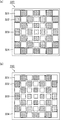
- FIG. 1 (a) is a perspective view which shows typically an example of the honeycomb structure which concerns on 1st embodiment of this invention.
- FIG. 1 (b) is a cross-sectional view taken along line AA of the honeycomb structure shown in FIG. 1 (a).
- FIG. 2A is a perspective view schematically showing an example of an inner honeycomb fired body constituting the honeycomb structure according to the first embodiment of the present invention.
- FIG. 2B is a cross-sectional view of the inner honeycomb fired body shown in FIG. 2A taken along line BB.
- FIG. 3 is a cross-sectional view schematically showing the central portion and the outer peripheral portion of the honeycomb fired body constituting the honeycomb structure according to the embodiment of the present invention.
- FIG. 1 (b) is a cross-sectional view taken along line AA of the honeycomb structure shown in FIG. 1 (a).
- FIG. 2A is a perspective view schematically showing an example of an inner honeycomb fired body constituting the honeycomb structure according to the first embodiment of the present
- FIGS. 4 is a side view of the inner honeycomb fired body shown in FIGS. 2 (a) and 2 (b).
- FIGS. 5A and 5B are side views schematically showing an example of the outer honeycomb fired body constituting the honeycomb structure according to the first embodiment of the present invention.
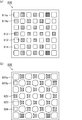
- Fig.6 (a) is a side view which shows typically an example of the inner side honeycomb fired body which comprises the honeycomb structure which concerns on 2nd embodiment of this invention from one end surface side.
- Fig. 6 (b) is a side view schematically showing the inner honeycomb fired body shown in Fig. 6 (a) from the other end face side.
- FIG. 7 is a side view schematically showing another example of the inner honeycomb fired body constituting the honeycomb structure according to the second embodiment of the present invention.
- FIG. 1 is a side view which shows typically an example of the inner side honeycomb fired body which comprises the honeycomb structure which concerns on 2nd embodiment of this invention from one end surface side.
- Fig. 6 (b) is a side view
- FIG. 8 is a side view schematically showing still another example of the inner honeycomb fired body constituting the honeycomb structure according to the second embodiment of the present invention.
- FIG. 9 is a side view schematically showing an example of the inner honeycomb fired body constituting the honeycomb structure according to the third embodiment of the present invention.
- FIG. 10A and FIG. 10B are side views schematically showing another example of the inner honeycomb fired body constituting the honeycomb structure according to the third embodiment of the present invention.
- FIG. 11 is a side view schematically showing an example of an inner honeycomb fired body constituting the honeycomb structure according to the fourth embodiment of the present invention.
- FIG. 12 is a side view schematically showing another example of the inner honeycomb fired body constituting the honeycomb structure according to the fourth embodiment of the present invention.
- FIG. 13 is a schematic diagram for explaining a method for measuring the cell wall thickness of the honeycomb fired bodies according to the examples and the comparative examples.
- FIG. 14A and FIG. 14B are side views schematically showing an example of an outer honeycomb fired body constituting a honeycomb structure according to another embodiment of the present invention.
- Fig. 15 (a) is a side view schematically showing another example of the inner honeycomb fired body constituting the honeycomb structure according to the first embodiment of the present invention.
- Fig. 15 (b) is a side view schematically showing another example of the inner honeycomb fired body constituting the honeycomb structure according to the second embodiment of the present invention.
- FIG. 16 (a) and 16 (b) are side views schematically showing an example of an inner honeycomb fired body constituting a honeycomb structure according to another embodiment of the present invention.
- FIG. 17 is a perspective view schematically showing an example of a honeycomb structure according to another embodiment of the present invention.
- the present inventors examined the cause of the occurrence of cracks in the conventional honeycomb structure described in Patent Document 1.
- a temperature difference is likely to occur between the central portion and the outer peripheral portion of the honeycomb fired body constituting the honeycomb structure. It was found that cracks occurred.
- the heat capacity per unit volume in the central part of the honeycomb fired body is smaller than the heat capacity per unit volume in the outer peripheral part of the honeycomb fired body. For this reason, when the honeycomb structure has a high temperature, the temperature of the central portion of the honeycomb fired body immediately rises, whereas the temperature of the outer peripheral portion of the honeycomb fired body hardly rises.
- honeycomb structure comprising a ceramic block in which a large number of cells are arranged side by side in the longitudinal direction across a cell wall, and a plurality of honeycomb fired bodies each having an outer peripheral wall formed on the outer periphery are bound via an adhesive layer, At least one of the plurality of honeycomb fired bodies has a central high heat capacity type honeycomb fired in which the heat capacity per unit volume in the central portion of the honeycomb fired body is larger than the heat capacity per unit volume in the outer peripheral portion of the honeycomb fired body. It is a body.
- all the honeycomb fired bodies that do not constitute the outer periphery of the ceramic block are the above-described central high heat capacity honeycomb fired bodies.
- the honeycomb fired body located at the position constituting the outer periphery of the ceramic block is also referred to as “outer honeycomb fired body”, and the honeycomb fired body positioned inside the outer honeycomb fired body is also referred to as “inner honeycomb fired body”. To do.
- the honeycomb fired body and the inner honeycomb fired body they are simply referred to as a honeycomb fired body.
- the section perpendicular to the longitudinal direction of the honeycomb structure refers to a cross section perpendicular to the longitudinal direction or a cross section perpendicular to the longitudinal direction of the honeycomb formed body.
- the cross-sectional area of the honeycomb fired body it refers to the area of the cross section perpendicular to the longitudinal direction of the honeycomb fired body.
- FIG. 1 (a) is a perspective view which shows typically an example of the honeycomb structure which concerns on 1st embodiment of this invention.
- FIG. 1 (b) is a cross-sectional view taken along line AA of the honeycomb structure shown in FIG. 1 (a).
- a plurality of honeycomb fired bodies 110, 120, and 130 are bonded together through the adhesive layer 11 to form a ceramic block 13
- An outer peripheral coat layer 12 is formed on the outer periphery of the ceramic block 13.
- the outer periphery coating layer should just be formed as needed.
- the honeycomb fired bodies 110, 120, and 130 that constitute the honeycomb structure 10 will be described later, but are preferably porous bodies made of silicon carbide or silicon-bonded silicon carbide.
- honeycomb structure 10 shown in FIGS. 1 (a) and 1 (b), eight outer honeycomb fired bodies 120 and eight outer honeycomb fired bodies 130 at positions constituting the outer periphery of the ceramic block 13 are provided.
- the sixteen inner honeycomb fired bodies 110 positioned inside the honeycomb fired bodies 120 and 130 are arranged via the adhesive layer 11 so that the cross-sectional shape of the ceramic block 13 (honeycomb structure 10) is circular. They are united.
- the cross-sectional shape of the inner honeycomb fired body 110 is a quadrangle (square).
- the cross section of the outer honeycomb fired body 120 has a shape surrounded by three line segments and one arc. Two angles formed by two of the three line segments are both 90 °.
- the cross section of the outer honeycomb fired body 130 has a shape surrounded by two line segments and one arc. The angle formed by these two line segments is 90 °.
- FIG. 2A is a perspective view schematically showing an example of an inner honeycomb fired body constituting the honeycomb structure according to the first embodiment of the present invention.
- FIG. 2B is a cross-sectional view of the inner honeycomb fired body shown in FIG. 2A taken along line BB.
- a large number of cells 111 are arranged in the longitudinal direction (in the direction of arrow a in FIG. 2 (a)) with the cell walls 113 therebetween. And an outer peripheral wall 114 is formed on the outer periphery thereof.
- One end of the cell 111 is sealed with a sealing material 112. Accordingly, the exhaust gas G (in FIG. 2B, the exhaust gas is indicated by G and the flow of the exhaust gas is indicated by an arrow in FIG. 2B) always passes through the cell wall 113 separating the cells 111. Then, the other end surface flows out from the other cell 111 opened.
- exhaust gas G passes through the cell wall 113, PM and the like in the exhaust gas are collected, so that the cell wall 113 functions as a filter.
- the honeycomb fired bodies that do not constitute the outer periphery of the ceramic block (that is, the inner honeycomb fired bodies) all have a heat capacity per unit volume at the center of the honeycomb fired body.
- a central high heat capacity type honeycomb fired body having a larger heat capacity per unit volume in the outer peripheral portion of the honeycomb fired body.
- FIG. 3 is a cross-sectional view schematically showing the central portion and the outer peripheral portion of the honeycomb fired body constituting the honeycomb structure according to the embodiment of the present invention.
- cells and cell walls are omitted for convenience.
- FIG. 3 shows two broken lines.
- the inner broken line represents the boundary line between the central portion and the outer peripheral portion of the honeycomb fired body
- the outer broken line represents the outer peripheral portion and the outer peripheral wall of the honeycomb fired body. Represents the boundary line.
- the center portion of the honeycomb fired body includes a cross section perpendicular to the longitudinal direction of the honeycomb fired body including the center on the cross section of the honeycomb fired body and is surrounded by a similar shape to the outer periphery on the cross section of the honeycomb fired body. This is a portion that occupies 50% of the cross-sectional area of the honeycomb fired body.
- the outer peripheral portion of the honeycomb fired body is a portion located outside the central portion of the honeycomb fired body and means a portion other than the central portion and the outer peripheral wall of the honeycomb fired body. Referring to FIG.
- the center portion 105 of the honeycomb fired body 100 is a cross section perpendicular to the longitudinal direction of the honeycomb fired body 100, which is the center on the cross section of the honeycomb fired body 100 (on the cross section of the honeycomb fired body in FIG. 3).
- FIG. 3 the internal dividing point
- the outer peripheral portion 106 of the honeycomb fired body 100 is a portion located outside the center portion 105 of the honeycomb fired body 100 and is a portion other than the center portion 105 and the outer peripheral wall 104 of the honeycomb fired body 100.
- FIG. 3 illustrates the case where the honeycomb fired body has a quadrangular (square) cross-sectional shape.
- the center portion and the outer peripheral portion of the honeycomb fired body have the above relationship. Is determined.
- the heat capacity per unit volume in the central portion of the central high heat capacity type honeycomb fired body is larger than the heat capacity per unit volume in the outer peripheral portion of the central high heat capacity type honeycomb fired body.
- the average thickness of the cell walls at the center of the central high heat capacity type honeycomb fired body is made larger than the average thickness of the cell walls at the outer periphery of the central high heat capacity type honeycomb fired body. More specifically, in the honeycomb structure according to the first embodiment of the present invention, the thickness of the cell wall gradually decreases from the central portion to the outer peripheral portion of the central high heat capacity type honeycomb fired body. .
- Fig. 4 is a side view of the inner honeycomb fired body shown in Figs. 2 (a) and 2 (b).
- the average cell wall thickness at the center of the inner honeycomb fired body 110 is larger than the average cell wall thickness at the outer periphery of the inner honeycomb fired body 110. thick.
- the thickness of the cell wall 113 gradually decreases from the center of the inner honeycomb fired body 110 toward the outer periphery. Therefore, the inner honeycomb fired body 110 shown in FIG.
- the thickness of the cell wall 113 of the inner honeycomb fired body 110 is indicated by Z 1 .
- the thickness of the cell wall of the honeycomb fired body refers to the shortest length among the lengths between two adjacent cells.
- the cell wall thickness of the honeycomb fired body is measured by the following method.
- the thickness of the cell wall can be similarly measured even when the shape of the cell row to be measured is not constant.
- a measuring instrument for reading a digital stage position is attached to a stage of an optical microscope (manufactured by Nikon, measuring microscope MM-40), and then a sample to be measured (honeycomb fired body) is fixed to the stage.
- a sample to be measured honeycomb fired body
- the side at the position Z 11 one side of one cell of the cell wall to be measured on the focus of the microscope.
- by moving the stage (in FIG. 4, the side at the position Z 12) one side of the other cells of the cell walls focusing a microscope. And the distance which moved the stage is read, and the value is made into the thickness of a cell wall.
- the shape of the cross section perpendicular to the longitudinal direction of the cells 111 of the inner honeycomb fired body 110 is all quadrangular (square).
- the size of the cell existing in the center on the cross section of the honeycomb fired body is the smallest, and on the cross section of the honeycomb fired body. The cell size increases as the distance from the center increases.
- the heat capacity per unit volume at the center of the honeycomb fired body is calculated using an optical microscope.
- the area of the entire center portion of the honeycomb fired body including the cell portion is calculated.
- the ratio of the area of the cell wall to the entire area of the center of the honeycomb fired body (hereinafter also referred to as cell wall occupancy) is calculated.
- the heat capacity per unit volume in the central part of the honeycomb fired body is calculated by the following calculation formula (1).
- the heat capacity per unit volume in the outer periphery of the honeycomb fired body can also be obtained by the same method. As described above, the outer peripheral portion of the honeycomb fired body does not include the outer peripheral wall of the honeycomb fired body.
- the shape is not limited to the shape shown in FIG.
- the average thickness of the cell wall at the center of the central high heat capacity type honeycomb fired body is preferably 0.10 to 0.20 mm, preferably 0.12 to More preferably, it is 0.18 mm. If the average thickness of the cell wall in the central part of the central high heat capacity type honeycomb fired body is less than 0.10 mm, the heat capacity per unit volume in the central part of the central high heat capacity type honeycomb fired body becomes too small. It becomes difficult to prevent a temperature rise at the center of the capacitive honeycomb fired body. As a result, when the honeycomb structure becomes high temperature, cracks are likely to occur in the honeycomb structure.
- the average cell wall thickness at the center of the central high heat capacity honeycomb fired body is less than 0.10 mm
- the average cell wall thickness at the outer periphery of the central high heat capacity honeycomb fired body is less than 0.10 mm. Since it becomes small, it becomes difficult to ensure the strength of the honeycomb fired body.
- the average thickness of the cell wall in the central part of the central high heat capacity type honeycomb fired body exceeds 0.20 mm, the heat capacity per unit volume in the central part of the central high heat capacity type honeycomb fired body increases. The effect of preventing the temperature rise at the center of the capacitive honeycomb fired body is increased.
- the cell wall becomes too thick, the filtration pressure of the exhaust gas passing through the cell wall increases, and therefore pressure loss, which is another required performance as the honeycomb structure, increases.
- the average thickness of the cell wall in the outer peripheral portion of the central high heat capacity type honeycomb fired body is the average thickness of the cell wall in the central portion of the central high heat capacity type honeycomb fired body. It is preferably 90 to 98%, more preferably 92 to 96%.
- the average thickness of the cell wall in the outer peripheral portion of the central high heat capacity type honeycomb fired body is less than 90% of the average thickness of the cell wall in the central portion of the central high heat capacity type honeycomb fired body, the strength of the honeycomb fired body is reduced. It becomes difficult to secure.
- the central high heat capacity type honeycomb fired body exceeds 98% of the average thickness of the cell wall in the central portion of the central high heat capacity type honeycomb fired body, the central high heat capacity type honeycomb is obtained.
- the difference in the average thickness of the cell wall between the center portion and the outer peripheral portion of the fired body is reduced. Accordingly, since the difference in heat capacity per unit volume between the central portion and the outer peripheral portion of the central high heat capacity type honeycomb fired body is reduced, the temperature difference between the central portion and the outer peripheral portion of the central high heat capacity type honeycomb fired body is reduced. It is difficult to obtain the effect.
- the thickness of the cell wall existing in the cell row to which the cell closest to the center on the cross section of the honeycomb fired body belongs is measured at a predetermined interval by the above-described method using an optical microscope. This is performed for cell rows in two different directions (for example, the vertical direction and the horizontal direction). Then, the average value of the measured cell wall thickness is calculated for each of the central portion and the outer peripheral portion of the honeycomb fired body, and this value is taken as the average thickness of the cell walls at the central portion and the outer peripheral portion of the honeycomb fired body.
- FIGS. 5A and 5B are side views schematically showing an example of the outer honeycomb fired body constituting the honeycomb structure according to the first embodiment of the present invention.
- the cross-sectional shapes of the outer honeycomb fired body 120 shown in FIG. 5 (a) and the outer honeycomb fired body 130 shown in FIG. 5 (b) are shown in FIG. 2 (a), FIG. 2 (b) and FIG.
- the honeycomb fired body 110 has a shape obtained by removing a part thereof. As will be described later, when the honeycomb structure 10 shown in FIGS. 1 (a) and 1 (b) is manufactured, the honeycomb having the shape shown in FIGS. 2 (a), 2 (b) and 4 is used. This is because a plurality of fired bodies 110 are bundled to produce a prismatic ceramic block, and then the outer periphery of the prismatic ceramic block is cut to form a cylindrical ceramic block. Therefore, the outer honeycomb fired body 120 shown in FIG.
- FIG. 5 (a) and the outer honeycomb fired body 130 shown in FIG. 5 (b) are different from each other in FIG. 2 (a), FIG. 2 (b), and FIG.
- the inner honeycomb fired body 110 shown in FIG. 4 has the same configuration.
- the outer honeycomb fired body 120 shown in FIG. 5 (a) and the outer honeycomb fired body 130 shown in FIG. 5 (b) there is no outer peripheral wall in the cut portion.
- the thickness of the outer peripheral wall of the honeycomb fired body is preferably 0.20 to 0.50 mm. 0.25 to 0.40 mm is more preferable.
- the thickness of the outer peripheral wall of the honeycomb fired body is less than 0.20 mm, it becomes difficult to ensure the strength of the honeycomb fired body.
- the thickness of the outer peripheral wall of the honeycomb fired body exceeds 0.50 mm, the weight of the entire honeycomb structure for which weight reduction is desired increases. Also shows in Fig. 4, the thickness of the peripheral wall 114 of the inner honeycomb fired bodies 110 with Y 1.
- the thickness of the outer peripheral wall of the honeycomb fired body is the shortest length among the lengths between the cells located on the outermost side of the honeycomb fired body and the outer periphery of the honeycomb fired body.
- the thickness of the outer peripheral wall of the honeycomb fired body can also be measured by the same method as the thickness of the cell wall of the honeycomb fired body.
- a forming step for producing a honeycomb formed body by extruding a wet mixture containing a ceramic powder and a binder is performed. Specifically, first, a wet mixture for manufacturing a honeycomb formed body is prepared by mixing silicon carbide powder having different average particle sizes as ceramic powder, an organic binder, a liquid plasticizer, a lubricant, and water. To prepare. Subsequently, the wet mixture is put into an extruder and extruded to produce a honeycomb formed body having a predetermined shape.
- a honeycomb formed body is manufactured using a mold that has a cross-sectional shape having the cell structure (cell shape and cell arrangement) shown in FIG.
- the mold is provided with a groove for forming the cell wall of the honeycomb molded body.
- a honeycomb molding having a predetermined cross-sectional shape is formed.
- the body can be made.
- the honeycomb formed body is cut into a predetermined length and dried using a microwave dryer, hot air dryer, dielectric dryer, vacuum dryer, vacuum dryer, freeze dryer, or the like. Then, a sealing step of filling a predetermined cell with a sealing material paste as a sealing material and sealing the cell is performed.
- a sealing material paste as a sealing material and sealing the cell is performed.
- the wet mixture can be used as the sealing material paste.
- the honeycomb formed body is heated in a degreasing furnace, and after performing a degreasing process for removing organic substances in the honeycomb formed body, the degreased honeycomb formed body is conveyed to a firing furnace and a firing process is performed.
- a honeycomb fired body as shown in FIGS. 2A, 2B and 4 is manufactured.
- the sealing material paste with which the edge part of the cell was filled is baked by heating and becomes a sealing material.
- the conditions currently used when manufacturing a honeycomb fired body can be applied to the conditions of a cutting process, a drying process, a sealing process, a degreasing process, and a firing process.
- an adhesive paste layer is formed on each predetermined side surface of the honeycomb fired body in which predetermined end portions of each cell are sealed to form an adhesive paste layer, and the adhesive paste layer is heated.
- a bundling process for producing a ceramic block in which a plurality of honeycomb fired bodies are bound through the adhesive layer is performed.
- the adhesive paste for example, a paste made of an inorganic binder, an organic binder, and inorganic particles is used.
- the adhesive paste may further contain inorganic fibers and / or whiskers.
- an outer peripheral machining step for cutting the ceramic block is performed. Specifically, the outer periphery of the ceramic block is cut using a diamond cutter to produce a ceramic block whose outer periphery is processed into a columnar shape.
- an outer peripheral coat layer forming step is performed in which the outer peripheral coat material paste is applied to the outer peripheral surface of the columnar ceramic block and dried and solidified to form the outer peripheral coat layer.
- the said adhesive paste can be used as an outer periphery coating material paste.
- a paste having a composition different from that of the adhesive paste may be used as the outer periphery coating material paste.
- the outer peripheral coat layer is not necessarily provided, and may be provided as necessary.
- the honeycomb structure of the present embodiment includes a central high heat capacity type honeycomb fired body in which the heat capacity per unit volume in the central part of the honeycomb fired body is larger than the heat capacity per unit volume in the outer peripheral part of the honeycomb fired body. It is out. Therefore, when the honeycomb structure has a high temperature, the temperature hardly rises at the center of the central high heat capacity honeycomb fired body. On the other hand, the temperature tends to rise at the outer peripheral portion of the central high heat capacity type honeycomb fired body, but the periphery of the high heat capacity type honeycomb fired body (in the case where an adhesive layer or an outer peripheral coat layer is formed, an outer peripheral coat).
- Heat can be released to the layer). Therefore, since the temperature difference generated between the central portion and the outer peripheral portion of the central high heat capacity type honeycomb fired body can be suppressed, the temperature difference between the central portion and the outer peripheral portion of the central high heat capacity type honeycomb fired body can be reduced. It is possible to prevent the occurrence of cracks. As a result, cracks are less likely to occur in the honeycomb structure.
- the average thickness of the cell walls in the central portion of the central high heat capacity type honeycomb fired body is the average of the cell walls in the outer peripheral portion of the central high heat capacity type honeycomb fired body. Thicker than the thickness.
- the pressure loss is relatively small in the portion where the thickness of the cell wall of the honeycomb fired body is thin.
- the average thickness of the cell wall in the outer peripheral portion of the central high heat capacity type honeycomb fired body is thinner than the average thickness of the cell wall in the central portion of the central high heat capacity type honeycomb fired body.
- the exhaust gas easily flows to the outer peripheral portion of the high heat capacity honeycomb fired body.
- PM is more easily deposited on the outer peripheral portion of the central high heat capacity type honeycomb fired body than in the central portion of the central high heat capacity type honeycomb fired body.
- the honeycomb structure of the present embodiment when used for collecting PM in the exhaust gas, when the PM is burned during the regeneration process, the heat generation at the center of the central high heat capacity type honeycomb fired body should be relatively small. Can do.
- the amount of PM deposited is large, so the amount of heat generated is relatively large, and the heat capacity is also small, so the temperature of the outer peripheral part of the central high heat capacity type honeycomb fired body is small. Tends to rise.
- the thickness of the cell wall gradually decreases from the central portion to the outer peripheral portion of the central high heat capacity type honeycomb fired body.
- the heat capacity per unit volume of the central high heat capacity type honeycomb fired body can be decreased stepwise from the center part to the outer peripheral part of the central high heat capacity type honeycomb fired body. Therefore, heat can be smoothly transferred from the central portion of the central high heat capacity type honeycomb fired body toward the outer peripheral portion.
- honeycomb fired bodies that do not constitute the outer periphery of the ceramic block are the above-described central high heat capacity type honeycomb fired bodies.
- the honeycomb fired body located in the central portion of the honeycomb structure is all center high heat capacity. Since it is a type honeycomb fired body, the temperature difference between the central part and the outer peripheral part of the central high heat capacity type honeycomb fired body can be reduced. Therefore, it is possible to prevent cracks from occurring in the honeycomb structure.
- the inner honeycomb fired body and the outer honeycomb fired body constituting the honeycomb structure according to the second embodiment of the present invention are the inner honeycomb fired body and the outer honeycomb fired body constituting the honeycomb structure according to the first embodiment of the present invention.
- the outer shape is the same as that of the honeycomb fired body.
- the combination of the outer honeycomb fired body and the inner honeycomb fired body constituting the ceramic block (honeycomb structure) is the same as in the first embodiment of the present invention.
- the honeycomb fired body that does not constitute the outer periphery of the ceramic block (that is, the inner honeycomb fired body) ) are all central high heat capacity honeycomb fired bodies.
- the honeycomb fired body (inner honeycomb fired body and outer honeycomb fired body) constituting the honeycomb structure a large number of cells are composed of large capacity cells and small capacity cells, The area of the cross section perpendicular to the longitudinal direction of the large capacity cell is larger than the area of the cross section perpendicular to the longitudinal direction of the small capacity cell.
- Fig.6 (a) is a side view which shows typically an example of the inner side honeycomb fired body which comprises the honeycomb structure which concerns on 2nd embodiment of this invention from one end surface side.
- Fig. 6 (b) is a side view schematically showing the inner honeycomb fired body shown in Fig. 6 (a) from the other end face side.
- cells 211a and 211b are arranged in parallel in the longitudinal direction across the cell wall 213, and an outer peripheral wall 214 is formed on the outer periphery thereof. Has been.
- the cell 211a having an octagonal cross-sectional shape is one of the inner honeycomb fired bodies 210.
- the end portion on the end face side is opened, and the end portion on the other end face side is sealed with the sealing material 212a.
- the cell 211b having a square (square) cross-sectional shape is sealed with a sealing material 212b at one end face side end of the inner honeycomb fired body 210, and the other end face end is opened. Yes. Therefore, the exhaust gas flowing into the cell 211a always passes through the cell wall 213 that separates the cell 211a and the cell 211b, and then flows out from the cell 211b.
- the cell wall 213 functions as a filter.
- the honeycomb fired bodies that do not constitute the outer periphery of the ceramic block (that is, the inner honeycomb fired bodies) all have a heat capacity per unit volume at the center of the honeycomb fired body.
- a central high heat capacity type honeycomb fired body having a larger heat capacity per unit volume in the outer peripheral portion of the honeycomb fired body.
- the heat capacity per unit volume in the central portion of the central high heat capacity type honeycomb fired body is larger than the heat capacity per unit volume in the outer peripheral portion of the central high heat capacity type honeycomb fired body.
- the average thickness of the cell walls at the center of the central high heat capacity type honeycomb fired body is made larger than the average thickness of the cell walls at the outer periphery of the central high heat capacity type honeycomb fired body. More specifically, in the honeycomb structure according to the second embodiment of the present invention, the thickness of the cell wall gradually decreases from the central part to the outer peripheral part of the central high heat capacity type honeycomb fired body. .
- the average thickness of the cell wall at the center of the inner honeycomb fired body 210 is equal to the outer periphery of the inner honeycomb fired body 210. It is thicker than the average thickness of the cell wall in the part.
- the thickness of the cell wall 213 (see FIG. 6) from the center of the inner honeycomb fired body 210 toward the outer periphery. in 6 (a), shows a thickness of the cell walls in Z 2) is reduced stepwise. Therefore, in the inner honeycomb fired body 210 shown in FIGS. 6A and 6B, the heat capacity per unit volume in the central portion of the honeycomb fired body is greater than the heat capacity per unit volume in the outer peripheral portion of the honeycomb fired body. It is also a large central high heat capacity type honeycomb fired body.
- the size of the cell existing at the center of the cross section of the honeycomb fired body (the cell existing at the position C in FIG. 6 (a)).
- the cell size increases as the distance from the center of the cross section of the honeycomb fired body increases.
- the cross-sectional area is relatively larger than that of one cell.
- a cell is called a large capacity cell
- a relatively small cell is called a small capacity cell. Therefore, in the inner honeycomb fired body 210 shown in FIGS. 6A and 6B, the cell 211a having an octagonal cross-sectional shape is a large-capacity cell, and the cell 211b having a square (square) cross-sectional shape. Is a small capacity cell.
- the area ratio of the area of the cross section perpendicular to the longitudinal direction of the large capacity cell to the area of the cross section perpendicular to the longitudinal direction of the small capacity cell is 1.4-2. It is preferably 8, and more preferably 1.5 to 2.4.
- the area ratio is less than 1.4, the difference between the cross-sectional area of the large-capacity cell and the cross-sectional area of the small-capacity cell is small, so that it is difficult to obtain the effect of providing the large-capacity cell and the small-capacity cell.
- the area ratio exceeds 2.8, the ratio of the cell walls separating large capacity cells increases.
- the honeycomb structure according to the second embodiment of the present invention is used to collect PM in the exhaust gas, the exhaust gas does not easily pass through the cell walls separating the large-capacity cells.
- the pressure loss which is another required performance, increases.
- the area ratio of the area of the cross section perpendicular to the longitudinal direction of the large capacity cell to the area of the cross section perpendicular to the longitudinal direction of the small capacity cell is the position farthest from the center on the cross section of the honeycomb fired body.
- the ratio means the area ratio of the cross-sectional area of the large-capacity cell existing at the position D to the cross-sectional area of the small-capacity cell existing at the position E.
- FIG. 7 is a side view schematically showing another example of the inner honeycomb fired body constituting the honeycomb structure according to the second embodiment of the present invention.
- the large-capacity cells 221a and the small-capacity cells 221b are alternately arranged.
- the cross-sectional shape of the large-capacity cell 221a is an octagon
- the cross-sectional shape of the small-capacity cell 221b is a square (square).
- the area ratio of the areas of the cross section perpendicular to the longitudinal direction is different, and the above-mentioned area ratio in the inner honeycomb fired body 220 shown in FIG. 7 is the inner honeycomb fired body shown in FIGS. 6 (a) and 6 (b).
- the area ratio at 210 is larger.
- FIG. 8 is a side view schematically showing still another example of the inner honeycomb fired body constituting the honeycomb structure according to the second embodiment of the present invention.
- the cross-sectional shape of the large-capacity cell 231a is a square (square)
- the cross-sectional shape of the small-capacity cell 231b is a quadrangle (square).
- the shape is not limited to the shape shown in FIG.
- a preferable average thickness of the cell wall in the central portion of the central high heat capacity type honeycomb fired body and a preferable cell wall in the outer peripheral portion of the central high heat capacity type honeycomb fired body is the same as in the first embodiment of the present invention.
- the outer honeycomb fired body constituting the honeycomb structure according to the second embodiment of the present invention will be described.
- the cross-sectional shape of the outer honeycomb fired body constituting the honeycomb structure according to the second embodiment of the present invention is the honeycomb structure according to the second embodiment of the present invention. It is only necessary to have a shape obtained by removing a part of the inner honeycomb fired body.
- the preferable thickness of the outer peripheral wall of the honeycomb fired body is the same as that of the first embodiment of the present invention. . Also shows in FIG. 6 (a), a thickness of the peripheral wall 214 of the inner honeycomb fired body 210 in Y 2.
- the first aspect of the present invention is that a honeycomb molded body having a predetermined shape is manufactured by changing the shape of a mold used for extrusion molding.
- a honeycomb structure can be manufactured in the same manner as in the embodiment.
- the effects (1) to (5) described in the first embodiment of the present invention can be exhibited, and the following effects can be exhibited.
- a large number of cells are composed of large-capacity cells and small-capacity cells, and the area of the cross-section perpendicular to the longitudinal direction of the large-capacity cells is that of the small-capacity cells. It is larger than the area of the cross section perpendicular to the longitudinal direction.
- the honeycomb structure of the present embodiment is used for collecting PM in exhaust gas, a large amount of PM can be collected in a large-capacity cell. Therefore, the temperature of the honeycomb fired body easily rises when PM is burned during the regeneration process.
- the temperature difference between the central portion and the outer peripheral portion of the central high heat capacity type honeycomb fired body can be reduced, so that generation of cracks can be prevented.
- the inner honeycomb fired body and the outer honeycomb fired body constituting the honeycomb structure according to the third embodiment of the present invention are the inner honeycomb fired body and the outer honeycomb fired body constituting the honeycomb structure according to the first embodiment of the present invention.
- the outer shape is the same as that of the honeycomb fired body.
- the combination of the outer honeycomb fired body and the inner honeycomb fired body constituting the ceramic block (honeycomb structure) is the same as in the first embodiment of the present invention.
- the honeycomb fired body that does not constitute the outer periphery of the ceramic block (that is, the inner honeycomb fired body) ) are all central high heat capacity honeycomb fired bodies.
- the thickness of the cell wall gradually decreases from the center to the outer periphery of the central high heat capacity honeycomb fired body, whereas in the third embodiment of the present invention, The thickness of the cell wall continuously decreases from the central part to the outer peripheral part of the central high heat capacity honeycomb fired body.
- FIG. 9 is a side view schematically showing an example of the inner honeycomb fired body constituting the honeycomb structure according to the third embodiment of the present invention.
- a large number of cells 311 are arranged side by side in the longitudinal direction with the cell walls 313 therebetween, and an outer peripheral wall 314 is formed on the outer periphery thereof.
- One end of the cell 311 is sealed with a sealing material 312. Accordingly, the exhaust gas that has flowed into the cell 311 having one open end face always passes through the cell wall 313 separating the cell 311 and then flows out from the other cell 311 having the other end face open.
- Reference numeral 313 functions as a filter.
- the heat capacity per unit volume in the central portion of the central high heat capacity type honeycomb fired body is larger than the heat capacity per unit volume in the outer peripheral portion of the central high heat capacity type honeycomb fired body.
- the average thickness of the cell walls at the center of the central high heat capacity type honeycomb fired body is made larger than the average thickness of the cell walls at the outer periphery of the central high heat capacity type honeycomb fired body. More specifically, in the honeycomb structure according to the third embodiment of the present invention, the thickness of the cell wall continuously decreases from the central portion to the outer peripheral portion of the central high heat capacity type honeycomb fired body. .
- the average cell wall thickness in the central portion of the inner honeycomb fired body 310 is larger than the average cell wall thickness in the outer peripheral portion of the inner honeycomb fired body 310. thick.
- the thickness of the cell wall 313 continuously decreases from the center portion of the inner honeycomb fired body 310 toward the outer peripheral portion.
- the cell wall 313 is configured by a curve, and has a shape in which the center of the cell wall swells.
- the inner honeycomb fired body 310 shown in FIG. 9 has a central high heat capacity type honeycomb fired body in which the heat capacity per unit volume in the central part of the honeycomb fired body is larger than the heat capacity per unit volume in the outer peripheral part of the honeycomb fired body. It is.
- the shape of the cross section perpendicular to the longitudinal direction of the cells 311 of the inner honeycomb fired body 310 is all quadrangular.
- the cell wall thickness The length is constant, and all cells are regularly arranged.
- the shape is not limited to the shape shown in FIG.
- FIG. 10 (a) and 10 (b) are side views schematically showing another example of the inner honeycomb fired body constituting the honeycomb structure according to the third embodiment of the present invention.
- the center of the inner honeycomb fired body 320 is the same as the inner honeycomb fired body 310 shown in FIG.
- the thickness of the cell wall continuously decreases from the portion toward the outer peripheral portion.
- the cell wall 323 is formed by a curve, and the center of the cell wall has a sharp shape.
- the cell wall 333 is formed by a straight line and has a rhombus shape.
- a preferable average thickness of the cell wall in the center portion of the central high heat capacity type honeycomb fired body and a preferable cell wall in the outer peripheral portion of the central high heat capacity type honeycomb fired body is the same as in the first embodiment of the present invention.
- the cross-sectional shape of the outer honeycomb fired body constituting the honeycomb structure according to the third embodiment of the present invention is the honeycomb structure according to the third embodiment of the present invention. It is only necessary to have a shape obtained by removing a part of the inner honeycomb fired body.
- the preferred thickness of the outer peripheral wall of the honeycomb fired body is the same as that of the first embodiment of the present invention. .
- the cross-sectional shapes of the cells provided in the inner honeycomb fired body and the outer honeycomb fired body may all be square, The shape which consists of a large capacity cell and a small capacity cell may be sufficient like 2 embodiment.
- the cross-sectional shapes of the cells are all quadrangular from the viewpoint of ease of manufacturing the honeycomb formed body.
- the first aspect of the present invention is that a honeycomb molded body having a predetermined shape is manufactured by changing the shape of a mold used for extrusion molding.
- a honeycomb structure can be manufactured in the same manner as in the embodiment.
- the effects (1) to (3) and (5) described in the first embodiment of the present invention can be exhibited, and the following effects can be exhibited.
- the thickness of the cell wall continuously decreases from the central portion of the central high heat capacity type honeycomb fired body toward the outer peripheral portion.
- the heat capacity per unit volume of the central high heat capacity type honeycomb fired body can be continuously reduced from the central part to the outer peripheral part of the central high heat capacity type honeycomb fired body. Therefore, heat can be smoothly transferred from the central portion of the central high heat capacity type honeycomb fired body toward the outer peripheral portion.
- the inner honeycomb fired body and the outer honeycomb fired body constituting the honeycomb structure according to the fourth embodiment of the present invention are the inner honeycomb fired body and the outer honeycomb fired body constituting the honeycomb structure according to the first embodiment of the present invention.
- the outer shape is the same as that of the honeycomb fired body.
- the combination of the outer honeycomb fired body and the inner honeycomb fired body constituting the ceramic block (honeycomb structure) is the same as in the first embodiment of the present invention.
- the honeycomb fired body that does not constitute the outer periphery of the ceramic block (that is, the inner honeycomb fired body) ) are all central high heat capacity honeycomb fired bodies.
- the thickness of the cell wall gradually decreases from the central portion to the outer peripheral portion of the central high heat capacity honeycomb fired body, whereas in the fourth embodiment of the present invention, The thickness of the cell wall located on the outermost side of the central high heat capacity type honeycomb fired body is thinner than the thickness of the cell wall other than the cell wall located on the outermost side of the central high heat capacity type honeycomb fired body.
- FIG. 11 is a side view schematically showing an example of an inner honeycomb fired body constituting the honeycomb structure according to the fourth embodiment of the present invention.
- a large number of cells 411 are arranged side by side in the longitudinal direction across the cell walls 413a or 413b, and an outer peripheral wall 414 is formed on the outer periphery thereof.
- One end of the cell 411 is sealed with a sealing material 412. Therefore, the exhaust gas that has flowed into the cell 411 having one open end face always passes through the cell wall 413a or 413b separating the cell 411, and then flows out from the other cell 411 having the other end face open.
- the cell wall 413a or 413b functions as a filter.
- the heat capacity per unit volume in the central portion of the central high heat capacity honeycomb fired body is larger than the heat capacity per unit volume in the outer peripheral portion of the central high heat capacity honeycomb fired body.
- the average thickness of the cell walls at the center of the central high heat capacity type honeycomb fired body is made larger than the average thickness of the cell walls at the outer periphery of the central high heat capacity type honeycomb fired body. More specifically, in the honeycomb structure according to the fourth embodiment of the present invention, the thickness of the cell wall located on the outermost side of the central high heat capacity type honeycomb fired body is the outermost side of the central high heat capacity type honeycomb fired body. It is thinner than the thickness of the cell wall other than the cell wall located at.
- the average cell wall thickness at the center of the inner honeycomb fired body 410 is larger than the average cell wall thickness at the outer periphery of the inner honeycomb fired body 410. thick.
- the thickness of the cell wall 413 a located on the outermost side of the inner honeycomb fired body 410 is the cell located on the outermost side of the inner honeycomb fired body 410. It is thinner than the thickness of the cell wall 413b other than the wall.
- the thickness of the cell wall 413b other than the cell wall located on the outermost side of the inner honeycomb fired body 410 is constant. Therefore, the inner honeycomb fired body 410 shown in FIG. 11 has a central high heat capacity type honeycomb fired body in which the heat capacity per unit volume in the central part of the honeycomb fired body is larger than the heat capacity per unit volume in the outer peripheral part of the honeycomb fired body. It is.
- the shape of the cross section perpendicular to the longitudinal direction of the cells 411 of the inner honeycomb fired body 410 is all quadrangular (square).
- the size of cells existing on the outermost periphery of the honeycomb fired body is larger than the size of cells existing on the outermost periphery of the honeycomb fired body.
- the cell wall located on the outermost side of the central high heat capacity type honeycomb fired body has a cell wall located on the outermost side of the central high heat capacity type honeycomb fired body.
- the shape of the cell wall is not limited to the shape shown in FIG.
- the preferable average thickness of the cell wall in the center of the central high heat capacity type honeycomb fired body, and the preferable cell wall in the outer periphery of the central high heat capacity type honeycomb fired body is the same as in the first embodiment of the present invention.
- the cross-sectional shape of the outer honeycomb fired body constituting the honeycomb structure according to the fourth embodiment of the present invention is the honeycomb structure according to the fourth embodiment of the present invention. It is only necessary to have a shape obtained by removing a part of the inner honeycomb fired body.
- the preferable thickness of the outer peripheral wall of the honeycomb fired body is the same as that of the first embodiment of the present invention. .
- the cross-sectional shapes of the cells provided in the inner honeycomb fired body and the outer honeycomb fired body may be all quadrangular (square).
- the shape which consists of a large capacity cell and a small capacity cell may be sufficient like 2nd embodiment of invention.
- FIG. 12 is a side view schematically showing another example of the inner honeycomb fired body constituting the honeycomb structure according to the fourth embodiment of the present invention.
- large-capacity cells 421a and small-capacity cells 421b are alternately arranged.
- the cross-sectional shape of the large capacity cell 421a is an octagon, and the cross-sectional shape of the small capacity cell 421b is a square (square).
- the thickness of the cell wall 423a located on the outermost side of the inner honeycomb fired body 420 is thinner than the thickness of the cell wall 423b other than the cell wall located on the outermost side of the inner honeycomb fired body 420.
- the first aspect of the present invention is that a honeycomb molded body having a predetermined shape is manufactured by changing the shape of a mold used for extrusion molding.
- a honeycomb structure can be manufactured in the same manner as in the embodiment.
- the effects (1) to (3) and (5) described in the first embodiment of the present invention can be exhibited, and the following effects can be exhibited.
- the thickness of the cell wall located on the outermost side of the central high heat capacity type honeycomb fired body is other than the cell wall located on the outermost side of the central high heat capacity type honeycomb fired body. It is thinner than the cell wall thickness. Even in the honeycomb structure including the central high heat capacity type honeycomb fired body having such a configuration, the temperature difference between the central portion and the outer peripheral portion of the central high heat capacity type honeycomb fired body can be further reduced. Generation of cracks can be prevented.
- honeycomb fired bodies 1 to 11 having different cell wall thicknesses were produced.
- the raw honeycomb formed body was dried using a microwave dryer, thereby manufacturing a dried body of the honeycomb formed body.
- the sealing material paste was filled in predetermined cells of the dried honeycomb molded body to seal the cells.
- the wet mixture was used as a sealing material paste.
- the dried honeycomb molded body filled with the plug paste was again dried using a dryer.
- honeycomb fired body 1 The honeycomb fired body manufactured in the above process was designated as honeycomb fired body 1.
- the honeycomb fired body 1 is formed of a porous silicon carbide sintered body.
- the porosity is 42%, the average pore diameter is 9 ⁇ m, the size is 34.3 mm ⁇ 34.3 mm ⁇ 200 mm, and the number of cells (cell density) is 24. ⁇ 24 pieces / unit, the thickness of the outer peripheral wall is 0.3 mm.
- the honeycomb fired body 1 has a large capacity cell and a small capacity cell, and an area ratio of an area of a cross section perpendicular to the longitudinal direction of the large capacity cell to an area of a cross section perpendicular to the longitudinal direction of the small capacity cell. Is 1.55.
- FIG. 13 is a schematic diagram for explaining a method of measuring the cell wall thickness of the honeycomb fired bodies according to the examples and the comparative examples.
- the cross-sectional shape of all the cells is a square (square), and the thickness of all the cell walls is constant.
- FIG. 13 shows only some cells.
- a two-dimensional orthogonal coordinate system in which the X axis and the Y axis are orthogonal to each other is defined with one corner of the honeycomb fired body as the origin and the outer peripheral wall of the honeycomb fired body as the X axis and the Y axis.
- the cell wall thickness a 1 between cells (12, 1 ) and (12, 2), cells (12, 7) and cells Cell wall thickness b 1 between cell (12,12) and cell (12,13) and cell wall thickness c 1 between cell (12,13), cell (12,17) and cell ( Cell wall thickness d 1 (not shown) between the cells (12, 18) and cell wall thickness e 1 (not shown) between the cells (12, 23) and (12, 24).
- the cell wall thickness a 2 between cell (1,12) and cell (2,12), cell (7,12) and cell for the column of cells located at Y 12.
- an average value of a 1 and a 2, an average value of b 1 and b 2, an average value of c 1 and c 2, an average value of d 1 and d 2, and an average value of e 1 and e 2 respectively, a, b, c, d, and e.
- honeycomb fired bodies 2 to 11 In the manufacturing process of the honeycomb fired body 1, the shape of the mold used in the molding process was changed, and honeycomb fired bodies 2 to 11 which were honeycomb fired bodies having different cell wall thicknesses were manufactured.
- honeycomb fired bodies 2 to 6 When the honeycomb fired bodies 2 to 6 are manufactured, a raw material having the same shape as the inner honeycomb fired body 210 shown in FIGS. 6 (a) and 6 (b) and having no plugged cells is used.
- a honeycomb formed body was prepared.
- the honeycomb fired body 7 was produced, a raw honeycomb molded body having the same shape as the inner honeycomb fired body 420 shown in FIG. 12 and without cell sealing was produced.
- honeycomb fired bodies 8 to 10 When the honeycomb fired bodies 8 to 10 were produced, raw honeycomb molded bodies having a constant cell wall thickness and no cell plugging were produced.
- honeycomb fired body 11 When the honeycomb fired body 11 is produced, a raw material having a shape opposite to that of the inner honeycomb fired body 210 shown in FIGS. 6A and 6B and not sealing the cells is used.
- a honeycomb formed body was produced. That is, a raw honeycomb molded body having a shape in which the thickness of the cell wall gradually increased from the center portion to the outer peripheral portion of the honeycomb fired body was manufactured.
- the honeycomb fired bodies 2 to 11 are formed of a porous silicon carbide sintered body having a porosity of 42%, an average pore diameter of 9 ⁇ m, a size of 34.3 mm ⁇ 34.3 mm ⁇ 200 mm, and the number of cells (cell density). 24 ⁇ 24 pieces / unit, and the thickness of the outer peripheral wall is 0.3 mm.
- the honeycomb fired bodies 2 to 11 have large-capacity cells and small-capacity cells, and have a cross-sectional area perpendicular to the longitudinal direction of the large-capacity cells with respect to a cross-sectional area perpendicular to the longitudinal direction of the small-capacity cells.
- the area ratio is 1.55.
- honeycomb structures were manufactured using the honeycomb fired bodies 1 to 11.
- Example 1 An adhesive paste is applied to a predetermined side surface of the honeycomb fired body 1, and 36 (6 ⁇ 6) honeycomb fired bodies 1 are bonded through the adhesive paste, thereby collecting the honeycomb fired bodies 1. The body was made. Further, the aggregate of the honeycomb fired bodies was dried and solidified at 180 ° C. for 20 minutes to produce a prismatic ceramic block having an adhesive layer thickness of 1 mm.
- the adhesive paste 30.0% by weight of silicon carbide particles having an average particle diameter of 0.6 ⁇ m, 21.4% by weight of silica sol (solid content: 30% by weight), 8.0% by weight of carboxymethyl cellulose, and An adhesive paste consisting of 40.6% by weight of water was used.
- the cylindrical ceramic block of diameter 198.5mm was produced by grinding the outer periphery of a prismatic ceramic block using a diamond cutter.
- the outer periphery coating material paste was applied to the outer periphery of the cylindrical ceramic block, and the outer periphery coating material paste was heated and solidified at 120 ° C. to form an outer periphery coating layer on the outer periphery of the ceramic block.
- the said adhesive material paste was used as an outer periphery coating material paste.
- Examples 2 to 7 By using the honeycomb fired bodies 2 to 7, honeycomb structures were produced in the same manner as in Example 1.
- the honeycomb structures produced in Examples 1 to 7 and Comparative Examples 1 to 4 were subjected to a durability test by the following method.
- an exhaust gas purification device was manufactured by winding a holding sealing material around the outer periphery of the honeycomb structures manufactured in Examples 1 to 7 and Comparative Examples 1 to 4 and press-fitting them into a cylindrical casing (metal shell).
- the holding sealing material has a mat shape made of alumina-silica inorganic fibers, and the thickness thereof is 8 mm.
- the end of the exhaust gas purification device on the exhaust gas inflow side was connected to an introduction pipe connected to a 6.4 L diesel engine. Further, the end of the exhaust gas purification apparatus on the exhaust gas outflow side was connected to an exhaust pipe connected to the outside.
- the engine was operated so that the rotational speed was 3000 min ⁇ 1 and the torque was 50 Nm, and the exhaust gas from the engine was circulated through the honeycomb structure. Then, after the operation was performed until the amount of PM collected per liter of the honeycomb structure reached the amount described in Table 1, PM was burned by post-injection.
- the post-injection conditions were set so that the center temperature of the honeycomb structure became substantially constant at 600 ° C. for 1 minute after the start. After the post-injection, it was visually observed whether cracks occurred in the honeycomb structure. In the column of “Presence / absence of cracks” in Table 1, “Yes” indicates that a crack occurred in the honeycomb structure after post-injection, and “No” indicates that no crack occurred in the honeycomb structure.
- Table 1 summarizes the honeycomb fired bodies used, the thicknesses of the cell walls of the honeycomb fired bodies, and the results of durability tests of the honeycomb structures of Examples 1 to 7 and Comparative Examples 1 to 4.
- the honeycomb fired bodies that do not constitute the outer periphery of the ceramic block are all central high heat capacity type honeycomb fired bodies.
- at least one of the plurality of honeycomb fired bodies constituting the honeycomb structure may be a central high heat capacity type honeycomb fired body, and the center in the honeycomb structure
- the number and position of the high heat capacity type honeycomb fired body are not particularly limited. Therefore, the inner honeycomb fired body may not be a central high heat capacity type honeycomb fired body, but the outer honeycomb fired body may be a honeycomb structure having a central high heat capacity type honeycomb fired body.
- the honeycomb fired body constituting the outer periphery of the ceramic block is the central high heat capacity type honeycomb fired body. Absent.
- all of the honeycomb fired bodies constituting the honeycomb structure may be a central high heat capacity type honeycomb fired body.
- the honeycomb structure according to the embodiment of the present invention includes an inner honeycomb fired body 110 shown in FIGS. 2 (a), 2 (b), and 4 and an outer side shown in FIG. 14 (a).
- a honeycomb fired body 510 and an outer honeycomb fired body 520 shown in FIG. 14 (a) and 14 (b) are side views schematically showing an example of an outer honeycomb fired body constituting a honeycomb structure according to another embodiment of the present invention.
- the outer honeycomb fired body 510 shown in FIG. 14 (a) and the outer honeycomb fired body 520 shown in FIG. 14 (b) are shown in the outer honeycomb fired body 120 shown in FIG. 5 (a) and FIG. 5 (b). This is a modified example of the outer honeycomb fired body 130.
- the cell wall 513 extends from the center of the outer honeycomb fired bodies 510 and 520 toward the outer periphery.
- the thickness of 523 is gradually reduced.
- the size of the cell existing at the center of the cross section of the honeycomb fired body is small. The cell size increases as the distance from the center on the cross section of the honeycomb fired body becomes the smallest.
- honeycomb structure having the above-described configuration
- a die corresponding to the outer honeycomb fired body 510 shown in FIG. 14A and the outer honeycomb fired body 520 shown in FIG. 14B is used. What is necessary is just to produce a honeycomb formed body.
- the honeycomb structure according to the embodiment of the present invention it is preferable to manufacture a honeycomb formed body using the same mold in consideration of the manufacturing efficiency of the honeycomb structure. Therefore, the honeycomb structure according to the embodiment of the present invention is preferably manufactured from a ceramic block in which a plurality of honeycomb fired bodies having the same cell structure are bundled.
- the size of the cell existing at the center on the cross section of the honeycomb fired body increases as the distance from the center of the cross section of the honeycomb fired body increases.
- the thickness of the cell wall gradually decreases from the center to the outer periphery of the central high heat capacity type honeycomb fired body.
- the following cell structure (cell shape and cell arrangement) may be used.
- FIG. 15 (a) is a side view schematically showing another example of an inner honeycomb fired body constituting the honeycomb structure according to the first embodiment of the present invention.
- FIG. 15 (b) is a side view schematically showing another example of the inner honeycomb fired body constituting the honeycomb structure according to the second embodiment of the present invention.
- An inner honeycomb fired body 140 shown in FIG. 15A is a modification of the inner honeycomb fired body 110 shown in FIG. 4, and an inner honeycomb fired body 240 shown in FIG. ) And a modified example of the inner honeycomb fired body 210 shown in FIG.
- the size of the cell existing at the center of the cross section of the honeycomb fired body is the smallest. The cell size increases for each cell group that surrounds.
- the large-capacity cells and the small-capacity cells may It is not limited to the form demonstrated in the form.
- 16 (a) and 16 (b) are side views schematically showing an example of an inner honeycomb fired body constituting a honeycomb structure according to another embodiment of the present invention.
- 16 (a) and 16 (b) are side views as seen from one end face side of the inner honeycomb fired body, that is, from the end face side where the small-capacity cells are sealed.
- FIGS. 16A and 16B another embodiment of the cross-sectional shape of the large capacity cell and the small capacity cell will be described.
- the shape of the cross section perpendicular to the longitudinal direction of the large-capacity cell 611a is a quadrangle in which the portion corresponding to the corner is arcuate, and the small capacity
- the shape of the cross section perpendicular to the longitudinal direction of the cell 611b is a quadrangle.
- the shape of the cross section perpendicular to the longitudinal direction of the small capacity cell 611b may also be a quadrangular shape in which the portion corresponding to the corner is arcuate, like the large capacity cell 611a.
- the cross section perpendicular to the longitudinal direction of the large-capacity cells 621a and the small-capacity cells 621b is a shape in which the shape of the cell wall 623 forming the cells is a curve. It is. That is, in FIG.16 (b), the cross-sectional shape of the cell wall 623 shown with the continuous line is a curve.
- the cross-sectional shape of the large-capacity cell 621a is a shape in which the cell wall 623 is convex outward from the center of the cell cross-section, while the cross-sectional shape of the small-capacity cell 621b is the cell wall 623 from the outside of the cell cross-section.
- the cell wall 623 has a “corrugated” shape that undulates in the horizontal and vertical directions of the cross section of the inner honeycomb fired body, and in a small-capacity cell, the corrugated mountain portion of the adjacent cell wall 623 ( The portion of the maximum value of the amplitude represented by a sine curve is closest to each other, thereby forming a large capacity cell 621a in which the cell cross-sectional shape swells outward and a small capacity cell 621b in which the cross-sectional shape of the cell is recessed inward. .
- the amplitude of the waveform may be constant or may vary, but is preferably constant.
- the cross-sectional shape of the outer honeycomb fired body may have a cross-sectional shape of a large-capacity cell and a small-capacity cell as shown in FIG. 16 (a) or FIG. 16 (b).
- the cross-sectional shape of the outer honeycomb fired body may be a shape obtained by removing a part of the inner honeycomb fired body shown in FIG. 16 (a) or FIG. 16 (b).
- the average thickness of the cell wall in the central portion of the central high heat capacity type honeycomb fired body is equal to the average thickness of the cell wall in the outer peripheral portion of the central high heat capacity type honeycomb fired body.
- the shape of the cell wall and the cell structure are not particularly limited.
- the shape of the cell wall in the same central high heat capacity type honeycomb fired body has a shape in which the thickness of the cell wall gradually decreases from the center to the outer periphery of the central high heat capacity type honeycomb fired body, and the central high heat The shape may be combined with a shape in which the thickness of the cell wall continuously decreases from the center to the outer periphery of the capacitive honeycomb fired body.
- the shape of the cell wall in the same central high heat capacity type honeycomb fired body may be a combination of the shape of the cell wall and the cell structure described in the above embodiments.
- the honeycomb fired body described in the embodiments so far the cell is formed at the center of the cross section of the honeycomb fired body, but the cell may not be formed at the center of the cross section of the honeycomb fired body. Good.
- the number is not particularly limited.
- FIG. 17 is a perspective view schematically showing an example of a honeycomb structure according to another embodiment of the present invention.
- a honeycomb structure 70 shown in FIG. 17 includes 16 inner honeycomb fired bodies 710 and eight outer honeycomb fired bodies 720.
- the honeycomb structure 70 shown in FIG. 17 has the same configuration as the honeycomb structure 10 shown in FIGS. 1A and 1B except that the outer honeycomb fired body 720 has a different cross-sectional shape.
- the cross section of the outer honeycomb fired body 720 shown in FIG. 17 has a shape surrounded by two line segments (long line segment and short line segment) and one arc. The angle formed by these two line segments is 90 °.
- the length of the long line segment of the outer honeycomb fired body 720 is not particularly limited, but is preferably the length of two inner honeycomb fired bodies 710 (including the thickness of the adhesive layer).
- a plurality of types of honeycomb fired bodies having different cross-sectional shapes are produced, and a plurality of types of honeycomb fired bodies are combined to obtain a honeycomb fired body.
- the outer peripheral processing step can be omitted.
- the honeycomb structure 10 shown in FIGS. 1A and 1B the following three types of honeycomb fired bodies having different cross-sectional shapes are manufactured.
- the first honeycomb fired body has a cross-sectional shape (quadrangle) surrounded by four straight lines.
- the second honeycomb fired body has a cross-sectional shape surrounded by two straight lines and one arc.
- the third honeycomb fired body has a cross-sectional shape surrounded by three straight lines and one arc.
- a cylindrical ceramic block can be manufactured by combining 16 first honeycomb fired bodies, 8 second honeycomb fired bodies, and 8 third honeycomb fired bodies.
- the first honeycomb fired body has a cross-sectional shape (quadrangle) surrounded by four straight lines.
- the second honeycomb fired body has a cross-sectional shape surrounded by two straight lines and one arc.
- a cylindrical ceramic block can be produced by combining 16 first honeycomb fired bodies and 8 second honeycomb fired bodies. Note that honeycomb fired bodies having different cross-sectional shapes can be produced by changing the shape of a mold used in extrusion formation.
- honeycomb fired bodies may be temporarily fixed in a mold having the same shape, and an adhesive paste may be injected between the honeycomb fired bodies.
- the shape of the honeycomb structure according to the embodiment of the present invention is not limited to a columnar shape, and may be any columnar shape such as an elliptical column shape, a long column shape, or a polygonal column shape.
- the end portion of the cell may not be sealed without providing the cell with the sealing material.
- the honeycomb structure functions as a catalyst carrier that purifies harmful gas components such as CO, HC, or NOx contained in the exhaust gas by supporting the catalyst on the cell walls.
- the thickness of the outer peripheral wall may be the same as the thickness of the thickest cell wall or thicker than the thickness of the thickest cell wall. However, from the viewpoint of the strength of the honeycomb fired body, it is desirable that it is thicker than the thickest cell wall.
- the thickness of the outer peripheral wall of the honeycomb fired body is thicker than the thickness of the cell wall, the thickness of the outer peripheral wall is desirably 1.3 to 3.0 times the thickness of the thickest cell wall.
- the porosity of the honeycomb fired body constituting the honeycomb structure is not particularly limited, but is 35 to 60%. Is desirable. When the porosity of the honeycomb fired body is less than 35%, the honeycomb fired body is likely to be clogged. On the other hand, when the porosity of the honeycomb fired body exceeds 60%, the strength of the honeycomb fired body is reduced, and the honeycomb fired body is easily broken.
- the average pore diameter of the honeycomb fired body constituting the honeycomb structure is preferably 5 to 30 ⁇ m. If the average pore diameter of the honeycomb fired body is less than 5 ⁇ m, the honeycomb fired body is likely to be clogged. On the other hand, when the average pore diameter of the honeycomb fired body exceeds 30 ⁇ m, the particulates pass through the pores of the honeycomb fired body, the honeycomb fired body cannot collect the particulates, and the honeycomb structure functions as a filter. Can not do it.
- the porosity and pore diameter can be measured by a mercury intrusion method that is a conventionally known method.
- the cell density in the cross section of the honeycomb fired body constituting the honeycomb structure according to the embodiment of the present invention is not particularly limited, but a desirable lower limit is 31.0 / cm 2 (200 / inch 2 ), and a desirable upper limit is 93.0 pieces / cm 2 (600 pieces / inch 2 ), a more desirable lower limit is 38.8 pieces / cm 2 (250 pieces / inch 2 ), and a more desirable upper limit is 77.5 pieces / cm 2 (500 Piece / inch 2 ).
- the thickness of the thickest cell wall is not particularly limited, but is preferably 0.1 to 0.4 mm. If the thickness of the thickest cell wall is less than 0.1 mm, the thickness of the cell wall becomes too thin, so that the strength of the honeycomb fired body cannot be maintained. On the other hand, when the thickness of the thickest cell wall exceeds 0.4 mm, the pressure loss of the honeycomb structure tends to increase.
- the shape of the cross section perpendicular to the longitudinal direction of the honeycomb fired body of each cell of the honeycomb fired body is not particularly limited, and for example, a circle, an ellipse, a quadrangle, Any shape such as pentagon, hexagon, trapezoid, and octagon may be used. Various shapes may be mixed.
- the main component of the material of the honeycomb fired body constituting the honeycomb structure according to the embodiment of the present invention is not limited to silicon carbide or silicon-bonded silicon carbide, and other ceramic raw materials include, for example, aluminum nitride, nitride Examples thereof include nitride ceramics such as silicon, boron nitride, and titanium nitride; carbide ceramics such as zirconium carbide, titanium carbide, tantalum carbide, and tungsten carbide; and ceramic powders such as cordierite and oxide ceramics such as aluminum titanate. Among these, non-oxide ceramics are preferable, and silicon carbide or silicon-bonded silicon carbide is particularly preferable. It is because it is excellent in heat resistance, mechanical strength, thermal conductivity and the like.
- the organic binder contained in the wet mixture used when manufacturing the honeycomb fired body constituting the honeycomb structure according to the embodiment of the present invention is not particularly limited, and examples thereof include methyl cellulose, carboxymethyl cellulose, hydroxyethyl cellulose, and polyethylene glycol. Etc. Of these, methylcellulose is desirable.
- the blending amount of the organic binder is usually preferably 1 to 10 parts by weight with respect to 100 parts by weight of the ceramic powder.
- plasticizer contained in the said wet mixture
- glycerol etc.
- lubricant agent contained in the said wet mixture
- polyoxyalkylene type compounds such as polyoxyethylene alkyl ether and polyoxypropylene alkyl ether, etc.
- specific examples of the lubricant include polyoxyethylene monobutyl ether and polyoxypropylene monobutyl ether.
- the plasticizer and the lubricant may not be contained in the wet mixture.
- a dispersion medium liquid may be used.
- the dispersion medium liquid include water, an organic solvent such as benzene, and an alcohol such as methanol.
- a molding aid may be added to the wet mixture.
- the molding aid is not particularly limited, and examples thereof include ethylene glycol, dextrin, fatty acid, fatty acid soap, polyalcohol and the like.
- a pore-forming agent such as balloons that are fine hollow spheres containing oxide-based ceramics, spherical acrylic particles, and graphite may be added to the wet mixture as necessary.
- the balloon is not particularly limited, and examples thereof include an alumina balloon, a glass micro balloon, a shirasu balloon, a fly ash balloon (FA balloon), and a mullite balloon. Of these, alumina balloons are desirable.
- Examples of the inorganic binder contained in the adhesive paste and the outer periphery coating material paste include silica sol and alumina sol. These may be used alone or in combination of two or more. Among inorganic binders, silica sol is desirable.
- organic binder contained in the adhesive paste and the outer periphery coating material paste examples include polyvinyl alcohol, methyl cellulose, ethyl cellulose, carboxymethyl cellulose, and the like. These may be used alone or in combination of two or more. Among organic binders, carboxymethylcellulose is desirable.
- Examples of the inorganic particles contained in the adhesive paste and the outer periphery coating material paste include carbide particles and nitride particles. Specific examples include silicon carbide particles, silicon nitride particles, and boron nitride particles. These may be used alone or in combination of two or more. Among the inorganic particles, silicon carbide particles having excellent thermal conductivity are desirable.
- Examples of the inorganic fibers and / or whiskers contained in the adhesive paste and the outer periphery coating material paste include inorganic fibers and / or whiskers made of silica-alumina, mullite, alumina, silica, and the like. These may be used alone or in combination of two or more. Among inorganic fibers, alumina fiber is desirable.
- the inorganic fiber may be a biosoluble fiber.
- the adhesive paste and the outer periphery coating material paste may be added with a pore-forming agent such as balloons, spherical acrylic particles, and graphite, which are fine hollow spheres containing oxide ceramics as necessary.
- a pore-forming agent such as balloons, spherical acrylic particles, and graphite, which are fine hollow spheres containing oxide ceramics as necessary.
- the balloon is not particularly limited, and examples thereof include an alumina balloon, a glass micro balloon, a shirasu balloon, a fly ash balloon (FA balloon), and a mullite balloon. Of these, alumina balloons are preferred.
- a catalyst for purifying exhaust gas may be supported on the cell wall of the honeycomb fired body.
- a noble metal such as platinum, palladium, or rhodium is desirable.
- alkali metals such as potassium and sodium, alkaline earth metals such as barium, and zeolite can be used. These catalysts may be used alone or in combination of two or more.
- At least one of the plurality of honeycomb fired bodies has a central high heat capacity in which the heat capacity per unit volume in the central part of the honeycomb fired body is larger than the heat capacity per unit volume in the outer peripheral part of the honeycomb fired body.
- the capacity-type honeycomb fired body is an essential component.
- the essential components include various configurations detailed in the first to fourth embodiments of the present invention and other embodiments (for example, the shape of the honeycomb fired body constituting the honeycomb structure, the honeycomb firing) The desired effect can be obtained by appropriately combining the shape of the cell walls of the body, the cell structure of the honeycomb fired body, the manufacturing process of the honeycomb structure, and the like.
Landscapes
- Physics & Mathematics (AREA)
- Geometry (AREA)
- Chemical & Material Sciences (AREA)
- Chemical Kinetics & Catalysis (AREA)
- Thermal Sciences (AREA)
- Filtering Materials (AREA)
- Filtering Of Dispersed Particles In Gases (AREA)
- Exhaust Gas After Treatment (AREA)
- Press-Shaping Or Shaping Using Conveyers (AREA)
Abstract
本発明のハニカム構造体は、多数のセルがセル壁を隔てて長手方向に並設され、外周に外周壁が形成されたハニカム焼成体が複数個接着材層を介して結束されたセラミックブロックからなるハニカム構造体であって、上記複数個のハニカム焼成体の少なくとも1つは、上記ハニカム焼成体の中心部における単位体積当たりの熱容量が、上記ハニカム焼成体の外周部における単位体積当たりの熱容量よりも大きい中心高熱容量型ハニカム焼成体であることを特徴とする。
Description
本発明は、ハニカム構造体に関する。
バス、トラック等の車両又は建設機械等の内燃機関から排出される排ガス中に含有されるスス等のパティキュレート(以下、PMともいう)及びその他の有害成分が環境及び人体に害を及ぼすことが最近問題となっている。
そこで、排ガスを浄化するハニカムフィルタとして、多孔質セラミックからなるハニカム構造体が種々提案されている。
このようなハニカム構造体として、従来、多数のセルがセル壁を隔てて長手方向に並設されたハニカム焼成体が、複数個結束されたセラミックブロックからなるハニカム構造体が知られている。
このようなハニカム構造体として、従来、多数のセルがセル壁を隔てて長手方向に並設されたハニカム焼成体が、複数個結束されたセラミックブロックからなるハニカム構造体が知られている。
排ガスを浄化するために用いられるハニカム構造体においては、排ガスの急激な温度変化又は局所的な発熱によって、ハニカム構造体の内部に不均一な温度分布が生じやすく、その結果、熱応力によるクラックが発生する等の問題が生じる。
特に、ハニカム構造体を排ガス中のPMを捕集するために用いる場合には、捕集したPMを燃焼除去するためにハニカム構造体の再生処理を行う必要がある。再生処理の際、PMの燃焼に伴って大きな熱応力が発生しやすいため、クラックが発生しやすいという問題がある。
特に、ハニカム構造体を排ガス中のPMを捕集するために用いる場合には、捕集したPMを燃焼除去するためにハニカム構造体の再生処理を行う必要がある。再生処理の際、PMの燃焼に伴って大きな熱応力が発生しやすいため、クラックが発生しやすいという問題がある。
特許文献1には、熱応力によるクラックに対する耐久性を高めるために、ハニカム焼成体の外周部における単位体積当たりの熱容量が、ハニカム焼成体の中心部における単位体積当たりの熱容量よりも大きいハニカム焼成体を含むハニカム構造体が開示されている。具体的には、特許文献1には、ハニカム焼成体の外周部におけるセル壁の平均厚さが、ハニカム焼成体の中心部におけるセル壁の平均厚さよりも厚いハニカム焼成体を含むハニカム構造体が開示されている。
特許文献1に記載された従来のハニカム構造体では、ハニカム焼成体の外周部におけるセル壁が、ハニカム焼成体の中心部におけるセル壁よりも厚いため、外部からの応力に対する強度は高くなる。
このように、ハニカム構造体の再生処理等によって高温になった場合にクラックが発生しにくいハニカム構造体が求められている。
このように、ハニカム構造体の再生処理等によって高温になった場合にクラックが発生しにくいハニカム構造体が求められている。
本発明は、上記の問題を解決するためになされたものであり、ハニカム構造体が高温になった場合にクラックが発生しにくいハニカム構造体を提供することを目的とする。
上記目的を達成するために、請求項1に記載のハニカム構造体は、
多数のセルがセル壁を隔てて長手方向に並設され、外周に外周壁が形成されたハニカム焼成体が複数個接着材層を介して結束されたセラミックブロックからなるハニカム構造体であって、
上記複数個のハニカム焼成体の少なくとも1つは、上記ハニカム焼成体の中心部における単位体積当たりの熱容量が、上記ハニカム焼成体の外周部における単位体積当たりの熱容量よりも大きい中心高熱容量型ハニカム焼成体であることを特徴とする。
多数のセルがセル壁を隔てて長手方向に並設され、外周に外周壁が形成されたハニカム焼成体が複数個接着材層を介して結束されたセラミックブロックからなるハニカム構造体であって、
上記複数個のハニカム焼成体の少なくとも1つは、上記ハニカム焼成体の中心部における単位体積当たりの熱容量が、上記ハニカム焼成体の外周部における単位体積当たりの熱容量よりも大きい中心高熱容量型ハニカム焼成体であることを特徴とする。
請求項1に記載のハニカム構造体は、ハニカム焼成体の中心部における単位体積当たりの熱容量が、ハニカム焼成体の外周部における単位体積当たりの熱容量よりも大きい中心高熱容量型ハニカム焼成体を含んでいる。
そのため、ハニカム構造体が高温になった場合、中心高熱容量型ハニカム焼成体の中心部では、温度が上昇しにくい。一方、中心高熱容量型ハニカム焼成体の外周部では、温度が上昇しやすいが、上記高熱容量型ハニカム焼成体の周囲(接着材層、又は、外周コート層が形成されている場合には外周コート層)に熱を放出することができる。従って、中心高熱容量型ハニカム焼成体の中心部と外周部との間で生じる温度差を抑制することができるため、中心高熱容量型ハニカム焼成体の中心部と外周部との間の温度差を原因とするクラックの発生を防止することができる。その結果、ハニカム構造体にクラックが発生しにくくなる。
そのため、ハニカム構造体が高温になった場合、中心高熱容量型ハニカム焼成体の中心部では、温度が上昇しにくい。一方、中心高熱容量型ハニカム焼成体の外周部では、温度が上昇しやすいが、上記高熱容量型ハニカム焼成体の周囲(接着材層、又は、外周コート層が形成されている場合には外周コート層)に熱を放出することができる。従って、中心高熱容量型ハニカム焼成体の中心部と外周部との間で生じる温度差を抑制することができるため、中心高熱容量型ハニカム焼成体の中心部と外周部との間の温度差を原因とするクラックの発生を防止することができる。その結果、ハニカム構造体にクラックが発生しにくくなる。
本明細書において、ハニカム焼成体のセル壁とは、隣接する2つのセルの間に存在し、2つのセルを隔てている部分をいう。ハニカム焼成体の外周壁とは、ハニカム焼成体の外周に存在し、ハニカム焼成体の外周を構成している部分をいう。
また、本明細書において、ハニカム焼成体の中心部とは、ハニカム焼成体の長手方向に垂直な断面が、ハニカム焼成体の断面上の中心を含み、ハニカム焼成体の断面上の外周に対する相似形で囲まれた部分であって、ハニカム焼成体の断面積の50%を占める部分をいう。ハニカム焼成体の外周部とは、ハニカム焼成体の中心部の外側に位置する部分であって、ハニカム焼成体の中心部及び外周壁以外の部分をいう。
さらに、本明細書において、単位体積当たりの熱容量とは、セルを含む体積を基準とする熱容量をいう。
また、本明細書において、ハニカム焼成体の中心部とは、ハニカム焼成体の長手方向に垂直な断面が、ハニカム焼成体の断面上の中心を含み、ハニカム焼成体の断面上の外周に対する相似形で囲まれた部分であって、ハニカム焼成体の断面積の50%を占める部分をいう。ハニカム焼成体の外周部とは、ハニカム焼成体の中心部の外側に位置する部分であって、ハニカム焼成体の中心部及び外周壁以外の部分をいう。
さらに、本明細書において、単位体積当たりの熱容量とは、セルを含む体積を基準とする熱容量をいう。
請求項2に記載のハニカム構造体では、上記中心高熱容量型ハニカム焼成体の上記中心部におけるセル壁の平均厚さは、上記中心高熱容量型ハニカム焼成体の上記外周部におけるセル壁の平均厚さよりも厚い。
中心高熱容量型ハニカム焼成体の中心部におけるセル壁の平均厚さを、中心高熱容量型ハニカム焼成体の外周部におけるセル壁の平均厚さよりも厚くすることにより、中心高熱容量型ハニカム焼成体の中心部における単位体積当たりの熱容量を、中心高熱容量型ハニカム焼成体の外周部における単位体積当たりの熱容量よりも大きくすることができる。従って、上述したように、中心高熱容量型ハニカム焼成体の中心部と外周部との間で生じる温度差を抑制することができるため、中心高熱容量型ハニカム焼成体の中心部と外周部との間の温度差を原因とするクラックの発生を防止することができる。
中心高熱容量型ハニカム焼成体の中心部におけるセル壁の平均厚さを、中心高熱容量型ハニカム焼成体の外周部におけるセル壁の平均厚さよりも厚くすることにより、中心高熱容量型ハニカム焼成体の中心部における単位体積当たりの熱容量を、中心高熱容量型ハニカム焼成体の外周部における単位体積当たりの熱容量よりも大きくすることができる。従って、上述したように、中心高熱容量型ハニカム焼成体の中心部と外周部との間で生じる温度差を抑制することができるため、中心高熱容量型ハニカム焼成体の中心部と外周部との間の温度差を原因とするクラックの発生を防止することができる。
また、請求項2に記載のハニカム構造体を排ガス中のPMを捕集するために用いる場合には、以下の点からも望ましい。
ハニカム焼成体のセル壁の厚さが薄い部分では、比較的圧力損失が小さい。請求項2に記載のハニカム構造体では、中心高熱容量型ハニカム焼成体の外周部におけるセル壁の平均厚さが、中心高熱容量型ハニカム焼成体の中心部におけるセル壁の平均厚さよりも薄いため、中心高熱容量型ハニカム焼成体の外周部に排ガスが流れやすくなる。その結果、中心高熱容量型ハニカム焼成体の中心部よりも中心高熱容量型ハニカム焼成体の外周部の方にPMが堆積しやすくなる。
従って、請求項2に記載のハニカム構造体を排ガス中のPMを捕集するために用いる場合、再生処理時にPMを燃焼させる際、中心高熱容量型ハニカム焼成体の中心部における発熱を比較的小さくすることができる。一方、中心高熱容量型ハニカム焼成体の外周部においては、PMの堆積量が多いため、発熱量が比較的多くなり、また、熱容量も小さいため、中心高熱容量型ハニカム焼成体の外周部の温度が上昇しやすくなる。しかしながら、中心高熱容量型ハニカム焼成体の外周部では、上記高熱容量型ハニカム焼成体の周囲(接着材層、又は、外周コート層が形成されている場合には外周コート層)に熱を放出することができる。従って、中心高熱容量型ハニカム焼成体の中心部と外周部との間の温度差をより小さくすることができるため、クラックの発生を防止することができる。
請求項3に記載のハニカム構造体では、上記中心高熱容量型ハニカム焼成体の上記中心部における上記セル壁の平均厚さは、0.10~0.20mmであり、上記中心高熱容量型ハニカム焼成体の上記外周部における上記セル壁の平均厚さは、上記中心高熱容量型ハニカム焼成体の上記中心部における上記セル壁の平均厚さの90~98%である。
中心高熱容量型ハニカム焼成体の中心部におけるセル壁の平均厚さが0.10mm未満であると、中心高熱容量型ハニカム焼成体の中心部における単位体積当たりの熱容量が小さくなりすぎるため、中心高熱容量型ハニカム焼成体の中心部の温度上昇を防止しにくくなる。その結果、ハニカム構造体が高温になった場合に、ハニカム構造体にクラックが発生しやすくなる。また、中心高熱容量型ハニカム焼成体の中心部におけるセル壁の平均厚さが0.10mm未満であると、中心高熱容量型ハニカム焼成体の外周部におけるセル壁の平均厚さが0.10mmより小さくなるため、ハニカム焼成体の強度を確保しにくくなる。
一方、中心高熱容量型ハニカム焼成体の中心部におけるセル壁の平均厚さが0.20mmを超えると、中心高熱容量型ハニカム焼成体の中心部における単位体積当たりの熱容量が大きくなるため、中心高熱容量型ハニカム焼成体の中心部の温度上昇を防止する効果は増大する。しかしながら、セル壁が厚くなりすぎることにより、セル壁を通過する排ガスのろ過圧が増大するため、ハニカム構造体としての別の要求性能である圧力損失が増大してしまう。
また、中心高熱容量型ハニカム焼成体の外周部におけるセル壁の平均厚さが、中心高熱容量型ハニカム焼成体の中心部におけるセル壁の平均厚さの90%未満であると、ハニカム焼成体の強度を確保しにくくなる。
一方、中心高熱容量型ハニカム焼成体の外周部におけるセル壁の平均厚さが、中心高熱容量型ハニカム焼成体の中心部におけるセル壁の平均厚さの98%を超えると、中心高熱容量型ハニカム焼成体の中心部と外周部とにおけるセル壁の平均厚さの差が小さくなる。従って、中心高熱容量型ハニカム焼成体の中心部と外周部とにおける単位体積当たりの熱容量の差が小さくなるため、中心高熱容量型ハニカム焼成体の中心部と外周部との間の温度差を小さくする効果が得られにくくなる。
請求項4に記載のハニカム構造体では、上記中心高熱容量型ハニカム焼成体の上記中心部から上記外周部に向かって、上記セル壁の厚さが段階的に減少する。
請求項5に記載のハニカム構造体では、上記中心高熱容量型ハニカム焼成体の上記中心部から上記外周部に向かって、上記セル壁の厚さが連続的に減少する。
請求項4又は請求項5に記載のハニカム構造体では、中心高熱容量型ハニカム焼成体の中心部から外周部に向かって、中心高熱容量型ハニカム焼成体の単位体積当たりの熱容量を段階的又は連続的に減少させることができる。そのため、中心高熱容量型ハニカム焼成体の中心部から外周部に向かって、熱をスムーズに伝えることができる。そして、中心高熱容量型ハニカム焼成体の外周部において、上記高熱容量型ハニカム焼成体の周囲(接着材層、又は、外周コート層が形成されている場合には外周コート層)に熱を放出することができる。その結果、中心高熱容量型ハニカム焼成体の中心部と外周部との間の温度差をより小さくすることができるため、クラックの発生を防止することができる。
なお、本明細書において、「セル壁の厚さが段階的に減少する」とは、セル壁の厚さと厚さ方向に垂直な長さとの関係をプロットした際、セル壁の厚さが2段階以上の階段状に不連続的に減少することを意味する。また、「セル壁の厚さが連続的に減少する」とは、セル壁の厚さと厚さ方向に垂直な長さとの関係をプロットした際、セル壁の厚さが曲線状又は直線状に減少することを意味する。
請求項6に記載のハニカム構造体では、上記中心高熱容量型ハニカム焼成体の最も外側に位置するセル壁の厚さが、上記中心高熱容量型ハニカム焼成体の最も外側に位置するセル壁以外のセル壁の厚さよりも薄い。
請求項6に記載のハニカム構造体では、中心高熱容量型ハニカム焼成体の最も外側の部分における単位体積当たりの熱容量を、それ以外の部分における単位体積当たりの熱容量よりも小さくすることができる。そのため、中心高熱容量型ハニカム焼成体の最も外側の温度が上昇しやすくなる。このような構成を有する中心高熱容量型ハニカム焼成体を含むハニカム構造体であっても、中心高熱容量型ハニカム焼成体の中心部と外周部との間の温度差をより小さくすることができるため、クラックの発生を防止することができる。
請求項6に記載のハニカム構造体では、中心高熱容量型ハニカム焼成体の最も外側の部分における単位体積当たりの熱容量を、それ以外の部分における単位体積当たりの熱容量よりも小さくすることができる。そのため、中心高熱容量型ハニカム焼成体の最も外側の温度が上昇しやすくなる。このような構成を有する中心高熱容量型ハニカム焼成体を含むハニカム構造体であっても、中心高熱容量型ハニカム焼成体の中心部と外周部との間の温度差をより小さくすることができるため、クラックの発生を防止することができる。
請求項7に記載のハニカム構造体では、上記複数個のハニカム焼成体の各々において、上記外周壁の厚さは、0.20~0.50mmである。
ハニカム焼成体の外周壁の厚さが0.20mm未満であると、ハニカム焼成体の強度を確保しにくくなる。
一方、ハニカム焼成体の外周壁の厚さが0.50mmを超えると、軽量化が望まれているハニカム構造体全体の重量が増加してしまう。
ハニカム焼成体の外周壁の厚さが0.20mm未満であると、ハニカム焼成体の強度を確保しにくくなる。
一方、ハニカム焼成体の外周壁の厚さが0.50mmを超えると、軽量化が望まれているハニカム構造体全体の重量が増加してしまう。
請求項8に記載のハニカム構造体では、上記複数個のハニカム焼成体の各々において、上記多数のセルは、大容量セルと、小容量セルとからなり、上記大容量セルの上記長手方向に垂直な断面の面積は、上記小容量セルの上記長手方向に垂直な断面の面積よりも大きい。
請求項9に記載のハニカム構造体では、上記大容量セルの上記長手方向に垂直な断面の形状が八角形であり、上記小容量セルの上記長手方向に垂直な断面の形状が四角形である。
請求項10に記載のハニカム構造体では、上記大容量セルの上記長手方向に垂直な断面の形状が四角形であり、上記小容量セルの上記長手方向に垂直な断面の形状が四角形である。
請求項11に記載のハニカム構造体では、上記大容量セル及び上記小容量セルの上記長手方向に垂直な断面においては、上記大容量セル及び上記小容量セルを形成するセル壁の形状が曲線により構成されている。
請求項9に記載のハニカム構造体では、上記大容量セルの上記長手方向に垂直な断面の形状が八角形であり、上記小容量セルの上記長手方向に垂直な断面の形状が四角形である。
請求項10に記載のハニカム構造体では、上記大容量セルの上記長手方向に垂直な断面の形状が四角形であり、上記小容量セルの上記長手方向に垂直な断面の形状が四角形である。
請求項11に記載のハニカム構造体では、上記大容量セル及び上記小容量セルの上記長手方向に垂直な断面においては、上記大容量セル及び上記小容量セルを形成するセル壁の形状が曲線により構成されている。
請求項8~11のいずれかに記載のハニカム構造体を排ガス中のPMを捕集するために用いる場合、大容量セルに大量のPMを捕集することができる。そのため、再生処理時にPMを燃焼させた際に、ハニカム焼成体の温度が上昇しやすくなる。しかしながら、請求項8~11のいずれかに記載のハニカム構造体では、中心高熱容量型ハニカム焼成体の中心部と外周部との間の温度差を小さくすることができるため、クラックの発生を防止することができる。
また、請求項9~11のいずれかに記載のハニカム構造体では、大容量セルの断面形状及び小容量セルの断面形状の対称性を高めることにより、ハニカム焼成体のアイソスタティック強度及び圧縮強度を向上させることができる。従って、ハニカム構造体が高温になった場合に、強度の面からも、ハニカム構造体にクラックが発生することを防止することができる。
また、請求項9~11のいずれかに記載のハニカム構造体を排ガス中のPMを捕集するために用いる場合、大容量セルと小容量セルとの対称性を高めることにより、大容量セルへ排ガスを偏りなく流入させることもできる。
また、請求項9~11のいずれかに記載のハニカム構造体を排ガス中のPMを捕集するために用いる場合、大容量セルと小容量セルとの対称性を高めることにより、大容量セルへ排ガスを偏りなく流入させることもできる。
請求項12に記載のハニカム構造体では、上記小容量セルの上記長手方向に垂直な断面の面積に対する上記大容量セルの上記長手方向に垂直な断面の面積の面積比は、1.4~2.8である。
上記面積比が1.4未満であると、大容量セルの断面積と小容量セルの断面積との差が小さいため、大容量セル及び小容量セルを設けた効果が得られにくくなる。一方、上記面積比が2.8を超えると、大容量セル同士を隔てるセル壁の割合が高くなる。その結果、請求項12に記載のハニカム構造体を排ガス中のPMを捕集するために用いる場合、大容量セル同士を隔てるセル壁に排ガスが通過しにくくなるため、ハニカム構造体としての別の要求性能である圧力損失が大きくなる。
上記面積比が1.4未満であると、大容量セルの断面積と小容量セルの断面積との差が小さいため、大容量セル及び小容量セルを設けた効果が得られにくくなる。一方、上記面積比が2.8を超えると、大容量セル同士を隔てるセル壁の割合が高くなる。その結果、請求項12に記載のハニカム構造体を排ガス中のPMを捕集するために用いる場合、大容量セル同士を隔てるセル壁に排ガスが通過しにくくなるため、ハニカム構造体としての別の要求性能である圧力損失が大きくなる。
請求項13に記載のハニカム構造体では、上記セラミックブロックの外周を構成しないハニカム焼成体は、すべて上記中心高熱容量型ハニカム焼成体である。
請求項13に記載のハニカム構造体では、ハニカム構造体に排ガスが流入することによって、ハニカム構造体の中心部が高温になった場合、ハニカム構造体の中心部に位置するハニカム焼成体がすべて中心高熱容量型ハニカム焼成体であるため、中心高熱容量型ハニカム焼成体の中心部と外周部との間の温度差を小さくすることができる。そのため、ハニカム構造体にクラックが発生することを防止することができる。
請求項13に記載のハニカム構造体では、ハニカム構造体に排ガスが流入することによって、ハニカム構造体の中心部が高温になった場合、ハニカム構造体の中心部に位置するハニカム焼成体がすべて中心高熱容量型ハニカム焼成体であるため、中心高熱容量型ハニカム焼成体の中心部と外周部との間の温度差を小さくすることができる。そのため、ハニカム構造体にクラックが発生することを防止することができる。
請求項14に記載のハニカム構造体では、上記複数個のハニカム焼成体は、すべて上記中心高熱容量型ハニカム焼成体である。
請求項14に記載のハニカム構造体では、ハニカム構造体を構成するハニカム焼成体がすべて中心高熱容量型ハニカム焼成体であるため、中心高熱容量型ハニカム焼成体の中心部と外周部との間の温度差を小さくすることができる。そのため、ハニカム構造体全体の温度を均一にすることができる。従って、ハニカム構造体にクラックが発生することをより防止することができる。
請求項14に記載のハニカム構造体では、ハニカム構造体を構成するハニカム焼成体がすべて中心高熱容量型ハニカム焼成体であるため、中心高熱容量型ハニカム焼成体の中心部と外周部との間の温度差を小さくすることができる。そのため、ハニカム構造体全体の温度を均一にすることができる。従って、ハニカム構造体にクラックが発生することをより防止することができる。
請求項15に記載のハニカム構造体では、上記複数個のハニカム焼成体の各々において、上記多数のセルのそれぞれ一方の端部は、交互に封止されている。
請求項15に記載のハニカム構造体は、排ガス中のPMを捕集するためのフィルタとして好適に使用することができる。
請求項15に記載のハニカム構造体は、排ガス中のPMを捕集するためのフィルタとして好適に使用することができる。
特許文献1に記載された従来のハニカム構造体では、ハニカム構造体が高温になった場合に、ハニカム構造体にクラックが発生するという問題が依然として生じる。特に、特許文献1に記載された従来のハニカム構造体を排ガス中のPMを捕集するために用いる場合、再生処理時にPMを燃焼させる際に、ハニカム構造体のPM捕集量が少量であっても、ハニカム構造体にクラックが発生するという問題が生じると考えられる。
本発明者らは、特許文献1に記載された従来のハニカム構造体にクラックが発生する原因について検討した。その結果、特許文献1に記載された従来のハニカム構造体では、ハニカム構造体を構成するハニカム焼成体の中心部と外周部との間で温度差が生じやすく、この温度差によってハニカム構造体にクラックが発生することが判明した。
特許文献1に記載された従来のハニカム構造体では、ハニカム焼成体の外周部における単位体積当たりの熱容量よりもハニカム焼成体の中心部における単位体積当たりの熱容量の方が小さい。そのため、ハニカム構造体が高温になった場合、ハニカム焼成体の中心部の温度がすぐに上昇するのに対して、ハニカム焼成体の外周部の温度は上昇しにくい。従って、ハニカム焼成体の中心部と外周部との間で温度差が生じると考えられる。
特に、特許文献1に記載された従来のハニカム構造体を排ガス中のPMを捕集するために用いる場合、再生処理時にPMを燃焼させる際に、ハニカム焼成体の外周部に比べて、ハニカム焼成体の中心部にPMが多く堆積する傾向があることが判明した。従って、再生処理時のPM燃焼により発生する熱量としては、ハニカム焼成体の外周部よりもハニカム焼成体の中心部の方が大きくなると考えられる。以上より、特許文献1に記載された従来のハニカム構造体をPMを捕集するために用いる場合には、ハニカム焼成体の中心部の温度がより上昇するため、ハニカム焼成体の中心部と外周部との間の温度差がより大きくなると考えられる。
以下、本発明の実施形態について具体的に説明する。しかしながら、本発明は、以下の実施形態に限定されるものではなく、本発明の要旨を変更しない範囲において適宜変更して適用することができる。
(第一実施形態)
以下、本発明のハニカム構造体の一実施形態である第一実施形態について、図面を参照しながら説明する。
本発明の第一実施形態に係るハニカム構造体は、
多数のセルがセル壁を隔てて長手方向に並設され、外周に外周壁が形成されたハニカム焼成体が複数個接着材層を介して結束されたセラミックブロックからなるハニカム構造体であって、
上記複数個のハニカム焼成体の少なくとも1つは、上記ハニカム焼成体の中心部における単位体積当たりの熱容量が、上記ハニカム焼成体の外周部における単位体積当たりの熱容量よりも大きい中心高熱容量型ハニカム焼成体であることを特徴とする。
本発明の第一実施形態に係るハニカム構造体では、上記セラミックブロックの外周を構成しないハニカム焼成体は、すべて、上記中心高熱容量型ハニカム焼成体である。
以下の説明において、セラミックブロックの外周を構成する位置にあるハニカム焼成体を「外方ハニカム焼成体」、外方ハニカム焼成体より内側に位置するハニカム焼成体を「内方ハニカム焼成体」とも表記する。なお、外方ハニカム焼成体と内方ハニカム焼成体とを特に区別する必要がない場合、単にハニカム焼成体と表記する。
また、本明細書において、単に、ハニカム構造体の断面、ハニカム焼成体の断面、又は、ハニカム成形体の断面と表記した場合、それぞれ、ハニカム構造体の長手方向に垂直な断面、ハニカム焼成体の長手方向に垂直な断面、又は、ハニカム成形体の長手方向に垂直な断面を指す。さらに、単に、ハニカム焼成体の断面積と表記した場合、ハニカム焼成体の長手方向に垂直な断面の面積を指す。
また、本明細書において、単に、ハニカム構造体の断面、ハニカム焼成体の断面、又は、ハニカム成形体の断面と表記した場合、それぞれ、ハニカム構造体の長手方向に垂直な断面、ハニカム焼成体の長手方向に垂直な断面、又は、ハニカム成形体の長手方向に垂直な断面を指す。さらに、単に、ハニカム焼成体の断面積と表記した場合、ハニカム焼成体の長手方向に垂直な断面の面積を指す。
図1(a)は、本発明の第一実施形態に係るハニカム構造体の一例を模式的に示す斜視図である。図1(b)は、図1(a)に示すハニカム構造体のA-A線断面図である。
図1(a)及び図1(b)に示すハニカム構造体10では、ハニカム焼成体110、120及び130が複数個ずつ接着材層11を介して結束されてセラミックブロック13を構成し、さらに、このセラミックブロック13の外周に外周コート層12が形成されている。なお、外周コート層は、必要に応じて形成されていればよい。
ハニカム構造体10を構成するハニカム焼成体110、120及び130については後述するが、炭化ケイ素又はケイ素結合炭化ケイ素からなる多孔質体であることが好ましい。
図1(a)及び図1(b)に示すハニカム構造体10では、ハニカム焼成体110、120及び130が複数個ずつ接着材層11を介して結束されてセラミックブロック13を構成し、さらに、このセラミックブロック13の外周に外周コート層12が形成されている。なお、外周コート層は、必要に応じて形成されていればよい。
ハニカム構造体10を構成するハニカム焼成体110、120及び130については後述するが、炭化ケイ素又はケイ素結合炭化ケイ素からなる多孔質体であることが好ましい。
図1(a)及び図1(b)に示すハニカム構造体10では、セラミックブロック13の外周を構成する位置にある8個の外方ハニカム焼成体120及び8個の外方ハニカム焼成体130と、ハニカム焼成体120及び130より内側に位置する16個の内方ハニカム焼成体110とが、セラミックブロック13(ハニカム構造体10)の断面形状が円形となるように、接着材層11を介して結束されている。
図1(b)に示すように、内方ハニカム焼成体110の断面の形状は、四角形(正方形)である。
また、図1(b)に示すように、外方ハニカム焼成体120の断面は、3つの線分と1つの円弧とで囲まれた形状をなしている。この3つの線分のうちの2つの線分よりなる2つの角は、どちらも90°である。
さらに、図1(b)に示すように、外方ハニカム焼成体130の断面は、2つの線分と1つの円弧とで囲まれた形状をなしている。この2つの線分よりなる角は、90°である。
また、図1(b)に示すように、外方ハニカム焼成体120の断面は、3つの線分と1つの円弧とで囲まれた形状をなしている。この3つの線分のうちの2つの線分よりなる2つの角は、どちらも90°である。
さらに、図1(b)に示すように、外方ハニカム焼成体130の断面は、2つの線分と1つの円弧とで囲まれた形状をなしている。この2つの線分よりなる角は、90°である。
以下、本発明の第一実施形態に係るハニカム構造体を構成するハニカム焼成体(内方ハニカム焼成体及び外方ハニカム焼成体)について図面を参照しながら説明する。
まず、本発明の第一実施形態に係るハニカム構造体を構成する内方ハニカム焼成体について説明する。
図2(a)は、本発明の第一実施形態に係るハニカム構造体を構成する内方ハニカム焼成体の一例を模式的に示す斜視図である。図2(b)は、図2(a)に示す内方ハニカム焼成体のB-B線断面図である。
まず、本発明の第一実施形態に係るハニカム構造体を構成する内方ハニカム焼成体について説明する。
図2(a)は、本発明の第一実施形態に係るハニカム構造体を構成する内方ハニカム焼成体の一例を模式的に示す斜視図である。図2(b)は、図2(a)に示す内方ハニカム焼成体のB-B線断面図である。
図2(a)及び図2(b)に示す内方ハニカム焼成体110には、多数のセル111がセル壁113を隔てて長手方向(図2(a)中、矢印aの方向)に並設されるとともに、その外周に外周壁114が形成されている。そして、セル111のいずれかの端部は、封止材112で封止されている。
従って、一方の端面が開口したセル111に流入した排ガスG(図2(b)中、排ガスをGで示し、排ガスの流れを矢印で示す)は、必ずセル111を隔てるセル壁113を通過した後、他方の端面が開口した他のセル111から流出するようになっている。排ガスGがセル壁113を通過する際に、排ガス中のPM等が捕集されるため、セル壁113は、フィルタとして機能する。
従って、一方の端面が開口したセル111に流入した排ガスG(図2(b)中、排ガスをGで示し、排ガスの流れを矢印で示す)は、必ずセル111を隔てるセル壁113を通過した後、他方の端面が開口した他のセル111から流出するようになっている。排ガスGがセル壁113を通過する際に、排ガス中のPM等が捕集されるため、セル壁113は、フィルタとして機能する。
本発明の第一実施形態に係るハニカム構造体では、セラミックブロックの外周を構成しないハニカム焼成体(すなわち、内方ハニカム焼成体)は、すべて、ハニカム焼成体の中心部における単位体積当たりの熱容量が、ハニカム焼成体の外周部における単位体積当たりの熱容量よりも大きい中心高熱容量型ハニカム焼成体である。
以下、ハニカム焼成体の中心部及び外周部について説明する。
図3は、本発明の実施形態に係るハニカム構造体を構成するハニカム焼成体の中心部及び外周部を模式的に示す断面図である。図3においては、便宜上、セル及びセル壁を省略している。また、図3には2本の破線を示しているが、内側の破線はハニカム焼成体の中心部と外周部との境界線を表し、外側の破線はハニカム焼成体の外周部と外周壁との境界線を表している。
上述したように、ハニカム焼成体の中心部とは、ハニカム焼成体の長手方向に垂直な断面が、ハニカム焼成体の断面上の中心を含み、ハニカム焼成体の断面上の外周に対する相似形で囲まれた部分であって、ハニカム焼成体の断面積の50%を占める部分をいう。一方、ハニカム焼成体の外周部とは、ハニカム焼成体の中心部の外側に位置する部分であって、ハニカム焼成体の中心部及び外周壁以外の部分をいう。
図3を参照すると、ハニカム焼成体100の中心部105とは、ハニカム焼成体100の長手方向に垂直な断面が、ハニカム焼成体100の断面上の中心(図3中、ハニカム焼成体の断面上の中心をOで示す)を含み、中心Oと外周とを結ぶ線分を1:(21/2-1)に内分する点、言い換えると、X1:X2=1:(21/2-1)となる点(図3中、上記内分点をPで示す)を結んだ線で囲まれた部分をいう。一方、図3において、ハニカム焼成体100の外周部106とは、ハニカム焼成体100の中心部105の外側に位置する部分であって、ハニカム焼成体100の中心部105及び外周壁104以外の部分をいう。
なお、図3では、ハニカム焼成体の断面形状が四角形(正方形)である場合を説明しているが、ハニカム焼成体の断面形状に関わらず、上記の関係によりハニカム焼成体の中心部及び外周部が決定される。
本発明の第一実施形態に係るハニカム構造体では、中心高熱容量型ハニカム焼成体の中心部における単位体積当たりの熱容量を、中心高熱容量型ハニカム焼成体の外周部における単位体積当たりの熱容量よりも大きくするために、中心高熱容量型ハニカム焼成体の中心部におけるセル壁の平均厚さを、中心高熱容量型ハニカム焼成体の外周部におけるセル壁の平均厚さよりも厚くしている。
より具体的には、本発明の第一実施形態に係るハニカム構造体では、中心高熱容量型ハニカム焼成体の中心部から外周部に向かって、セル壁の厚さが段階的に減少している。
より具体的には、本発明の第一実施形態に係るハニカム構造体では、中心高熱容量型ハニカム焼成体の中心部から外周部に向かって、セル壁の厚さが段階的に減少している。
図4は、図2(a)及び図2(b)に示す内方ハニカム焼成体の側面図である。
図4に示すように、内方ハニカム焼成体110では、内方ハニカム焼成体110の中心部におけるセル壁の平均厚さが、内方ハニカム焼成体110の外周部におけるセル壁の平均厚さよりも厚い。
具体的には、図4に示す内方ハニカム焼成体110では、内方ハニカム焼成体110の中心部から外周部に向かって、セル壁113の厚さが段階的に減少している。
従って、図4に示す内方ハニカム焼成体110は、ハニカム焼成体の中心部における単位体積当たりの熱容量が、ハニカム焼成体の外周部における単位体積当たりの熱容量よりも大きい中心高熱容量型ハニカム焼成体である。
なお、図4では、内方ハニカム焼成体110のセル壁113の厚さをZ1で示している。このように、本明細書において、ハニカム焼成体のセル壁の厚さとは、隣接する2つのセル間の長さのうち、最も短い長さをいう。
ハニカム焼成体のセル壁の厚さは、以下の方法により測定する。下記の測定方法によると、測定したいセル列の形状が一定でない場合も、同様にセル壁の厚さを測定することができる。
まず、光学顕微鏡(Nikon社製、measuring microscope MM-40)のステージに、デジタルのステージ位置を読み取る計測器を取り付けた後、測定対象のサンプル(ハニカム焼成体)をステージに固定する。
次に、測定したいセル壁の一方のセルの一辺(図4中、Z11の位置にある辺)に顕微鏡の焦点を合わせる。
続いて、ステージを移動させて、セル壁の他方のセルの一辺(図4中、Z12の位置にある辺)に顕微鏡の焦点を合わせる。
そして、ステージを移動させた距離を読み取り、その値をセル壁の厚さとする。
まず、光学顕微鏡(Nikon社製、measuring microscope MM-40)のステージに、デジタルのステージ位置を読み取る計測器を取り付けた後、測定対象のサンプル(ハニカム焼成体)をステージに固定する。
次に、測定したいセル壁の一方のセルの一辺(図4中、Z11の位置にある辺)に顕微鏡の焦点を合わせる。
続いて、ステージを移動させて、セル壁の他方のセルの一辺(図4中、Z12の位置にある辺)に顕微鏡の焦点を合わせる。
そして、ステージを移動させた距離を読み取り、その値をセル壁の厚さとする。
図4に示すように、内方ハニカム焼成体110のセル111の長手方向に垂直な断面の形状は、すべて四角形(正方形)である。
図4に示す内方ハニカム焼成体110では、ハニカム焼成体の断面上の中心に存在するセル(図4では、位置Aに存在するセル)の大きさが最も小さく、ハニカム焼成体の断面上の中心からの距離が遠くなるほどセルの大きさが増加している。
図4に示す内方ハニカム焼成体110では、ハニカム焼成体の断面上の中心に存在するセル(図4では、位置Aに存在するセル)の大きさが最も小さく、ハニカム焼成体の断面上の中心からの距離が遠くなるほどセルの大きさが増加している。
以下、ハニカム焼成体の中心部における単位体積当たりの熱容量の求め方について説明する。
まず、光学顕微鏡を用いて、ハニカム焼成体の中心部に存在するセル壁の面積を算出する。次に、セルの部分を含めたハニカム焼成体の中心部全体の面積を算出する。続いて、ハニカム焼成体の中心部全体の面積に対する、セル壁の面積の割合(以下、セル壁占有率ともいう)を算出する。そして、以下の計算式(1)により、ハニカム焼成体の中心部における単位体積当たりの熱容量を算出する。
ハニカム焼成体の中心部における単位体積当たりの熱容量(J/(K・m3))={セル壁占有率(%)/100}×セル壁を構成する材料の密度(kg/m3)×セル壁を構成する材料の比熱(J/kg・K)・・・(1)
ハニカム焼成体の外周部における単位体積当たりの熱容量についても、同様の方法により求めることができる。なお、上述した通り、ハニカム焼成体の外周部には、ハニカム焼成体の外周壁を含まないものとする。
本発明の第一実施形態に係るハニカム構造体においては、中心高熱容量型ハニカム焼成体の中心部から外周部に向かって、セル壁の厚さが段階的に減少している限り、セル壁の形状は、図4に示す形状に限定されない。
本発明の第一実施形態に係るハニカム構造体において、中心高熱容量型ハニカム焼成体の中心部におけるセル壁の平均厚さは、0.10~0.20mmであることが好ましく、0.12~0.18mmであることがより好ましい。
中心高熱容量型ハニカム焼成体の中心部におけるセル壁の平均厚さが0.10mm未満であると、中心高熱容量型ハニカム焼成体の中心部における単位体積当たりの熱容量が小さくなりすぎるため、中心高熱容量型ハニカム焼成体の中心部の温度上昇を防止しにくくなる。その結果、ハニカム構造体が高温になった場合に、ハニカム構造体にクラックが発生しやすくなる。また、中心高熱容量型ハニカム焼成体の中心部におけるセル壁の平均厚さが0.10mm未満であると、中心高熱容量型ハニカム焼成体の外周部におけるセル壁の平均厚さが0.10mmより小さくなるため、ハニカム焼成体の強度を確保しにくくなる。
一方、中心高熱容量型ハニカム焼成体の中心部におけるセル壁の平均厚さが0.20mmを超えると、中心高熱容量型ハニカム焼成体の中心部における単位体積当たりの熱容量が大きくなるため、中心高熱容量型ハニカム焼成体の中心部の温度上昇を防止する効果は増大する。しかしながら、セル壁が厚くなりすぎることにより、セル壁を通過する排ガスのろ過圧が増大するため、ハニカム構造体としての別の要求性能である圧力損失が増大してしまう。
本発明の第一実施形態に係るハニカム構造体において、中心高熱容量型ハニカム焼成体の外周部におけるセル壁の平均厚さは、中心高熱容量型ハニカム焼成体の中心部におけるセル壁の平均厚さの90~98%であることが好ましく、92~96%であることがより好ましい。
中心高熱容量型ハニカム焼成体の外周部におけるセル壁の平均厚さが、中心高熱容量型ハニカム焼成体の中心部におけるセル壁の平均厚さの90%未満であると、ハニカム焼成体の強度を確保しにくくなる。
一方、中心高熱容量型ハニカム焼成体の外周部におけるセル壁の平均厚さが、中心高熱容量型ハニカム焼成体の中心部におけるセル壁の平均厚さの98%を超えると、中心高熱容量型ハニカム焼成体の中心部と外周部とにおけるセル壁の平均厚さの差が小さくなる。従って、中心高熱容量型ハニカム焼成体の中心部と外周部とにおける単位体積当たりの熱容量の差が小さくなるため、中心高熱容量型ハニカム焼成体の中心部と外周部との間の温度差を小さくする効果が得られにくくなる。
以下、ハニカム焼成体の中心部及び外周部におけるセル壁の平均厚さの求め方について説明する。
まず、上述の方法により、光学顕微鏡を用いて、ハニカム焼成体の断面上の中心に最も近いセルが属するセル列に存在するセル壁の厚さを、所定の間隔で測定する。これを、異なる2方向(例えば、縦方向及び横方向等)のセル列について行う。そして、測定したセル壁の厚さの平均値を、ハニカム焼成体の中心部及び外周部についてそれぞれ算出し、この値をハニカム焼成体の中心部及び外周部におけるセル壁の平均厚さとする。
まず、上述の方法により、光学顕微鏡を用いて、ハニカム焼成体の断面上の中心に最も近いセルが属するセル列に存在するセル壁の厚さを、所定の間隔で測定する。これを、異なる2方向(例えば、縦方向及び横方向等)のセル列について行う。そして、測定したセル壁の厚さの平均値を、ハニカム焼成体の中心部及び外周部についてそれぞれ算出し、この値をハニカム焼成体の中心部及び外周部におけるセル壁の平均厚さとする。
次に、本発明の第一実施形態に係るハニカム構造体を構成する外方ハニカム焼成体について説明する。
図5(a)及び図5(b)は、本発明の第一実施形態に係るハニカム構造体を構成する外方ハニカム焼成体の一例を模式的に示す側面図である。
図5(a)及び図5(b)は、本発明の第一実施形態に係るハニカム構造体を構成する外方ハニカム焼成体の一例を模式的に示す側面図である。
図5(a)に示す外方ハニカム焼成体120及び図5(b)に示す外方ハニカム焼成体130の断面形状は、図2(a)、図2(b)及び図4に示す内方ハニカム焼成体110の一部を取り除いた形状を有している。
これは、後述するように、図1(a)及び図1(b)に示すハニカム構造体10を製造する際に、図2(a)、図2(b)及び図4に示す形状のハニカム焼成体110を複数個結束して角柱状のセラミックブロックを作製した後、上記角柱状のセラミックブロックの外周を切削することにより、円柱状のセラミックブロックとするためである。
従って、図5(a)に示す外方ハニカム焼成体120及び図5(b)に示す外方ハニカム焼成体130は、断面形状が異なる他は、図2(a)、図2(b)及び図4に示す内方ハニカム焼成体110と同様の構成を有している。なお、図5(a)に示す外方ハニカム焼成体120及び図5(b)に示す外方ハニカム焼成体130では、切削された部分には外周壁が存在しない。
本発明の第一実施形態に係るハニカム構造体では、ハニカム焼成体(内方ハニカム焼成体及び外方ハニカム焼成体)の外周壁の厚さは、0.20~0.50mmであることが好ましく、0.25~0.40mmであることがより好ましい。
ハニカム焼成体の外周壁の厚さが0.20mm未満であると、ハニカム焼成体の強度を確保しにくくなる。一方、ハニカム焼成体の外周壁の厚さが0.50mmを超えると、軽量化が望まれているハニカム構造体全体の重量が増加してしまう。
なお、図4では、内方ハニカム焼成体110の外周壁114の厚さをY1で示している。このように、本明細書において、ハニカム焼成体の外周壁の厚さとは、ハニカム焼成体の最も外側に位置するセルとハニカム焼成体の外周との間の長さのうち、最も短い長さをいう。なお、ハニカム焼成体の外周壁の厚さも、ハニカム焼成体のセル壁の厚さと同様の方法により測定することができる。
ハニカム焼成体の外周壁の厚さが0.20mm未満であると、ハニカム焼成体の強度を確保しにくくなる。一方、ハニカム焼成体の外周壁の厚さが0.50mmを超えると、軽量化が望まれているハニカム構造体全体の重量が増加してしまう。
なお、図4では、内方ハニカム焼成体110の外周壁114の厚さをY1で示している。このように、本明細書において、ハニカム焼成体の外周壁の厚さとは、ハニカム焼成体の最も外側に位置するセルとハニカム焼成体の外周との間の長さのうち、最も短い長さをいう。なお、ハニカム焼成体の外周壁の厚さも、ハニカム焼成体のセル壁の厚さと同様の方法により測定することができる。
次に、本発明の第一実施形態に係るハニカム構造体の製造方法について説明する。なお、セラミック粉末として、炭化ケイ素を用いる場合について説明する。
(1)セラミック粉末とバインダとを含む湿潤混合物を押出成形することによってハニカム成形体を作製する成形工程を行う。
具体的には、まず、セラミック粉末として平均粒子径の異なる炭化ケイ素粉末と、有機バインダと、液状の可塑剤と、潤滑剤と、水とを混合することにより、ハニカム成形体製造用の湿潤混合物を調製する。
続いて、上記湿潤混合物を押出成形機に投入し、押出成形することにより所定の形状のハニカム成形体を作製する。
この際、図4に示すセル構造(セルの形状及びセルの配置)を有する断面形状が作製されるような金型を用いてハニカム成形体を作製する。金型には、ハニカム成形体のセル壁を形成するための溝部が設けられているが、金型の溝部を放電加工、又は、研磨等で加工することにより、所定の断面形状を有するハニカム成形体を作製することができる。
(2)次に、ハニカム成形体を所定の長さに切断し、マイクロ波乾燥機、熱風乾燥機、誘電乾燥機、減圧乾燥機、真空乾燥機、凍結乾燥機等を用いて乾燥させた後、所定のセルに封止材となる封止材ペーストを充填して上記セルを目封じする封止工程を行う。
ここで、封止材ペーストとしては、上記湿潤混合物を用いることができる。
ここで、封止材ペーストとしては、上記湿潤混合物を用いることができる。
(3)その後、ハニカム成形体を脱脂炉中で加熱し、ハニカム成形体中の有機物を除去する脱脂工程を行った後、脱脂されたハニカム成形体を焼成炉に搬送し、焼成工程を行うことにより、図2(a)、図2(b)及び図4に示したようなハニカム焼成体を作製する。
なお、セルの端部に充填された封止材ペーストは、加熱により焼成され、封止材となる。
また、切断工程、乾燥工程、封止工程、脱脂工程及び焼成工程の条件は、従来からハニカム焼成体を作製する際に用いられている条件を適用することができる。
なお、セルの端部に充填された封止材ペーストは、加熱により焼成され、封止材となる。
また、切断工程、乾燥工程、封止工程、脱脂工程及び焼成工程の条件は、従来からハニカム焼成体を作製する際に用いられている条件を適用することができる。
(4)続いて、各セルの所定の端部が封止されたハニカム焼成体のそれぞれの所定の側面に、接着材ペーストを塗布して接着材ペースト層を形成し、接着材ペースト層を加熱固化して接着材層とすることにより、複数のハニカム焼成体が接着材層を介して結束されてなるセラミックブロックを作製する結束工程を行う。
ここで、接着材ペーストとしては、例えば、無機バインダと有機バインダと無機粒子とからなるものを使用する。また、上記接着材ペーストは、さらに無機繊維及び/又はウィスカを含んでいてもよい。
ここで、接着材ペーストとしては、例えば、無機バインダと有機バインダと無機粒子とからなるものを使用する。また、上記接着材ペーストは、さらに無機繊維及び/又はウィスカを含んでいてもよい。
(5)その後、セラミックブロックに切削加工を施す外周加工工程を行う。
具体的には、ダイヤモンドカッターを用いてセラミックブロックの外周を切削することにより、外周が円柱状に加工されたセラミックブロックを作製する。
具体的には、ダイヤモンドカッターを用いてセラミックブロックの外周を切削することにより、外周が円柱状に加工されたセラミックブロックを作製する。
(6)さらに、円柱状のセラミックブロックの外周面に、外周コート材ペーストを塗布し、乾燥固化して外周コート層を形成する外周コート層形成工程を行う。
ここで、外周コート材ペーストとしては、上記接着材ペーストを使用することができる。なお、外周コート材ペーストして、上記接着材ペーストと異なる組成のペーストを使用してもよい。
なお、外周コート層は必ずしも設ける必要はなく、必要に応じて設ければよい。
以上の工程によって、本発明の第一実施形態に係るハニカム構造体を製造することができる。
ここで、外周コート材ペーストとしては、上記接着材ペーストを使用することができる。なお、外周コート材ペーストして、上記接着材ペーストと異なる組成のペーストを使用してもよい。
なお、外周コート層は必ずしも設ける必要はなく、必要に応じて設ければよい。
以上の工程によって、本発明の第一実施形態に係るハニカム構造体を製造することができる。
以下、本発明の第一実施形態に係るハニカム構造体の作用効果について列挙する。
(1)本実施形態のハニカム構造体は、ハニカム焼成体の中心部における単位体積当たりの熱容量が、ハニカム焼成体の外周部における単位体積当たりの熱容量よりも大きい中心高熱容量型ハニカム焼成体を含んでいる。
そのため、ハニカム構造体が高温になった場合、中心高熱容量型ハニカム焼成体の中心部では、温度が上昇しにくい。一方、中心高熱容量型ハニカム焼成体の外周部では、温度が上昇しやすいが、上記高熱容量型ハニカム焼成体の周囲(接着材層、又は、外周コート層が形成されている場合には外周コート層)に熱を放出することができる。従って、中心高熱容量型ハニカム焼成体の中心部と外周部との間で生じる温度差を抑制することができるため、中心高熱容量型ハニカム焼成体の中心部と外周部との間の温度差を原因とするクラックの発生を防止することができる。その結果、ハニカム構造体にクラックが発生しにくくなる。
(2)本実施形態のハニカム構造体では、上記中心高熱容量型ハニカム焼成体の上記中心部におけるセル壁の平均厚さは、上記中心高熱容量型ハニカム焼成体の上記外周部におけるセル壁の平均厚さよりも厚い。
中心高熱容量型ハニカム焼成体の中心部におけるセル壁の平均厚さを、中心高熱容量型ハニカム焼成体の外周部におけるセル壁の平均厚さよりも厚くすることにより、中心高熱容量型ハニカム焼成体の中心部における単位体積当たりの熱容量を、中心高熱容量型ハニカム焼成体の外周部における単位体積当たりの熱容量よりも大きくすることができる。
中心高熱容量型ハニカム焼成体の中心部におけるセル壁の平均厚さを、中心高熱容量型ハニカム焼成体の外周部におけるセル壁の平均厚さよりも厚くすることにより、中心高熱容量型ハニカム焼成体の中心部における単位体積当たりの熱容量を、中心高熱容量型ハニカム焼成体の外周部における単位体積当たりの熱容量よりも大きくすることができる。
(3)また、ハニカム焼成体のセル壁の厚さが薄い部分では、比較的圧力損失が小さい。本実施形態のハニカム構造体では、中心高熱容量型ハニカム焼成体の外周部におけるセル壁の平均厚さが、中心高熱容量型ハニカム焼成体の中心部におけるセル壁の平均厚さよりも薄いため、中心高熱容量型ハニカム焼成体の外周部に排ガスが流れやすくなる。その結果、中心高熱容量型ハニカム焼成体の中心部よりも中心高熱容量型ハニカム焼成体の外周部の方にPMが堆積しやすくなる。
従って、本実施形態のハニカム構造体を排ガス中のPMを捕集するために用いる場合、再生処理時にPMを燃焼させる際、中心高熱容量型ハニカム焼成体の中心部における発熱を比較的小さくすることができる。一方、中心高熱容量型ハニカム焼成体の外周部においては、PMの堆積量が多いため、発熱量が比較的多くなり、また、熱容量も小さいため、中心高熱容量型ハニカム焼成体の外周部の温度が上昇しやすくなる。しかしながら、中心高熱容量型ハニカム焼成体の外周部では、上記高熱容量型ハニカム焼成体の周囲(接着材層、又は、外周コート層が形成されている場合には外周コート層)に熱を放出することができる。従って、中心高熱容量型ハニカム焼成体の中心部と外周部との間の温度差をより小さくすることができるため、クラックの発生を防止することができる。
従って、本実施形態のハニカム構造体を排ガス中のPMを捕集するために用いる場合、再生処理時にPMを燃焼させる際、中心高熱容量型ハニカム焼成体の中心部における発熱を比較的小さくすることができる。一方、中心高熱容量型ハニカム焼成体の外周部においては、PMの堆積量が多いため、発熱量が比較的多くなり、また、熱容量も小さいため、中心高熱容量型ハニカム焼成体の外周部の温度が上昇しやすくなる。しかしながら、中心高熱容量型ハニカム焼成体の外周部では、上記高熱容量型ハニカム焼成体の周囲(接着材層、又は、外周コート層が形成されている場合には外周コート層)に熱を放出することができる。従って、中心高熱容量型ハニカム焼成体の中心部と外周部との間の温度差をより小さくすることができるため、クラックの発生を防止することができる。
(4)本実施形態のハニカム構造体では、上記中心高熱容量型ハニカム焼成体の上記中心部から上記外周部に向かって、上記セル壁の厚さが段階的に減少する。
本実施形態のハニカム構造体では、中心高熱容量型ハニカム焼成体の中心部から外周部に向かって、中心高熱容量型ハニカム焼成体の単位体積当たりの熱容量を段階的に減少させることができる。そのため、中心高熱容量型ハニカム焼成体の中心部から外周部に向かって、熱をスムーズに伝えることができる。
本実施形態のハニカム構造体では、中心高熱容量型ハニカム焼成体の中心部から外周部に向かって、中心高熱容量型ハニカム焼成体の単位体積当たりの熱容量を段階的に減少させることができる。そのため、中心高熱容量型ハニカム焼成体の中心部から外周部に向かって、熱をスムーズに伝えることができる。
(5)本実施形態のハニカム構造体では、上記セラミックブロックの外周を構成しないハニカム焼成体は、すべて上記中心高熱容量型ハニカム焼成体である。
本実施形態のハニカム構造体では、ハニカム構造体に排ガスが流入することによって、ハニカム構造体の中心部が高温になった場合、ハニカム構造体の中心部に位置するハニカム焼成体がすべて中心高熱容量型ハニカム焼成体であるため、中心高熱容量型ハニカム焼成体の中心部と外周部との間の温度差を小さくすることができる。そのため、ハニカム構造体にクラックが発生することを防止することができる。
本実施形態のハニカム構造体では、ハニカム構造体に排ガスが流入することによって、ハニカム構造体の中心部が高温になった場合、ハニカム構造体の中心部に位置するハニカム焼成体がすべて中心高熱容量型ハニカム焼成体であるため、中心高熱容量型ハニカム焼成体の中心部と外周部との間の温度差を小さくすることができる。そのため、ハニカム構造体にクラックが発生することを防止することができる。
(第二実施形態)
以下、本発明の一実施形態である第二実施形態について説明する。
本発明の第二実施形態に係るハニカム構造体を構成する内方ハニカム焼成体及び外方ハニカム焼成体は、本発明の第一実施形態に係るハニカム構造体を構成する内方ハニカム焼成体及び外方ハニカム焼成体と同様の外形形状を有する。また、セラミックブロック(ハニカム構造体)を構成する外方ハニカム焼成体及び内方ハニカム焼成体の組み合わせ方も、本発明の第一実施形態と同様である。
さらに、本発明の第二実施形態に係るハニカム構造体においても、本発明の第一実施形態に係るハニカム構造体と同様、セラミックブロックの外周を構成しないハニカム焼成体(すなわち、内方ハニカム焼成体)は、すべて、中心高熱容量型ハニカム焼成体である。
本発明の第二実施形態では、ハニカム構造体を構成するハニカム焼成体(内方ハニカム焼成体及び外方ハニカム焼成体)において、多数のセルは、大容量セルと、小容量セルとからなり、大容量セルの長手方向に垂直な断面の面積は、小容量セルの長手方向に垂直な断面の面積よりも大きい。
まず、本発明の第二実施形態に係るハニカム構造体を構成する内方ハニカム焼成体について説明する。
図6(a)は、本発明の第二実施形態に係るハニカム構造体を構成する内方ハニカム焼成体の一例を一方の端面側から模式的に示す側面図である。図6(b)は、図6(a)に示す内方ハニカム焼成体を他方の端面側から模式的に示す側面図である。
図6(a)は、本発明の第二実施形態に係るハニカム構造体を構成する内方ハニカム焼成体の一例を一方の端面側から模式的に示す側面図である。図6(b)は、図6(a)に示す内方ハニカム焼成体を他方の端面側から模式的に示す側面図である。
図6(a)及び図6(b)に示す内方ハニカム焼成体210には、セル211a及び211bがセル壁213を隔てて長手方向に並設されるとともに、その外周に外周壁214が形成されている。
図6(a)及び図6(b)に示す内方ハニカム焼成体210において、八角形の断面形状(長手方向に垂直な断面の形状)を有するセル211aは、内方ハニカム焼成体210の一方の端面側の端部が開放され、他方の端面側の端部で封止材212aにより封止されている。一方、四角形(正方形)の断面形状を有するセル211bは、内方ハニカム焼成体210の一方の端面側の端部で封止材212bにより封止され、他方の端面側の端部が開放されている。
従って、セル211aに流入した排ガスは、必ず、セル211aとセル211bとを隔てるセル壁213を通過した後、セル211bから流出するようになっており、セル壁213は、フィルタとして機能する。
従って、セル211aに流入した排ガスは、必ず、セル211aとセル211bとを隔てるセル壁213を通過した後、セル211bから流出するようになっており、セル壁213は、フィルタとして機能する。
本発明の第二実施形態に係るハニカム構造体では、セラミックブロックの外周を構成しないハニカム焼成体(すなわち、内方ハニカム焼成体)は、すべて、ハニカム焼成体の中心部における単位体積当たりの熱容量が、ハニカム焼成体の外周部における単位体積当たりの熱容量よりも大きい中心高熱容量型ハニカム焼成体である。
本発明の第二実施形態に係るハニカム構造体では、中心高熱容量型ハニカム焼成体の中心部における単位体積当たりの熱容量を、中心高熱容量型ハニカム焼成体の外周部における単位体積当たりの熱容量よりも大きくするために、中心高熱容量型ハニカム焼成体の中心部におけるセル壁の平均厚さを、中心高熱容量型ハニカム焼成体の外周部におけるセル壁の平均厚さよりも厚くしている。
より具体的には、本発明の第二実施形態に係るハニカム構造体では、中心高熱容量型ハニカム焼成体の中心部から外周部に向かって、セル壁の厚さが段階的に減少している。
より具体的には、本発明の第二実施形態に係るハニカム構造体では、中心高熱容量型ハニカム焼成体の中心部から外周部に向かって、セル壁の厚さが段階的に減少している。
図6(a)及び図6(b)に示すように、内方ハニカム焼成体210では、内方ハニカム焼成体210の中心部におけるセル壁の平均厚さが、内方ハニカム焼成体210の外周部におけるセル壁の平均厚さよりも厚い。
具体的には、図6(a)及び図6(b)に示す内方ハニカム焼成体210では、内方ハニカム焼成体210の中心部から外周部に向かって、セル壁213の厚さ(図6(a)中、セル壁の厚さをZ2で示す)が段階的に減少している。
従って、図6(a)及び図6(b)に示す内方ハニカム焼成体210は、ハニカム焼成体の中心部における単位体積当たりの熱容量が、ハニカム焼成体の外周部における単位体積当たりの熱容量よりも大きい中心高熱容量型ハニカム焼成体である。
具体的には、図6(a)及び図6(b)に示す内方ハニカム焼成体210では、内方ハニカム焼成体210の中心部から外周部に向かって、セル壁213の厚さ(図6(a)中、セル壁の厚さをZ2で示す)が段階的に減少している。
従って、図6(a)及び図6(b)に示す内方ハニカム焼成体210は、ハニカム焼成体の中心部における単位体積当たりの熱容量が、ハニカム焼成体の外周部における単位体積当たりの熱容量よりも大きい中心高熱容量型ハニカム焼成体である。
図6(a)及び図6(b)に示す内方ハニカム焼成体210では、ハニカム焼成体の断面上の中心に存在するセル(図6(a)では、位置Cに存在するセル)の大きさが最も小さく、ハニカム焼成体の断面上の中心からの距離が遠くなるほどセルの大きさが増加している。
図6(a)及び図6(b)に示す内方ハニカム焼成体210のように、セル壁の厚さが一定であると仮定した場合において、一方のセルよりも断面積が相対的に大きいセルを大容量セル、相対的に小さいセルを小容量セルと呼ぶこととする。従って、図6(a)及び図6(b)に示す内方ハニカム焼成体210では、八角形の断面形状を有するセル211aが大容量セルであり、四角形(正方形)の断面形状を有するセル211bが小容量セルである。
図6(a)及び図6(b)に示す内方ハニカム焼成体210のように、セル壁の厚さが一定であると仮定した場合において、一方のセルよりも断面積が相対的に大きいセルを大容量セル、相対的に小さいセルを小容量セルと呼ぶこととする。従って、図6(a)及び図6(b)に示す内方ハニカム焼成体210では、八角形の断面形状を有するセル211aが大容量セルであり、四角形(正方形)の断面形状を有するセル211bが小容量セルである。
本発明の第二実施形態に係るハニカム構造体では、小容量セルの長手方向に垂直な断面の面積に対する大容量セルの長手方向に垂直な断面の面積の面積比は、1.4~2.8であることが好ましく、1.5~2.4であることがより好ましい。
上記面積比が1.4未満であると、大容量セルの断面積と小容量セルの断面積との差が小さいため、大容量セル及び小容量セルを設けた効果が得られにくくなる。一方、上記面積比が2.8を超えると、大容量セル同士を隔てるセル壁の割合が高くなる。その結果、本発明の第二実施形態に係るハニカム構造体を排ガス中のPMを捕集するために用いる場合、大容量セル同士を隔てるセル壁に排ガスが通過しにくくなるため、ハニカム構造体としての別の要求性能である圧力損失が大きくなる。
上記面積比が1.4未満であると、大容量セルの断面積と小容量セルの断面積との差が小さいため、大容量セル及び小容量セルを設けた効果が得られにくくなる。一方、上記面積比が2.8を超えると、大容量セル同士を隔てるセル壁の割合が高くなる。その結果、本発明の第二実施形態に係るハニカム構造体を排ガス中のPMを捕集するために用いる場合、大容量セル同士を隔てるセル壁に排ガスが通過しにくくなるため、ハニカム構造体としての別の要求性能である圧力損失が大きくなる。
本明細書において、小容量セルの長手方向に垂直な断面の面積に対する大容量セルの長手方向に垂直な断面の面積の面積比とは、ハニカム焼成体の断面上の中心から最も離れた位置に存在する小容量セルの断面積に対する、ハニカム焼成体の断面上の中心から最も離れた位置に存在する大容量セルの断面積の面積比をいうこととする。
従って、図6(a)及び図6(b)に示す内方ハニカム焼成体210において、小容量セルの長手方向に垂直な断面の面積に対する大容量セルの長手方向に垂直な断面の面積の面積比とは、位置Eに存在する小容量セルの断面積に対する、位置Dに存在する大容量セルの断面積の面積比を意味する。
従って、図6(a)及び図6(b)に示す内方ハニカム焼成体210において、小容量セルの長手方向に垂直な断面の面積に対する大容量セルの長手方向に垂直な断面の面積の面積比とは、位置Eに存在する小容量セルの断面積に対する、位置Dに存在する大容量セルの断面積の面積比を意味する。
図7は、本発明の第二実施形態に係るハニカム構造体を構成する内方ハニカム焼成体の別の一例を模式的に示す側面図である。
図7に示す内方ハニカム焼成体220では、図6(a)及び図6(b)に示す内方ハニカム焼成体210と同様に、大容量セル221aと小容量セル221bとが交互に配設されている。大容量セル221aの断面形状は八角形であり、小容量セル221bの断面形状は四角形(正方形)である。
図7に示す内方ハニカム焼成体220と図6(a)及び図6(b)に示す内方ハニカム焼成体210とでは、小容量セルの長手方向に垂直な断面の面積に対する大容量セルの長手方向に垂直な断面の面積の面積比が異なり、図7に示す内方ハニカム焼成体220における上記面積比の方が、図6(a)及び図6(b)に示す内方ハニカム焼成体210における上記面積比よりも大きい。
本発明の第二実施形態において、大容量セル及び小容量セルの断面形状としては、大容量セルの断面積が小容量セルの断面積より大きくなっていればよい。そのため、大容量セル及び小容量セルの断面形状は、それぞれ八角形及び四角形である形状に限定されず、任意の断面形状を採用することができる。例えば、以下のような形状であってもよい。
図8は、本発明の第二実施形態に係るハニカム構造体を構成する内方ハニカム焼成体のさらに別の一例を模式的に示す側面図である。
図8に示す内方ハニカム焼成体230では、大容量セル231aの断面形状が四角形(正方形)であり、小容量セル231bの断面形状が四角形(正方形)である。
図8は、本発明の第二実施形態に係るハニカム構造体を構成する内方ハニカム焼成体のさらに別の一例を模式的に示す側面図である。
図8に示す内方ハニカム焼成体230では、大容量セル231aの断面形状が四角形(正方形)であり、小容量セル231bの断面形状が四角形(正方形)である。
本発明の第二実施形態に係るハニカム構造体においては、中心高熱容量型ハニカム焼成体の中心部から外周部に向かって、セル壁の厚さが段階的に減少している限り、セル壁の形状は、図6、図7又は図8に示す形状に限定されない。
本発明の第二実施形態に係るハニカム構造体において、中心高熱容量型ハニカム焼成体の中心部におけるセル壁の好ましい平均厚さ、及び、中心高熱容量型ハニカム焼成体の外周部におけるセル壁の好ましい平均厚さは、本発明の第一実施形態と同様である。
次に、本発明の第二実施形態に係るハニカム構造体を構成する外方ハニカム焼成体について説明する。
本発明の第一実施形態で説明したように、本発明の第二実施形態に係るハニカム構造体を構成する外方ハニカム焼成体の断面形状は、本発明の第二実施形態に係るハニカム構造体を構成する内方ハニカム焼成体の一部を取り除いた形状を有していればよい。
本発明の第一実施形態で説明したように、本発明の第二実施形態に係るハニカム構造体を構成する外方ハニカム焼成体の断面形状は、本発明の第二実施形態に係るハニカム構造体を構成する内方ハニカム焼成体の一部を取り除いた形状を有していればよい。
本発明の第二実施形態に係るハニカム構造体において、ハニカム焼成体(内方ハニカム焼成体及び外方ハニカム焼成体)の外周壁の好ましい厚さは、本発明の第一実施形態と同様である。
なお、図6(a)では、内方ハニカム焼成体210の外周壁214の厚さをY2で示している。
なお、図6(a)では、内方ハニカム焼成体210の外周壁214の厚さをY2で示している。
本発明の第二実施形態に係るハニカム構造体の製造方法においては、押出成形に用いる金型の形状を変更して所定の形状を有するハニカム成形体を作製する点以外は、本発明の第一実施形態と同様にしてハニカム構造体を製造することができる。
本発明の第二実施形態では、本発明の第一実施形態において説明した効果(1)~(5)を発揮することができるとともに、以下の効果を発揮することができる。
(6)本実施形態のハニカム構造体では、多数のセルは、大容量セルと、小容量セルとからなり、上記大容量セルの上記長手方向に垂直な断面の面積は、上記小容量セルの上記長手方向に垂直な断面の面積よりも大きい。
本実施形態のハニカム構造体を排ガス中のPMを捕集するために用いる場合、大容量セルに大量のPMを捕集することができる。そのため、再生処理時にPMを燃焼させた際に、ハニカム焼成体の温度が上昇しやすくなる。しかしながら、本実施形態のハニカム構造体では、中心高熱容量型ハニカム焼成体の中心部と外周部との間の温度差を小さくすることができるため、クラックの発生を防止することができる。
(6)本実施形態のハニカム構造体では、多数のセルは、大容量セルと、小容量セルとからなり、上記大容量セルの上記長手方向に垂直な断面の面積は、上記小容量セルの上記長手方向に垂直な断面の面積よりも大きい。
本実施形態のハニカム構造体を排ガス中のPMを捕集するために用いる場合、大容量セルに大量のPMを捕集することができる。そのため、再生処理時にPMを燃焼させた際に、ハニカム焼成体の温度が上昇しやすくなる。しかしながら、本実施形態のハニカム構造体では、中心高熱容量型ハニカム焼成体の中心部と外周部との間の温度差を小さくすることができるため、クラックの発生を防止することができる。
(第三実施形態)
以下、本発明の一実施形態である第三実施形態について説明する。
本発明の第三実施形態に係るハニカム構造体を構成する内方ハニカム焼成体及び外方ハニカム焼成体は、本発明の第一実施形態に係るハニカム構造体を構成する内方ハニカム焼成体及び外方ハニカム焼成体と同様の外形形状を有する。また、セラミックブロック(ハニカム構造体)を構成する外方ハニカム焼成体及び内方ハニカム焼成体の組み合わせ方も、本発明の第一実施形態と同様である。
さらに、本発明の第三実施形態に係るハニカム構造体においても、本発明の第一実施形態に係るハニカム構造体と同様、セラミックブロックの外周を構成しないハニカム焼成体(すなわち、内方ハニカム焼成体)は、すべて、中心高熱容量型ハニカム焼成体である。
本発明の第一実施形態では、中心高熱容量型ハニカム焼成体の中心部から外周部に向かって、セル壁の厚さが段階的に減少するのに対して、本発明の第三実施形態では、中心高熱容量型ハニカム焼成体の中心部から外周部に向かって、セル壁の厚さが連続的に減少する。
まず、本発明の第三実施形態に係るハニカム構造体を構成する内方ハニカム焼成体について説明する。
図9は、本発明の第三実施形態に係るハニカム構造体を構成する内方ハニカム焼成体の一例を模式的に示す側面図である。
図9は、本発明の第三実施形態に係るハニカム構造体を構成する内方ハニカム焼成体の一例を模式的に示す側面図である。
図9に示す内方ハニカム焼成体310には、多数のセル311がセル壁313を隔てて長手方向に並設されるとともに、その外周に外周壁314が形成されている。そして、セル311のいずれかの端部は、封止材312で封止されている。
従って、一方の端面が開口したセル311に流入した排ガスは、必ずセル311を隔てるセル壁313を通過した後、他方の端面が開口した他のセル311から流出するようになっており、セル壁313は、フィルタとして機能する。
従って、一方の端面が開口したセル311に流入した排ガスは、必ずセル311を隔てるセル壁313を通過した後、他方の端面が開口した他のセル311から流出するようになっており、セル壁313は、フィルタとして機能する。
本発明の第三実施形態に係るハニカム構造体では、中心高熱容量型ハニカム焼成体の中心部における単位体積当たりの熱容量を、中心高熱容量型ハニカム焼成体の外周部における単位体積当たりの熱容量よりも大きくするために、中心高熱容量型ハニカム焼成体の中心部におけるセル壁の平均厚さを、中心高熱容量型ハニカム焼成体の外周部におけるセル壁の平均厚さよりも厚くしている。
より具体的には、本発明の第三実施形態に係るハニカム構造体では、中心高熱容量型ハニカム焼成体の中心部から外周部に向かって、セル壁の厚さが連続的に減少している。
より具体的には、本発明の第三実施形態に係るハニカム構造体では、中心高熱容量型ハニカム焼成体の中心部から外周部に向かって、セル壁の厚さが連続的に減少している。
図9に示すように、内方ハニカム焼成体310では、内方ハニカム焼成体310の中心部におけるセル壁の平均厚さが、内方ハニカム焼成体310の外周部におけるセル壁の平均厚さよりも厚い。
具体的には、図9に示す内方ハニカム焼成体310では、内方ハニカム焼成体310の中心部から外周部に向かって、セル壁313の厚さが連続的に減少している。セル壁313は曲線により構成されており、セル壁の中央が膨らんだ形状を有している。
従って、図9に示す内方ハニカム焼成体310は、ハニカム焼成体の中心部における単位体積当たりの熱容量が、ハニカム焼成体の外周部における単位体積当たりの熱容量よりも大きい中心高熱容量型ハニカム焼成体である。
具体的には、図9に示す内方ハニカム焼成体310では、内方ハニカム焼成体310の中心部から外周部に向かって、セル壁313の厚さが連続的に減少している。セル壁313は曲線により構成されており、セル壁の中央が膨らんだ形状を有している。
従って、図9に示す内方ハニカム焼成体310は、ハニカム焼成体の中心部における単位体積当たりの熱容量が、ハニカム焼成体の外周部における単位体積当たりの熱容量よりも大きい中心高熱容量型ハニカム焼成体である。
図9に示すように、内方ハニカム焼成体310のセル311の長手方向に垂直な断面の形状は、すべて四角形である。
図9に示す内方ハニカム焼成体310において、すべてのセルの断面積を、ハニカム焼成体の断面上の中心から最も離れた位置に存在するセルの断面積に一致させた場合、セル壁の厚さは一定となり、かつ、すべてのセルは規則正しく並ぶ。
図9に示す内方ハニカム焼成体310において、すべてのセルの断面積を、ハニカム焼成体の断面上の中心から最も離れた位置に存在するセルの断面積に一致させた場合、セル壁の厚さは一定となり、かつ、すべてのセルは規則正しく並ぶ。
本発明の第三実施形態に係るハニカム構造体においては、中心高熱容量型ハニカム焼成体の中心部から外周部に向かって、セル壁の厚さが連続的に減少している限り、セル壁の形状は、図9に示す形状に限定されない。
図10(a)及び図10(b)は、本発明の第三実施形態に係るハニカム構造体を構成する内方ハニカム焼成体の別の一例を模式的に示す側面図である。
図10(a)に示す内方ハニカム焼成体320及び図10(b)に示す内方ハニカム焼成体330では、図9に示す内方ハニカム焼成体310と同様、内方ハニカム焼成体320の中心部から外周部に向かって、セル壁の厚さが連続的に減少している。
図10(a)に示す内方ハニカム焼成体320では、セル壁323は曲線により構成されており、セル壁の中央が尖った形状を有している。
図10(b)に示す内方ハニカム焼成体330では、セル壁333は直線により構成されており、菱形形状を有している。
図10(a)に示す内方ハニカム焼成体320及び図10(b)に示す内方ハニカム焼成体330では、図9に示す内方ハニカム焼成体310と同様、内方ハニカム焼成体320の中心部から外周部に向かって、セル壁の厚さが連続的に減少している。
図10(a)に示す内方ハニカム焼成体320では、セル壁323は曲線により構成されており、セル壁の中央が尖った形状を有している。
図10(b)に示す内方ハニカム焼成体330では、セル壁333は直線により構成されており、菱形形状を有している。
本発明の第三実施形態に係るハニカム構造体において、中心高熱容量型ハニカム焼成体の中心部におけるセル壁の好ましい平均厚さ、及び、中心高熱容量型ハニカム焼成体の外周部におけるセル壁の好ましい平均厚さは、本発明の第一実施形態と同様である。
次に、本発明の第三実施形態に係るハニカム構造体を構成する外方ハニカム焼成体について説明する。
本発明の第一実施形態で説明したように、本発明の第三実施形態に係るハニカム構造体を構成する外方ハニカム焼成体の断面形状は、本発明の第三実施形態に係るハニカム構造体を構成する内方ハニカム焼成体の一部を取り除いた形状を有していればよい。
本発明の第一実施形態で説明したように、本発明の第三実施形態に係るハニカム構造体を構成する外方ハニカム焼成体の断面形状は、本発明の第三実施形態に係るハニカム構造体を構成する内方ハニカム焼成体の一部を取り除いた形状を有していればよい。
本発明の第三実施形態に係るハニカム構造体において、ハニカム焼成体(内方ハニカム焼成体及び外方ハニカム焼成体)の外周壁の好ましい厚さは、本発明の第一実施形態と同様である。
本発明の第三実施形態に係るハニカム構造体において、内方ハニカム焼成体及び外方ハニカム焼成体に設けられているセルの断面形状としては、すべて四角形であってもよいし、本発明の第二実施形態のように、大容量セルと小容量セルとからなる形状であってもよい。
本発明の第三実施形態に係るハニカム構造体では、ハニカム成形体の作製の容易さの観点から、セルの断面形状はすべて四角形であることが好ましい。
本発明の第三実施形態に係るハニカム構造体では、ハニカム成形体の作製の容易さの観点から、セルの断面形状はすべて四角形であることが好ましい。
本発明の第三実施形態に係るハニカム構造体の製造方法においては、押出成形に用いる金型の形状を変更して所定の形状を有するハニカム成形体を作製する点以外は、本発明の第一実施形態と同様にしてハニカム構造体を製造することができる。
本発明の第三実施形態では、本発明の第一実施形態において説明した効果(1)~(3)及び(5)を発揮することができるとともに、以下の効果を発揮することができる。
(7)本実施形態のハニカム構造体では、上記中心高熱容量型ハニカム焼成体の上記中心部から上記外周部に向かって、上記セル壁の厚さが連続的に減少する。
本実施形態のハニカム構造体では、中心高熱容量型ハニカム焼成体の中心部から外周部に向かって、中心高熱容量型ハニカム焼成体の単位体積当たりの熱容量を連続的に減少させることができる。そのため、中心高熱容量型ハニカム焼成体の中心部から外周部に向かって、熱をスムーズに伝えることができる。
(7)本実施形態のハニカム構造体では、上記中心高熱容量型ハニカム焼成体の上記中心部から上記外周部に向かって、上記セル壁の厚さが連続的に減少する。
本実施形態のハニカム構造体では、中心高熱容量型ハニカム焼成体の中心部から外周部に向かって、中心高熱容量型ハニカム焼成体の単位体積当たりの熱容量を連続的に減少させることができる。そのため、中心高熱容量型ハニカム焼成体の中心部から外周部に向かって、熱をスムーズに伝えることができる。
(第四実施形態)
以下、本発明の一実施形態である第四実施形態について説明する。
本発明の第四実施形態に係るハニカム構造体を構成する内方ハニカム焼成体及び外方ハニカム焼成体は、本発明の第一実施形態に係るハニカム構造体を構成する内方ハニカム焼成体及び外方ハニカム焼成体と同様の外形形状を有する。また、セラミックブロック(ハニカム構造体)を構成する外方ハニカム焼成体及び内方ハニカム焼成体の組み合わせ方も、本発明の第一実施形態と同様である。
さらに、本発明の第四実施形態に係るハニカム構造体においても、本発明の第一実施形態に係るハニカム構造体と同様、セラミックブロックの外周を構成しないハニカム焼成体(すなわち、内方ハニカム焼成体)は、すべて、中心高熱容量型ハニカム焼成体である。
本発明の第一実施形態では、中心高熱容量型ハニカム焼成体の中心部から外周部に向かって、セル壁の厚さが段階的に減少するのに対して、本発明の第四実施形態では、中心高熱容量型ハニカム焼成体の最も外側に位置するセル壁の厚さが、中心高熱容量型ハニカム焼成体の最も外側に位置するセル壁以外のセル壁の厚さよりも薄い。
まず、本発明の第四実施形態に係るハニカム構造体を構成する内方ハニカム焼成体について説明する。
図11は、本発明の第四実施形態に係るハニカム構造体を構成する内方ハニカム焼成体の一例を模式的に示す側面図である。
図11は、本発明の第四実施形態に係るハニカム構造体を構成する内方ハニカム焼成体の一例を模式的に示す側面図である。
図11に示す内方ハニカム焼成体410には、多数のセル411がセル壁413a又は413bを隔てて長手方向に並設されるとともに、その外周に外周壁414が形成されている。そして、セル411のいずれかの端部は、封止材412で封止されている。
従って、一方の端面が開口したセル411に流入した排ガスは、必ずセル411を隔てるセル壁413a又は413bを通過した後、他方の端面が開口した他のセル411から流出するようになっており、セル壁413a又は413bは、フィルタとして機能する。
従って、一方の端面が開口したセル411に流入した排ガスは、必ずセル411を隔てるセル壁413a又は413bを通過した後、他方の端面が開口した他のセル411から流出するようになっており、セル壁413a又は413bは、フィルタとして機能する。
本発明の第四実施形態に係るハニカム構造体では、中心高熱容量型ハニカム焼成体の中心部における単位体積当たりの熱容量を、中心高熱容量型ハニカム焼成体の外周部における単位体積当たりの熱容量よりも大きくするために、中心高熱容量型ハニカム焼成体の中心部におけるセル壁の平均厚さを、中心高熱容量型ハニカム焼成体の外周部におけるセル壁の平均厚さよりも厚くしている。
より具体的には、本発明の第四実施形態に係るハニカム構造体では、中心高熱容量型ハニカム焼成体の最も外側に位置するセル壁の厚さが、中心高熱容量型ハニカム焼成体の最も外側に位置するセル壁以外のセル壁の厚さよりも薄くなっている。
より具体的には、本発明の第四実施形態に係るハニカム構造体では、中心高熱容量型ハニカム焼成体の最も外側に位置するセル壁の厚さが、中心高熱容量型ハニカム焼成体の最も外側に位置するセル壁以外のセル壁の厚さよりも薄くなっている。
図11に示すように、内方ハニカム焼成体410では、内方ハニカム焼成体410の中心部におけるセル壁の平均厚さが、内方ハニカム焼成体410の外周部におけるセル壁の平均厚さよりも厚い。
具体的には、図11に示す内方ハニカム焼成体410では、内方ハニカム焼成体410の最も外側に位置するセル壁413aの厚さが、内方ハニカム焼成体410の最も外側に位置するセル壁以外のセル壁413bの厚さよりも薄い。内方ハニカム焼成体410の最も外側に位置するセル壁以外のセル壁413bの厚さは一定となっている。
従って、図11に示す内方ハニカム焼成体410は、ハニカム焼成体の中心部における単位体積当たりの熱容量が、ハニカム焼成体の外周部における単位体積当たりの熱容量よりも大きい中心高熱容量型ハニカム焼成体である。
具体的には、図11に示す内方ハニカム焼成体410では、内方ハニカム焼成体410の最も外側に位置するセル壁413aの厚さが、内方ハニカム焼成体410の最も外側に位置するセル壁以外のセル壁413bの厚さよりも薄い。内方ハニカム焼成体410の最も外側に位置するセル壁以外のセル壁413bの厚さは一定となっている。
従って、図11に示す内方ハニカム焼成体410は、ハニカム焼成体の中心部における単位体積当たりの熱容量が、ハニカム焼成体の外周部における単位体積当たりの熱容量よりも大きい中心高熱容量型ハニカム焼成体である。
図11に示すように、内方ハニカム焼成体410のセル411の長手方向に垂直な断面の形状は、すべて四角形(正方形)である。
図11に示す内方ハニカム焼成体410では、ハニカム焼成体の最外周に存在するセルの大きさが、ハニカム焼成体の最外周以外に存在するセルの大きさよりも大きい。
図11に示す内方ハニカム焼成体410では、ハニカム焼成体の最外周に存在するセルの大きさが、ハニカム焼成体の最外周以外に存在するセルの大きさよりも大きい。
本発明の第四実施形態に係るハニカム構造体においては、中心高熱容量型ハニカム焼成体の最も外側に位置するセル壁の厚さが、中心高熱容量型ハニカム焼成体の最も外側に位置するセル壁以外のセル壁の厚さよりも薄い限り、セル壁の形状は、図11に示す形状に限定されない。
本発明の第四実施形態に係るハニカム構造体において、中心高熱容量型ハニカム焼成体の中心部におけるセル壁の好ましい平均厚さ、及び、中心高熱容量型ハニカム焼成体の外周部におけるセル壁の好ましい平均厚さは、本発明の第一実施形態と同様である。
次に、本発明の第四実施形態に係るハニカム構造体を構成する外方ハニカム焼成体について説明する。
本発明の第一実施形態で説明したように、本発明の第四実施形態に係るハニカム構造体を構成する外方ハニカム焼成体の断面形状は、本発明の第四実施形態に係るハニカム構造体を構成する内方ハニカム焼成体の一部を取り除いた形状を有していればよい。
本発明の第一実施形態で説明したように、本発明の第四実施形態に係るハニカム構造体を構成する外方ハニカム焼成体の断面形状は、本発明の第四実施形態に係るハニカム構造体を構成する内方ハニカム焼成体の一部を取り除いた形状を有していればよい。
本発明の第四実施形態に係るハニカム構造体において、ハニカム焼成体(内方ハニカム焼成体及び外方ハニカム焼成体)の外周壁の好ましい厚さは、本発明の第一実施形態と同様である。
本発明の第四実施形態に係るハニカム構造体において、内方ハニカム焼成体及び外方ハニカム焼成体に設けられているセルの断面形状としては、すべて四角形(正方形)であってもよいし、本発明の第二実施形態のように、大容量セルと小容量セルとからなる形状であってもよい。
図12は、本発明の第四実施形態に係るハニカム構造体を構成する内方ハニカム焼成体の別の一例を模式的に示す側面図である。
図12に示す内方ハニカム焼成体420では、大容量セル421aと小容量セル421bとが交互に配設されている。大容量セル421aの断面形状は八角形であり、小容量セル421bの断面形状は四角形(正方形)である。そして、内方ハニカム焼成体420の最も外側に位置するセル壁423aの厚さが、内方ハニカム焼成体420の最も外側に位置するセル壁以外のセル壁423bの厚さよりも薄い。
図12に示す内方ハニカム焼成体420では、大容量セル421aと小容量セル421bとが交互に配設されている。大容量セル421aの断面形状は八角形であり、小容量セル421bの断面形状は四角形(正方形)である。そして、内方ハニカム焼成体420の最も外側に位置するセル壁423aの厚さが、内方ハニカム焼成体420の最も外側に位置するセル壁以外のセル壁423bの厚さよりも薄い。
本発明の第四実施形態に係るハニカム構造体の製造方法においては、押出成形に用いる金型の形状を変更して所定の形状を有するハニカム成形体を作製する点以外は、本発明の第一実施形態と同様にしてハニカム構造体を製造することができる。
本発明の第四実施形態では、本発明の第一実施形態において説明した効果(1)~(3)及び(5)を発揮することができるとともに、以下の効果を発揮することができる。
(8)本実施形態のハニカム構造体では、上記中心高熱容量型ハニカム焼成体の最も外側に位置するセル壁の厚さが、上記中心高熱容量型ハニカム焼成体の最も外側に位置するセル壁以外のセル壁の厚さよりも薄い。
このような構成を有する中心高熱容量型ハニカム焼成体を含むハニカム構造体であっても、中心高熱容量型ハニカム焼成体の中心部と外周部との間の温度差をより小さくすることができるため、クラックの発生を防止することができる。
(8)本実施形態のハニカム構造体では、上記中心高熱容量型ハニカム焼成体の最も外側に位置するセル壁の厚さが、上記中心高熱容量型ハニカム焼成体の最も外側に位置するセル壁以外のセル壁の厚さよりも薄い。
このような構成を有する中心高熱容量型ハニカム焼成体を含むハニカム構造体であっても、中心高熱容量型ハニカム焼成体の中心部と外周部との間の温度差をより小さくすることができるため、クラックの発生を防止することができる。
(実施例)
以下、本発明の第一実施形態~第四実施形態をより具体的に開示した実施例を示す。なお、本発明はこれらの実施例のみに限定されるものではない。
以下、本発明の第一実施形態~第四実施形態をより具体的に開示した実施例を示す。なお、本発明はこれらの実施例のみに限定されるものではない。
(ハニカム焼成体の作製)
まず、セル壁の厚さの異なるハニカム焼成体1~11を作製した。
まず、セル壁の厚さの異なるハニカム焼成体1~11を作製した。
(ハニカム焼成体1の作製)
まず、平均粒子径22μmを有する炭化ケイ素の粗粉末54.6重量%と、平均粒子径0.5μmの炭化ケイ素の微粉末23.4重量%とを混合し、得られた混合物に対して、有機バインダ(メチルセルロース)4.3重量%、潤滑剤(日油社製 ユニルーブ)2.6重量%、グリセリン1.2重量%、及び、水13.9重量%を加えて混練して湿潤混合物を得た後、押出成形する成形工程を行った。
本工程では、図6(a)及び図6(b)に示した内方ハニカム焼成体210と同様の形状であって、セルの目封じをしていない生のハニカム成形体を作製した。
まず、平均粒子径22μmを有する炭化ケイ素の粗粉末54.6重量%と、平均粒子径0.5μmの炭化ケイ素の微粉末23.4重量%とを混合し、得られた混合物に対して、有機バインダ(メチルセルロース)4.3重量%、潤滑剤(日油社製 ユニルーブ)2.6重量%、グリセリン1.2重量%、及び、水13.9重量%を加えて混練して湿潤混合物を得た後、押出成形する成形工程を行った。
本工程では、図6(a)及び図6(b)に示した内方ハニカム焼成体210と同様の形状であって、セルの目封じをしていない生のハニカム成形体を作製した。
次いで、マイクロ波乾燥機を用いて上記生のハニカム成形体を乾燥させることにより、ハニカム成形体の乾燥体を作製した。その後、ハニカム成形体の乾燥体の所定のセルに封止材ペーストを充填してセルの封止を行った。なお、上記湿潤混合物を封止材ペーストとして使用した。セルの封止を行った後、封止材ペーストを充填したハニカム成形体の乾燥体を再び乾燥機を用いて乾燥させた。
続いて、セルの封止を行ったハニカム成形体の乾燥体を400℃で脱脂する脱脂処理を行い、さらに、常圧のアルゴン雰囲気下2200℃、3時間の条件で焼成処理を行った。
これにより、ハニカム焼成体を作製した。上記工程で作製したハニカム焼成体をハニカム焼成体1とした。
これにより、ハニカム焼成体を作製した。上記工程で作製したハニカム焼成体をハニカム焼成体1とした。
ハニカム焼成体1は、多孔質炭化ケイ素焼結体からなり、気孔率が42%、平均気孔径が9μm、大きさが34.3mm×34.3mm×200mm、セルの数(セル密度)が24×24個/ユニット、外周壁の厚さが0.3mmである。また、ハニカム焼成体1は、大容量セルと小容量セルとを有しており、小容量セルの長手方向に垂直な断面の面積に対する大容量セルの長手方向に垂直な断面の面積の面積比は、1.55である。
また、ハニカム焼成体1のセル壁の厚さを以下の方法により測定した。
図13は、実施例及び比較例に係るハニカム焼成体のセル壁の厚さの測定方法を説明するための模式図である。図13では、セル壁の厚さの測定方法を分かりやすく説明するために、すべてのセルの断面形状を四角形(正方形)とし、すべてのセル壁の厚さを一定としている。また、図13には、一部のセルのみを記載している。
まず、作製したハニカム焼成体について、ハニカム焼成体の一の角部を原点、ハニカム焼成体の外周壁をX軸及びY軸として、X軸及びY軸が互いに直交する二次元の直交座標系を考える。すると、ハニカム焼成体1に形成されたセルには、(X,Y)=(1,1)、(1,2)、・・・、(1,24)、(2,1)、(2,2)、・・・、(2,24)、(3,1)、・・・、(11,24)、(12,1)、(12,2)、・・・、(12,24)、(13,1)、・・・、(23,24)、(24,1)、(24,2)、・・・、(24,24)の座標が与えられる。
次に、光学顕微鏡(Nikon社製、measuring microscope MM-40)を用いて、X=12及びY=12に位置するセルの列について、セル壁の厚さを測定する。具体的には、X=12に位置するセルの列について、セル(12,1)とセル(12,2)との間のセル壁の厚さa1、セル(12,7)とセル(12,8)との間のセル壁の厚さb1、セル(12,12)とセル(12,13)との間のセル壁の厚さc1、セル(12,17)とセル(12,18)との間のセル壁の厚さd1(図示せず)、及び、セル(12,23)とセル(12,24)との間のセル壁の厚さe1(図示せず)を測定し、Y=12に位置するセルの列について、セル(1,12)とセル(2,12)との間のセル壁の厚さa2、セル(7,12)とセル(8,12)との間のセル壁の厚さb2、セル(12,12)とセル(13,12)との間のセル壁の厚さc2、セル(17,12)とセル(18,12)との間のセル壁の厚さd2(図示せず)、及び、セル(23,12)とセル(24,12)との間のセル壁の厚さe2(図示せず)を測定する。
そして、a1及びa2の平均値、b1及びb2の平均値、c1及びc2の平均値、d1及びd2の平均値、e1及びe2の平均値を求め、それぞれa、b、c、d、eとする。
その結果、ハニカム焼成体1のセル壁の厚さは、a=0.095mm、b=0.100mm、c=0.105mm、d=0.100mm、e=0.095mmである。
(ハニカム焼成体2~11の作製)
上記ハニカム焼成体1の作製工程において、成形工程で用いる金型の形状を変更して、セル壁の厚さの異なるハニカム焼成体であるハニカム焼成体2~11を作製した。
ハニカム焼成体2~6を作製する際には、図6(a)及び図6(b)に示した内方ハニカム焼成体210と同様の形状であって、セルの目封じをしていない生のハニカム成形体を作製した。
ハニカム焼成体7を作製する際には、図12に示した内方ハニカム焼成体420と同様の形状であって、セルの目封じをしていない生のハニカム成形体を作製した。
ハニカム焼成体8~10を作製する際には、セル壁の厚さが一定であって、セルの目封じをしていない生のハニカム成形体を作製した。
ハニカム焼成体11を作製する際には、図6(a)及び図6(b)に示した内方ハニカム焼成体210とは逆の形状であって、セルの目封じをしていない生のハニカム成形体を作製した。すなわち、ハニカム焼成体の中心部から外周部に向かって、セル壁の厚さが段階的に増加する形状を有する生のハニカム成形体を作製した。
ハニカム焼成体2~11は、多孔質炭化ケイ素焼結体からなり、気孔率が42%、平均気孔径が9μm、大きさが34.3mm×34.3mm×200mm、セルの数(セル密度)が24×24個/ユニット、外周壁の厚さが0.3mmである。また、ハニカム焼成体2~11は、大容量セルと小容量セルとを有しており、小容量セルの長手方向に垂直な断面の面積に対する大容量セルの長手方向に垂直な断面の面積の面積比は、1.55である。
ハニカム焼成体2のセル壁の厚さは、a=0.143mm、b=0.150mm、c=0.157mm、d=0.150mm、e=0.143mmである。
ハニカム焼成体3のセル壁の厚さは、a=0.166mm、b=0.175mm、c=0.184mm、d=0.175mm、e=0.166mmである。
ハニカム焼成体4のセル壁の厚さは、a=0.170mm、b=0.175mm、c=0.180mm、d=0.175mm、e=0.170mmである。
ハニカム焼成体5のセル壁の厚さは、a=0.173mm、b=0.175mm、c=0.177mm、d=0.175mm、e=0.173mmである。
ハニカム焼成体6のセル壁の厚さは、a=0.190mm、b=0.200mm、c=0.210mm、d=0.200mm、e=0.190mmである。
ハニカム焼成体7のセル壁の厚さは、a=0.166mm、b=0.179mm、c=0.179mm、d=0.179mm、e=0.166mmである。
ハニカム焼成体8のセル壁の厚さは、a=0.100mm、b=0.100mm、c=0.100mm、d=0.100mm、e=0.100mmである。
ハニカム焼成体9のセル壁の厚さは、a=0.175mm、b=0.175mm、c=0.175mm、d=0.175mm、e=0.175mmである。
ハニカム焼成体10のセル壁の厚さは、a=0.200mm、b=0.200mm、c=0.200mm、d=0.200mm、e=0.200mmである。
ハニカム焼成体11のセル壁の厚さは、a=0.185mm、b=0.175mm、c=0.165mm、d=0.175mm、e=0.185mmである。
(ハニカム構造体の作製)
ハニカム焼成体1~11を用いて、ハニカム構造体を作製した。
ハニカム焼成体1~11を用いて、ハニカム構造体を作製した。
(実施例1)
ハニカム焼成体1の所定の側面に接着材ペーストを塗布し、この接着材ペーストを介して36個(縦6個×横6個)のハニカム焼成体1を接着させることにより、ハニカム焼成体の集合体を作製した。
さらに、ハニカム焼成体の集合体を180℃、20分で接着材ペーストを乾燥固化させることにより、接着材層の厚さが1mmで角柱状のセラミックブロックを作製した。
ここで、接着材ペーストとしては、平均粒径0.6μmの炭化ケイ素粒子30.0重量%、シリカゾル(固形分:30重量%)21.4重量%、カルボキシメチルセルロース8.0重量%、及び、水40.6重量%からなる接着材ペーストを使用した。
ハニカム焼成体1の所定の側面に接着材ペーストを塗布し、この接着材ペーストを介して36個(縦6個×横6個)のハニカム焼成体1を接着させることにより、ハニカム焼成体の集合体を作製した。
さらに、ハニカム焼成体の集合体を180℃、20分で接着材ペーストを乾燥固化させることにより、接着材層の厚さが1mmで角柱状のセラミックブロックを作製した。
ここで、接着材ペーストとしては、平均粒径0.6μmの炭化ケイ素粒子30.0重量%、シリカゾル(固形分:30重量%)21.4重量%、カルボキシメチルセルロース8.0重量%、及び、水40.6重量%からなる接着材ペーストを使用した。
その後、ダイヤモンドカッターを用いて、角柱状のセラミックブロックの外周を研削することにより、直径198.5mmの円柱状のセラミックブロックを作製した。
次に、円柱状のセラミックブロックの外周部に外周コート材ペーストを塗布し、外周コート材ペーストを120℃で加熱固化することにより、セラミックブロックの外周部に外周コート層を形成した。なお、上記接着材ペーストを外周コート材ペーストとして使用した。
以上の工程によって、直径200mm×長さ200mmの円柱状のハニカム構造体を作製した。
以上の工程によって、直径200mm×長さ200mmの円柱状のハニカム構造体を作製した。
(実施例2~7)
ハニカム焼成体2~7をそれぞれ用いることにより、実施例1と同様にしてハニカム構造体を作製した。
ハニカム焼成体2~7をそれぞれ用いることにより、実施例1と同様にしてハニカム構造体を作製した。
(比較例1~4)
ハニカム焼成体8~11をそれぞれ用いることにより、実施例1と同様にしてハニカム構造体を作製した。
ハニカム焼成体8~11をそれぞれ用いることにより、実施例1と同様にしてハニカム構造体を作製した。
(耐久性試験)
実施例1~7及び比較例1~4で作製したハニカム構造体について、以下の方法により耐久性試験を行った。
まず、実施例1~7及び比較例1~4で作製したハニカム構造体の外周に保持シール材を巻き付け、これを円筒状のケーシング(金属シェル)に圧入することにより排ガス浄化装置を作製した。なお、保持シール材は、アルミナ-シリカ系無機繊維からなるマット状であり、その厚さは8mmである。
この排ガス浄化装置の排ガス流入側の端部を、6.4Lのディーゼルエンジンに連結された導入管に接続した。また、排ガス浄化装置の排ガス流出側の端部を外部に連結された排出管に接続した。
次に、エンジンを回転数が3000min-1、トルクが50Nmとなるように運転し、エンジンからの排ガスをハニカム構造体に流通させた。
そして、ハニカム構造体の体積1リットルあたりに捕集されるPMの量が表1に記載された量になるまで運転を行った後、ポストインジェクションによってPMを燃焼させた。
上記ポストインジェクションの条件は、開始後1分間にハニカム構造体の中心温度が600℃でほぼ一定になるように設定した。ポストインジェクションの後、ハニカム構造体にクラックが発生しているかを目視で観察した。
表1の「クラックの有無」の欄には、ポストインジェクション後にハニカム構造体にクラックが発生したものを「有」、ハニカム構造体にクラックが発生しなかったものを「無」と示した。
実施例1~7及び比較例1~4のハニカム構造体について、用いたハニカム焼成体、ハニカム焼成体のセル壁の厚さ、耐久性試験の結果をまとめて表1に示した。

実施例1~7のように、ハニカム構造体を構成するハニカム焼成体の中心部におけるセル壁の厚さが、ハニカム焼成体の外周部におけるセル壁の厚さよりも厚い場合、ポストインジェクション後、ハニカム構造体にクラックが発生しなかった。
一方、比較例1~3のように、ハニカム構造体を構成するハニカム焼成体におけるセル壁の厚さが一定である場合、及び、比較例4のように、ハニカム構造体を構成するハニカム焼成体の中心部におけるセル壁の厚さが、ハニカム焼成体の外周部におけるセル壁の厚さよりも薄い場合、ポストインジェクション後、ハニカム構造体にクラックが発生した。
一方、比較例1~3のように、ハニカム構造体を構成するハニカム焼成体におけるセル壁の厚さが一定である場合、及び、比較例4のように、ハニカム構造体を構成するハニカム焼成体の中心部におけるセル壁の厚さが、ハニカム焼成体の外周部におけるセル壁の厚さよりも薄い場合、ポストインジェクション後、ハニカム構造体にクラックが発生した。
以上より、ハニカム構造体を構成するハニカム焼成体の中心部におけるセル壁の平均厚さを、ハニカム焼成体の外周部におけるセル壁の平均厚さよりも厚くすることにより、ハニカム焼成体の中心部と外周部との間の温度差を原因とするクラックの発生を防止することができると考えられる。これは、ハニカム焼成体の中心部におけるセル壁の平均厚さを、ハニカム焼成体の外周部におけるセル壁の平均厚さよりも厚くすることにより、ハニカム焼成体の中心部における単位体積当たりの熱容量を、ハニカム焼成体の外周部における単位体積当たりの熱容量よりも大きくすることができるためであると考えられる。
(その他の実施形態)
本発明の第一実施形態~第四実施形態に係るハニカム構造体では、セラミックブロックの外周を構成しないハニカム焼成体(すなわち、内方ハニカム焼成体)は、すべて中心高熱容量型ハニカム焼成体である。
しかしながら、本発明の実施形態に係るハニカム構造体においては、ハニカム構造体を構成する複数個のハニカム焼成体の少なくとも1つが、中心高熱容量型ハニカム焼成体であればよく、ハニカム構造体中の中心高熱容量型ハニカム焼成体の個数及び位置は特に限定されない。
従って、内方ハニカム焼成体が中心高熱容量型ハニカム焼成体でなく、外方ハニカム焼成体が中心高熱容量型ハニカム焼成体であるハニカム構造体であってもよい。
本発明の第一実施形態~第四実施形態に係るハニカム構造体では、セラミックブロックの外周を構成しないハニカム焼成体(すなわち、内方ハニカム焼成体)は、すべて中心高熱容量型ハニカム焼成体である。
しかしながら、本発明の実施形態に係るハニカム構造体においては、ハニカム構造体を構成する複数個のハニカム焼成体の少なくとも1つが、中心高熱容量型ハニカム焼成体であればよく、ハニカム構造体中の中心高熱容量型ハニカム焼成体の個数及び位置は特に限定されない。
従って、内方ハニカム焼成体が中心高熱容量型ハニカム焼成体でなく、外方ハニカム焼成体が中心高熱容量型ハニカム焼成体であるハニカム構造体であってもよい。
また、本発明の第一実施形態~第四実施形態に係るハニカム構造体では、セラミックブロックの外周を構成するハニカム焼成体(すなわち、外方ハニカム焼成体)は、中心高熱容量型ハニカム焼成体ではない。
しかしながら、本発明の実施形態に係るハニカム構造体においては、ハニカム構造体を構成するすべてのハニカム焼成体が、中心高熱容量型ハニカム焼成体であってもよい。
しかしながら、本発明の実施形態に係るハニカム構造体においては、ハニカム構造体を構成するすべてのハニカム焼成体が、中心高熱容量型ハニカム焼成体であってもよい。
具体的には、本発明の実施形態に係るハニカム構造体は、図2(a)、図2(b)及び図4に示す内方ハニカム焼成体110と、図14(a)に示す外方ハニカム焼成体510と、図14(b)に示す外方ハニカム焼成体520とから構成されてもよい。
図14(a)及び図14(b)は、本発明の他の実施形態に係るハニカム構造体を構成する外方ハニカム焼成体の一例を模式的に示す側面図である。
図14(a)に示す外方ハニカム焼成体510及び図14(b)に示す外方ハニカム焼成体520は、図5(a)に示す外方ハニカム焼成体120及び図5(b)に示す外方ハニカム焼成体130の変形例である。
図14(a)に示す外方ハニカム焼成体510及び図14(b)に示す外方ハニカム焼成体520では、外方ハニカム焼成体510及び520の中心部から外周部に向かって、セル壁513又は523の厚さが段階的に減少している。具体的には、図14(a)に示す外方ハニカム焼成体510及び図14(b)に示す外方ハニカム焼成体520では、ハニカム焼成体の断面上の中心に存在するセルの大きさが最も小さく、ハニカム焼成体の断面上の中心からの距離が遠くなるほどセルの大きさが増加している。
上記の構成を有するハニカム構造体を製造するためには、図14(a)に示す外方ハニカム焼成体510及び図14(b)に示す外方ハニカム焼成体520に対応する金型を用いてハニカム成形体を作製すればよい。
本発明の実施形態に係るハニカム構造体においては、ハニカム構造体の製造効率を考慮すると、同じ金型を用いてハニカム成形体を作製することが好ましい。従って、本発明の実施形態に係るハニカム構造体は、同じセル構造を有するハニカム焼成体が複数個結束されたセラミックブロックから作製されることが好ましい。
本発明の第一実施形態及び第二実施形態に係るハニカム構造体では、中心高熱容量型ハニカム焼成体である内方ハニカム焼成体において、ハニカム焼成体の断面上の中心に存在するセルの大きさが最も小さく、ハニカム焼成体の断面上の中心からの距離が遠くなるほどセルの大きさが増加している。
しかしながら、本発明の第一実施形態及び第二実施形態に係るハニカム構造体においては、中心高熱容量型ハニカム焼成体の中心部から外周部に向かって、セル壁の厚さが段階的に減少していればよく、例えば、以下のようなセル構造(セルの形状及びセルの配置)であってもよい。
しかしながら、本発明の第一実施形態及び第二実施形態に係るハニカム構造体においては、中心高熱容量型ハニカム焼成体の中心部から外周部に向かって、セル壁の厚さが段階的に減少していればよく、例えば、以下のようなセル構造(セルの形状及びセルの配置)であってもよい。
図15(a)は、本発明の第一実施形態に係るハニカム構造体を構成する内方ハニカム焼成体の別の一例を模式的に示す側面図である。図15(b)は、本発明の第二実施形態に係るハニカム構造体を構成する内方ハニカム焼成体の別の一例を模式的に示す側面図である。
図15(a)に示す内方ハニカム焼成体140は、図4に示す内方ハニカム焼成体110の変形例であり、図15(b)に示す内方ハニカム焼成体240は、図6(a)及び図6(b)に示す内方ハニカム焼成体210の変形例である。
図15(a)に示す内方ハニカム焼成体140及び図15(b)に示す内方ハニカム焼成体240では、ハニカム焼成体の断面上の中心に存在するセルの大きさが最も小さく、そのセルを取り囲むセル群ごとにセルの大きさが増加している。
図15(a)に示す内方ハニカム焼成体140は、図4に示す内方ハニカム焼成体110の変形例であり、図15(b)に示す内方ハニカム焼成体240は、図6(a)及び図6(b)に示す内方ハニカム焼成体210の変形例である。
図15(a)に示す内方ハニカム焼成体140及び図15(b)に示す内方ハニカム焼成体240では、ハニカム焼成体の断面上の中心に存在するセルの大きさが最も小さく、そのセルを取り囲むセル群ごとにセルの大きさが増加している。
本発明の実施形態に係るハニカム構造体を構成するハニカム焼成体において、多数のセルが、大容量セルと小容量セルとからなるとき、大容量セル及び小容量セルの形態は、これまでの実施形態において説明した形態に限定されるものではない。
図16(a)及び図16(b)は、本発明の他の実施形態に係るハニカム構造体を構成する内方ハニカム焼成体の一例を模式的に示す側面図である。
図16(a)及び図16(b)は、いずれも内方ハニカム焼成体の一方の端面側、すなわち小容量セルが封止された端面側から見た側面図である。
図16(a)及び図16(b)を参照しながら、大容量セル及び小容量セルの断面形状のその他の実施形態を説明する。
図16(a)及び図16(b)は、本発明の他の実施形態に係るハニカム構造体を構成する内方ハニカム焼成体の一例を模式的に示す側面図である。
図16(a)及び図16(b)は、いずれも内方ハニカム焼成体の一方の端面側、すなわち小容量セルが封止された端面側から見た側面図である。
図16(a)及び図16(b)を参照しながら、大容量セル及び小容量セルの断面形状のその他の実施形態を説明する。
図16(a)に示す内方ハニカム焼成体610においては、大容量セル611aの長手方向に垂直な断面の形状が、角部に相当する部分が円弧状になっている四角形であり、小容量セル611bの長手方向に垂直な断面の形状が、四角形である。
なお、小容量セル611bの長手方向に垂直な断面の形状も、大容量セル611aと同様に、角部に相当する部分が円弧状になっている四角形であってもよい。
なお、小容量セル611bの長手方向に垂直な断面の形状も、大容量セル611aと同様に、角部に相当する部分が円弧状になっている四角形であってもよい。
図16(b)に示す内方ハニカム焼成体620において、大容量セル621a及び小容量セル621bの長手方向に垂直な断面は、セルを形成するセル壁623の形状が曲線により構成されている形状である。
すなわち、図16(b)では、実線で示しているセル壁623の断面形状が曲線である。
大容量セル621aの断面形状は、セル壁623がセルの断面の中心から外側に向かって凸の形状であり、一方、小容量セル621bの断面形状は、セル壁623がセルの断面の外側から中心に向かって凸の形状である。
セル壁623は内方ハニカム焼成体の断面の水平方向及び垂直方向に対して起伏する「波形」の形状を有しており、小容量セルにおいて、隣り合うセル壁623の波形の山の部分(正弦曲線でいう振幅の極大値の部分)が互いに最近接することで、セルの断面形状が外側に膨らんだ大容量セル621aとセルの断面形状が内側に凹んだ小容量セル621bとが形成される。なお、波形の振幅は一定でもよくまた変化しても良いが、一定であることが好ましい。
外方ハニカム焼成体の断面形状は、図16(a)又は図16(b)に示すような大容量セル及び小容量セルの断面形状を有していてもよい。また、外方ハニカム焼成体の断面形状は、図16(a)又は図16(b)に示す内方ハニカム焼成体の一部を取り除いた形状であってもよい。
このように、本発明の実施形態に係るハニカム構造体を構成する中心高熱容量型ハニカム焼成体においては、様々なハニカム焼成体のセル構造(セルの形状及びセルの配置)を採用することができる。つまり、本発明の実施形態に係るハニカム構造体においては、中心高熱容量型ハニカム焼成体の中心部におけるセル壁の平均厚さが、中心高熱容量型ハニカム焼成体の外周部におけるセル壁の平均厚さよりも厚い限り、セル壁の形状及びセル構造は特に限定されない。
従って、同一の中心高熱容量型ハニカム焼成体におけるセル壁の形状が、中心高熱容量型ハニカム焼成体の中心部から外周部に向かってセル壁の厚さが段階的に減少する形状と、中心高熱容量型ハニカム焼成体の中心部から外周部に向かってセル壁の厚さが連続的に減少する形状とが組み合わされた形状であってもよい。
また、同一の中心高熱容量型ハニカム焼成体におけるセル壁の形状が、これまでの実施形態において説明したセル壁の形状及びセル構造を組み合わせた形状であってもよい。
さらに、これまでの実施形態において説明したハニカム焼成体では、ハニカム焼成体の断面上の中心にセルが形成されていたが、ハニカム焼成体の断面上の中心にはセルが形成されていなくてもよい。
本発明の第一実施形態~第四実施形態では、32個のハニカム焼成体からなるハニカム構造体を例に説明したが、本発明の実施形態に係るハニカム構造体を構成するハニカム焼成体の形状及び個数は特に限定されない。
図17は、本発明の他の実施形態に係るハニカム構造体の一例を模式的に示す斜視図である。
図17に示すハニカム構造体70は、16個の内方ハニカム焼成体710と8個の外方ハニカム焼成体720とからなる。
図17に示すハニカム構造体70では、外方ハニカム焼成体720の断面形状が異なる他は、図1(a)及び図1(b)に示すハニカム構造体10と同様の構成を有している。図17に示す外方ハニカム焼成体720の断面は、2つの線分(長線分及び短線分)と1つの円弧とで囲まれた形状をなしている。この2つの線分よりなる角は、90°である。外方ハニカム焼成体720の長線分の長さは特に限定されないが、内方ハニカム焼成体710の2個分の長さ(接着材層の厚さを含む)であることが好ましい。
図17に示す内方ハニカム焼成体710及び外方ハニカム焼成体720のセル構造としては、これまでの実施形態で説明した任意のセル構造を採用することができる。
本発明の実施形態に係るハニカム構造体を構成するセラミックブロックを作製する際には、断面形状が異なる複数種類のハニカム焼成体を作製し、複数種類のハニカム焼成体を組み合わせて、ハニカム焼成体が接着材層を介して複数個結束されてなるセラミックブロックを作製することにより、外周加工工程を省略することができる。
例えば、図1(a)及び図1(b)に示すハニカム構造体10を製造するためには、以下のような断面形状が異なる3種類のハニカム焼成体を作製する。第1のハニカム焼成体は、断面形状が4本の直線で囲まれた形状(四角形)である。第2のハニカム焼成体は、断面形状が2本の直線と1本の円弧とで囲まれた形状である。第3のハニカム焼成体は、断面形状が3本の直線と1本の円弧とで囲まれた形状である。そして、第1のハニカム焼成体を16個、第2のハニカム焼成体を8個、第3のハニカム焼成体を8個ずつ組み合わせることにより、円柱状のセラミックブロックを作製することができる。
また、図17に示すハニカム構造体70を製造するためには、以下のような断面形状が異なる2種類のハニカム焼成体を作製する。第1のハニカム焼成体は、断面形状が4本の直線で囲まれた形状(四角形)である。第2のハニカム焼成体は、断面形状が2本の直線と1本の円弧とで囲まれた形状である。そして、第1のハニカム焼成体を16個、第2のハニカム焼成体を8個ずつ組み合わせることにより、円柱状のセラミックブロックを作製することができる。
なお、断面形状の異なるハニカム焼成体は、それぞれ、押出形成において用いる金型の形状を変更することにより作製することができる。
本発明の実施形態に係るハニカム構造体を製造する際の結束工程では、接着材ペーストを各ハニカム焼成体の側面に塗布する方法以外に、例えば、作製するセラミックブロック(又はハニカム焼成体の集合体)の形状と同形状の型枠内に各ハニカム焼成体を仮固定した状態とし、接着材ペーストを各ハニカム焼成体間に注入する方法等によって行ってもよい。
本発明の実施形態に係るハニカム構造体の形状は、円柱状に限定されるものでなく、楕円柱状、長円柱状、多角柱状等の任意の柱の形状であればよい。
本発明の実施形態に係るハニカム構造体において、セルに封止材が設けられずに、セルの端部が封止されていなくてもよい。この場合、ハニカム構造体は、セル壁に触媒を担持させることによって、排ガス中に含まれるCO、HC又はNOx等の有害なガス成分を浄化する触媒担体として機能する。
本発明の実施形態に係るハニカム構造体を構成するハニカム焼成体においては、外周壁の厚さは、最も厚いセル壁の厚さと同一であってもよいし、最も厚いセル壁の厚さよりも厚くてもよいが、ハニカム焼成体の強度の観点から、最も厚いセル壁の厚さよりも厚いことが望ましい。
ハニカム焼成体の外周壁の厚さが、セル壁の厚さよりも厚い場合、外周壁の厚さは、最も厚いセル壁の厚さの1.3~3.0倍であることが望ましい。
ハニカム焼成体の外周壁の厚さが、セル壁の厚さよりも厚い場合、外周壁の厚さは、最も厚いセル壁の厚さの1.3~3.0倍であることが望ましい。
本発明の実施形態に係るハニカム構造体において、ハニカム構造体をフィルタとして使用する場合には、ハニカム構造体を構成するハニカム焼成体の気孔率は、特に限定されないが、35~60%であることが望ましい。
ハニカム焼成体の気孔率が35%未満であると、ハニカム焼成体が目詰まりを起こしやすくなる。一方、ハニカム焼成体の気孔率が60%を超えると、ハニカム焼成体の強度が低下するため、ハニカム焼成体が破壊されやすくなる。
ハニカム焼成体の気孔率が35%未満であると、ハニカム焼成体が目詰まりを起こしやすくなる。一方、ハニカム焼成体の気孔率が60%を超えると、ハニカム焼成体の強度が低下するため、ハニカム焼成体が破壊されやすくなる。
また、本発明の実施形態に係るハニカム構造体において、ハニカム構造体をフィルタとして使用する場合には、ハニカム構造体を構成するハニカム焼成体の平均気孔径は、5~30μmであることが望ましい。
ハニカム焼成体の平均気孔径が5μm未満であると、ハニカム焼成体が目詰まりを起こしやすくなる。一方、ハニカム焼成体の平均気孔径が30μmを超えると、パティキュレートがハニカム焼成体の気孔を通り抜けてしまい、ハニカム焼成体がパティキュレートを捕集することができず、ハニカム構造体がフィルタとして機能することができない。
ハニカム焼成体の平均気孔径が5μm未満であると、ハニカム焼成体が目詰まりを起こしやすくなる。一方、ハニカム焼成体の平均気孔径が30μmを超えると、パティキュレートがハニカム焼成体の気孔を通り抜けてしまい、ハニカム焼成体がパティキュレートを捕集することができず、ハニカム構造体がフィルタとして機能することができない。
なお、上記気孔率及び気孔径は、従来公知の方法である水銀圧入法により測定することができる。
本発明の実施形態に係るハニカム構造体を構成するハニカム焼成体の断面におけるセル密度は、特に限定されないが、望ましい下限は、31.0個/cm2(200個/inch2)、望ましい上限は、93.0個/cm2(600個/inch2)、より望ましい下限は、38.8個/cm2(250個/inch2)、より望ましい上限は、77.5個/cm2(500個/inch2)である。
本発明の実施形態に係るハニカム構造体を構成するハニカム焼成体において、最も厚いセル壁の厚さは、特に限定されるものではないが、0.1~0.4mmであることが望ましい。
最も厚いセル壁の厚さが0.1mm未満であると、セル壁の厚さが薄くなりすぎるため、ハニカム焼成体の強度を保つことができなくなる。一方、最も厚いセル壁の厚さが0.4mmを超えると、ハニカム構造体の圧力損失の上昇を引き起こしやすくなる。
最も厚いセル壁の厚さが0.1mm未満であると、セル壁の厚さが薄くなりすぎるため、ハニカム焼成体の強度を保つことができなくなる。一方、最も厚いセル壁の厚さが0.4mmを超えると、ハニカム構造体の圧力損失の上昇を引き起こしやすくなる。
本発明の実施形態に係るハニカム構造体において、ハニカム焼成体の各セルのハニカム焼成体の長手方向に垂直な断面の形状は、特に限定されるものではなく、例えば、円形、楕円形、四角形、五角形、六角形、台形、八角形等の任意の形状であればよい。また、種々の形状を混在させてもよい。
本発明の実施形態に係るハニカム構造体を構成するハニカム焼成体の材料の主成分は、炭化ケイ素又はケイ素結合炭化ケイ素に限定されるわけではなく、他のセラミック原料として、例えば、窒化アルミニウム、窒化ケイ素、窒化ホウ素、窒化チタン等の窒化物セラミック、炭化ジルコニウム、炭化チタン、炭化タンタル、炭化タングステン等の炭化物セラミック、コージェライト、チタン酸アルミニウム等の酸化物セラミック等のセラミック粉末が挙げられる。
これらの中では、非酸化物セラミックが好ましく、炭化ケイ素又はケイ素結合炭化ケイ素が特に好ましい。耐熱性、機械強度、熱伝導率等に優れるからである。
これらの中では、非酸化物セラミックが好ましく、炭化ケイ素又はケイ素結合炭化ケイ素が特に好ましい。耐熱性、機械強度、熱伝導率等に優れるからである。
本発明の実施形態に係るハニカム構造体を構成するハニカム焼成体を作製する際に用いられる湿潤混合物に含まれる有機バインダとしては、特に限定されず、例えば、メチルセルロース、カルボキシメチルセルロース、ヒドロキシエチルセルロース、ポリエチレングリコール等が挙げられる。これらの中では、メチルセルロースが望ましい。有機バインダの配合量は、通常、上記セラミック粉末100重量部に対して、1~10重量部が望ましい。
上記湿潤混合物に含まれる可塑剤としては、特に限定されず、例えば、グリセリン等が挙げられる。
また、上記湿潤混合物に含まれる潤滑剤としては、特に限定されず、例えば、ポリオキシエチレンアルキルエーテル、ポリオキシプロピレンアルキルエーテル等のポリオキシアルキレン系化合物等が挙げられる。
潤滑剤の具体例としては、例えば、ポリオキシエチレンモノブチルエーテル、ポリオキシプロピレンモノブチルエーテル等が挙げられる。
なお、可塑剤、潤滑剤は、場合によっては、上記湿潤混合物に含まれていなくてもよい。
また、上記湿潤混合物に含まれる潤滑剤としては、特に限定されず、例えば、ポリオキシエチレンアルキルエーテル、ポリオキシプロピレンアルキルエーテル等のポリオキシアルキレン系化合物等が挙げられる。
潤滑剤の具体例としては、例えば、ポリオキシエチレンモノブチルエーテル、ポリオキシプロピレンモノブチルエーテル等が挙げられる。
なお、可塑剤、潤滑剤は、場合によっては、上記湿潤混合物に含まれていなくてもよい。
また、上記湿潤混合物を調製する際には、分散媒液を使用してもよく、分散媒液としては、例えば、水、ベンゼン等の有機溶媒、メタノール等のアルコール等が挙げられる。
さらに、上記湿潤混合物中には、成形助剤が添加されていてもよい。
成形助剤としては特に限定されず、例えば、エチレングリコール、デキストリン、脂肪酸、脂肪酸石鹸、ポリアルコール等が挙げられる。
さらに、上記湿潤混合物中には、成形助剤が添加されていてもよい。
成形助剤としては特に限定されず、例えば、エチレングリコール、デキストリン、脂肪酸、脂肪酸石鹸、ポリアルコール等が挙げられる。
さらに、上記湿潤混合物には、必要に応じて酸化物系セラミックを成分とする微小中空球体であるバルーンや、球状アクリル粒子、グラファイト等の造孔剤を添加してもよい。
バルーンとしては特に限定されず、例えば、アルミナバルーン、ガラスマイクロバルーン、シラスバルーン、フライアッシュバルーン(FAバルーン)、ムライトバルーン等が挙げられる。これらの中では、アルミナバルーンが望ましい。
バルーンとしては特に限定されず、例えば、アルミナバルーン、ガラスマイクロバルーン、シラスバルーン、フライアッシュバルーン(FAバルーン)、ムライトバルーン等が挙げられる。これらの中では、アルミナバルーンが望ましい。
上記接着材ペースト及び上記外周コート材ペーストに含まれる無機バインダとしては、例えば、シリカゾル、アルミナゾル等が挙げられる。これらは、単独で用いてもよく、2種以上を併用してもよい。無機バインダの中では、シリカゾルが望ましい。
上記接着材ペースト及び上記外周コート材ペーストに含まれる有機バインダとしては、例えば、ポリビニルアルコール、メチルセルロース、エチルセルロース、カルボキシメチルセルロース等が挙げられる。これらは、単独で用いてもよく、2種以上を併用してもよい。有機バインダの中では、カルボキシメチルセルロースが望ましい。
上記接着材ペースト及び上記外周コート材ペーストに含まれる無機粒子としては、例えば、炭化物粒子、窒化物粒子等が挙げられる。具体的には、炭化ケイ素粒子、窒化ケイ素粒子、窒化ホウ素粒子等が挙げられる。これらは、単独で用いてもよく、2種以上を併用してもよい。無機粒子の中では、熱伝導性に優れる炭化ケイ素粒子が望ましい。
上記接着材ペースト及び上記外周コート材ペーストに含まれる無機繊維及び/又はウィスカとしては、例えば、シリカ-アルミナ、ムライト、アルミナ、シリカ等からなる無機繊維及び/又はウィスカ等が挙げられる。これらは、単独で用いてもよく、2種以上を併用してもよい。無機繊維の中では、アルミナファイバが望ましい。また、無機繊維は、生体溶解性ファイバであってもよい。
さらに、上記接着材ペースト及び上記外周コート材ペーストには、必要に応じて酸化物系セラミックを成分とする微小中空球体であるバルーンや、球状アクリル粒子、グラファイト等の造孔剤を添加してもよい。バルーンとしては特に限定されず、例えば、アルミナバルーン、ガラスマイクロバルーン、シラスバルーン、フライアッシュバルーン(FAバルーン)、ムライトバルーン等が挙げられる。これらの中では、アルミナバルーンが好ましい。
本発明の実施形態に係るハニカム構造体において、ハニカム焼成体のセル壁には、排ガスを浄化するための触媒を担持させてもよい。担持させる触媒としては、例えば、白金、パラジウム、ロジウム等の貴金属が望ましい。また、その他の触媒として、例えば、カリウム、ナトリウム等のアルカリ金属、バリウム等のアルカリ土類金属、ゼオライトを用いることもできる。これらの触媒は、単独で用いてもよいし、2種以上併用してもよい。
本発明のハニカム構造体においては、複数個のハニカム焼成体の少なくとも1つが、ハニカム焼成体の中心部における単位体積当たりの熱容量がハニカム焼成体の外周部における単位体積当たりの熱容量よりも大きい中心高熱容量型ハニカム焼成体であることを必須の構成要素としている。
係る必須の構成要素に、本発明の第一実施形態~第四実施形態、及び、その他の実施形態で詳述した種々の構成(例えば、ハニカム構造体を構成するハニカム焼成体の形状、ハニカム焼成体のセル壁の形状、ハニカム焼成体のセル構造、ハニカム構造体の製造工程等)を適宜組み合わせることにより所望の効果を得ることができる。
係る必須の構成要素に、本発明の第一実施形態~第四実施形態、及び、その他の実施形態で詳述した種々の構成(例えば、ハニカム構造体を構成するハニカム焼成体の形状、ハニカム焼成体のセル壁の形状、ハニカム焼成体のセル構造、ハニカム構造体の製造工程等)を適宜組み合わせることにより所望の効果を得ることができる。
10、70 ハニカム構造体
11 接着材層
13 セラミックブロック
100、110、120、130、140、210、220、230、240、310、320、330、410、420、510、520、610、620、710、720 ハニカム焼成体
111、121、131、141、211a、211b、221a、221b、231a、231b、241a、241b、311、321、331、411、421a、421b、511、521、611a、611b、621a、621b セル
113、123、133、143、213、223、233、243、313、323、333、413a、413b、423a、423b、513、523、613、623 セル壁(ハニカム焼成体のセル壁)
104、114、124、134、144、214、224、234、244、314、324、334、414、424、514、524、614、624 外周壁(ハニカム焼成体の外周壁)
105 ハニカム焼成体の中心部
106 ハニカム焼成体の外周部
Claims (15)
- 多数のセルがセル壁を隔てて長手方向に並設され、外周に外周壁が形成されたハニカム焼成体が複数個接着材層を介して結束されたセラミックブロックからなるハニカム構造体であって、
前記複数個のハニカム焼成体の少なくとも1つは、前記ハニカム焼成体の中心部における単位体積当たりの熱容量が、前記ハニカム焼成体の外周部における単位体積当たりの熱容量よりも大きい中心高熱容量型ハニカム焼成体であることを特徴とするハニカム構造体。 - 前記中心高熱容量型ハニカム焼成体の前記中心部におけるセル壁の平均厚さは、前記中心高熱容量型ハニカム焼成体の前記外周部におけるセル壁の平均厚さよりも厚い請求項1に記載のハニカム構造体。
- 前記中心高熱容量型ハニカム焼成体の前記中心部における前記セル壁の平均厚さは、0.10~0.20mmであり、
前記中心高熱容量型ハニカム焼成体の前記外周部における前記セル壁の平均厚さは、前記中心高熱容量型ハニカム焼成体の前記中心部における前記セル壁の平均厚さの90~98%である請求項2に記載のハニカム構造体。 - 前記中心高熱容量型ハニカム焼成体の前記中心部から前記外周部に向かって、前記セル壁の厚さが段階的に減少する請求項2又は3に記載のハニカム構造体。
- 前記中心高熱容量型ハニカム焼成体の前記中心部から前記外周部に向かって、前記セル壁の厚さが連続的に減少する請求項2又は3に記載のハニカム構造体。
- 前記中心高熱容量型ハニカム焼成体の最も外側に位置するセル壁の厚さが、前記中心高熱容量型ハニカム焼成体の最も外側に位置するセル壁以外のセル壁の厚さよりも薄い請求項2又は3に記載のハニカム構造体。
- 前記複数個のハニカム焼成体の各々において、前記外周壁の厚さは、0.20~0.50mmである請求項1~6のいずれかに記載のハニカム構造体。
- 前記複数個のハニカム焼成体の各々において、前記多数のセルは、大容量セルと、小容量セルとからなり、
前記大容量セルの前記長手方向に垂直な断面の面積は、前記小容量セルの前記長手方向に垂直な断面の面積よりも大きい請求項1~7のいずれかに記載のハニカム構造体。 - 前記大容量セルの前記長手方向に垂直な断面の形状は八角形であり、
前記小容量セルの前記長手方向に垂直な断面の形状は四角形である請求項8に記載のハニカム構造体。 - 前記大容量セルの前記長手方向に垂直な断面の形状は四角形であり、
前記小容量セルの前記長手方向に垂直な断面の形状は四角形である請求項8に記載のハニカム構造体。 - 前記大容量セル及び前記小容量セルの前記長手方向に垂直な断面においては、前記大容量セル及び前記小容量セルを形成するセル壁の形状が曲線により構成されている請求項8に記載のハニカム構造体。
- 前記小容量セルの前記長手方向に垂直な断面の面積に対する前記大容量セルの前記長手方向に垂直な断面の面積の面積比は、1.4~2.8である請求項8~11のいずれかに記載のハニカム構造体。
- 前記セラミックブロックの外周を構成しないハニカム焼成体は、すべて前記中心高熱容量型ハニカム焼成体である請求項1~12のいずれかに記載のハニカム構造体。
- 前記複数個のハニカム焼成体は、すべて前記中心高熱容量型ハニカム焼成体である請求項1~12のいずれかに記載のハニカム構造体。
- 前記複数個のハニカム焼成体の各々において、前記多数のセルのそれぞれ一方の端部は、交互に封止されている請求項1~14のいずれかに記載のハニカム構造体。
Priority Applications (4)
| Application Number | Priority Date | Filing Date | Title |
|---|---|---|---|
| PCT/JP2011/058334 WO2012132005A1 (ja) | 2011-03-31 | 2011-03-31 | ハニカム構造体 |
| JP2011552238A JP5757880B2 (ja) | 2011-03-31 | 2011-03-31 | ハニカム構造体 |
| EP11181027.1A EP2505247B1 (en) | 2011-03-31 | 2011-09-13 | Honeycomb structured body |
| US13/288,965 US20120251767A1 (en) | 2011-03-31 | 2011-11-04 | Honeycomb structure |
Applications Claiming Priority (1)
| Application Number | Priority Date | Filing Date | Title |
|---|---|---|---|
| PCT/JP2011/058334 WO2012132005A1 (ja) | 2011-03-31 | 2011-03-31 | ハニカム構造体 |
Publications (1)
| Publication Number | Publication Date |
|---|---|
| WO2012132005A1 true WO2012132005A1 (ja) | 2012-10-04 |
Family
ID=44785364
Family Applications (1)
| Application Number | Title | Priority Date | Filing Date |
|---|---|---|---|
| PCT/JP2011/058334 WO2012132005A1 (ja) | 2011-03-31 | 2011-03-31 | ハニカム構造体 |
Country Status (4)
| Country | Link |
|---|---|
| US (1) | US20120251767A1 (ja) |
| EP (1) | EP2505247B1 (ja) |
| JP (1) | JP5757880B2 (ja) |
| WO (1) | WO2012132005A1 (ja) |
Cited By (2)
| Publication number | Priority date | Publication date | Assignee | Title |
|---|---|---|---|---|
| JP2016187804A (ja) * | 2015-03-27 | 2016-11-04 | 株式会社デンソー | 排ガス浄化フィルタ |
| JP2021518260A (ja) * | 2018-03-23 | 2021-08-02 | ブルー・スカイズ・グローバル・エルエルシー | 再生式媒体濾過 |
Families Citing this family (7)
| Publication number | Priority date | Publication date | Assignee | Title |
|---|---|---|---|---|
| WO2011114506A1 (ja) * | 2010-03-19 | 2011-09-22 | イビデン株式会社 | ハニカム構造体 |
| EP2698191B1 (en) * | 2012-08-13 | 2018-07-18 | NGK Insulators, Ltd. | Plugged honeycomb structure |
| JP2014181143A (ja) | 2013-03-18 | 2014-09-29 | Ngk Insulators Ltd | ハニカム構造体 |
| JP2015004457A (ja) * | 2013-06-19 | 2015-01-08 | 株式会社豊田自動織機 | 化学蓄熱装置 |
| US10156170B2 (en) * | 2013-12-02 | 2018-12-18 | Cataler Corporation | Exhaust gas purification device and particulate filter |
| BR112019001881B1 (pt) * | 2016-08-05 | 2022-05-17 | Johnson Matthey Public Limited Company | Catalisador de oxidação para tratar um gás de escape produzido por um motor a diesel, sistema de escape para tratar um gás de escape produzido por um motor a diesel, e, veículo |
| CN108204261A (zh) * | 2016-12-20 | 2018-06-26 | 贵州黄帝车辆净化器有限公司 | 具有混合孔结构的蜂窝状陶瓷结构 |
Citations (5)
| Publication number | Priority date | Publication date | Assignee | Title |
|---|---|---|---|---|
| JP2003254034A (ja) * | 2002-02-26 | 2003-09-10 | Ngk Insulators Ltd | ハニカムフィルタ |
| JP2003275521A (ja) * | 2002-03-19 | 2003-09-30 | Ngk Insulators Ltd | ハニカムフィルター |
| JP2008168279A (ja) * | 2006-10-05 | 2008-07-24 | Ibiden Co Ltd | ハニカム構造体 |
| WO2008126335A1 (ja) * | 2007-03-30 | 2008-10-23 | Ibiden Co., Ltd. | ハニカム構造体及びハニカム構造体の製造方法 |
| JP2010115634A (ja) * | 2008-10-14 | 2010-05-27 | Ngk Insulators Ltd | ハニカム構造体 |
Family Cites Families (7)
| Publication number | Priority date | Publication date | Assignee | Title |
|---|---|---|---|---|
| JP2003010616A (ja) | 2001-06-29 | 2003-01-14 | Ngk Insulators Ltd | ハニカム構造体 |
| US7556665B2 (en) * | 2003-03-19 | 2009-07-07 | Ngk Insulators, Ltd. | Honeycomb structure |
| US7238217B2 (en) * | 2004-04-23 | 2007-07-03 | Corning Incorporated | Diesel engine exhaust filters |
| US20090010817A1 (en) * | 2004-10-12 | 2009-01-08 | Ngk Insulators, Ltd. | Honeycomb filter |
| JP4511396B2 (ja) * | 2005-03-22 | 2010-07-28 | 日本碍子株式会社 | ハニカム構造体及びその製造方法 |
| CN101583408B (zh) * | 2007-01-30 | 2012-07-18 | 京瓷株式会社 | 蜂窝结构体及净化装置 |
| WO2008126433A1 (ja) * | 2007-03-30 | 2008-10-23 | Ngk Insulators, Ltd. | ハニカムセグメント及びハニカム構造体 |
-
2011
- 2011-03-31 WO PCT/JP2011/058334 patent/WO2012132005A1/ja active Application Filing
- 2011-03-31 JP JP2011552238A patent/JP5757880B2/ja active Active
- 2011-09-13 EP EP11181027.1A patent/EP2505247B1/en active Active
- 2011-11-04 US US13/288,965 patent/US20120251767A1/en not_active Abandoned
Patent Citations (5)
| Publication number | Priority date | Publication date | Assignee | Title |
|---|---|---|---|---|
| JP2003254034A (ja) * | 2002-02-26 | 2003-09-10 | Ngk Insulators Ltd | ハニカムフィルタ |
| JP2003275521A (ja) * | 2002-03-19 | 2003-09-30 | Ngk Insulators Ltd | ハニカムフィルター |
| JP2008168279A (ja) * | 2006-10-05 | 2008-07-24 | Ibiden Co Ltd | ハニカム構造体 |
| WO2008126335A1 (ja) * | 2007-03-30 | 2008-10-23 | Ibiden Co., Ltd. | ハニカム構造体及びハニカム構造体の製造方法 |
| JP2010115634A (ja) * | 2008-10-14 | 2010-05-27 | Ngk Insulators Ltd | ハニカム構造体 |
Cited By (4)
| Publication number | Priority date | Publication date | Assignee | Title |
|---|---|---|---|---|
| JP2016187804A (ja) * | 2015-03-27 | 2016-11-04 | 株式会社デンソー | 排ガス浄化フィルタ |
| JP2020062641A (ja) * | 2015-03-27 | 2020-04-23 | 株式会社デンソー | 排ガス浄化フィルタ及び排ガス浄化装置 |
| JP2021518260A (ja) * | 2018-03-23 | 2021-08-02 | ブルー・スカイズ・グローバル・エルエルシー | 再生式媒体濾過 |
| JP7209733B2 (ja) | 2018-03-23 | 2023-01-20 | ブルー・スカイズ・グローバル・エルエルシー | 再生式媒体濾過 |
Also Published As
| Publication number | Publication date |
|---|---|
| EP2505247A1 (en) | 2012-10-03 |
| US20120251767A1 (en) | 2012-10-04 |
| JP5757880B2 (ja) | 2015-08-05 |
| EP2505247B1 (en) | 2013-11-27 |
| JPWO2012132005A1 (ja) | 2014-07-24 |
Similar Documents
| Publication | Publication Date | Title |
|---|---|---|
| JP5757880B2 (ja) | ハニカム構造体 | |
| JP5981854B2 (ja) | ハニカムフィルタ、及びその製造方法 | |
| US8721979B2 (en) | Honeycomb structure and exhaust gas purifying apparatus | |
| WO2009101682A1 (ja) | ハニカム構造体、排ガス浄化装置、及び、ハニカム構造体の製造方法 | |
| JP2006223983A (ja) | ハニカム構造体 | |
| US8153073B2 (en) | Honeycomb filter, exhaust gas purifying apparatus and method for manufacturing honeycomb filter | |
| WO2009101683A1 (ja) | ハニカム構造体の製造方法 | |
| JPWO2007043245A1 (ja) | ハニカムユニット及びハニカム構造体 | |
| JPWO2007058006A1 (ja) | ハニカム構造体 | |
| JP2016168582A (ja) | ハニカムフィルタ | |
| WO2011114511A1 (ja) | ハニカム構造体 | |
| WO2016013516A1 (ja) | ハニカムフィルタ | |
| WO2011114506A1 (ja) | ハニカム構造体 | |
| JP2009255037A (ja) | ハニカム構造体 | |
| JP2008212917A (ja) | ハニカム構造体および排気ガス処理装置 | |
| JP2011098335A (ja) | 排ガス浄化装置及び排ガス浄化方法 | |
| KR101076641B1 (ko) | 허니컴 구조체 | |
| JP5234970B2 (ja) | ハニカム構造体、排ガス浄化装置、及び、ハニカム構造体の製造方法 | |
| EP2221099B1 (en) | Honeycomb structure | |
| JP5184867B2 (ja) | ハニカムフィルタ | |
| JP2012250901A (ja) | ハニカム構造体及び排ガス浄化装置 | |
| WO2009118808A1 (ja) | ハニカム構造体 | |
| JP2009255045A (ja) | ハニカムフィルタ | |
| JP2011224973A (ja) | ハニカム構造体 | |
| WO2009118811A1 (ja) | ハニカム構造体 |
Legal Events
| Date | Code | Title | Description |
|---|---|---|---|
| ENP | Entry into the national phase |
Ref document number: 2011552238 Country of ref document: JP Kind code of ref document: A |
|
| 121 | Ep: the epo has been informed by wipo that ep was designated in this application |
Ref document number: 11862720 Country of ref document: EP Kind code of ref document: A1 |
|
| NENP | Non-entry into the national phase |
Ref country code: DE |
|
| 122 | Ep: pct application non-entry in european phase |
Ref document number: 11862720 Country of ref document: EP Kind code of ref document: A1 |