WO2012131967A1 - 車両用大気浄化装置 - Google Patents
車両用大気浄化装置 Download PDFInfo
- Publication number
- WO2012131967A1 WO2012131967A1 PCT/JP2011/058190 JP2011058190W WO2012131967A1 WO 2012131967 A1 WO2012131967 A1 WO 2012131967A1 JP 2011058190 W JP2011058190 W JP 2011058190W WO 2012131967 A1 WO2012131967 A1 WO 2012131967A1
- Authority
- WO
- WIPO (PCT)
- Prior art keywords
- ozone
- vehicle
- temperature
- purification
- recovery control
- Prior art date
- Legal status (The legal status is an assumption and is not a legal conclusion. Google has not performed a legal analysis and makes no representation as to the accuracy of the status listed.)
- Ceased
Links
Images





Classifications
-
- A—HUMAN NECESSITIES
- A61—MEDICAL OR VETERINARY SCIENCE; HYGIENE
- A61L—METHODS OR APPARATUS FOR STERILISING MATERIALS OR OBJECTS IN GENERAL; DISINFECTION, STERILISATION OR DEODORISATION OF AIR; CHEMICAL ASPECTS OF BANDAGES, DRESSINGS, ABSORBENT PADS OR SURGICAL ARTICLES; MATERIALS FOR BANDAGES, DRESSINGS, ABSORBENT PADS OR SURGICAL ARTICLES
- A61L9/00—Disinfection, sterilisation or deodorisation of air
-
- B—PERFORMING OPERATIONS; TRANSPORTING
- B01—PHYSICAL OR CHEMICAL PROCESSES OR APPARATUS IN GENERAL
- B01D—SEPARATION
- B01D53/00—Separation of gases or vapours; Recovering vapours of volatile solvents from gases; Chemical or biological purification of waste gases, e.g. engine exhaust gases, smoke, fumes, flue gases, aerosols
- B01D53/34—Chemical or biological purification of waste gases
- B01D53/46—Removing components of defined structure
- B01D53/66—Ozone
-
- B—PERFORMING OPERATIONS; TRANSPORTING
- B01—PHYSICAL OR CHEMICAL PROCESSES OR APPARATUS IN GENERAL
- B01D—SEPARATION
- B01D2253/00—Adsorbents used in seperation treatment of gases and vapours
- B01D2253/10—Inorganic adsorbents
- B01D2253/102—Carbon
-
- B—PERFORMING OPERATIONS; TRANSPORTING
- B01—PHYSICAL OR CHEMICAL PROCESSES OR APPARATUS IN GENERAL
- B01D—SEPARATION
- B01D2257/00—Components to be removed
- B01D2257/10—Single element gases other than halogens
- B01D2257/106—Ozone
-
- B—PERFORMING OPERATIONS; TRANSPORTING
- B01—PHYSICAL OR CHEMICAL PROCESSES OR APPARATUS IN GENERAL
- B01D—SEPARATION
- B01D2258/00—Sources of waste gases
- B01D2258/06—Polluted air
-
- B—PERFORMING OPERATIONS; TRANSPORTING
- B01—PHYSICAL OR CHEMICAL PROCESSES OR APPARATUS IN GENERAL
- B01D—SEPARATION
- B01D2259/00—Type of treatment
- B01D2259/45—Gas separation or purification devices adapted for specific applications
- B01D2259/4566—Gas separation or purification devices adapted for specific applications for use in transportation means
-
- Y—GENERAL TAGGING OF NEW TECHNOLOGICAL DEVELOPMENTS; GENERAL TAGGING OF CROSS-SECTIONAL TECHNOLOGIES SPANNING OVER SEVERAL SECTIONS OF THE IPC; TECHNICAL SUBJECTS COVERED BY FORMER USPC CROSS-REFERENCE ART COLLECTIONS [XRACs] AND DIGESTS
- Y02—TECHNOLOGIES OR APPLICATIONS FOR MITIGATION OR ADAPTATION AGAINST CLIMATE CHANGE
- Y02A—TECHNOLOGIES FOR ADAPTATION TO CLIMATE CHANGE
- Y02A50/00—TECHNOLOGIES FOR ADAPTATION TO CLIMATE CHANGE in human health protection, e.g. against extreme weather
- Y02A50/20—Air quality improvement or preservation, e.g. vehicle emission control or emission reduction by using catalytic converters
Definitions
- the present invention relates to a vehicle air purification device, and more particularly to a vehicle air purification device capable of purifying ozone in the atmosphere.
- Ozone which is the cause of photochemical smog
- Ozone is generated by the photochemical reaction of HC and NOx contained in the exhaust gas of automobiles and factories. For this reason, suppressing the emission amount of HC and NOx from the automobile is an effective means for suppressing the generation of ozone and preventing the generation of photochemical smog.
- Patent Document 1 discloses such a DOR system in which a metal oxide such as manganese dioxide is supported on a vehicle component such as a condenser of an air conditioner.
- the condenser of the air conditioner is installed at a location where the vehicle is exposed to the atmosphere when the vehicle is running.
- Manganese dioxide has a function of converting ozone contained in the atmosphere into another substance such as oxygen and purifying it. Therefore, according to the DOR system of Patent Document 1, ozone in the atmosphere can be directly purified while the vehicle is traveling.
- Activated carbon is promising as a substitute for metal oxides because it has an ozone purifying ability comparable to metal oxides and is available at low cost. Since activated carbon can purify ozone in a room temperature (25 ° C.) region, it is more advantageous than a metal oxide that requires a purification temperature higher than room temperature. However, when activated carbon is used as an ozone purifier, there is a problem that its purifying function tends to deteriorate.
- the present invention has been made in view of the above-described problems, and an object thereof is to provide a DOR system capable of utilizing the purification function of an ozone purifier containing activated carbon for a long period of time.
- a first invention is a vehicle air purification apparatus, Vehicle components arranged at locations where an air flow path is formed when the vehicle is running; Provided in the vehicle component, an ozone purifier containing activated carbon; Purification function recovery control means for performing purification function recovery control for increasing the temperature of the ozone purification body according to the degree of deterioration of the ozone purification body; It is characterized by providing.
- the second invention is the first invention, wherein
- the purification function recovery control means prohibits the execution of the purification function recovery control until the degree of deterioration of the ozone purifier exceeds a reference value.
- the third invention is the first or second invention, wherein Ozone concentration acquisition means for acquiring ozone concentration in the atmosphere; Ozone concentration comparison means for comparing the ozone concentration with a set concentration,
- the purification function recovery control means prohibits execution of the purification function recovery control when the ozone concentration is lower than a set concentration.
- the fourth invention is the first to third invention,
- the vehicle component is a condenser of an air conditioner,
- a temperature difference determination means for determining whether or not a temperature difference between the required temperature for the air conditioner and the temperature inside the vehicle is outside a set temperature range;
- the purification function recovery control means stops the execution of the purification function recovery control when the temperature difference after the set time elapses after the execution of the purification function recovery control is outside the set temperature range. It is characterized by that.
- the purification function recovery control for increasing the temperature of the ozone purifier according to the degree of deterioration of the ozone purifier.
- the temperature of the ozone purifier is increased, the temperature of the atmosphere passing through the ozone purifier increases. Therefore, the probability that the atmosphere contacts the ozone purifier increases, and the ozone purification rate by the ozone purifier increases. Further, as the deterioration of the ozone purifier progresses, the degree of increase in the ozone purification rate by the ozone purifier increases. Therefore, according to the present invention, it is possible to make maximum use of the purification function according to the degree of deterioration of the ozone purifier.
- the life of the ozone purifier may possibly be shortened by executing the purification function recovery control.
- the execution of the purification function recovery control can be prohibited until the degree of deterioration of the ozone purifier exceeds the reference value. For this reason, it is possible to suppress the deterioration of the ozone purifier from being accelerated more than necessary. Therefore, according to the present invention, the life of the ozone purifier can be extended.
- the third invention when the ozone concentration is lower than the set concentration, execution of the purification function recovery control can be prohibited. Under environmental conditions where the ozone concentration in the atmosphere is low, the ozone purification efficiency by the execution of the purification function recovery control is relatively low. Therefore, according to the present invention, it is possible to extend the life of the ozone purifier through efficient control execution.
- the vehicle component is a condenser of an air conditioner
- the temperature of the ozone purifier is raised by executing the purification function recovery control
- the temperature of the condenser also rises, so that the vehicle interior temperature may not reach the required temperature.
- Execution of function recovery control can be stopped. Accordingly, when the temperature difference is outside the set temperature range, the in-vehicle cooling request can be prioritized and the in-vehicle temperature can be quickly reached the required temperature.
- FIG. 3 is a diagram for explaining an outline of purification function recovery control in the first embodiment.
- 3 is a flowchart illustrating a purification function recovery control executed by an ECU 50 in the first embodiment.
- 6 is a flowchart showing a purification function recovery control executed by an ECU 50 in the second embodiment.
- 10 is a flowchart illustrating function recovery stop control executed by an ECU 50 in the third embodiment.
- FIG. 1 is a schematic diagram showing a configuration of a vehicle equipped with the air purification device of the present embodiment.
- the vehicle 10 includes an internal combustion engine 12 as a power unit.
- the exhaust gas discharged from the internal combustion engine 12 contains HC and NOx.
- Ozone is generated by a photochemical reaction using HC or NOx as a reactant. Therefore, by mounting an air purification device on the vehicle 10 including the internal combustion engine 12 and purifying ozone in the air while the vehicle 10 is traveling, the influence of the vehicle 10 on the environment can be reduced.
- a radiator 14 that cools cooling water to be circulated through the internal combustion engine 12 is disposed in front of the internal combustion engine 12.
- a condenser 16 for an air conditioner is attached in front of the radiator 14.
- Activated carbon as an ozone purifier is provided at the core of the capacitor 16.
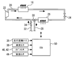
- FIG. 2 is a schematic diagram of an air conditioner system.
- This air conditioning system is an air conditioning system that performs air conditioning in the vehicle 10 and includes a refrigerant circulation circuit 20 that circulates a refrigerant such as carbon dioxide.
- a compressor 22, an expansion valve 24, and an evaporator 26 are provided on the refrigerant circulation circuit 20.
- the compressor 22 is a compressor that compresses the refrigerant.
- the condenser 16 has a function of condensing the refrigerant compressed by the compressor 22.
- the expansion valve 24 is an expansion valve that depressurizes the refrigerant condensed by the condenser 16 by throttle expansion.
- the evaporator 26 is an evaporator that evaporates the refrigerant decompressed by the expansion valve 24.
- the refrigerant circulates through the compressor 22, the condenser 16, the expansion valve 24, and the evaporator 26 in this order, as indicated by arrows.
- the refrigerant is compressed when passing through the compressor 22 and becomes a high temperature and high pressure state, and condensed when passing through the condenser 16 and becomes a low temperature and high pressure state.
- the refrigerant is brought into a low temperature and low pressure state by being decompressed by the expansion valve 24, and is brought into a high temperature and low pressure state by being evaporated by the evaporator 26.
- the refrigerant that has been brought into a high temperature and low pressure state by the evaporator 26 flows through the refrigerant circulation circuit 20, is introduced into the compressor 22, and is compressed by the compressor 22.
- the air conditioner system of FIG. 2 further includes a refrigerant introduction passage 28, a three-way valve 30, a refrigerant return passage 32, and a refrigerant on-off valve 34.
- the refrigerant introduction passage 28 is connected to the refrigerant circulation circuit 20 between the compressor 22 and the evaporator 26 via a three-way valve 30.
- the three-way valve 30 is configured to connect or block the refrigerant circulation circuit 20 and the refrigerant introduction passage 28.
- the refrigerant return passage 32 is connected to the refrigerant circulation circuit 20 on the upstream side of the three-way valve 30.
- the refrigerant opening / closing valve 34 is provided on the refrigerant return passage 32 and is configured to be able to open and close the refrigerant return passage 32 by an opening / closing operation.
- the air purification device of the present embodiment includes an ECU (Electronic Control Unit) 50 as a control device.
- the above-described compressor 22, expansion valve 24, three-way valve 30, refrigerant on-off valve 34, and the like are connected to the output side of the ECU 50.
- a mileage meter 36 capable of grasping the vehicle mileage up to the present time
- a temperature sensor 38 for detecting the temperature of the capacitor 16
- ozone sensors 40, 42 for detecting ozone concentrations in front of and behind the capacitor 16.
- a room temperature sensor 44 for detecting the temperature inside the vehicle is connected.
- the ECU 50 is configured to control various actuators such as the compressor 22 based on signals from the mileage meter 36 and the like.
- FIG. 3 is data showing the results of an ozone purification endurance test for activated carbon.
- the horizontal axis in FIG. 3 represents the endurance distance (kilomile), and the vertical axis represents the relative value based on the ozone purification rate in the initial state (when the endurance distance is 0 kilomile).
- Each data shown in FIG. 3 is prepared by preparing two activated carbons having the same size and specific surface area, and moving ozone-containing gas having a constant concentration from the front to the rear of the two activated carbons at different speeds (wind speed 1 m / s and wind speed). 10 m / s), and obtained by measuring the ozone concentration behind the activated carbon, respectively.
- the ozone purification rate of the activated carbon decreases as the endurance distance increases. Further, as shown in FIG. 3, the degree of decrease in the ozone purification rate of the activated carbon varies depending on the wind speed of the ozone-containing gas to be passed. Specifically, when the ozone-containing gas is passed at a wind speed of 1 m / s, the ozone purification rate is reduced to about half of the initial state at about 30 km, but when the ozone-containing gas is passed at a wind speed of 10 m / s. Even about 30 km, it shows about 70% or more of the initial state, and finally decreases to about half of the initial state around 60 km. That is, the degree of decrease in the ozone purification rate is smaller when passing at a high speed (wind speed of 10 m / s) than when passing at a low speed (wind speed of 1 m / s).
- FIG. 4 is a graph showing the relationship between the wind speed of the gas passing through the capacitor and the probability that the gas contacts the capacitor. This graph was calculated by applying the Gormley-Kennedy diffusion theory formula to the aluminum honeycomb radiator model. As shown in FIG. 4, when the wind speed is around 1 m / s, the probability that the gas contacts the radiator is about 100%, and when the wind speed is around 10 m / s, it decreases to about 10%. That is, the probability that the gas contacts the radiator is high when the wind speed is slow, and gradually decreases as the wind speed increases. In the vehicle 10, the capacitor 16 is installed in front of the radiator 14, so the result of this figure can be applied to the capacitor. Therefore, it can be seen that the probability that the gas contacts the condenser (hereinafter referred to as “gas contact probability”) is high when the wind speed of the gas passing through the condenser is low, and gradually decreases as the wind speed increases.
- gas contact probability the probability that the gas contacts the condenser
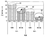
- FIG. 5 is a graph showing the temperature characteristic change before and after the durability test of the ozone purification rate of the activated carbon.
- the graph of FIG. 5 shows the activated carbon (with the same size and specific surface area) in the initial state (endurance distance 0 km) and after the endurance test (endurance distance 50 km) under different temperature conditions (25 ° C. and 75 ° C.)
- the ozone-containing gas having a constant concentration is passed at different speeds (wind speed 1 m / s and wind speed 5 m / s) from the rear to the rear, the ozone concentration behind the activated carbon is measured.
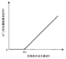
- FIG. 6 is a diagram for explaining the outline of the purification function recovery control in the present embodiment.
- the horizontal axis in FIG. 6 represents the deterioration rate R of the activated carbon, and the vertical axis represents the increased pressure of the compressor 22 (hereinafter referred to as “ozone purification function required pressure P O3 ”).
- the purification function recovery control is executed such that the ozone purification function required pressure PO3 increases as the deterioration rate R of the activated carbon increases. That is, the compressor 22 is controlled so that the capacitor 16 becomes higher as the deterioration rate R of the activated carbon is higher. Thereby, it becomes possible to increase the pressure of the compressor 22 and increase the ozone purification rate of the activated carbon.
- the purification function recovery control is executed only when the deterioration rate R of the activated carbon is higher than a predetermined value Rth . In other words, when the deterioration rate R of the activated carbon is lower than the predetermined value Rth , the purification function recovery control is not executed.
- the purification function recovery control is executed, the ozone purification rate of the activated carbon can be increased, while the activated carbon is more easily deteriorated.
- the purification rate recovery control is not executed when the deterioration rate R of the activated carbon is lower than the predetermined value Rth , the progress of the deterioration of the activated carbon can be suppressed. Further, the execution of the purification function recovery control consumes an amount of fuel corresponding to the pressure increase of the compressor 22, so that the fuel consumption may be deteriorated. Therefore, when the purification rate recovery control is not executed when the deterioration rate R of the activated carbon is lower than the predetermined value Rth , it is possible to suppress deterioration in fuel consumption. Therefore, it is possible to maximize the use of the purification function while extending the life of the activated carbon.
- the deterioration ratio R of the activated carbon is referred to as a correction value calculated from the ozone concentration ratio in the upstream and downstream of the capacitor 16 (hereinafter referred to as “concentration correction value”) to a reference value calculated according to the travel distance of the vehicle 10. And a correction value based on an average value of the temperature history of the capacitor 16 (hereinafter referred to as “temperature history correction value”). It is assumed that the ECU 50 stores therein map data in advance regarding the relationship between the reference value and the vehicle travel distance. Similarly, the ECU 50 stores therein map data in advance for the relationship between the concentration correction value and the ozone concentration ratio and the relationship between the temperature history correction value and the average value of the temperature history. To do.
- FIG. 7 is a flowchart showing the purification function recovery control executed by the ECU 50 in the present embodiment. Note that the routine shown in FIG. 7 is repeatedly executed periodically.
- the ECU 50 calculates a required cooling pressure PA / C for the air conditioner system (step 100).
- the required cooling pressure PA / C is the pressure of the compressor 22 corresponding to the in-vehicle temperature (hereinafter referred to as “required temperature T rq ”) set by the driver of the vehicle 10, and is converted into map data in advance and stored in the ECU 50. It is assumed that it is stored in In this step, the ECU 50 reads the required cooling pressure PA / C corresponding to the required temperature T rq with reference to this map data.
- the required cooling pressure PA / C is set to zero.
- the purification flag is a flag that is set to 1 in the second and third embodiments to be described later under the condition that the execution of the purification function recovery control is prohibited, and is 0 under the condition that the execution of the purification function recovery control is permitted.
- Set to This purification prohibition flag is reset to 0 when the internal combustion engine 12 is stopped.
- step 110 If it is determined in step 110 that the purification prohibition flag is 1, the ECU 50 sets the required compressor pressure P COM to the required cooling pressure PA / C calculated in step 100 (step 120). On the other hand, when it is determined in step 110 that the purification prohibition flag is 0, the ECU 50 calculates the ozone purification function required pressure PO3 (step 130). Specifically, the ECU 50 reads the reference value with reference to map data that defines the relationship between the detected value of the mileage meter 36 and the reference value. At the same time, the ECU 50 reads the density correction value and the temperature history correction value with reference to each map data. Then, the ECU 50 calculates the ozone purification function required pressure P03 based on these values.
- ECU 50 calculates the compressor required pressure P COM (step 140). Specifically, the ECU 50 adds the required cooling pressure PA / C calculated in step 100 and the ozone purification function required pressure P03 calculated in step 120. Then, the compressor 22 is operated at the compressor required pressure P COM calculated by the process of step 140 or step 120.
- the compressor required pressure P COM is obtained by adding the ozone purification function required pressure P O3 to the cooling required pressure PA / C.
- the operating pressure of the compressor 22 can be controlled. Therefore, the ozone purification rate of the activated carbon can be increased in accordance with the deterioration rate R of the activated carbon under the condition where the execution of the purification function recovery control is permitted. Therefore, it is possible to maximize the use of the purification function while extending the life of the activated carbon.
- activated carbon is used as the ozone purifier, but as the ozone purifier, simple substance such as manganese, iron, cobalt, nickel, copper, ruthenium, rhodium, palladium, silver, platinum or gold is used together with the activated carbon.
- Metals, metal complexes or organometallic complexes having these single metals as the central metal, or zeolite may be used. These simple metals, metal complexes, organometallic complexes and zeolites have an ozone purification function like activated carbon, and can be used together with activated carbon to suppress deterioration of the ozone purification function of activated carbon.
- activated carbon is provided in the core portion of the capacitor 16, but activated carbon may be provided in the core portion of the radiator 14 instead of the core portion of the capacitor 16 or together with the core portion of the capacitor 16.
- the average operating temperature of the radiator is higher than that of the condenser (Radiator: 75 ° C to 95 ° C, Capacitor: 60 ° C to 80 ° C), so the temperature of the air passing through the radiator is higher than the temperature of the air passing through the condenser. Get higher. Therefore, since the probability that the atmosphere contacts the radiator 14 is higher than the probability that the atmosphere contacts the capacitor 16, the activated carbon provided in the core portion of the radiator 14 is more than the activated carbon provided in the core portion of the capacitor 16. The degree of decrease in the ozone purification rate increases (see FIGS. 3 and 4).
- activated carbon may be provided in the core portion of the radiator 14. This modification can also be applied to Embodiments 2 and 3 described later.
- the ECU 50 increases the pressure of the compressor 22 to increase the temperature of the capacitor 16 during the purification function recovery control.
- the means for heating the capacitor 16 is not limited to this.
- the condenser 16 may be heated using the exhaust heat of the internal combustion engine 12, or the condenser 16 may be heated using a heating device such as a separately installed heater.
- the deterioration rate R of the activated carbon is calculated by integrating the concentration correction value and the temperature history correction value to the reference value calculated according to the travel distance of the vehicle 10.
- the ratio R may be calculated using only the reference value, may be calculated by adding only the density correction value to the reference value, or may be calculated using only the density correction value. That is, the deterioration ratio R of the activated carbon may be calculated using at least one parameter among the reference value, the concentration correction value, and the temperature history correction value. In addition to these parameters, the deterioration rate R of the activated carbon may be calculated using other parameters. This modification can also be applied to Embodiments 2 and 3 described later.
- the capacitor 16 corresponds to the “vehicle component” in the first invention.
- the “purification function recovery control means” in the first aspect of the present invention is realized by the ECU 50 executing the series of processes of FIG.
- Embodiment 2 of the present invention will be described with reference to FIG.
- the present embodiment is characterized in that the purification function recovery control shown in FIG. 8 is executed in the configuration shown in FIGS. Therefore, in the following description, differences from the first embodiment will be mainly described, and descriptions of similar matters will be simplified or omitted.
- the purification function recovery control when the activated carbon deterioration rate R is higher than the predetermined value Rth , the pressure of the compressor 22 is increased to increase the ozone purification rate of the activated carbon.
- the execution of the purification function recovery control consumes the amount of fuel corresponding to the pressure increase of the compressor 22, so that the fuel consumption may be deteriorated. Therefore, in the present embodiment, the execution of the purification function recovery control is prohibited under environmental conditions where the ozone concentration in the atmosphere is low. It can be said that the ozone purification efficiency by the execution of the purification function recovery control is relatively low under an environmental condition where the ozone concentration in the atmosphere is low. Therefore, according to the present embodiment, it is possible to suppress deterioration in fuel consumption due to the execution of the purification function recovery control, and it is possible to extend the life of the activated carbon through the efficient execution of the control.
- FIG. 8 is a flowchart showing the purification function recovery control executed by the ECU 50 in the present embodiment. Note that the routine shown in FIG. 8 is executed periodically and repeatedly instead of the routine shown in FIG.
- the ECU 50 calculates the required cooling pressure PA / C for the air conditioner system (step 200) and determines whether or not the purification prohibition flag is 0 (step 210). If it is determined in step 210 that the purification prohibition flag is 1, the ECU 50 sets the required compressor pressure P COM to the required cooling pressure PA / C calculated in step 200 (step 270). On the other hand, when it is determined in step 210 that the purification prohibition flag is 0, the ECU 50 calculates the ozone purification function required pressure PO3 (step 220). Since a series of processing in steps 200 to 220 and 270 is the same as the processing in steps 100 to 130 in FIG. 7, further explanation is omitted.
- the ECU 50 acquires the ozone concentration C O3 (step 230), and determines whether or not the acquired ozone concentration C O3 is equal to or lower than a predetermined concentration C th (step 240). Specifically, the ECU 50 acquires a detection value of the ozone sensor 40 and compares this detection value with a predetermined concentration Cth stored in the ECU 50 in advance.
- the ECU 50 determines the required cooling pressure PA / C calculated in step 200 and the ozone purification function request calculated in step 220.
- the compressor required pressure PCOM is calculated by adding the pressure PO3 (step 250).
- the ECU 50 sets the purification prohibition flag to 1 (step 260) and sets the compressor required pressure P COM to step 200.
- the required cooling pressure PA / C calculated in step 270 is set (step 270).
- the ozone concentration is acquired from the detection value of the ozone sensor 40, but instead of the detection value of the ozone sensor 40, the travel area information relating to the ozone concentration such as navigation information, outside air temperature, season, and time is used. Based on this, the ozone concentration may be acquired indirectly. Moreover, you may acquire the value which combined these travel area information with the detected value of the ozone sensor 40 as ozone concentration.
- the ozone sensor 40 corresponds to the “ozone concentration acquisition means” in the third invention.
- the “ozone concentration comparison means” in the third aspect of the present invention is realized by the ECU 50 executing the process of step 240 in FIG.
- Embodiment 3 FIG. Next, Embodiment 3 of the present invention will be described with reference to FIG.
- the present embodiment is characterized in that the function recovery stop control shown in FIG. 9 is executed in the configuration shown in FIGS. Therefore, in the following description, differences from the first embodiment will be mainly described, and descriptions of similar matters will be simplified or omitted.
- the purification function recovery control is such that the ozone purification function required pressure P03 is added to the cooling required pressure PA / C. Therefore, the actual in-vehicle temperature T in may not reach the required temperature T rq . Therefore, in the present embodiment, even when a predetermined time has elapsed after the execution of the purification function recovery control is started, there is still a temperature difference between the in- vehicle temperature T in and the required temperature T rq . Therefore, the execution of the purification function recovery control is stopped (function recovery stop control).
- FIG. 9 is a flowchart showing the function recovery stop control executed by the ECU 50 in the present embodiment. It is assumed that the routine shown in FIG. 9 is executed in parallel with these routines at every repetition timing of the routines shown in FIGS.
- the ECU 50 determines whether or not a predetermined time has elapsed since the start of the purification function recovery control (step 300). Specifically, the ECU 50 counts the elapsed time after the start of the routine of FIG. 7 or FIG. 8, and determines whether or not this elapsed time exceeds a predetermined time. Note that a value stored in the ECU 50 after being set in advance is used as the predetermined time.
- step 300 If it is determined in step 300 that the predetermined time has not elapsed since the execution of the purification function recovery control is started, the ECU 50 returns to step 300 again and executes the same processing.
- step 300 if the predetermined time from the start of the purification function recovery control is determined to have elapsed, ECU 50 acquires the vehicle temperature T in (step 310), inside temperature T in the required temperature temperature difference T in -T rq with T rq determines whether is outside a predetermined temperature range (step 320). Specifically, the ECU 50 acquires the detected value of the room temperature sensor 44, and also calculates the absolute value of the temperature difference between the detected value and the required temperature T rq and the predetermined temperature T th stored in advance in the ECU 50. Compare.
- step 320 When it is determined in step 320 that the temperature difference T in ⁇ T rq between the in -vehicle temperature T in and the required temperature T rq is outside the predetermined temperature range, the ECU 50 sets the purification prohibition flag to 1 (step 330). . On the other hand, when it is determined that the temperature difference T in ⁇ T rq between the in -vehicle temperature T in and the required temperature T rq is within the predetermined temperature range, the ECU 50 ends this routine.
- the ozone purification function An increase in the pressure of the compressor 22 for the purpose of recovering the pressure is prohibited. Accordingly, the in- vehicle temperature T in can be quickly reached the required temperature T rq by giving priority to the in-vehicle cooling request.
- the “temperature difference determination means” is realized by executing the process of step 320 in FIG.
Landscapes
- Health & Medical Sciences (AREA)
- Chemical & Material Sciences (AREA)
- Engineering & Computer Science (AREA)
- Chemical Kinetics & Catalysis (AREA)
- Environmental & Geological Engineering (AREA)
- Analytical Chemistry (AREA)
- General Chemical & Material Sciences (AREA)
- Oil, Petroleum & Natural Gas (AREA)
- Biomedical Technology (AREA)
- Epidemiology (AREA)
- Life Sciences & Earth Sciences (AREA)
- Animal Behavior & Ethology (AREA)
- General Health & Medical Sciences (AREA)
- Public Health (AREA)
- Veterinary Medicine (AREA)
- Air-Conditioning For Vehicles (AREA)
Abstract
Description
車両の走行時に大気の流路が形成される箇所に配置された車両構成部品と、
前記車両構成部品に設けられ、活性炭を含むオゾン浄化体と、
前記オゾン浄化体の劣化度合いに応じて前記オゾン浄化体を高温化させる浄化機能回復制御を実行する浄化機能回復制御手段と、
を備えることを特徴とする。
前記浄化機能回復制御手段は、前記オゾン浄化体の劣化度合いが基準値を超えるまでは、前記浄化機能回復制御の実行を禁止することを特徴とする。
大気中のオゾン濃度を取得するオゾン濃度取得手段と、
前記オゾン濃度と設定濃度とを比較するオゾン濃度比較手段と、を備え、
前記浄化機能回復制御手段は、前記オゾン濃度が設定濃度よりも低い場合は、前記浄化機能回復制御の実行を禁止することを特徴とする。
前記車両構成部品は、エアコンのコンデンサであり、
前記エアコンに対する要求温度と車内温度との温度差が、設定温度範囲外にあるか否かを判定する温度差判定手段を更に備え、
前記浄化機能回復制御手段は、前記浄化機能回復制御の実行を開始してから設定時間の経過後における前記温度差が前記設定温度範囲外にある場合は、前記浄化機能回復制御の実行を停止することを特徴とする。
[車両用大気浄化装置の構成]
先ず、図1乃至図7を参照しながら、本発明の実施の形態1について説明する。図1は、本実施の形態の大気浄化装置を搭載した車両の構成を示す概略図である。車両10は、動力装置としての内燃機関12を備えている。内燃機関12から排出される排気ガスには、HCやNOxが含まれている。オゾンはHCやNOxを反応物として光化学反応により生成される。そのため、内燃機関12を備える車両10に大気浄化装置を搭載し、車両10の走行中に大気中のオゾンを浄化することで、車両10が環境に与える影響を低減することができる。
図3は、活性炭のオゾン浄化耐久試験の結果を示すデータである。図3の横軸は耐久距離(キロマイル)を、縦軸は初期状態(耐久距離0キロマイル時)におけるオゾン浄化率を基準とした相対値を、それぞれ示す。図3中に示す各データは、サイズおよび比表面積が同等の2つの活性炭を準備し、この2つの活性炭の前方から後方に向けて一定濃度のオゾン含有ガスを異なる速度(風速1m/sおよび風速10m/s)で通過させた際に、活性炭後方のオゾン濃度をそれぞれ測定することにより得たものである。
次に、図7を参照して、上述した浄化機能回復制御を実現するための具体的な処理について説明する。図7は、本実施の形態において、ECU50により実行される浄化機能回復制御を示すフローチャートである。なお、図7に示すルーチンは、定期的に繰り返して実行されるものとする。
次に、図8を参照しながら、本発明の実施の形態2について説明する。本実施の形態では、図1および図2に示した構成において、図8に示す浄化機能回復制御を実行することをその特徴とする。そのため、以下においては、上記実施の形態1との相違点を中心に説明し、同様の事項については、その説明を簡略化または省略する。
上記実施の形態1においては、浄化機能回復制御として、活性炭の劣化割合Rが所定値Rthよりも高い場合にコンプレッサ22の圧力を増加させて活性炭のオゾン浄化率を上昇させた。しかしながら、上述したように、浄化機能回復制御の実行は、コンプレッサ22の圧力増加分に応じた燃料量を消費するので、燃費が悪化する可能性がある。そこで、本実施の形態においては、大気中のオゾン濃度が低い環境条件下では、浄化機能回復制御の実行を禁止することとした。大気中のオゾン濃度が低い環境条件下では、浄化機能回復制御の実行によるオゾン浄化効率が相対的に低いと言える。従って、本実施の形態によれば、浄化機能回復制御の実行による燃費悪化を抑制できると共に、効率的な制御実行による活性炭の長寿命化を図ることができる。
次に、図8を参照して、本実施の形態における浄化機能回復制御を実現するための具体的な処理について説明する。図8は、本実施の形態において、ECU50により実行される浄化機能回復制御を示すフローチャートである。なお、図8に示すルーチンは、図7に示したルーチンに代えて、定期的に繰り返して実行されるものとする。
次に、図9を参照しながら、本発明の実施の形態3について説明する。本実施の形態では、図1および図2に示した構成において、図9に示す機能回復停止制御を実行することをその特徴とする。そのため、以下においては、上記実施の形態1との相違点を中心に説明し、同様の事項については、その説明を簡略化または省略する。
上述したように、浄化機能回復制御は、冷却要求圧PA/Cにオゾン浄化機能要求圧PO3が加算するものである。そのため、実際の車内温度Tinが要求温度Trqに到達しない可能性がある。そこで、本実施の形態においては、浄化機能回復制御の実行を開始してから所定時間が経過した後においても、車内温度Tinと要求温度Trqとの間に依然として温度差が生じている場合には、浄化機能回復制御の実行を停止することとした(機能回復停止制御)。
次に、図9を参照して、上述した機能回復停止制御を実現するための具体的な処理について説明する。図9は、本実施の形態において、ECU50により実行される機能回復停止制御を示すフローチャートである。なお、図9に示すルーチンは、図7や図8に示したルーチンの繰り返しタイミング毎に、これらのルーチンと並行して実行されるものとする。
12 内燃機関
14 ラジエータ
16 コンデンサ
18 バンパーグリル
20 冷媒循環回路
22 コンプレッサ
24 膨張弁
26 エバポレータ
28 冷媒導入通路
30 三方弁
32 冷媒戻し通路
34 冷媒開閉弁
36 走行距離メータ
38 温度センサ
40,42 オゾンセンサ
44 室温センサ
50 ECU
Claims (4)
- 車両の走行時に大気の流路が形成される箇所に配置された車両構成部品と、
前記車両構成部品に設けられ、活性炭を含むオゾン浄化体と、
前記オゾン浄化体の劣化度合いに応じて前記オゾン浄化体を高温化させる浄化機能回復制御を実行する浄化機能回復制御手段と、
を備えることを特徴とする車両用大気浄化装置。 - 前記浄化機能回復制御手段は、前記オゾン浄化体の劣化度合いが基準値を超えるまでは、前記浄化機能回復制御の実行を禁止することを特徴とする請求項1に記載の車両用大気浄化装置。
- 大気中のオゾン濃度を取得するオゾン濃度取得手段と、
前記オゾン濃度と設定濃度とを比較するオゾン濃度比較手段と、を備え、
前記浄化機能回復制御手段は、前記オゾン濃度が設定濃度よりも低い場合は、前記浄化機能回復制御の実行を禁止することを特徴とする請求項1または2に記載の車両用大気浄化装置。 - 前記車両構成部品は、エアコンのコンデンサであり、
前記エアコンに対する要求温度と車内温度との温度差が、設定温度範囲外にあるか否かを判定する温度差判定手段を更に備え、
前記浄化機能回復制御手段は、前記浄化機能回復制御の実行を開始してから設定時間の経過後における前記温度差が前記設定温度範囲外にある場合は、前記浄化機能回復制御の実行を停止することを特徴とする請求項1乃至3何れか1項に記載の車両用大気浄化装置。
Priority Applications (4)
| Application Number | Priority Date | Filing Date | Title |
|---|---|---|---|
| JP2013506977A JP5725160B2 (ja) | 2011-03-31 | 2011-03-31 | 車両用大気浄化装置 |
| DE112011105120.4T DE112011105120T5 (de) | 2011-03-31 | 2011-03-31 | Fahrzeugluftreiniger |
| US14/003,300 US10342885B2 (en) | 2011-03-31 | 2011-03-31 | Vehicular air cleaner |
| PCT/JP2011/058190 WO2012131967A1 (ja) | 2011-03-31 | 2011-03-31 | 車両用大気浄化装置 |
Applications Claiming Priority (1)
| Application Number | Priority Date | Filing Date | Title |
|---|---|---|---|
| PCT/JP2011/058190 WO2012131967A1 (ja) | 2011-03-31 | 2011-03-31 | 車両用大気浄化装置 |
Publications (1)
| Publication Number | Publication Date |
|---|---|
| WO2012131967A1 true WO2012131967A1 (ja) | 2012-10-04 |
Family
ID=46929789
Family Applications (1)
| Application Number | Title | Priority Date | Filing Date |
|---|---|---|---|
| PCT/JP2011/058190 Ceased WO2012131967A1 (ja) | 2011-03-31 | 2011-03-31 | 車両用大気浄化装置 |
Country Status (4)
| Country | Link |
|---|---|
| US (1) | US10342885B2 (ja) |
| JP (1) | JP5725160B2 (ja) |
| DE (1) | DE112011105120T5 (ja) |
| WO (1) | WO2012131967A1 (ja) |
Cited By (1)
| Publication number | Priority date | Publication date | Assignee | Title |
|---|---|---|---|---|
| JPWO2013014792A1 (ja) * | 2011-07-28 | 2015-02-23 | トヨタ自動車株式会社 | 車両用大気浄化装置 |
Citations (4)
| Publication number | Priority date | Publication date | Assignee | Title |
|---|---|---|---|---|
| JPH11300149A (ja) * | 1998-04-27 | 1999-11-02 | Denso Corp | 車両用空調装置の空気清浄装置 |
| JP2005169158A (ja) * | 2003-12-05 | 2005-06-30 | Honda Motor Co Ltd | 車両用オゾン浄化装置 |
| JP2007069749A (ja) * | 2005-09-07 | 2007-03-22 | Honda Motor Co Ltd | 車載診断装置及び触媒層の浄化性能の劣化判定方法 |
| JP2010029816A (ja) * | 2008-07-30 | 2010-02-12 | Toyota Motor Corp | 大気浄化装置 |
Family Cites Families (34)
| Publication number | Priority date | Publication date | Assignee | Title |
|---|---|---|---|---|
| DE361741C (de) | 1917-09-11 | 1923-05-24 | Wilhelm Schwarzenauer | Verfahren zur Beseitigung von Abwaessern, Ablaugen o. dgl. |
| JPS5945741B2 (ja) | 1982-10-29 | 1984-11-08 | 東京ニツケル株式会社 | 酸化ニツケルの流動還元方法 |
| DE4007965C2 (de) | 1990-03-13 | 1994-03-10 | Klaus Hager | Kupferoxide oder eine Mischung aus Kupferoxiden und Manganoxiden enthaltender Katalysator und seine Verwendung |
| AU4701196A (en) | 1995-01-20 | 1996-08-07 | Engelhard Corporation | Pollutant treating device located in vehicle compartment for cleaning ambient air |
| KR100445771B1 (ko) | 1995-01-20 | 2004-11-10 | 엥겔하드 코포레이션 | 정치기판과의접촉에의한주위공기의청정방법및장치 |
| US6818254B1 (en) * | 1995-01-20 | 2004-11-16 | Engelhard Corporation | Stable slurries of catalytically active materials |
| US6200542B1 (en) * | 1995-01-20 | 2001-03-13 | Engelhard Corporation | Method and apparatus for treating the atmosphere |
| ATE300994T1 (de) | 1995-09-29 | 2005-08-15 | Engelhard Corp | Umgebungsluftreinigung mittels der bewegung eines fahrzeugs, welches eine oberfläche zur schadstoffbehandlung enthält |
| US5914294A (en) | 1996-04-23 | 1999-06-22 | Applied Ceramics, Inc. | Adsorptive monolith including activated carbon and method for making said monlith |
| DE19624216B4 (de) | 1996-06-18 | 2005-04-28 | Behr Gmbh & Co Kg | Vorrichtung und Verfahren zur Behandlung eines einem Fahrzeuginnenraum zugeführten Luftstroms |
| US6280691B1 (en) | 1997-03-31 | 2001-08-28 | Alliedsignal Inc. | Indoor air purification system |
| DE19806880A1 (de) | 1998-02-19 | 1999-08-26 | Behr Gmbh & Co | Verfahren zur Steuerung einer Vorrichtung zur Behandlung eines einem Fahrzeuginnenraum zuführbaren Luftstromes |
| DE19838996A1 (de) | 1998-08-27 | 2000-03-02 | Valeo Klimasysteme Gmbh | Klimaanlage mit Aktivkohlefilter |
| US6410746B1 (en) * | 1999-04-27 | 2002-06-25 | Research Foundation Of State University Of New York, The | Metal cataltsts and methods for making and using same |
| DE19955253B4 (de) | 1999-11-17 | 2006-07-13 | Daimlerchrysler Ag | Filtervorrichtung |
| JP2001347829A (ja) | 2000-06-07 | 2001-12-18 | Honda Motor Co Ltd | 車両用オゾン浄化装置 |
| US6835356B2 (en) | 2000-03-03 | 2004-12-28 | Honda Giken Kogyo Kabushiki Kaisha | Ozone purifying apparatus for vehicle |
| JP2001323811A (ja) | 2000-03-10 | 2001-11-22 | Honda Motor Co Ltd | 排気ガス浄化触媒の状態検出装置 |
| DE10032095B4 (de) * | 2000-07-01 | 2005-06-23 | Dr.Ing.H.C. F. Porsche Ag | Kurbeltrieb für eine Brennkraftmaschine |
| US20020172633A1 (en) * | 2001-03-06 | 2002-11-21 | Koermer Gerald S. | Vehicular atmosphere cleansing system |
| EG23455A (en) * | 2001-08-01 | 2005-09-28 | Sharp Kk | Ion generator and electric apparatus and their uses in an air condition. |
| JP3926694B2 (ja) | 2001-09-07 | 2007-06-06 | 本田技研工業株式会社 | 排気ガス浄化装置の状態判定装置 |
| US20040159335A1 (en) * | 2002-05-17 | 2004-08-19 | P.C.T. Systems, Inc. | Method and apparatus for removing organic layers |
| FR2848500B1 (fr) | 2002-12-16 | 2006-09-29 | Renault Sa | Dispositif d'alimentation d'air et procede de regeneration d'un filtre a gaz pour habitacle de vehicule |
| JP2004321920A (ja) | 2003-04-24 | 2004-11-18 | Matsushita Electric Ind Co Ltd | 空気清浄化装置とその劣化診断方法 |
| JP4345752B2 (ja) | 2006-02-02 | 2009-10-14 | トヨタ自動車株式会社 | 排熱回収装置 |
| CN101778804A (zh) | 2007-06-22 | 2010-07-14 | 开利公司 | 使用臭氧与吸附剂和/或颗粒过滤器净化流体 |
| JP2010000848A (ja) | 2008-06-19 | 2010-01-07 | Toyota Motor Corp | 大気浄化触媒装置の異常検出装置 |
| JP2010071080A (ja) | 2008-09-16 | 2010-04-02 | Denso Corp | 車両用冷却システムの異常診断装置 |
| JP5197548B2 (ja) * | 2009-11-05 | 2013-05-15 | 本田技研工業株式会社 | 内燃機関の燃料噴射制御装置 |
| JPWO2012127643A1 (ja) | 2011-03-23 | 2014-07-24 | トヨタ自動車株式会社 | 車両用大気浄化装置 |
| BR112013023823B1 (pt) | 2011-03-23 | 2020-12-29 | Toyota Jidosha Kabushiki Kaisha | limpador de ar para veículos |
| JP5790764B2 (ja) | 2011-07-28 | 2015-10-07 | トヨタ自動車株式会社 | 車両用大気浄化装置 |
| RU2014120885A (ru) | 2011-11-24 | 2015-12-27 | Тойота Дзидося Кабусики Кайся | Аппарат для очистки атмосферного воздуха в транспортном средстве |
-
2011
- 2011-03-31 US US14/003,300 patent/US10342885B2/en not_active Expired - Fee Related
- 2011-03-31 DE DE112011105120.4T patent/DE112011105120T5/de not_active Ceased
- 2011-03-31 JP JP2013506977A patent/JP5725160B2/ja not_active Expired - Fee Related
- 2011-03-31 WO PCT/JP2011/058190 patent/WO2012131967A1/ja not_active Ceased
Patent Citations (4)
| Publication number | Priority date | Publication date | Assignee | Title |
|---|---|---|---|---|
| JPH11300149A (ja) * | 1998-04-27 | 1999-11-02 | Denso Corp | 車両用空調装置の空気清浄装置 |
| JP2005169158A (ja) * | 2003-12-05 | 2005-06-30 | Honda Motor Co Ltd | 車両用オゾン浄化装置 |
| JP2007069749A (ja) * | 2005-09-07 | 2007-03-22 | Honda Motor Co Ltd | 車載診断装置及び触媒層の浄化性能の劣化判定方法 |
| JP2010029816A (ja) * | 2008-07-30 | 2010-02-12 | Toyota Motor Corp | 大気浄化装置 |
Cited By (1)
| Publication number | Priority date | Publication date | Assignee | Title |
|---|---|---|---|---|
| JPWO2013014792A1 (ja) * | 2011-07-28 | 2015-02-23 | トヨタ自動車株式会社 | 車両用大気浄化装置 |
Also Published As
| Publication number | Publication date |
|---|---|
| US20140037508A1 (en) | 2014-02-06 |
| JP5725160B2 (ja) | 2015-05-27 |
| DE112011105120T5 (de) | 2014-01-16 |
| JPWO2012131967A1 (ja) | 2014-07-24 |
| US10342885B2 (en) | 2019-07-09 |
Similar Documents
| Publication | Publication Date | Title |
|---|---|---|
| EP2738026B1 (en) | Vehicle atmosphere purifying apparatus | |
| US20150007731A1 (en) | Vehicular atmosphere purifying apparatus | |
| CN103561978B (zh) | 车辆用空调控制装置、车辆用空调控制方法、车辆用空调控制程序、及记录介质 | |
| JP2010029816A (ja) | 大気浄化装置 | |
| JP5672373B2 (ja) | 車両用大気浄化装置 | |
| JP5725160B2 (ja) | 車両用大気浄化装置 | |
| JP6863080B2 (ja) | 電子制御装置 | |
| JP5796535B2 (ja) | 車両用空調装置 | |
| JP2012036857A (ja) | 触媒劣化診断装置 | |
| JP2010000848A (ja) | 大気浄化触媒装置の異常検出装置 | |
| JP6089930B2 (ja) | 車両用大気浄化装置 | |
| JP2018199367A (ja) | 電子制御装置 | |
| JP2013249021A (ja) | 電気自動車等の空調装置 | |
| JP2014031784A (ja) | 冷却システムの異常診断装置 | |
| JP2014033981A (ja) | 車両用大気浄化装置 | |
| US20180274464A1 (en) | Motor vehicle including a lean nox trap regeneration system and method for regeneration | |
| JP5884809B2 (ja) | 車両用大気浄化装置 | |
| JP2014030796A (ja) | 車両用大気浄化装置 | |
| CN104246416B (zh) | 车辆用大气净化装置 | |
| JP2014213283A (ja) | 車両用大気浄化装置 | |
| JPWO2013076833A1 (ja) | 車両用大気浄化装置 | |
| JP6677154B2 (ja) | 排気浄化装置 | |
| JP2014019259A (ja) | オゾン浄化機能異常判定システム | |
| JP2012036838A (ja) | 内燃機関の異常診断装置 | |
| CN108569103A (zh) | 一种车载空气净化系统 |
Legal Events
| Date | Code | Title | Description |
|---|---|---|---|
| 121 | Ep: the epo has been informed by wipo that ep was designated in this application |
Ref document number: 11862814 Country of ref document: EP Kind code of ref document: A1 |
|
| ENP | Entry into the national phase |
Ref document number: 2013506977 Country of ref document: JP Kind code of ref document: A |
|
| WWE | Wipo information: entry into national phase |
Ref document number: 14003300 Country of ref document: US |
|
| WWE | Wipo information: entry into national phase |
Ref document number: 1120111051204 Country of ref document: DE Ref document number: 112011105120 Country of ref document: DE |
|
| 122 | Ep: pct application non-entry in european phase |
Ref document number: 11862814 Country of ref document: EP Kind code of ref document: A1 |