WO2012131929A1 - タイヤ加硫装置 - Google Patents
タイヤ加硫装置 Download PDFInfo
- Publication number
- WO2012131929A1 WO2012131929A1 PCT/JP2011/057953 JP2011057953W WO2012131929A1 WO 2012131929 A1 WO2012131929 A1 WO 2012131929A1 JP 2011057953 W JP2011057953 W JP 2011057953W WO 2012131929 A1 WO2012131929 A1 WO 2012131929A1
- Authority
- WO
- WIPO (PCT)
- Prior art keywords
- vulcanizing apparatus
- tire vulcanizing
- tire
- heating element
- heating
- Prior art date
- Legal status (The legal status is an assumption and is not a legal conclusion. Google has not performed a legal analysis and makes no representation as to the accuracy of the status listed.)
- Ceased
Links
Images






Classifications
-
- B—PERFORMING OPERATIONS; TRANSPORTING
- B29—WORKING OF PLASTICS; WORKING OF SUBSTANCES IN A PLASTIC STATE IN GENERAL
- B29D—PRODUCING PARTICULAR ARTICLES FROM PLASTICS OR FROM SUBSTANCES IN A PLASTIC STATE
- B29D30/00—Producing pneumatic or solid tyres or parts thereof
- B29D30/06—Pneumatic tyres or parts thereof (e.g. produced by casting, moulding, compression moulding, injection moulding, centrifugal casting)
- B29D30/0601—Vulcanising tyres; Vulcanising presses for tyres
- B29D30/0662—Accessories, details or auxiliary operations
-
- B—PERFORMING OPERATIONS; TRANSPORTING
- B29—WORKING OF PLASTICS; WORKING OF SUBSTANCES IN A PLASTIC STATE IN GENERAL
- B29D—PRODUCING PARTICULAR ARTICLES FROM PLASTICS OR FROM SUBSTANCES IN A PLASTIC STATE
- B29D30/00—Producing pneumatic or solid tyres or parts thereof
- B29D30/06—Pneumatic tyres or parts thereof (e.g. produced by casting, moulding, compression moulding, injection moulding, centrifugal casting)
- B29D30/0601—Vulcanising tyres; Vulcanising presses for tyres
- B29D30/0662—Accessories, details or auxiliary operations
- B29D2030/0666—Heating by using fluids
- B29D2030/0674—Heating by using non-fluid means, e.g. electrical heating
Definitions
- the present invention relates to a tire vulcanizing apparatus for vulcanizing a green tire.
- FIG. 10 As a means for heating the raw tire from the outside, for example, there is one as shown in FIG. 10 (see Patent Document 1 and Patent Document 2).
- the upper and lower platens 100a and 100b, the jacket ring 101 as the outer ring, and the like are formed as flow paths in the upper and lower platens 100a and 100b as the outer mold of the vulcanizing mold that accommodates the raw tire T.
- Steam (heating medium) is supplied and circulated from the factory steam boiler 104 through the piping unit 102 and the factory main pipe 103 to the flow path (see piping in the figure), and heat is transferred from the outer mold to the raw tire T. is there.
- the steam described above is supplied and circulated through the lower center mechanism (not shown) into the internal space (in the bladder B) of the raw tire T, and heating or pressurized medium such as nitrogen (N2) gas or hot water is supplied. It is designed to be sealed.
- heating or pressurized medium such as nitrogen (N2) gas or hot water
- an electromagnetic coil is arranged around the outer mold, the surface of the outer mold is induction-heated (see Patent Document 3 and Patent Document 4), and a rod heater is embedded in the outer mold, There is one that indirectly heats the outer mold (see Patent Document 5 and Patent Document 6).
- the steam heating method as shown in FIG. 10 has a problem that the running cost becomes high because a large energy loss occurs due to heat radiation from the steam supply pipe.
- it requires piping work between the factory main pipe and the vulcanizer, which cannot be changed easily, which makes the factory layout very difficult, or condensate drain in the steam flow path between the upper and lower plates.
- problems such as difficulty in controlling the zone temperature.
- the induction heating method it takes a lot of time to control the heating (adjusting the magnetic force and magnetic field) according to the structure of the vulcanizer and the tire mold, and also for the installation of electromagnetic coils and electrical insulation materials. As a result, the size of the apparatus increases, leading to an increase in cost.
- an object of the present invention is to provide a tire vulcanizing apparatus provided with heating means that can reduce energy loss and running cost, improve temperature control accuracy, and is inexpensive and has good workability.
- a tire vulcanizing apparatus for achieving such an object,
- a tire vulcanizing apparatus for heating and vulcanizing a raw tire housed in an outer mold from outside and inside the raw tire As a means for heating the green tire from at least the outside, a flexible planar heating element used for ordinary household appliances is attached to the outer mold, and the outer mold is heated directly or via a heat medium. It is characterized by doing.
- the flexible planar heating element is a mica heater.
- the flexible planar heating element is divided into a plurality of parts according to the zone temperature control of the outer mold.
- the flexible planar heating element is attached in combination with a heat insulating material.
- the flexible planar heating element is partly attached in a steam heating type tire vulcanizer.
- the tire vulcanizing apparatus according to the present invention does not use steam from a factory steam boiler, so that energy loss and running cost can be reduced.
- the simple means of attaching a flexible planar heating element used for household appliances has the advantage that the heating running cost can be reduced, the accuracy of temperature control can be improved, and the cost can be reduced.
- FIG. 1 is a heating system diagram of a tire vulcanizing apparatus showing an embodiment of the present invention
- FIG. 2 is a mounting structure diagram of a mica heater
- FIG. 3A is a mounting structure diagram of a mica heater, a heat insulating material, and a platen
- FIG. 4A is a mounting structure diagram of the mica heater and the platen
- FIG. 4B is another mounting structure diagram of the mica heater and the platen
- FIG. 5 is a mounting structure diagram of the mica heater, the platen, and the heating medium
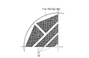
- FIG. FIG. 6B is a plan view showing another divided pattern of the mica heater in the platen
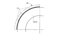
- FIG. 7A is a flat (lateral) sectional view showing the mounting structure of the mica heater and the jacket ring
- FIG. 7B is a mica heater.
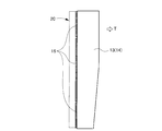
- 8A is a side (longitudinal) cross-sectional view showing the mounting structure of the jacket ring
- FIG. 8B is a side (vertical) cross-sectional view showing the mounting structure of the mica heater, the heat insulating material, and the jacket ring
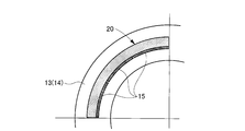
- FIG. 9A is a flat (horizontal) showing the mounting structure of the mica heater, the heat medium, and the jacket ring.
- Cross-sectional view FIG. 9B is a side (vertical) cross-sectional view showing the mounting structure of the mica heater, the heat medium, and the jacket ring.
- a container 10 of a tire vulcanizer includes a plate made of upper and lower platens 11a and 11b and upper and lower container plates 12a and 12b, a jacket ring 13 and segments (including divided segments) 14. Etc., and these are commonly called outer molds.
- the raw tire T is inserted into the outer mold through a tread mold portion Ma, upper and lower sidewall mold portions Mb and Mc, and upper and lower bead rings Md and Me (these are commonly referred to as split molds). Is housed.
- a known bladder B is inserted into the internal space of the raw tire T, and steam is supplied and circulated through the lower center mechanism (not shown) in the bladder B, and nitrogen (N2) gas, hot water, etc.
- the heating / pressurizing medium is also sealed.
- the mica heater 15 as a flexible planar heating element is attached to the upper and lower platens 11a and 11b and the jacket ring 13 among the outer molds described above by various attachment structures described later. Electric power is supplied from the heater power sources 16A and 16B corresponding to the heat sources used for household appliances through the feeder lines 17A and 17B, and the upper and lower platens 11a and 11b and the jacket ring 13 are directly or directly heated. It is heated via (steam, hot water, oil, gas, etc.).
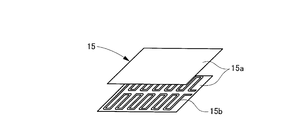
- the mica heater 15 is an electric heater in which a heating resistor (foil) 15b is sandwiched between mica (insulation) plates 15a.
- a heating resistor (foil) 15b is sandwiched between mica (insulation) plates 15a.
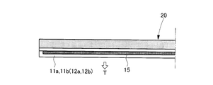
- FIG. 3A shows an example in which vertical and horizontal mica heaters 15 and a heat insulating material 20 for reducing heat loss are embedded in cavities having rectangular cross sections of the upper and lower platens 11a and 11b. Is fastened with bolts to the upper and lower platens 11a and 11b. In this case, it is preferable to join the horizontal mica heater 15 side to the container plates 12a and 12b side. Further, instead of the upper and lower platens 11a and 11b, the mica heater 15 may be attached to the container plates 12a and 12b with the same structure.
- FIG. 3B The example shown in FIG. 3B is an example in which a mica heater 15 is embedded in a cavity having a rectangular cross section of the upper and lower platens 11a and 11b, and a heat insulating material 20 is attached to one surface of the upper and lower platens 11a and 11b.
- the mica heater 15 is sandwiched between the upper and lower members of the upper and lower platens 11a and 11b. In this case, it is preferable to join the mica heater 15 side to the container plates 12a and 12b side. Further, instead of the upper and lower platens 11a and 11b, the mica heater 15 may be attached to the container plates 12a and 12b with the same structure.
- FIGS. 4A and 4B show an example in which the mica heater 15 is fastened with a bolt to one of the upper and lower platens 11a and 11b as a plate. Moreover, you may attach the heat insulating material 20 for heat radiation loss reduction suitably as shown with the chain line in a figure. In addition, instead of the upper and lower platens 11a and 11b, the mica heater 15 may be attached to the container plates 12a and 12b with the same structure.
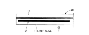
- FIG. 5 shows that the upper and lower platens 11a and 11b are filled with a heat medium (steam, hot water, oil, gas, etc.) 21 in cavities having a rectangular cross section of the upper and lower platens 11a and 11b as plates.
- the mica heater 15 is attached to one surface, and the mica heater 15 is fastened with bolts to the upper and lower platens 11a and 11b. In this case, it is preferable to join the upper and lower platens 11a and 11b directly to the container plates 12a and 12b.
- a heat insulating material 20 for reducing a heat dissipation loss may be appropriately attached.
- the mica heater 15 may be attached to the container plates 12a and 12b with the same structure.
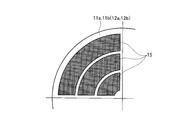
- 6A and 6B are examples of division of the mica heater 15 in the upper and lower platens 11a and 11b described above, and can be divided into various shapes according to zone temperature control or the like. Further, instead of the upper and lower platens 11a and 11b, the mica heater 15 may be attached to the container plates 12a and 12b with the same structure.
- FIGS. 7A and 7B show an example in which a mica heater 15 divided into a plurality of parts in the vertical direction and the circumferential direction is tightened with bolts on the outer peripheral surface of a jacket ring 13 as an outer ring. Moreover, you may attach the heat insulating material 20 for heat radiation loss reduction suitably as shown with the chain line in a figure. Instead of the jacket ring 13, the mica heater 15 may be attached to the segment (including divided segments) 14 side with the same structure.
- FIGS. 8A and 8B show an example in which a heat insulating material 20 and a mica heater 15 divided into a plurality of parts in the vertical direction and the circumferential direction are embedded in a cavity (jacket) of a jacket ring 13 as an outer ring.
- the mica heater 15 is fastened to the jacket ring 13 (located on the inner peripheral side of the cavity) with a bolt. Further, instead of the jacket ring 13, the mica heater 15 may be attached to the segment (including divided segments) 14 side with the same structure.
- FIGS. 9A and 9B show that a mica heater 15 divided into a plurality of parts in the vertical direction and the circumferential direction is fastened with bolts to the outer peripheral surface of a jacket ring 13 as an outer ring, and a cavity (jacket) of the jacket ring 13 is used.
- a heat medium steam, hot water, oil, gas, etc.
- the mica heater 15 is fastened to the jacket ring 13 with a bolt.
- the mica heater 15 may be attached to the segment (including divided segments) 14 side with the same structure.
- the mica heater 15 as the flexible planar heating element is attached to the outer molds such as the upper and lower platens 11a and 11b and the jacket ring 13 of the container 10, and the outer mold (to be heated) )) Directly or via a heating medium, (1) Boilers (heating medium), factory / equipment piping (supply and recovery), piping equipment, and piping work are no longer required, reducing piping heat dissipation (energy) loss, reducing running costs and downsizing the equipment. (2) Since the contact area is large due to the surface heat generation, the power density can be increased and the heating efficiency to the object to be heated is improved, so that the accuracy of the temperature control can be improved and the zone temperature control is possible.
- Mica heaters are inexpensive, thin and have good workability, so they can be heated and mounted in a shape that matches the object to be heated, and the outer mold can be made thinner and the insulation can be made thicker. It is possible to improve the compactness of the device and improve the heat insulation of the mold and make it compatible with existing devices.
- the mica heater is thin (about 1 mm), the heat capacity is small and the power density is higher than that of the rod heater, so the response when heating the heated object is good (the controllability during heating is good)
- Factory steam boilers require constant operation, but with this technology it is possible to control heating while supplying power only to the parts necessary for heating (vulcanizers), so the heating running cost can be reduced. , The following actions and effects can be obtained.
- the present invention is not limited to the above-described embodiments, and various modifications can be made without departing from the gist of the present invention.
- electric heaters other than a mica heater as a flexible planar heating element used for a normal household appliance.
- a flexible sheet heating element used for ordinary household appliances is used in a conventional steam heating type tire vulcanizing apparatus, for example, upper and lower platens 11a and 11b and upper and lower container plates 12a and 12b. You may make it attach partially to the plate etc. which consist of etc.
- the tire vulcanizing apparatus according to the present invention is preferably used for a so-called self-locking tire vulcanizing apparatus in which a container has a function of locking a mold.
Landscapes
- Engineering & Computer Science (AREA)
- Mechanical Engineering (AREA)
- Moulds For Moulding Plastics Or The Like (AREA)
- Heating, Cooling, Or Curing Plastics Or The Like In General (AREA)
Abstract
エネルギーロスとランニングコストの低減と温度コントロール精度向上が図れると共に安価で加工性が良い加熱手段を備えたタイヤ加硫装置を提供する。そのために、上,下プラテン(11a,11b)やジャケットリング(13)等の外金型内に収容された生タイヤ(T)を、当該生タイヤ(T)の外側及び内側から加熱して加硫成形するタイヤ加硫装置において、前記生タイヤ(T)を少なくとも外側から加熱する手段として、前記上,下プラテン(11a,11b)やジャケットリング(13)等の外金型に通常の家庭用電化製品に用いられるマイカヒータ(15)を取り付けて当該外金型を直に又は熱媒体(21)を介して加熱する。
Description
本発明は、本発明は、生タイヤを加硫成形するタイヤ加硫装置に関する。
通常、生タイヤを加硫成形する場合には、内部に生タイヤが充填された外金型(モールド)を加熱媒体により加熱すると共に、生タイヤの内部空間に高温、高圧の加熱媒体を供給することによって、タイヤ内壁面を加熱しながら外金型方向に押圧する。そして、加熱された外金型と生タイヤの内部空間の加熱媒体とで生タイヤを外側及び内側から加熱することにより加硫が行われる。
そして、従来、生タイヤを外側から加熱する手段として、例えば図10に示すようなものがある(特許文献1及び特許文献2参照)。これは、生タイヤTを収容する加硫用金型の外金型と云われるプレートとしての上,下プラテン100a,100bやアウターリングとしてのジャケットリング101等の内部に流路を形成し、これらの流路へ配管ユニット102及び工場母管103を介して工場蒸気ボイラ104から蒸気(加熱媒体)が供給・循環され(図中配管参照)、外金型から熱を生タイヤTに伝えるものである。また、生タイヤTの内部空間(ブラダB内)には、図示しない下部中心機構を介して上述した蒸気が供給・循環されると共に、窒素(N2)ガスや温水等の加熱、加圧媒体が密封されるようにもなっている。
また、他の加熱手段として、外金型の周囲に電磁コイルを配置し、外金型表面を誘導加熱するもの(特許文献3及び特許文献4参照)や外金型に棒状ヒータを埋設し、外金型を間接加熱するもの(特許文献5及び特許文献6参照)がある。
しかしながら、図10に示したような蒸気加熱方式にあっては、蒸気供給配管からの放熱により多大なエネルギーロスが生じるため、ランニングコストが高くなるという問題点があった。また、容易に変更することができない工場母管と加硫機との配管工事が必要となるため、工場レイアウトに非常に困難をきたすとか、蒸気流路内の凝縮ドレンにて上,下プレート間の温度差や温度ムラができるため、ゾーン温度コントロールが困難である等の不具合もあった。
このような背景から、近年では、加硫用金型を加熱するにあたって、蒸気加熱方式を廃止して電気加熱方式に移行する傾向にあり、所謂オール電化をコンセプトに各種のタイヤ加硫装置が開発されているのが業界の現況である。
また、誘導加熱方式にあっては、加硫機の構造やタイヤ金型に合わせて加熱制御(磁力・磁場の調整)するのに多大な時間を要すると共に、電磁コイル取付けや電気絶縁材設置にて装置が大型化してコストアップを招来するという問題点があった。
また、棒状ヒータを使用するものにあっては、加硫用金型に埋設する必要があり、取付け穴とヒータの接触面積が小さいため、加熱効率が低くランニングコストが高くなるという問題点があった。さらに、ヒータ取付け穴(加工)が必要であり、棒状ヒータの配置ピッチが制限されるため、温度均一性、温度コントロール性が悪く、ヒータ自体の熱容量が大きいため昇温に時間を要するという欠点も有する。
そこで、本発明は、エネルギーロスとランニングコストの低減と温度コントロール精度向上が図れると共に安価で加工性が良い加熱手段を備えたタイヤ加硫装置を提供することを目的とする。
斯かる目的を達成するための本発明に係るタイヤ加硫装置は、
外金型内に収容された生タイヤを、当該生タイヤの外側及び内側から加熱して加硫成形するタイヤ加硫装置において、
前記生タイヤを少なくとも外側から加熱する手段として、前記外金型に通常の家庭用電化製品に用いられる可撓性面状発熱体を取り付けて当該外金型を直に又は熱媒体を介して加熱することを特徴とする。
外金型内に収容された生タイヤを、当該生タイヤの外側及び内側から加熱して加硫成形するタイヤ加硫装置において、
前記生タイヤを少なくとも外側から加熱する手段として、前記外金型に通常の家庭用電化製品に用いられる可撓性面状発熱体を取り付けて当該外金型を直に又は熱媒体を介して加熱することを特徴とする。
また、
前記可撓性面状発熱体は、マイカヒータであることを特徴とする。
前記可撓性面状発熱体は、マイカヒータであることを特徴とする。
また、
前記可撓性面状発熱体は、外金型のゾーン温度コントロールに応じて複数に分割されることを特徴とする。
前記可撓性面状発熱体は、外金型のゾーン温度コントロールに応じて複数に分割されることを特徴とする。
また、
前記可撓性面状発熱体は、断熱材と併用して取り付けられることを特徴とする。
前記可撓性面状発熱体は、断熱材と併用して取り付けられることを特徴とする。
また、
前記可撓性面状発熱体は、蒸気加熱式のタイヤ加硫装置において部分的に取り付けられることを特徴とする。
前記可撓性面状発熱体は、蒸気加熱式のタイヤ加硫装置において部分的に取り付けられることを特徴とする。
本発明に係るタイヤ加硫装置によれば、工場蒸気ボイラからの蒸気を使用しないため、エネルギーロスとランニングコストの低減が図れる。また、家庭用電化製品に用いられる可撓性面状発熱体を取り付けるという簡単な手段により、加熱ランニングコストの低減と温度コントロールの精度向上が図れると共に安価で済むという利点が得られる。
以下、本発明に係るタイヤ加硫装置を実施例により図面を用いて詳細に説明する。
図1は本発明の一実施例を示すタイヤ加硫装置の加熱システム図、図2はマイカヒータの取付構造図、図3Aはマイカヒータと断熱材とプラテンの取付構造図、図3Bはマイカヒータと断熱材とプラテンの他の取付構造図、図4Aはマイカヒータとプラテンの取付構造図、図4Bはマイカヒータとプラテンの他の取付構造図、図5はマイカヒータとプラテンと熱媒体の取付構造図、図6Aはプラテンにおけるマイカヒータの分割パターンを示す平面図、図6Bはプラテンにおけるマイカヒータの他の分割パターンを示す平面図、図7Aはマイカヒータとジャケットリングの取付構造を示す平(横)断面図、図7Bはマイカヒータとジャケットリングの取付構造を示す側(縦)断面図、図8Aはマイカヒータと断熱材とジャケットリングの取付構造を示す平(横)断面図、図8Bはマイカヒータと断熱材とジャケットリングの取付構造を示す側(縦)断面図、図9Aはマイカヒータと熱媒体とジャケットリングの取付構造を示す平(横)断面図、図9Bはマイカヒータと熱媒体とジャケットリングの取付構造を示す側(縦)断面図である。
図1に示すように、タイヤ加硫装置のコンテナ10は、上,下プラテン11a,11b及び上,下コンテナプレート12a,12b等からなるプレートと、ジャケットリング13及びセグメント(分割セグメントを含む)14等からなるアウターリングとを有し、これらは通称、外金型と呼ばれる。そして、この外金型の内部に、トレッド型部Ma、上,下サイドウォール型部Mb,Mc、上,下ビードリングMd,Me(これらは通称、割金型と呼ばれる)介して生タイヤTが収容される。
また、生タイヤTの内部空間には、公知のブラダBが挿入され、このブラダB内に図示しない下部中心機構を介して蒸気が供給・循環されると共に、窒素(N2)ガスや温水等の加熱、加圧媒体が密封されるようにもなっている。
従って、上述した外金型を後述する加熱手段により加熱すると共に、上述したブラダB内に高温、高圧の加熱媒体を供給してタイヤ内壁面を加熱しながら外金型方向に押圧することによって、加熱された外金型とブラダB内の加熱媒体とで生タイヤTが外側及び内側から加熱されて加硫が行われる。
そして、本実施例では、上述した外金型の内、上,下プラテン11a,11bとジャケットリング13に、可撓性面状発熱体としてのマイカヒータ15が後述する各種の取付構造により取り付けられ、各々家庭用電化製品に用いられる熱源に相当するヒータ電源16A,16Bから給電線17A,17Bを介して電力が供給されて、当該上,下プラテン11a,11bとジャケットリング13を直に又は熱媒体(蒸気、温水、オイル、ガス等)を介して加熱されるようになっている。
マイカヒータ15は、図2に示すように、マイカ(絶縁)板15aで発熱抵抗体(箔)15bを挟んだ電気ヒータで、(1)電気絶縁性、耐熱性(~600℃)、耐圧縮性、可撓性、耐水性、耐薬品性に優れる、(2)高温時の発煙・臭気・ガス発生・マイカふくれが少ない、(3)打抜・加工性に優れる、(4)ワット密度が高く、薄い(厚み1mm程度→熱容量が小さい)ので、高速昇温が可能である(レスポンス性が良好)、(4)面状発熱体のため、加熱効率が良好(接触面積が大)であり、発熱が均一(温度分布が均一)である等の特徴を有し、ホットプレート、ポット、電子ジャーの加熱・予熱等家電機器に使用されている。
次に、マイカヒータ15の各種取付構造を説明する。
図3Aに示すものは、プレートとしての上,下プラテン11a,11bの断面矩形状の空洞内に縦,横のマイカヒータ15と放熱ロス低減のための断熱材20を埋設した例であり、マイカヒータ15は上,下プラテン11a,11bに対しボルトで締め付けられる。この場合、横のマイカヒータ15側をコンテナプレート12a,12b側に接合すると好適である。また、上,下プラテン11a,11bに代えてコンテナプレート12a,12b側に同様の構造でマイカヒータ15を取り付けても良い。
図3Aに示すものは、プレートとしての上,下プラテン11a,11bの断面矩形状の空洞内に縦,横のマイカヒータ15と放熱ロス低減のための断熱材20を埋設した例であり、マイカヒータ15は上,下プラテン11a,11bに対しボルトで締め付けられる。この場合、横のマイカヒータ15側をコンテナプレート12a,12b側に接合すると好適である。また、上,下プラテン11a,11bに代えてコンテナプレート12a,12b側に同様の構造でマイカヒータ15を取り付けても良い。
図3Bに示すものは、プレートとしての上,下プラテン11a,11bの断面矩形状の空洞内にマイカヒータ15を埋設すると共に、上,下プラテン11a,11bの一面に断熱材20を貼付した例であり、マイカヒータ15は上,下プラテン11a,11bの分割された上,下部材間に挟み込まれる。この場合、マイカヒータ15側をコンテナプレート12a,12b側に接合すると好適である。また、上,下プラテン11a,11bに代えてコンテナプレート12a,12b側に同様の構造でマイカヒータ15を取り付けても良い。
図4A及び図4Bに示すものは、プレートとしての上,下プラテン11a,11bのいずれか一面にマイカヒータ15をボルトで締め付けた例である。また、図中鎖線で示すように放熱ロス低減のための断熱材20を適宜取り付けても良い。尚、上,下プラテン11a,11bに代えてコンテナプレート12a,12b側に同様の構造でマイカヒータ15を取り付けても良い。
図5に示すものは、プレートとしての上,下プラテン11a,11bの断面矩形状の空洞内に熱媒体(蒸気、温水、オイル、ガス等)21を充填すると共に、上,下プラテン11a,11bの一面にマイカヒータ15を取り付けた例であり、マイカヒータ15は上,下プラテン11a,11bに対しボルトで締め付けられる。この場合、上,下プラテン11a,11b側を直にコンテナプレート12a,12bに接合すると好適である。図中鎖線で示すように放熱ロス低減のための断熱材20を適宜取り付けても良い。尚、上,下プラテン11a,11bに代えてコンテナプレート12a,12b側に同様の構造でマイカヒータ15を取り付けても良い。
図6A及び図6Bに示すものは、上述した上,下プラテン11a,11bにおけるマイカヒータ15の分割例であり、ゾーン温度コントロール等に応じて各種形状に分割可能である。また、上,下プラテン11a,11bに代えてコンテナプレート12a,12b側に同様の構造でマイカヒータ15を取り付けても良い。
図7A及び図7Bに示すものは、アウターリングとしてのジャケットリング13の外周面に上下方向及び円周方向に複数個に分割されたマイカヒータ15をボルトで締め付けた例である。また、図中鎖線で示すように放熱ロス低減のための断熱材20を適宜取り付けても良い。尚、ジャケットリング13に代えてセグメント(分割セグメントを含む)14側に同様の構造でマイカヒータ15を取り付けても良い。
図8A及び図8Bに示すものは、アウターリングとしてのジャケットリング13の空洞(ジャケット)内に断熱材20と上下方向及び円周方向に複数個に分割されたマイカヒータ15とを埋設した例である。マイカヒータ15はジャケットリング13に対し(空洞の内周側に位置して)ボルトで締め付けられる。また、ジャケットリング13に代えてセグメント(分割セグメントを含む)14側に同様の構造でマイカヒータ15を取り付けても良い。
図9A及び図9Bに示すものは、アウターリングとしてのジャケットリング13の外周面に上下方向及び円周方向に複数個に分割されたマイカヒータ15をボルトで締め付けると共に、ジャケットリング13の空洞(ジャケット)内に熱媒体(蒸気、温水、オイル、ガス等)21を充填した例である。マイカヒータ15はジャケットリング13に対しボルトで締め付けられる。また、図中鎖線で示すように放熱ロス低減のための断熱材20を適宜取り付けても良い。尚、ジャケットリング13に代えてセグメント(分割セグメントを含む)14側に同様の構造でマイカヒータ15を取り付けても良い。
このように本実施例では、コンテナ10の上,下プラテン11a,11bとジャケットリング13等の外金型に、可撓性面状発熱体としてのマイカヒータ15を取り付け、当該外金型(被加熱物)を直に又は熱媒体を介して加熱するようにしたので、
(1)ボイラ(加熱媒体)、工場/装置の配管(供給、回収)、配管機器、配管工事が不要となり、配管放熱(エネルギー)ロスの低減によるランニングコスト低減と装置のコンパクト化が図れる、
(2)面状発熱により、接触面積が大きいため、電力密度を大きくすることができ、被加熱物への加熱効率が良くなるので、温度コントロールの精度向上が図れると共に、ゾーン温度コントロールが可能となる、
(3)マイカヒータは、安価で薄く加工性が良いため、被加熱物に合わせた形状で加熱、取付けが可能となると共に外金型の薄肉化や断熱材の厚肉化が可能となり、メンテナンス性が良く、装置のコンパクト化が図れると共に、金型の断熱性の向上と既存装置との互換が可能となる、
(4)マイカヒータは、薄い(1mm程度)ため熱容量が小さく、棒状ヒータに比べ電力密度が高いので、被加熱物昇温時のレスポンス性が良い(加熱時の制御性が良い)、
(5)工場蒸気ボイラでは常時運転が必要であるが、本技術では加熱に必要な部分(加硫機)だけ電力供給しながら加熱制御することが可能であるため、加熱ランニングコストの低減が図れる、
等の作用・効果が得られる。
(1)ボイラ(加熱媒体)、工場/装置の配管(供給、回収)、配管機器、配管工事が不要となり、配管放熱(エネルギー)ロスの低減によるランニングコスト低減と装置のコンパクト化が図れる、
(2)面状発熱により、接触面積が大きいため、電力密度を大きくすることができ、被加熱物への加熱効率が良くなるので、温度コントロールの精度向上が図れると共に、ゾーン温度コントロールが可能となる、
(3)マイカヒータは、安価で薄く加工性が良いため、被加熱物に合わせた形状で加熱、取付けが可能となると共に外金型の薄肉化や断熱材の厚肉化が可能となり、メンテナンス性が良く、装置のコンパクト化が図れると共に、金型の断熱性の向上と既存装置との互換が可能となる、
(4)マイカヒータは、薄い(1mm程度)ため熱容量が小さく、棒状ヒータに比べ電力密度が高いので、被加熱物昇温時のレスポンス性が良い(加熱時の制御性が良い)、
(5)工場蒸気ボイラでは常時運転が必要であるが、本技術では加熱に必要な部分(加硫機)だけ電力供給しながら加熱制御することが可能であるため、加熱ランニングコストの低減が図れる、
等の作用・効果が得られる。
尚、本発明は上記実施例に限定されず、本発明の要旨を逸脱しない範囲で各種変更が可能であることはいうまでもない。例えば、通常の家庭用電化製品に用いられる可撓性面状発熱体としてマイカヒータ以外の電気ヒータを用いても良い。また、通常の家庭用電化製品に用いられる可撓性面状発熱体を、従前からある蒸気加熱式のタイヤ加硫装置において、例えば上,下プラテン11a,11b及び上,下コンテナプレート12a,12b等からなるプレート等に部分的に取り付けるようにしても良い。
本発明に係るタイヤ加硫装置は、コンテナに金型をロックする機能を持たせた、所謂セルフロック式のタイヤ加硫装置に用いると好適である。
10 コンテナ
11a,11b 上,下プラテン
12a,12b 上,下コンテナプレート
13 ジャケットリング
14 セグメント(分割セグメントを含む)
15 マイカヒータ
16A,16B ヒータ電源
17A,17B 給電線
20 断熱材
21 熱媒体(蒸気、温水、オイル、ガス等)
T 生タイヤ
B ブラダ
11a,11b 上,下プラテン
12a,12b 上,下コンテナプレート
13 ジャケットリング
14 セグメント(分割セグメントを含む)
15 マイカヒータ
16A,16B ヒータ電源
17A,17B 給電線
20 断熱材
21 熱媒体(蒸気、温水、オイル、ガス等)
T 生タイヤ
B ブラダ
Claims (12)
- 外金型内に収容された生タイヤを、当該生タイヤの外側及び内側から加熱して加硫成形するタイヤ加硫装置において、
前記生タイヤを少なくとも外側から加熱する手段として、前記外金型に通常の家庭用電化製品に用いられる可撓性面状発熱体を取り付けて当該外金型を直に又は熱媒体を介して加熱することを特徴とするタイヤ加硫装置。 - 前記可撓性面状発熱体は、マイカヒータであることを特徴とする請求項1に記載のタイヤ加硫装置。
- 前記可撓性面状発熱体は、外金型のゾーン温度コントロールに応じて複数に分割されることを特徴とする請求項1又は2に記載のタイヤ加硫装置。
- 前記可撓性面状発熱体は、断熱材と併用して取り付けられることを特徴とする請求項1に記載のタイヤ加硫装置。
- 前記可撓性面状発熱体は、断熱材と併用して取り付けられることを特徴とする請求項2に記載のタイヤ加硫装置。
- 前記可撓性面状発熱体は、断熱材と併用して取り付けられることを特徴とする請求項3に記載のタイヤ加硫装置。
- 前記可撓性面状発熱体は、蒸気加熱式のタイヤ加硫装置において部分的に取り付けられることを特徴とする請求項1に記載のタイヤ加硫装置。
- 前記可撓性面状発熱体は、蒸気加熱式のタイヤ加硫装置において部分的に取り付けられることを特徴とする請求項2に記載のタイヤ加硫装置。
- 前記可撓性面状発熱体は、蒸気加熱式のタイヤ加硫装置において部分的に取り付けられることを特徴とする請求項3に記載のタイヤ加硫装置。
- 前記可撓性面状発熱体は、蒸気加熱式のタイヤ加硫装置において部分的に取り付けられることを特徴とする請求項4に記載のタイヤ加硫装置。
- 前記可撓性面状発熱体は、蒸気加熱式のタイヤ加硫装置において部分的に取り付けられることを特徴とする請求項5に記載のタイヤ加硫装置。
- 前記可撓性面状発熱体は、蒸気加熱式のタイヤ加硫装置において部分的に取り付けられることを特徴とする請求項6に記載のタイヤ加硫装置。
Priority Applications (1)
| Application Number | Priority Date | Filing Date | Title |
|---|---|---|---|
| PCT/JP2011/057953 WO2012131929A1 (ja) | 2011-03-30 | 2011-03-30 | タイヤ加硫装置 |
Applications Claiming Priority (1)
| Application Number | Priority Date | Filing Date | Title |
|---|---|---|---|
| PCT/JP2011/057953 WO2012131929A1 (ja) | 2011-03-30 | 2011-03-30 | タイヤ加硫装置 |
Publications (1)
| Publication Number | Publication Date |
|---|---|
| WO2012131929A1 true WO2012131929A1 (ja) | 2012-10-04 |
Family
ID=46929755
Family Applications (1)
| Application Number | Title | Priority Date | Filing Date |
|---|---|---|---|
| PCT/JP2011/057953 Ceased WO2012131929A1 (ja) | 2011-03-30 | 2011-03-30 | タイヤ加硫装置 |
Country Status (1)
| Country | Link |
|---|---|
| WO (1) | WO2012131929A1 (ja) |
Cited By (1)
| Publication number | Priority date | Publication date | Assignee | Title |
|---|---|---|---|---|
| CN111669848A (zh) * | 2019-03-08 | 2020-09-15 | 深圳市杰世达科技有限公司 | 一种节能电热装置 |
Citations (9)
| Publication number | Priority date | Publication date | Assignee | Title |
|---|---|---|---|---|
| JPH0768557A (ja) * | 1993-08-31 | 1995-03-14 | Tokai Rubber Ind Ltd | 薄肉ゴムベルトの加硫成形型及び薄肉ゴムベルトの製造方法 |
| JPH11320567A (ja) * | 1998-05-11 | 1999-11-24 | Bridgestone Corp | タイヤ加硫装置および加硫方法 |
| JP2000000823A (ja) * | 1998-06-12 | 2000-01-07 | Komatsu Ltd | 面状ヒーター加熱金型 |
| JP2000043047A (ja) * | 1998-07-28 | 2000-02-15 | Sumitomo Rubber Ind Ltd | タイヤの加硫方法、加硫装置及びそれを用いて加硫されたタイヤ |
| JP2000271969A (ja) * | 1999-03-26 | 2000-10-03 | Sekisui Chem Co Ltd | 射出成形用金型 |
| JP2003231126A (ja) * | 2002-02-12 | 2003-08-19 | Yokohama Rubber Co Ltd:The | タイヤ加硫用コンテナー |
| JP2005528256A (ja) * | 2002-05-31 | 2005-09-22 | ピレリ・プネウマティチ・ソチエタ・ペル・アツィオーニ | タイヤの製造方法およびかかる方法を実行するためのトロイダル支持体 |
| WO2008146359A1 (ja) * | 2007-05-29 | 2008-12-04 | Hirata Corporation | モールドコンテナおよびタイヤ加硫装置 |
| JP2009023192A (ja) * | 2007-07-19 | 2009-02-05 | Omron Corp | ヒータの取付け構造 |
-
2011
- 2011-03-30 WO PCT/JP2011/057953 patent/WO2012131929A1/ja not_active Ceased
Patent Citations (9)
| Publication number | Priority date | Publication date | Assignee | Title |
|---|---|---|---|---|
| JPH0768557A (ja) * | 1993-08-31 | 1995-03-14 | Tokai Rubber Ind Ltd | 薄肉ゴムベルトの加硫成形型及び薄肉ゴムベルトの製造方法 |
| JPH11320567A (ja) * | 1998-05-11 | 1999-11-24 | Bridgestone Corp | タイヤ加硫装置および加硫方法 |
| JP2000000823A (ja) * | 1998-06-12 | 2000-01-07 | Komatsu Ltd | 面状ヒーター加熱金型 |
| JP2000043047A (ja) * | 1998-07-28 | 2000-02-15 | Sumitomo Rubber Ind Ltd | タイヤの加硫方法、加硫装置及びそれを用いて加硫されたタイヤ |
| JP2000271969A (ja) * | 1999-03-26 | 2000-10-03 | Sekisui Chem Co Ltd | 射出成形用金型 |
| JP2003231126A (ja) * | 2002-02-12 | 2003-08-19 | Yokohama Rubber Co Ltd:The | タイヤ加硫用コンテナー |
| JP2005528256A (ja) * | 2002-05-31 | 2005-09-22 | ピレリ・プネウマティチ・ソチエタ・ペル・アツィオーニ | タイヤの製造方法およびかかる方法を実行するためのトロイダル支持体 |
| WO2008146359A1 (ja) * | 2007-05-29 | 2008-12-04 | Hirata Corporation | モールドコンテナおよびタイヤ加硫装置 |
| JP2009023192A (ja) * | 2007-07-19 | 2009-02-05 | Omron Corp | ヒータの取付け構造 |
Cited By (1)
| Publication number | Priority date | Publication date | Assignee | Title |
|---|---|---|---|---|
| CN111669848A (zh) * | 2019-03-08 | 2020-09-15 | 深圳市杰世达科技有限公司 | 一种节能电热装置 |
Similar Documents
| Publication | Publication Date | Title |
|---|---|---|
| JP5582906B2 (ja) | タイヤ用加硫モールドの加熱装置および加熱方法 | |
| US8941036B2 (en) | Heating unit, tire heating apparatus, and method for remodeling tire mold | |
| JP5467774B2 (ja) | タイヤ加硫機 | |
| JP2011126044A (ja) | タイヤ加硫装置 | |
| JP4786620B2 (ja) | 加熱ユニット及びタイヤ加熱装置 | |
| CN103538188A (zh) | 轮胎硫化外模具电磁感应加热装置 | |
| JP5457099B2 (ja) | 金型の加熱構造 | |
| CN108312398B (zh) | 电磁硫化系统 | |
| KR20170112140A (ko) | 프리캐스트 부재 양생 장치 | |
| CN203863888U (zh) | 斜交轮胎的微波硫化装置 | |
| CN207825511U (zh) | 一种分段加热轮胎模具 | |
| CN113878911A (zh) | 用于为蒸锅式轮胎硫化机的外模供热的电加热装置 | |
| US20150104536A1 (en) | Molding device | |
| CN108136628B (zh) | 固化方法和装置 | |
| CN105034454A (zh) | 瓦楞纸辊 | |
| CN202192746U (zh) | 用于转盘机上的电磁加热装置 | |
| CN103737682A (zh) | 一种薄板压贴机 | |
| KR20170097181A (ko) | 타이어 예열 장치, 타이어 가황 시스템, 타이어 예열 방법, 및 타이어 제조 방법 | |
| KR100528541B1 (ko) | 타이어 가류금형 | |
| KR101200031B1 (ko) | 타이어 가류기의 전열 성형드럼 | |
| KR20030043245A (ko) | 유도 가열식 가류기 | |
| TW201242743A (en) | Tire vulcanizing apparatus | |
| CN100513115C (zh) | 硫化机电加热装置 | |
| CN109454783B (zh) | 一种硫化恒温加热平台 | |
| CN121105452A (zh) | 一种轮胎硫化机热板电磁感应加热装备 |
Legal Events
| Date | Code | Title | Description |
|---|---|---|---|
| 121 | Ep: the epo has been informed by wipo that ep was designated in this application |
Ref document number: 11862595 Country of ref document: EP Kind code of ref document: A1 |
|
| NENP | Non-entry into the national phase |
Ref country code: DE |
|
| 122 | Ep: pct application non-entry in european phase |
Ref document number: 11862595 Country of ref document: EP Kind code of ref document: A1 |
|
| NENP | Non-entry into the national phase |
Ref country code: JP |