WO2012128283A1 - コネクタ - Google Patents
コネクタ Download PDFInfo
- Publication number
- WO2012128283A1 WO2012128283A1 PCT/JP2012/057177 JP2012057177W WO2012128283A1 WO 2012128283 A1 WO2012128283 A1 WO 2012128283A1 JP 2012057177 W JP2012057177 W JP 2012057177W WO 2012128283 A1 WO2012128283 A1 WO 2012128283A1
- Authority
- WO
- WIPO (PCT)
- Prior art keywords
- terminal
- accommodating chamber
- locking lance
- connector
- lance
- Prior art date
- Legal status (The legal status is an assumption and is not a legal conclusion. Google has not performed a legal analysis and makes no representation as to the accuracy of the status listed.)
- Ceased
Links
Images


Classifications
-
- H—ELECTRICITY
- H01—ELECTRIC ELEMENTS
- H01R—ELECTRICALLY-CONDUCTIVE CONNECTIONS; STRUCTURAL ASSOCIATIONS OF A PLURALITY OF MUTUALLY-INSULATED ELECTRICAL CONNECTING ELEMENTS; COUPLING DEVICES; CURRENT COLLECTORS
- H01R13/00—Details of coupling devices of the kinds covered by groups H01R12/70 or H01R24/00 - H01R33/00
- H01R13/40—Securing contact members in or to a base or case; Insulating of contact members
- H01R13/42—Securing in a demountable manner
-
- H—ELECTRICITY
- H01—ELECTRIC ELEMENTS
- H01R—ELECTRICALLY-CONDUCTIVE CONNECTIONS; STRUCTURAL ASSOCIATIONS OF A PLURALITY OF MUTUALLY-INSULATED ELECTRICAL CONNECTING ELEMENTS; COUPLING DEVICES; CURRENT COLLECTORS
- H01R13/00—Details of coupling devices of the kinds covered by groups H01R12/70 or H01R24/00 - H01R33/00
- H01R13/62—Means for facilitating engagement or disengagement of coupling parts or for holding them in engagement
- H01R13/627—Snap or like fastening
- H01R13/6278—Snap or like fastening comprising a pin snapping into a recess
-
- H—ELECTRICITY
- H01—ELECTRIC ELEMENTS
- H01R—ELECTRICALLY-CONDUCTIVE CONNECTIONS; STRUCTURAL ASSOCIATIONS OF A PLURALITY OF MUTUALLY-INSULATED ELECTRICAL CONNECTING ELEMENTS; COUPLING DEVICES; CURRENT COLLECTORS
- H01R13/00—Details of coupling devices of the kinds covered by groups H01R12/70 or H01R24/00 - H01R33/00
- H01R13/40—Securing contact members in or to a base or case; Insulating of contact members
- H01R13/42—Securing in a demountable manner
- H01R13/422—Securing in resilient one-piece base or case, e.g. by friction; One-piece base or case formed with resilient locking means
- H01R13/4223—Securing in resilient one-piece base or case, e.g. by friction; One-piece base or case formed with resilient locking means comprising integral flexible contact retaining fingers
-
- H—ELECTRICITY
- H01—ELECTRIC ELEMENTS
- H01R—ELECTRICALLY-CONDUCTIVE CONNECTIONS; STRUCTURAL ASSOCIATIONS OF A PLURALITY OF MUTUALLY-INSULATED ELECTRICAL CONNECTING ELEMENTS; COUPLING DEVICES; CURRENT COLLECTORS
- H01R43/00—Apparatus or processes specially adapted for manufacturing, assembling, maintaining, or repairing of line connectors or current collectors or for joining electric conductors
- H01R43/20—Apparatus or processes specially adapted for manufacturing, assembling, maintaining, or repairing of line connectors or current collectors or for joining electric conductors for assembling or disassembling contact members with insulating base, case or sleeve
Definitions
- the present invention relates to a connector.
- a terminal lance for preventing the rearward removal from the terminal accommodating chamber in the connector housing has been provided, and this terminal lance has a folded portion bent in the width direction of the terminal connecting portion. It is known that it is bent at a predetermined angle in the outer direction over the entire width (for example, see Patent Document 1).
- the terminal lance When this terminal is inserted into the terminal housing chamber of the connector housing, the terminal lance is bent downward by the ceiling wall, and when positioned at a predetermined position, the terminal lance is restored upward, and the rear end of the terminal lance is By engaging with a locking step provided on the ceiling wall, the terminal can be prevented from coming off from the terminal accommodating chamber.
- the terminal since the terminal is provided with a terminal lance as a locking lance, the locking lance has rigidity and the terminal insertion force into the terminal accommodating chamber is increased. It was. Further, when taking out the terminal from the terminal accommodating chamber, the locking lance of the terminal which is a conducting member must be bent by a release jig or the like, and workability is lowered, for example, when the work is carefully performed.
- the terminal is provided with an engaged portion made of a hole such as a lance hole, and the locking lance is engaged with the engaged portion of the terminal.
- An engagement protrusion is provided.
- the connector is provided with a pair of terminal support portions for supporting the lower surface sides on both sides in the width direction on the connection portion side of the terminal on both side walls of the terminal accommodating chamber, and the locking lance is bent between the pair of support portions. It is provided as possible.
- an object of the present invention is to provide a connector that can improve the locking of the terminal by the locking lance and improve the support stability of the terminal in the terminal accommodating chamber.
- the present invention includes a terminal accommodating chamber in which a terminal is accommodated and a connection portion side of the terminal is opened, a terminal support portion that is provided on the opening side of the terminal accommodating chamber and supports the lower surface side of the terminal, and the terminal accommodating chamber.
- a locking lance that is provided so as to be able to bend and that is locked to the terminal, and an engaged protrusion that protrudes downward from the terminal support portion in a state that the terminal is supported by the terminal support portion has a full width.
- the locking lance is provided below the terminal support portion and is provided with an engaging portion that engages with the engaged protrusion, and the engaging portion extends over the entire width of the terminal.
- a connector characterized by being provided.
- an engaged protrusion that protrudes downward from the terminal support portion while being supported by the terminal support portion is provided over the entire width of the terminal, and the locking lance is positioned below the terminal support portion and engaged. Since the engaging portion that engages with the mating protrusion is provided on the locking lance, the terminal support by the terminal support portion and the terminal locking by the locking lance can be set independently. For this reason, the freedom degree of design of a terminal support part improves, and the support stability of the terminal in a terminal storage chamber can be improved.
- the engaging portion of the locking lance is provided over the entire width of the terminal, the engagement between the engaged protrusion of the terminal and the engaging portion of the locking lance can be performed in a wide range.
- the terminal can be reliably prevented from coming off from the terminal accommodating chamber.
- the terminal support portion is provided over the entire width of the terminal accommodating chamber.
- the terminal support portion is provided over the entire width of the terminal accommodating chamber, the terminal can be supported by the terminal supporting portion even if the terminal is moved in the terminal accommodating chamber.
- the terminal support stability can be further improved.
- FIGS. 1 to 3B A connector according to an embodiment of the present invention will be described with reference to FIGS. 1 to 3B.
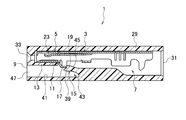
- the connector 1 accommodates a terminal 3 and has a terminal accommodating chamber 7 in which the connecting portion 5 side of the terminal 3 is opened, and an opening 9 side of the terminal accommodating chamber 7 and is provided on the lower surface 11 side of the terminal 3. And a locking lance 15 provided in the terminal accommodating chamber 7 so as to be able to bend and locked to the terminal 3.
- the terminal 3 is provided with an engaged protrusion 17 that extends downward from the terminal support 13 while being supported by the terminal support 13, and the locking lance 15 is connected to the terminal support 13.
- An engaging portion 19 that is positioned further downward and engages with the engaged protrusion 17 is provided, and the engaging portion 19 is provided over the entire width of the terminal 3.
- terminal support portion 13 is provided over the entire width of the terminal accommodating chamber 7.
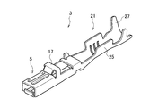
- the terminal 3 is made of a conductive material, and includes a connection portion 5, a wire fixing portion 21, and an engaged protrusion 17.
- the connecting portion 5 has a spring 23 (see FIG. 2) that can be elastically deformed.
- a connecting portion such as a tab of a mating terminal (not shown) is inserted into the connecting portion 5 and is elastically contacted with the spring 23, so that the terminal 3 and the mating terminal are electrically connected.
- the electric wire fixing part 21 has a core wire fixing part 25 in which a core wire of a covered electric wire (not shown) is conducted and caulked, and a covered fixing part 27 for caulking the covered part of the covered electric wire and fixing the covered electric wire.
- a covered electric wire By fixing the covered electric wire to the electric wire fixing portion 21, an electronic component (not shown) connected to the covered electric wire and the terminal 3 are electrically connected.
- the engaged protrusion 17 is provided over the entire width on the connecting portion 5 side. As shown in FIG. 2, the protruding length of the engaged protrusion 17 is set so as to be positioned below the terminal support portion 13 in a state where the terminal 3 is accommodated in the terminal accommodating chamber 7. . Such a terminal 3 is accommodated in the terminal accommodating chamber 7.
- the terminal accommodating chamber 7 extends in the length direction of the housing 29, the terminal 3 is inserted from the insertion port 31 side, and the connection of the terminal 3 to the opening 9 side is performed.
- the part 5 side is arranged.
- the housing 29 is fitted to a mating housing (not shown), so that the connection portion such as a tab of the mating terminal is connected from the connection portion insertion port 33 on the opening 9 side. Is inserted, and the connecting portion 5 of the terminal 3 and the mating terminal are connected.
- the connection part 5 side of the terminal 3 accommodated in the terminal accommodation chamber 7 is supported by the terminal support part 13.
- the terminal support portion 13 is provided as one member continuous with the housing 29 from both side walls 35, 37 over the entire width of the terminal accommodating chamber 7, and the engaged protrusion 17 of the terminal 3 in the length direction from the opening 9 side. It extends to the part where is located.
- the terminal support portion 13 supports the lower surface 11 side of the terminal 3 on the connection portion 5 side in a state where the terminal 3 is accommodated in the terminal accommodating chamber 7.
- a locking lance 15 is provided below the terminal support portion 13.
- the locking lance 15 is provided in a flexible space 43 formed between the lower surface 39 and the inner wall surface 41 of the terminal accommodating chamber 7 so that it can be bent.
- the locking lance 15 is positioned below the terminal support portion 13, and when the terminal 3 is accommodated in the terminal accommodating chamber 7 from the insertion port 31 side, the inclined surface 45 is an engaged protrusion of the terminal 3. It is bent downward by contacting with 17.
- the terminal 3 is inserted toward the opening 9 from this state and the lower surface 11 side of the terminal 3 on the connection portion 5 side is supported by the terminal support portion 13, the locking lance 15 is restored upward. At this time, an engaging portion 19 that is engaged with the engaged protrusion 17 of the terminal 3 is provided on the locking lance 15.
- the engaging portion 19 is provided over the entire width of the terminal 3 so as to engage with the entire width of the engaged protrusion 17 of the terminal 3 in the locking lance 15.
- the engaging portion 19 is engaged with the engaged protrusion 17 of the terminal 3 by restoring the locking lance 15 upward, and the terminal 3 is accommodated in the terminal accommodating space. Preventing from exiting the chamber 7.
- the engagement between the engagement portion 19 of the locking lance 15 and the engaged protrusion 17 of the terminal 3 is performed by inserting a release jig (not shown) from the jig insertion port 47 provided on the opening 9 side.
- the terminal 3 can be taken out from the terminal accommodating chamber 7 by releasing the locking lance 15 by bending the locking lance 15 downward by contacting the tip of the locking lance 15.
- a regulating member such as a spacer is inserted from the jig insertion port 47 and disposed in the flexible space 43, and below the locking lance 15. , And the engagement between the engaged protrusion 17 and the engagement portion 19 is prevented from being released.
- an engaged protrusion 17 that protrudes downward from the terminal support 13 while being supported by the terminal support 13 is provided over the entire width of the terminal 3, and the locking lance 15 is supported by the terminal. Since the engaging lance 15 that is located below the portion 13 and engages the engaged protrusion 17 is provided on the locking lance 15, the terminal 3 is supported by the terminal support portion 13 and the terminal 3 by the locking lance 15. Can be set independently of each other. For this reason, the freedom degree of design of the terminal support part 13 improves, and the support stability of the terminal 3 in the terminal storage chamber 7 can be improved.
- the engaging portion 19 of the locking lance 15 is provided over the entire width of the terminal 3, the engagement between the engaged protrusion 17 of the terminal 3 and the engaging portion 19 of the locking lance 15 is made. This can be performed in a wide range, and the terminal 3 can be reliably prevented from coming off from the terminal accommodating chamber 7.
- the terminal support part 13 is provided over the full width of the terminal accommodating chamber 7, even if the terminal 3 is moved in the terminal accommodating chamber 7, the terminal supporting part 13 can support the terminal 3. It is possible to further improve the support stability of the terminal 3 in the terminal accommodating chamber 7.
- the housing has a configuration in which only one terminal accommodating chamber is provided.
- the present invention is not limited to this, and the housing has a plurality of terminal accommodating chambers.
- the configuration of the present invention can also be applied.
Landscapes
- Connector Housings Or Holding Contact Members (AREA)
Abstract
Description
3…端子
5…接続部
7…端子収容室
9…開口
11…端子の下面
13…端子支持部
15…係止ランス
17…被係合突部
19…係合部
Claims (2)
- 端子を収容しこの端子の接続部側が開口された端子収容室と、
この端子収容室の開口側に設けられ前記端子の下面側を支持する端子支持部と、
前記端子収容室内に撓み可能に設けられ前記端子に係止される係止ランスと、
を備え、
前記端子には、前記端子支持部に支持された状態で前記端子支持部より下方に突出する被係合突部が全幅に亘って設けられ、
前記係止ランスには、前記端子支持部より下方に位置され前記被係合突部と係合する係合部が設けられ、
前記係合部は、前記端子の全幅に亘って設けられていることを特徴とするコネクタ。 - 前記端子支持部は、前記端子収容室の全幅に亘って設けられていることを特徴とする請求項1記載のコネクタ。
Priority Applications (4)
| Application Number | Priority Date | Filing Date | Title |
|---|---|---|---|
| CN2012800136299A CN103444004A (zh) | 2011-03-23 | 2012-03-21 | 连接器 |
| KR1020137027616A KR20140002764A (ko) | 2011-03-23 | 2012-03-21 | 커넥터 |
| DE112012001374T DE112012001374T5 (de) | 2011-03-23 | 2012-03-21 | Steckverbinder |
| US14/031,337 US20140017929A1 (en) | 2011-03-23 | 2013-09-19 | Connector |
Applications Claiming Priority (2)
| Application Number | Priority Date | Filing Date | Title |
|---|---|---|---|
| JP2011-063932 | 2011-03-23 | ||
| JP2011063932A JP2012199190A (ja) | 2011-03-23 | 2011-03-23 | コネクタ |
Related Child Applications (1)
| Application Number | Title | Priority Date | Filing Date |
|---|---|---|---|
| US14/031,337 Continuation US20140017929A1 (en) | 2011-03-23 | 2013-09-19 | Connector |
Publications (1)
| Publication Number | Publication Date |
|---|---|
| WO2012128283A1 true WO2012128283A1 (ja) | 2012-09-27 |
Family
ID=46879425
Family Applications (1)
| Application Number | Title | Priority Date | Filing Date |
|---|---|---|---|
| PCT/JP2012/057177 Ceased WO2012128283A1 (ja) | 2011-03-23 | 2012-03-21 | コネクタ |
Country Status (6)
| Country | Link |
|---|---|
| US (1) | US20140017929A1 (ja) |
| JP (1) | JP2012199190A (ja) |
| KR (1) | KR20140002764A (ja) |
| CN (1) | CN103444004A (ja) |
| DE (1) | DE112012001374T5 (ja) |
| WO (1) | WO2012128283A1 (ja) |
Families Citing this family (5)
| Publication number | Priority date | Publication date | Assignee | Title |
|---|---|---|---|---|
| JP2012186115A (ja) * | 2011-03-08 | 2012-09-27 | Yazaki Corp | コネクタ |
| JP6141612B2 (ja) * | 2012-09-21 | 2017-06-07 | 矢崎総業株式会社 | コネクタ |
| US9318836B2 (en) * | 2014-02-06 | 2016-04-19 | Dai-Ichi Seiko Co., Ltd. | Electric connector |
| JP6087335B2 (ja) * | 2014-11-28 | 2017-03-01 | 矢崎総業株式会社 | コネクタ |
| JP6754392B2 (ja) | 2018-05-23 | 2020-09-09 | 矢崎総業株式会社 | コネクタ |
Citations (3)
| Publication number | Priority date | Publication date | Assignee | Title |
|---|---|---|---|---|
| JPS5871986U (ja) * | 1981-11-10 | 1983-05-16 | 三菱自動車工業株式会社 | 電子機器用コネクタ |
| JPH04109574A (ja) * | 1989-12-15 | 1992-04-10 | Amp Inc | 電気コネクタ |
| JP2010103049A (ja) * | 2008-10-27 | 2010-05-06 | Hirose Electric Co Ltd | 電気コネクタ |
Family Cites Families (5)
| Publication number | Priority date | Publication date | Assignee | Title |
|---|---|---|---|---|
| US4984998A (en) * | 1989-12-15 | 1991-01-15 | Amp Incorporated | High density electrical connector |
| JP2542133B2 (ja) * | 1991-06-19 | 1996-10-09 | 矢崎総業株式会社 | コネクタ |
| JP2567958Y2 (ja) * | 1993-12-07 | 1998-04-08 | 住友電装株式会社 | コネクタ |
| JP3745634B2 (ja) * | 2001-03-15 | 2006-02-15 | 矢崎総業株式会社 | 端子金具 |
| EP1635425B1 (en) * | 2003-06-18 | 2014-11-26 | Furukawa Electric Co., Ltd. | Connection terminal |
-
2011
- 2011-03-23 JP JP2011063932A patent/JP2012199190A/ja active Pending
-
2012
- 2012-03-21 WO PCT/JP2012/057177 patent/WO2012128283A1/ja not_active Ceased
- 2012-03-21 DE DE112012001374T patent/DE112012001374T5/de not_active Withdrawn
- 2012-03-21 KR KR1020137027616A patent/KR20140002764A/ko not_active Ceased
- 2012-03-21 CN CN2012800136299A patent/CN103444004A/zh active Pending
-
2013
- 2013-09-19 US US14/031,337 patent/US20140017929A1/en not_active Abandoned
Patent Citations (3)
| Publication number | Priority date | Publication date | Assignee | Title |
|---|---|---|---|---|
| JPS5871986U (ja) * | 1981-11-10 | 1983-05-16 | 三菱自動車工業株式会社 | 電子機器用コネクタ |
| JPH04109574A (ja) * | 1989-12-15 | 1992-04-10 | Amp Inc | 電気コネクタ |
| JP2010103049A (ja) * | 2008-10-27 | 2010-05-06 | Hirose Electric Co Ltd | 電気コネクタ |
Also Published As
| Publication number | Publication date |
|---|---|
| KR20140002764A (ko) | 2014-01-08 |
| CN103444004A (zh) | 2013-12-11 |
| DE112012001374T5 (de) | 2013-12-19 |
| JP2012199190A (ja) | 2012-10-18 |
| US20140017929A1 (en) | 2014-01-16 |
Similar Documents
| Publication | Publication Date | Title |
|---|---|---|
| JP5947972B2 (ja) | 電子部品の組付構造及び電子部品 | |
| US9318827B2 (en) | Connector | |
| JP5959719B2 (ja) | 電子部品の組付構造及び電気接続箱 | |
| CN105406243B (zh) | 电连接器 | |
| JP5753416B2 (ja) | コネクタ端子 | |
| WO2012153472A1 (ja) | コネクタ端子及びこのコネクタ端子を含むカードエッジ型コネクタ | |
| JP2012199190A (ja) | コネクタ | |
| TW202247540A (zh) | 端子、電線連接器及線對板連接器 | |
| JP4876012B2 (ja) | プラグインコネクタ | |
| WO2012111572A1 (ja) | コネクタ及び該コネクタの組立用治具 | |
| JP5923660B2 (ja) | 電子部品の組付構造及び電気接続箱 | |
| JP2012199189A (ja) | コネクタ | |
| JP2012243562A (ja) | コネクタ端子及びこのコネクタ端子を含むカードエッジ型コネクタ | |
| JP5736200B2 (ja) | コネクタ端子 | |
| JP6641320B2 (ja) | コネクタ | |
| JP2017147062A (ja) | コネクタ | |
| JP5099447B2 (ja) | コネクタの組立治具およびコネクタの組立治具付き組立図板 | |
| JP5579978B2 (ja) | コネクタ | |
| JP6106379B2 (ja) | コネクタ | |
| JP2018156764A (ja) | コネクタ | |
| JP2014137866A (ja) | コネクタ | |
| JP5227735B2 (ja) | コネクタ | |
| JP5193792B2 (ja) | コネクタ | |
| JP2008071600A (ja) | 電線カバー | |
| WO2015099180A1 (ja) | コネクタ |
Legal Events
| Date | Code | Title | Description |
|---|---|---|---|
| 121 | Ep: the epo has been informed by wipo that ep was designated in this application |
Ref document number: 12760330 Country of ref document: EP Kind code of ref document: A1 |
|
| WWE | Wipo information: entry into national phase |
Ref document number: 1120120013743 Country of ref document: DE Ref document number: 112012001374 Country of ref document: DE |
|
| ENP | Entry into the national phase |
Ref document number: 20137027616 Country of ref document: KR Kind code of ref document: A |
|
| 122 | Ep: pct application non-entry in european phase |
Ref document number: 12760330 Country of ref document: EP Kind code of ref document: A1 |