WO2012128228A1 - 熱延鋼板及びその製造方法 - Google Patents
熱延鋼板及びその製造方法 Download PDFInfo
- Publication number
- WO2012128228A1 WO2012128228A1 PCT/JP2012/056927 JP2012056927W WO2012128228A1 WO 2012128228 A1 WO2012128228 A1 WO 2012128228A1 JP 2012056927 W JP2012056927 W JP 2012056927W WO 2012128228 A1 WO2012128228 A1 WO 2012128228A1
- Authority
- WO
- WIPO (PCT)
- Prior art keywords
- less
- steel sheet
- inclusions
- rolling
- hot
- Prior art date
- Legal status (The legal status is an assumption and is not a legal conclusion. Google has not performed a legal analysis and makes no representation as to the accuracy of the status listed.)
- Ceased
Links
Images






Classifications
-
- C—CHEMISTRY; METALLURGY
- C22—METALLURGY; FERROUS OR NON-FERROUS ALLOYS; TREATMENT OF ALLOYS OR NON-FERROUS METALS
- C22C—ALLOYS
- C22C38/00—Ferrous alloys, e.g. steel alloys
- C22C38/18—Ferrous alloys, e.g. steel alloys containing chromium
- C22C38/28—Ferrous alloys, e.g. steel alloys containing chromium with titanium or zirconium
-
- C—CHEMISTRY; METALLURGY
- C22—METALLURGY; FERROUS OR NON-FERROUS ALLOYS; TREATMENT OF ALLOYS OR NON-FERROUS METALS
- C22C—ALLOYS
- C22C38/00—Ferrous alloys, e.g. steel alloys
- C22C38/14—Ferrous alloys, e.g. steel alloys containing titanium or zirconium
-
- C—CHEMISTRY; METALLURGY
- C21—METALLURGY OF IRON
- C21D—MODIFYING THE PHYSICAL STRUCTURE OF FERROUS METALS; GENERAL DEVICES FOR HEAT TREATMENT OF FERROUS OR NON-FERROUS METALS OR ALLOYS; MAKING METAL MALLEABLE, e.g. BY DECARBURISATION OR TEMPERING
- C21D8/00—Modifying the physical properties of ferrous metals or ferrous alloys by deformation combined with, or followed by, heat treatment
- C21D8/02—Modifying the physical properties of ferrous metals or ferrous alloys by deformation combined with, or followed by, heat treatment during manufacturing of plates or strips
-
- C—CHEMISTRY; METALLURGY
- C21—METALLURGY OF IRON
- C21D—MODIFYING THE PHYSICAL STRUCTURE OF FERROUS METALS; GENERAL DEVICES FOR HEAT TREATMENT OF FERROUS OR NON-FERROUS METALS OR ALLOYS; MAKING METAL MALLEABLE, e.g. BY DECARBURISATION OR TEMPERING
- C21D8/00—Modifying the physical properties of ferrous metals or ferrous alloys by deformation combined with, or followed by, heat treatment
- C21D8/02—Modifying the physical properties of ferrous metals or ferrous alloys by deformation combined with, or followed by, heat treatment during manufacturing of plates or strips
- C21D8/0221—Modifying the physical properties of ferrous metals or ferrous alloys by deformation combined with, or followed by, heat treatment during manufacturing of plates or strips characterised by the working steps
- C21D8/0226—Hot rolling
-
- C—CHEMISTRY; METALLURGY
- C21—METALLURGY OF IRON
- C21D—MODIFYING THE PHYSICAL STRUCTURE OF FERROUS METALS; GENERAL DEVICES FOR HEAT TREATMENT OF FERROUS OR NON-FERROUS METALS OR ALLOYS; MAKING METAL MALLEABLE, e.g. BY DECARBURISATION OR TEMPERING
- C21D8/00—Modifying the physical properties of ferrous metals or ferrous alloys by deformation combined with, or followed by, heat treatment
- C21D8/02—Modifying the physical properties of ferrous metals or ferrous alloys by deformation combined with, or followed by, heat treatment during manufacturing of plates or strips
- C21D8/0247—Modifying the physical properties of ferrous metals or ferrous alloys by deformation combined with, or followed by, heat treatment during manufacturing of plates or strips characterised by the heat treatment
- C21D8/0263—Modifying the physical properties of ferrous metals or ferrous alloys by deformation combined with, or followed by, heat treatment during manufacturing of plates or strips characterised by the heat treatment following hot rolling
-
- C—CHEMISTRY; METALLURGY
- C22—METALLURGY; FERROUS OR NON-FERROUS ALLOYS; TREATMENT OF ALLOYS OR NON-FERROUS METALS
- C22C—ALLOYS
- C22C38/00—Ferrous alloys, e.g. steel alloys
- C22C38/001—Ferrous alloys, e.g. steel alloys containing N
-
- C—CHEMISTRY; METALLURGY
- C22—METALLURGY; FERROUS OR NON-FERROUS ALLOYS; TREATMENT OF ALLOYS OR NON-FERROUS METALS
- C22C—ALLOYS
- C22C38/00—Ferrous alloys, e.g. steel alloys
- C22C38/002—Ferrous alloys, e.g. steel alloys containing In, Mg, or other elements not provided for in one single group C22C38/001 - C22C38/60
-
- C—CHEMISTRY; METALLURGY
- C22—METALLURGY; FERROUS OR NON-FERROUS ALLOYS; TREATMENT OF ALLOYS OR NON-FERROUS METALS
- C22C—ALLOYS
- C22C38/00—Ferrous alloys, e.g. steel alloys
- C22C38/005—Ferrous alloys, e.g. steel alloys containing rare earths, i.e. Sc, Y, Lanthanides
-
- C—CHEMISTRY; METALLURGY
- C22—METALLURGY; FERROUS OR NON-FERROUS ALLOYS; TREATMENT OF ALLOYS OR NON-FERROUS METALS
- C22C—ALLOYS
- C22C38/00—Ferrous alloys, e.g. steel alloys
- C22C38/02—Ferrous alloys, e.g. steel alloys containing silicon
-
- C—CHEMISTRY; METALLURGY
- C22—METALLURGY; FERROUS OR NON-FERROUS ALLOYS; TREATMENT OF ALLOYS OR NON-FERROUS METALS
- C22C—ALLOYS
- C22C38/00—Ferrous alloys, e.g. steel alloys
- C22C38/04—Ferrous alloys, e.g. steel alloys containing manganese
-
- C—CHEMISTRY; METALLURGY
- C22—METALLURGY; FERROUS OR NON-FERROUS ALLOYS; TREATMENT OF ALLOYS OR NON-FERROUS METALS
- C22C—ALLOYS
- C22C38/00—Ferrous alloys, e.g. steel alloys
- C22C38/06—Ferrous alloys, e.g. steel alloys containing aluminium
-
- C—CHEMISTRY; METALLURGY
- C22—METALLURGY; FERROUS OR NON-FERROUS ALLOYS; TREATMENT OF ALLOYS OR NON-FERROUS METALS
- C22C—ALLOYS
- C22C38/00—Ferrous alloys, e.g. steel alloys
- C22C38/08—Ferrous alloys, e.g. steel alloys containing nickel
-
- C—CHEMISTRY; METALLURGY
- C22—METALLURGY; FERROUS OR NON-FERROUS ALLOYS; TREATMENT OF ALLOYS OR NON-FERROUS METALS
- C22C—ALLOYS
- C22C38/00—Ferrous alloys, e.g. steel alloys
- C22C38/12—Ferrous alloys, e.g. steel alloys containing tungsten, tantalum, molybdenum, vanadium, or niobium
-
- C—CHEMISTRY; METALLURGY
- C22—METALLURGY; FERROUS OR NON-FERROUS ALLOYS; TREATMENT OF ALLOYS OR NON-FERROUS METALS
- C22C—ALLOYS
- C22C38/00—Ferrous alloys, e.g. steel alloys
- C22C38/16—Ferrous alloys, e.g. steel alloys containing copper
-
- C—CHEMISTRY; METALLURGY
- C22—METALLURGY; FERROUS OR NON-FERROUS ALLOYS; TREATMENT OF ALLOYS OR NON-FERROUS METALS
- C22C—ALLOYS
- C22C38/00—Ferrous alloys, e.g. steel alloys
- C22C38/18—Ferrous alloys, e.g. steel alloys containing chromium
- C22C38/38—Ferrous alloys, e.g. steel alloys containing chromium with more than 1.5% by weight of manganese
-
- C—CHEMISTRY; METALLURGY
- C22—METALLURGY; FERROUS OR NON-FERROUS ALLOYS; TREATMENT OF ALLOYS OR NON-FERROUS METALS
- C22C—ALLOYS
- C22C38/00—Ferrous alloys, e.g. steel alloys
- C22C38/18—Ferrous alloys, e.g. steel alloys containing chromium
- C22C38/40—Ferrous alloys, e.g. steel alloys containing chromium with nickel
- C22C38/58—Ferrous alloys, e.g. steel alloys containing chromium with nickel with more than 1.5% by weight of manganese
-
- C—CHEMISTRY; METALLURGY
- C21—METALLURGY OF IRON
- C21D—MODIFYING THE PHYSICAL STRUCTURE OF FERROUS METALS; GENERAL DEVICES FOR HEAT TREATMENT OF FERROUS OR NON-FERROUS METALS OR ALLOYS; MAKING METAL MALLEABLE, e.g. BY DECARBURISATION OR TEMPERING
- C21D2211/00—Microstructure comprising significant phases
- C21D2211/005—Ferrite
-
- C—CHEMISTRY; METALLURGY
- C21—METALLURGY OF IRON
- C21D—MODIFYING THE PHYSICAL STRUCTURE OF FERROUS METALS; GENERAL DEVICES FOR HEAT TREATMENT OF FERROUS OR NON-FERROUS METALS OR ALLOYS; MAKING METAL MALLEABLE, e.g. BY DECARBURISATION OR TEMPERING
- C21D2211/00—Microstructure comprising significant phases
- C21D2211/008—Martensite
Definitions
- the present invention relates to a high-strength composite structure hot-rolled steel sheet excellent in formability and fracture characteristics and a method for producing the same.
- This application claims priority based on Japanese Patent Application No. 2011-060909 filed in Japan on March 18, 2011 and Japanese Patent Application No. 2011-064633 filed in Japan on March 23, 2011. These contents are incorporated herein.
- Patent Document 1 As a high-strength steel sheet with improved hole expansibility based on such a composite structure steel, the fraction of the microstructure of the steel composed of a mixed structure of ferrite, martensite and retained austenite is appropriately set. A controlled high strength hot rolled steel sheet is disclosed.
- the characteristic values of the steel sheet obtained by this technique are about 590 MPa or more in terms of tensile strength and about 50% in terms of the hole expansion rate.
- Patent Document 2 discloses a high-strength hot-rolled steel sheet composed of a mixed structure of ferrite and martensite precipitation strengthened by Ti or Nb carbides.
- the characteristic values of the steel sheet obtained by this disclosed technique are about 780 MPa or more in terms of tensile strength and about 50% in terms of the hole expansion rate.
- a steel plate with excellent balance between tensile strength and hole expansibility with a tensile strength of 590 MPa or more and a hole expansion ratio of 60% or more.
- the hole expansion ratio is 90% or more
- a steel sheet having a hole expansion ratio of 60% or more is desired. It was.
- the hole expansion rate has a relatively large variation for each measurement, not only the average value ⁇ ave of the hole expansion rate but also the hole expansion rate as an index representing the variation in improving the hole expansion property. It is necessary to reduce the standard deviation ⁇ .
- This crack initiation resistance value Jc represents the resistance against the occurrence of cracks (start of fracture) from the steel sheet constituting the structural member when an impact load is applied.
- the crack propagation resistance value T.I. M.M. Represents resistance against large-scale destruction (development of destruction) of the steel sheet constituting the structural member. In order not to impair the safety of the structural member when an impact load is applied, it is important to improve both of these characteristics.
- An object of the present invention is to provide a hot-rolled steel sheet excellent in the balance between tensile properties and formability, and also excellent in fracture properties and fatigue properties, and a method for producing the same.
- the tensile strength TS is 590 MPa or more
- the n value (work hardening index) is 0.13 or more
- the average value ⁇ ave of the hole expansion rate is 60% or more
- the hole expansion rate The standard deviation ⁇ is 15% or less
- cracking resistance Jc is 0.5 MJ / m 2 or more and crack propagation resistance T. M.M.
- fracture appearance transition temperature vTrs is -13 ° C. or less
- the Charpy absorbed energy E is at least 16J
- high strength composite structure having a characteristic is flat bending fatigue life of 40 million operations It aims at providing a hot-rolled steel plate.
- the tensile strength TS is 590 MPa or more and less than 780 MPa, among the above characteristics, the average value ⁇ ave of the hole expansion rate is 90% or more, the crack initiation resistance value Jc is 0.9 MJ / m 2 or more, and the Charpy absorbed energy E is It aims at providing the hot-rolled steel plate used as 35J or more.
- the gist of the present invention is as follows.
- the hot-rolled steel sheet according to one embodiment of the present invention contains C: 0.03% to 0.1% and Mn: 0.5% to 3.0% in terms of mass%. And at least one of Si and Al is contained so as to satisfy the condition of 0.5% ⁇ Si + Al ⁇ 4.0%, P: 0.1% or less, S: 0.01% or less, N: It is limited to 0.02% or less, and selected from Ti: 0.001% to 0.3%, Rare Earth Metal: 0.0001% to 0.02%, Ca: 0.0001% to 0.01% At least one of the above, the balance consisting of Fe and inevitable impurities, and the content expressed by mass% of each element in the chemical component satisfies the following formula 1; As ferrite and as the second phase at least one of martensite and retained austenite A plurality of inclusions, wherein the ferrite has an average crystal grain size of 2 ⁇ m or more and 10 ⁇ m or less, the main phase has an area fraction of 90% or more and 99% or less, and is the second phase.
- the average value of the major axis / minor axis ratio of the inclusions in each field of view is 1.0 or more and 8.0 or less, the interval between the inclusions in the rolling direction is 50 ⁇ m or less, and each major axis is The inclusion group having an inclusion group of 3 ⁇ m or more as an inclusion group, and the inclusion having an interval of more than 50 ⁇ m as an independent inclusion, the inclusion group having a length in the rolling direction of 30 ⁇ m or more;
- the total length in the rolling direction with the standing inclusions is 0 mm or more and 0.25 mm or less per 1 mm 2 of the cross section; the X-ray random intensity ratio of the ⁇ 211 ⁇ plane whose texture is parallel to the rolling
- the chemical component is further in mass%, Nb: 0.001% to 0.1%, B: 0.0001% to 0.0040%, Cu: 0.001% to 1.0%, Cr: 0.001% to 1.0%, Mo: 0.001% to 1.0%, Ni: 0.001% to 1.0%, V: It may contain at least one of 0.001% to 0.2%.
- the chemical component is mass%, Rare Earth Metal: 0.0001% to 0.02%, Ca: 0.0001% to 0
- the Ti content may be Ti: 0.001% to less than 0.08%.
- the content expressed by mass% of each element in the chemical component satisfies the following formula 2;
- the average value of the maximum value of the major axis / minor axis ratio of the inclusions in each visual field may be 1.0 or more and 3.0 or less.
- the hot-rolled steel sheet according to any one of (1) to (4) the area fraction of bainite and pearlite is 0% or more and less than 5.0% in total in the metal structure. There may be.
- the total number of CaS precipitates may be 0% or more and less than 70%.
- the average crystal grain size of the second phase may be not less than 0.5 ⁇ m and not more than 8.0 ⁇ m.
- a steel slab comprising the chemical component according to (1) to (4) above is processed at 1200 ° C.
- a secondary rough rolling step in which rough rolling is performed so that the cumulative rolling reduction is 10% or more and 25% or less in a temperature range of more than 1070 ° C. and 1150 ° C. or less after the primary rough rolling step; and the secondary rough rolling step
- a primary cooling step in which cooling is performed at a rate of 20 ° C./second or more and 150 ° C./second or less; after the primary cooling step, a cooling rate of 1 ° C./second or more and 15 ° C./second in a temperature range of 650 ° C. or more and 750 ° C. or less.
- a secondary cooling step in which the cooling is performed for 1 second or less and a cooling time of 1 second or more and 10 seconds or less;
- a tertiary cooling step for performing cooling at 150 ° C./second or less; and a winding step for winding the hot-rolled steel sheet after the tertiary cooling step.
- the rough rolling may be performed in the primary rough rolling step so that the cumulative rolling reduction is 10% or more and 65% or less.
- FIG. 3 is a cross-sectional view including a notched test piece before a notched three-point bending test, including a notch in which the sheet width direction of the steel sheet is a normal line. It is a notched test piece forcibly fractured after a notched three-point bending test, and is a fracture surface including a notch. It is a load displacement curve obtained by a three-point bending test with a notch. Is a graph showing the relationship between the crack propagation amount ⁇ a and 1 m 2 per machining energy J.
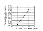
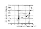
- the total length M of the inclusions in the rolling direction and the crack propagation resistance value T.I. M.M It is a figure which shows the relationship. It is a figure which shows the relationship between S content, Ti content, REM content, and Ca content, and the sum total M of the rolling direction length of an inclusion. It is a figure which shows the relationship between the cumulative reduction rate in a primary rough rolling process, and the sum total M of the rolling direction length of an inclusion. It is a figure which shows the relationship between the cumulative reduction rate in a primary rough rolling process, and the average value of the maximum value of the major axis / minor axis ratio of inclusions.
- the tensile properties were obtained from a tensile test under the following conditions.
- a test piece was manufactured from the portion where the plate width of the test steel plate was 1 ⁇ 2 so that the tensile direction was parallel to the plate width direction of the test steel plate.
- a tensile test was performed using this test piece.
- the tensile strength (TS: Tensile Strength) and the yield point (YP: Yield Point) were calculated
- TS Tensile Strength
- YP Yield Point
- n value (work hardening index) was calculated
- the range of strain when determining the n value was nominal strain and was in the range of 3% to 12%.
- the hole expansion property was evaluated from a hole expansion test under the following conditions. Twenty test pieces each having a length in the rolling direction of 150 mm and a length in the width direction of 150 mm were manufactured from a portion where the plate width of the test steel plate was 1 ⁇ 2. Using these test pieces, a hole expansion test was performed under the following conditions. The evaluation of the hole expansion property is based on the average value ⁇ ave (unit:%) of the hole expansion rate obtained by arithmetically averaging the test results of 20 times, and the standard deviation ⁇ (unit:%) calculated from the following equation 1. went. In addition, ⁇ i in the following formula 1 represents the i-th hole expansion rate in a total of 20 tests.
- the fatigue characteristics were evaluated from fatigue tests under the following conditions.
- a test piece having the dimensions shown in FIG. 1 was produced from the hot-rolled test steel sheet.
- 11 is a specimen for fatigue testing
- RD Rolling Direction
- TD Transverse Direction
- a plane bending repeated stress was applied to the constricted portion at the center of the test piece, and the plane bending fatigue life, which was the number of repetitions until the test piece was fatigued, was measured.
- the condition of the repeated stress applied to the test piece in the fatigue test is complete swinging.
- the fracture characteristics are the crack initiation resistance value Jc (unit: J / m 2 ) and the crack propagation resistance value T.C. M.M. Evaluation was made based on (unit: J / m 3 ), fracture surface transition temperature vTrs (unit: ° C.) and Charpy absorbed energy E (unit: J) obtained by the Charpy impact test.
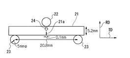
- FIG. 2A is an explanatory diagram of a three-point bending test with a notch.
- 21 is a test piece for a three-point bending test with a notch
- 21a is a notch
- 22 is a load point
- 23 is a support point
- 24 is a displacement direction.
- 2B is a cross-sectional view including a notched test piece 21 before the notched three-point bending test, including a notch 21a in which the sheet width direction TD of the test steel plate is a normal line.
- ND Normal Direction
- the thickness direction As shown in these figures, the longitudinal direction of the test piece 21 is 20.8 mm, the thickness of the displacement direction 24 of the test piece 21 is 5.2 mm, the depth of the notch 21a in the displacement direction 24 is 2.6 mm, and the ligament The thickness C in the displacement direction 24 (a value obtained by subtracting the depth in the displacement direction 24 of the notch 21a from the thickness in the displacement direction 24 of the test piece 21) is 2.6 mm, and the thickness B of the test steel sheet is 2. 9 mm.
- FIG. 2C illustrates a fracture surface including a notch of the notched specimen 21 that has been forcibly broken after the notched three-point bending test.
- this fracture surface as a result of the oxidation coloring, a fracture surface caused by a notched three-point bending test and a fracture surface caused by forced fracture can be clearly distinguished.
- 21b is a fracture surface caused by a notched three-point bending test
- 21c is a fracture surface caused by forced fracture
- L1 is the depth of the fracture surface 21b at the position where the thickness of the test steel sheet is 1/4.
- L2 represents the depth of the fracture surface 21b when the plate thickness of the test steel plate is 1/2
- L3 represents the depth of the fracture surface 21b when the plate thickness of the test steel plate is 3/4.
- the fracture surface 21b was observed, L1, L2, and L3 were measured, and the crack propagation amount ⁇ a (unit: m) was obtained from the following Equation 3.
- ⁇ a (L1 + L2 + L3) / 3 (Formula 3)
- FIG. 3A illustrates a load displacement curve obtained by a notched three-point bending test.
- a processing energy A unit: J
- the processing energy per 1 m 2 from the following formula 4.
- J unit: J / m 2
- J (2 ⁇ A) / (B ⁇ C) (Formula 4)
- FIG. 3B is a graph showing the relationship between the crack propagation amount ⁇ a and the processing energy J per m 2 when the stroke condition is variously changed in the three-point bending test with notch.
- the intersection of a linear regression line with respect to ⁇ a and J and a straight line passing through the origin and having an inclination of 3 ⁇ (YP + TS) / 2 was obtained.
- the value of the processing energy J per 1 m 2 at this intersection was defined as the crack initiation resistance value Jc (unit: J / m 2 ), which is a value representing the crack initiation resistance of the test steel sheet.
- the slope of the linear regression line is expressed by the crack propagation resistance value T.sub.D representing the crack propagation resistance of the test steel sheet.
- M.M. (Unit: J / m 3 ).
- the crack generation resistance value Jc is an index value indicating the degree of processing energy required for generating a crack. That is, this crack initiation resistance value Jc represents the resistance against the occurrence of cracks (start of destruction) from the steel sheet constituting the structural member when an impact load is applied.
- the crack propagation resistance value T.I. M.M. Is an index value indicating the degree of processing energy required to extend the crack. That is, the crack propagation resistance value T.I. M.M. Represents resistance against large-scale destruction (development of destruction) of the steel sheet constituting the structural member.
- the conditions for the Charpy impact test are as follows.
- a V-notch test piece was manufactured so that the longitudinal direction of the test piece was parallel to the plate width direction of the test steel plate.
- the test piece size is 55 mm in length in the longitudinal direction of the test piece, 10 mm in thickness in the direction in which the impact of the test piece is applied, 2.5 mm in thickness in the direction perpendicular to the longitudinal direction and the impact direction of the test piece,
- the V notch has a depth of 2 mm and an angle of 45 °.
- a Charpy impact test was performed to determine the fracture surface transition temperature vTrs (unit: ° C.) and Charpy absorbed energy E (unit: J).
- the fracture surface transition temperature vTrs was a temperature at which the ductile fracture surface ratio was 50%
- the Charpy absorbed energy E was a value obtained when the test temperature was room temperature (23 ° C. ⁇ 5 ° C.).
- the fracture characteristics of the steel sheet were also evaluated based on these fracture surface transition temperatures vTrs and Charpy absorbed energy E.
- the hot-rolled steel sheet according to the present embodiment has, as the above-described characteristic values, a tensile strength TS of 590 MPa or more, a hole expansion rate average value ⁇ ave of 60% or more, a hole expansion rate standard deviation ⁇ of 15% or less, and plane bending.
- Fatigue life is 400,000 times or more
- crack initiation resistance value Jc is 0.5 MJ / m 2 or more
- the fracture surface transition temperature vTrs is ⁇ 13 ° C. or less
- the Charpy absorbed energy E is 16 J or more.
- the chemical composition of the steel sheet is EPMA (Electron Probe Micro-Analyzer: Electron Probe X-ray microanalysis), AAS (Atomic Absorption Spectrometry: Atomic Absorption Spectroscopy) Analysis) or ICP-MS (Inductively Coupled Plasma-Mass Spectrometry).
- EPMA Electron Probe Micro-Analyzer: Electron Probe X-ray microanalysis
- AAS Automatic Absorption Spectrometry: Atomic Absorption Spectroscopy
- ICP-MS Inductively Coupled Plasma-Mass Spectrometry
- the observation of the metal structure of the steel sheet was performed by the following method.
- a sample for observing the metal structure was cut out from a portion where the plate width of the steel plate was 1/4 so that a cross section having the normal direction in the plate width direction (hereinafter referred to as L cross section) was an observation surface.
- L cross section a cross section having the normal direction in the plate width direction
- this sample was mirror-polished.
- the inclusions contained in the metal structure were observed with an optical microscope at a magnification of 400 times with the vicinity of the center of the plate thickness in the L section as an observation position.
- the sample after mirror polishing was subjected to nital corrosion or repeller corrosion, and metal phases such as ferrite, martensite, retained austenite, bainite, and pearlite were observed.
- the average crystal grain size of ferrite was determined as follows. With the central portion of the plate thickness in the L section as the observation position, the crystal orientation distribution of the portion having the plate thickness direction of 500 ⁇ m and the rolling direction of 500 ⁇ m was measured by an EBSD (Electron Back-Scattered Diffraction Pattern) method in 1 ⁇ m steps. . Then, a point having an orientation difference of 15 ° or more is connected to form a high-angle grain boundary, and an arithmetic average value of the equivalent circle diameter of each crystal grain surrounded by the high-angle grain boundary is obtained to obtain an average crystal grain size of ferrite. It was.
- EBSD Electro Back-Scattered Diffraction Pattern
- a crystal grain having an IQ (Image Quality) value of 100 or more is regarded as ferrite, and a crystal grain having an IQ value of 100 or less is regarded as a metal phase other than ferrite. It was.
- the area fractions of ferrite, martensite, retained austenite, bainite, pearlite, and the like were determined by image analysis of metal structure photographs.
- the presence of inclusions causes voids to be formed in the steel when the steel sheet is deformed and promotes ductile fracture, thus deteriorating the hole expandability. Furthermore, the stress concentration in the vicinity of the inclusion increases during plastic deformation of the steel sheet as the shape of the inclusion is elongated in the rolling direction of the steel sheet. That is, the hole expansibility is greatly influenced by the shape of the inclusions in addition to the presence of the inclusions. Conventionally, it has been known that as the length in the rolling direction of a single inclusion is larger, the hole expandability is greatly deteriorated.
- the present inventor when a plurality of inclusions such as drawn inclusions and spherical inclusions are distributed at a predetermined interval in the rolling direction of the steel sheet, which is a crack propagation direction, to form an aggregate It has been found that the hole expandability is deteriorated in the same manner as the inclusions. This is presumably because a large stress concentration is generated in the vicinity of the aggregate due to a synergistic effect of strain introduced in the vicinity of each inclusion constituting the aggregate when the steel plate is deformed. Quantitatively, an aggregate of inclusions having a major axis of 3 ⁇ m or more that are arranged at an interval of 50 ⁇ m or less with respect to other adjacent inclusions on a straight line in the rolling direction of the steel sheet is stretched alone.
- an aggregate of inclusions in which the interval in the rolling direction between inclusions is 50 ⁇ m or less and each major axis is 3 ⁇ m or more is referred to as an inclusion group.
- an inclusion which exists alone with an interval in the rolling direction between inclusions exceeding 50 ⁇ m is referred to as an independent inclusion.
- the above-mentioned major axis means the longest diameter in the cross-sectional shape of the observed inclusion, and in many cases is the diameter in the rolling direction.
- FIG. 4A is a schematic diagram of an inclusion group that is an aggregate of inclusions.
- 41a to 41e are inclusions each having a major axis of 3 ⁇ m or more
- F is an interval between inclusions in the rolling direction
- G is an inclusion group
- GL is a length of the inclusion group in the rolling direction.
- an aggregate of inclusions having an interval F of 50 ⁇ m or less along the rolling direction RD of the steel sheet, specifically, the inclusion 41b, the inclusion 41c, and the inclusion 41d are combined into one set.
- the inclusion group G is regarded as a body.
- the length GL in the rolling direction of the inclusion group G is measured.
- Inclusion group G having a length GL of 30 ⁇ m or more affects the hole expandability of the steel sheet.
- Inclusion group G having a length GL in the rolling direction of less than 30 ⁇ m has a small effect on hole expansibility.
- inclusions having a major axis of less than 3 ⁇ m are not included in the structure of the inclusion group G because the influence on the hole expandability is small even if the interval F is 50 ⁇ m or less.
- the inclusion 41a and the inclusion 41e are independent inclusions.
- FIG. 4B is a schematic diagram of independent inclusions.
- reference numerals 41f to 41h denote inclusions each having a major axis of 3 ⁇ m or more
- H denotes independent inclusions
- HL denotes the length of the independent inclusions in the rolling direction.
- inclusions with an interval F exceeding 50 ⁇ m specifically, inclusions 41f, inclusions 41g, and inclusions 41h are independent inclusions H, respectively.
- the length HL in the rolling direction of these independent inclusions H is measured.
- the independent inclusion H having a length HL of 30 ⁇ m or more affects the hole expandability of the steel plate.
- the independent inclusion H having a length HL in the rolling direction of less than 30 ⁇ m has a small effect on the hole expandability.
- FIG. 4C is a schematic diagram of inclusion group G including inclusions whose rolling direction length is 30 ⁇ m or more.
- reference numerals 41i to 41l denote inclusions each having a major axis of 3 ⁇ m or more.
- the inclusion 41j has a length (major axis) in the rolling direction of 30 ⁇ m or more.
- inclusions 41j and inclusions 41k which are inclusions having an interval F of 50 ⁇ m or less along the rolling direction RD of the steel sheet, form inclusion group G that is one aggregate, and inclusions 41i and inclusions.
- the object 41l becomes an independent inclusion H.
- the inclusion 41j and the inclusion 41k having a distance F of 50 ⁇ m or less exist, so that the inclusion 41j is a part of the inclusion group G. did.
- the independent inclusion H that is not included in the inclusion group G and has a rolling direction length HL of 30 ⁇ m or more is referred to as a stretched inclusion.
- the reason for determining the sum M which is a value obtained by converting the sum I per 1 mm 2 area, not the average value of the sum I of the lengths in the rolling direction of the inclusions, is as follows.
- the above-mentioned total M has an influence on the fracture characteristics of the steel sheet in addition to the hole expanding property of the steel sheet.
- Charpy absorbed energy E which is energy required for fracture of the test piece in the temperature range where ductile fracture occurs, is a crack initiation resistance value Jc and a crack propagation resistance value T.sub. M.M. It is an index that both influence. Similarly, when the value of the total sum M is large, the Charpy absorbed energy E also decreases.
- the above sum M also affects the fatigue characteristics of the steel sheet. It has been found that the fatigue life tends to decrease as the value of the sum M increases. It is considered that as the value of the total sum M increases, the number of inclusion groups G and stretched inclusions that become the starting point of fatigue failure increases, resulting in a decrease in fatigue life.
- the total length M in the rolling direction of the inclusions described above was measured, and based on this, the average value ⁇ ave of the hole expansion ratio, the crack initiation resistance value Jc, the crack propagation resistance value T.sub. M.M. , Charpy absorbed energy E, fatigue life, etc. were evaluated.
- the major axis / minor axis ratio of inclusions represented by the major axis of inclusions / the minor axis of inclusions was measured.
- the major axis / minor axis ratio was measured for all the inclusions in one observation field, and the maximum value was determined. This measurement was performed 30 times with different fields of view. And the value which averaged the maximum value of each major axis / minor axis ratio calculated
- the major axis / minor axis ratio of the inclusions was determined because the shape of each inclusion was round and the maximum value of the major axis / minor axis ratio, even when the total sum M in the rolling direction of the inclusions was the same value.
- the average value is small, the stress concentration in the vicinity of the inclusions is reduced when the steel sheet is deformed, and the average value ⁇ ave of the hole expansion rate, the crack generation resistance value Jc, and the Charpy absorbed energy E are further improved. is there.
- the texture of the steel plate was measured.
- the texture was measured by X-ray diffraction measurement.
- X-ray diffraction measurement was performed using a diffractometer method using an appropriate X-ray tube.
- a test piece having a length of 20 mm in the plate width direction and a length of 20 mm in the rolling direction was cut out from a portion where the plate width of the steel plate was 1 ⁇ 2. This test piece was polished by mechanical polishing so that the position of 1/2 of the plate thickness of the steel plate became the measurement surface, and then strain was removed by electrolytic polishing or the like.
- a numerical value obtained by measuring the X-ray diffraction measurement sample and a standard sample having no accumulation in a specific orientation by the X-ray diffraction method under the same conditions, and dividing the X-ray intensity of the steel plate by the X-ray intensity of the standard sample. was the X-ray random intensity ratio.
- the X-ray random intensity ratio is synonymous with the extreme density.
- the texture may be measured using an EBSD method or an ECP (Electron Channeling Pattern) method.
- the X-ray random intensity ratio of the ⁇ 211 ⁇ plane (the pole density of the ⁇ 211 ⁇ plane or the same meaning as the ⁇ 211 ⁇ plane strength) was measured as the texture of the steel sheet.
- the characteristics of the hot-rolled steel sheet according to this embodiment are, for example, that the average value ⁇ ave of the hole expansion rate is 60% or more, the standard deviation ⁇ of the hole expansion rate is 15% or less, and the crack propagation resistance value T.E. M.M. Will be described in terms of the numerical limit range and the reason for the above-mentioned total sum M and the average value of the major axis / minor axis ratio to satisfy 600 MJ / m 3 or more.
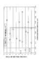
- FIG. 5 is a graph showing the relationship between the total length M of inclusions in the rolling direction, the average value of the maximum length / short diameter ratio of inclusions, and the average value ⁇ ave of the hole expansion ratio.
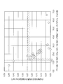
- FIG. 6 is a diagram showing the relationship between the total length M of inclusions in the rolling direction, the average value of the maximum length / short diameter ratio of inclusions, and the standard deviation ⁇ of the hole expansion ratio.
- the average value ⁇ ave of the hole expansion ratio of the steel sheet becomes smaller as the value of the sum M of the lengths in the rolling direction of the inclusion is smaller and as the average value of the maximum value of the major axis / minor axis ratio is smaller. It turns out that it improves. Further, as shown in FIG. 6, it can be seen that the standard deviation ⁇ of the hole expansion ratio is improved as the average value of the maximum value of the major axis / minor axis ratio of the inclusion is smaller.
- 6 represents the hot rolling according to this embodiment except for the configuration related to the sum M of the lengths in the rolling direction of the inclusions and the average value of the maximum value of the major axis / minor axis ratio. It shows what satisfies the structure of the steel sheet.
- the total length M in the rolling direction of the inclusions is 0 mm / mm 2 or more and 0.25 mm / mm 2 or less, and the average of the maximum values of the major axis / minor axis ratio is 1.0 or more and 8.
- the average value ⁇ ave of the hole expansion ratio can be 60% or more and the standard deviation ⁇ can be 15% or less. The reason for this is that, as described above, the value of the sum M and the average value of the major axis / minor axis ratio are reduced, so that stress concentration near the inclusions during plastic deformation of the steel sheet is alleviated. It is believed that there is.
- the total length M of inclusions in the rolling direction is set to 0 mm / mm 2 or more and 0.20 mm / mm 2 or less, more preferably the total length M of inclusions in the rolling direction length is set to 0 mm / mm 2 or more. 15 mm / mm 2 or less.
- the average value of the maximum value of the major axis / minor axis ratio is 1.0 or more and 3.0 or less, so that the average value ⁇ ave of the hole expansion ratio is 65% or more and the standard deviation ⁇ is 10% or less. You can see that you can. More preferably, the average of the maximum values of the major axis / minor axis ratio is 1.0 or more and 2.0 or less.
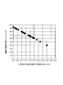
- FIG. 7 shows the total length M of inclusions in the rolling direction and the crack propagation resistance value T.I. M.M. It is a figure which shows the relationship. From this figure, when the total length M in the rolling direction of inclusions is 0 mm / mm 2 or more and 0.25 mm / mm 2 or less, in addition to the above average value ⁇ ave and standard deviation ⁇ of the hole expansion rate, cracks Propagation resistance value M.M. It can also be seen that 600 MJ / m 3 or more is satisfied. In general, in order to prevent the destruction of the steel plate constituting the structural member, the crack propagation resistance value T.I. M.M. It is important to improve. As described above, the crack propagation resistance value T.I. M.M. Has a tendency to depend on the total length M of the inclusions in the rolling direction, and it has been found that it is important to control the total number M within the above range.
- the influence is not as great as the above MnS precipitate and the residue of the desulfurization material, it is CaS that precipitates without using REM (Rare Earth Metal) oxide or sulfide as a nucleus, or calcium that is a mixture of CaO and alumina. It has been found that precipitates such as aluminate may increase the above-mentioned total value M and the above average value of the major axis / minor axis ratio. These precipitates such as CaS and calcium aluminate may be formed into a shape stretched in the rolling direction by rolling, so that there is a possibility of deteriorating the hole expanding property and fracture characteristics of the steel plate.
- the upper limit value is set to 0.01% in mass% in order to reduce the total S content in the steel.
- FIG. 8 is a diagram illustrating the relationship between the S content, the Ti content, the REM content, and the Ca content, and the total length M of inclusions in the rolling direction.
- the value of (Ti / 48) / (S / 32) + ⁇ (Ca / 40) / (S / 32) + (REM / 140) / (S / 32) ⁇ ⁇ 15 should be 12.0 or more and 150 or less.
- the total sum M is 0 mm / mm 2 or more and 0.25 mm / mm 2 or less. That is, in the hot-rolled steel sheet according to the present embodiment, the content expressed by mass% of each element in the chemical component needs to satisfy the following formula 6. It is considered that the formation of stretched MnS precipitates is suppressed by satisfying this formula 6. Although not shown, it was found that the average value of the maximum value of the major axis / minor axis ratio of inclusions is 1.0 or more and 8.0 or less when the following Expression 6 is satisfied.
- the total M is 0 mm / mm 2 or more and 0.25 mm / mm 2 or less, and the average of the maximum value of the major axis / minor axis ratio of the inclusion is 1.0 or more and 8.0 or less. did. 12.0 ⁇ (Ti / 48) / (S / 32) + ⁇ (Ca / 40) / (S / 32) + (REM / 140) / (S / 32) ⁇ ⁇ 15 ⁇ 150 (formula 6)
- the above formula 6 is satisfied.
- the cumulative rolling reduction is set to 10% or more and 70% or less in a temperature range of over 1150 ° C. and 1400 ° C. or less.
- the content expressed by mass% of each element in the chemical component should satisfy the following formula 7.
- the average of the maximum value of the major axis / minor axis ratio of inclusions is preferably 1.0 or more and 3.0 or less.
- the cumulative rolling reduction is 10% or more and 65% or less in a temperature range of more than 1150 ° C. and 1400 ° C. or less.
- the numerical limit range and the reason for the limitation will be described.
- the described% is mass%.
- C 0.03% to 0.1%
- C (carbon) is an element contributing to the improvement of the tensile strength TS.
- the C content is small, the fracture surface transition temperature vTrs increases due to the coarsening of the metal structure. Moreover, when there is little C content, it will become difficult to obtain the martensite and retained austenite of the target area fraction.
- C content shall be 0.03% or more and 0.1% or less.
- the content is 0.04% or more and 0.08% or less. More preferably, it is 0.04% or more and 0.07% or less.
- Mn 0.5% to 3.0%
- Mn manganese
- Mn is an element that contributes to improving the tensile strength TS of the steel sheet as a solid solution strengthening element.
- the Mn content is 0.5% or more.
- Mn content shall be 0.5% or more and 3.0% or less. If the Mn content is more than 3.0%, ferrite transformation is suppressed and the area fraction of martensite and retained austenite increases.
- the Mn content is set to 0.8% or more and 2.0% or less. More preferably, it is 1.0% or more and 1.5% or less.
- At least one of Si (silicon) and Al (aluminum) is contained.
- at least 1 of Si and Al is contained and content of Si + Al shall be 0.5% or more.
- the average value ⁇ ave of the hole expansion rate is lowered.
- it is 1.5% or more and 3.0% or less. More preferably, it is 1.8% or more and 2.6% or less.
- Si 0.5% to 2.0%
- Si is an element that contributes to improving the tensile strength TS of steel and promoting ferrite transformation.
- the Si content is preferably 0.5% or more.
- Si content shall be 0.5% or more and 2.0% or less.
- Al 0.005% to 2.0%
- Al is an element necessary for deoxidation of molten steel, and is an element that contributes to an improvement in tensile strength TS.
- the Al content is preferably 0.005% or more.
- Al content shall be 0.005% or more and 2.0% or less.
- the hot-rolled steel sheet according to this embodiment further contains at least one selected from Ti, REM, and Ca with the following content.
- Ti 0.001% to 0.3%
- Ti titanium
- Ti is an element that contributes to the improvement of the tensile strength TS of the steel sheet by being finely precipitated as TiC.
- Ti is an element that suppresses precipitation of MnS that is stretched during rolling by precipitating as TiS. Therefore, the sum M of the lengths in the rolling direction of inclusions and the average value of the maximum value of the major axis / minor axis ratio of the inclusions are reduced.
- Ti content shall be 0.001% or more. However, if the Ti content exceeds 0.3%, the strength becomes excessively high, and the average value ⁇ ave of the hole expansion rate, crack initiation resistance value Jc, and Charpy absorbed energy E are reduced.
- Ti content shall be 0.001% or more and 0.3% or less.
- the content is 0.01% or more and 0.3% or less. More preferably, it is 0.05% or more and 0.18% or less. Most preferably, it is 0.08% or more and 0.15% or less.
- REM 0.0001% to 0.02% REM (Rare Earth Metal) is an element that suppresses the formation of MnS by bonding with S in steel. Moreover, it is an element which reduces the average value of the maximum value of the major axis / minor axis ratio of inclusions and the total sum M of the length in the rolling direction by making the form of sulfide such as MnS spherical. If the REM content is less than 0.0001%, the effect of suppressing the generation of MnS and the effect of spheroidizing the form of sulfide such as MnS cannot be obtained sufficiently.
- REM content shall be 0.0001% or more and 0.02% or less.
- the content is 0.0005% or more and 0.005% or less. More preferably, it is 0.001% or more and 0.004% or less.
- REM is a generic name for a total of 17 elements including 15 elements from lanthanum having an atomic number of 57 to lutesium having an atomic number of 57 plus scandium having an atomic number of 21 and yttrium having an atomic number of 39.
- misch metal which is a mixture of these elements, and added to the steel.
- Ca 0.0001% to 0.01%
- Ca (calcium) is an element that suppresses the generation of MnS by binding to S in steel. Moreover, it is an element which reduces the average value of the maximum value of the major axis / minor axis ratio of inclusions and the total sum M of the length in the rolling direction by making the form of sulfide such as MnS spherical.
- the Ca content is less than 0.0001%, the effect of suppressing the generation of MnS and the effect of spheroidizing the form of sulfide such as MnS cannot be obtained sufficiently.
- Ca content shall be 0.0001% or more and 0.01% or less.
- the content is 0.0001% or more and 0.005% or less. More preferably, it is 0.001% or more and 0.003% or less. More preferably, it is 0.0015% or more and 0.0025% or less.
- the hot-rolled steel sheet according to the present embodiment contains at least one selected from the above-described Ti, REM, and Ca, and at the same time, the content expressed by mass% of each element in the chemical component is expressed by the following formula 8. Satisfied.
- the impurity S will be described in detail later.
- the amount of precipitation of MnS precipitates in the steel is reduced, the average value of the maximum value of the major axis / minor axis ratio of inclusions, and the sum M of the rolling direction lengths of inclusions, Is obtained.
- the total length M of inclusions in the rolling direction becomes 0 mm / mm 2 or more and 0.25 mm / mm 2 or less, and the average value of the maximum value of the major axis / minor axis ratio of the inclusions is 1.0 or more and 8.0. It becomes as follows. As a result, the average value ⁇ ave, standard deviation ⁇ , crack initiation resistance value Jc, crack propagation resistance value T.V. M.M. The effect of improving Charpy absorbed energy E and fatigue life can be obtained. There exists a possibility that the said effect may not be acquired as the value of the following formula 8 is less than 12.0. Preferably, it is 30.0 or more.
- the tensile strength TS of a steel plate will improve.
- the tensile strength TS of the steel sheet can be 780 MPa or more and 980 MPa or less, and at this time, the plane bending fatigue life is 500,000 times or more. . This is due to TiC precipitation strengthening.
- Ti is not added or the content is low within the above range, the formability and fracture characteristics of the steel sheet are improved.
- the tensile strength TS of the steel sheet is 590 MPa or more and less than 780 MPa, but the average value ⁇ ave of the hole expansion rate is 90% or more.
- the crack initiation resistance value Jc can be 0.9 MJ / m 2 or more, and the Charpy absorbed energy E can be 35 J or more. This is because the amount of TiC deposited is reduced.
- the content of Ti is set to Ti: 0.001.
- the content is 001% to less than 0.08%.
- the content of Ti is set to Ti: 0.01 % To less than 0.08%.
- the average value of the maximum value of the major axis / minor axis ratio of inclusions is preferably 1.0 or more and 3.0 or less. That is, the content expressed by mass% of each element in the chemical component satisfies the following formula 9, and the value obtained by averaging the maximum value of the major axis / minor axis ratio of inclusions is 1.0 or more and 3. It is preferably 0 or less. More preferably, it is 1.0 or more and 2.0 or less.
- the hot-rolled steel sheet according to this embodiment contains inevitable impurities in addition to the basic components described above.
- the inevitable impurities mean auxiliary materials such as scrap and elements such as P, S, N, O, Pb, Cd, Zn, As, and Sb that are inevitably mixed in from the manufacturing process.
- P, S, and N are limited as follows in order to preferably exhibit the above effects.
- the limit range of these impurity contents includes 0%, it is difficult to achieve 0% stably industrially.
- the described% is mass%.
- P 0.1% or less
- P (phosphorus) is an inevitably mixed impurity. If the P content exceeds 0.1%, the amount of P segregation at the grain boundaries increases, and the average value ⁇ ave of the hole expansion rate, crack initiation resistance value Jc, and Charpy absorbed energy E are deteriorated. For this reason, the P content is limited to 0.1% or less. Since it is desirable that the P content is small, 0% is included in the above limit range. However, it is not technically easy to make the P content 0%, and even if it is stably made less than 0.0001%, the steelmaking cost becomes high. Therefore, the P content limit range is preferably 0.0001% or more and 0.1% or less. More preferably, it is 0.001% or more and 0.03% or less.
- S 0.01% or less S (sulfur) is an impurity inevitably mixed. If the S content exceeds 0.01%, a large amount of MnS is generated in the steel when the steel slab is heated, and this is stretched by hot rolling. Therefore, the total value M of the inclusions in the rolling direction and the average value of the maximum value of the major axis / minor axis ratio of the inclusions are increased, and the average value ⁇ ave of the target hole expansion ratio, standard deviation ⁇ , crack initiation resistance Value Jc, crack propagation resistance value T.I. M.M. Characteristics such as Charpy absorbed energy E and fatigue life cannot be obtained. For this reason, the S content is limited to 0.01% or less. The smaller the S content, the better.
- the limit range of the S content is preferably 0.0001% or more and 0.01% or less. Further, when desulfurization using a desulfurization material is not performed during secondary refining, it is difficult to make the S content less than 0.003%. In this case, the S content is preferably 0.003% to 0.01%.
- N nitrogen
- nitrogen is an unavoidable impurity. If the N content exceeds 0.02%, precipitates are formed with Ti and Nb, and the amount of TiC precipitated is reduced. As a result, the tensile strength TS of the steel sheet decreases. For this reason, the N content is limited to 0.02% or less. The smaller the N content, the better. Therefore, 0% is included in the above limit range. However, it is not technically easy to make the N content 0%, and even if it is stably made less than 0.0001%, the steelmaking cost becomes high. Therefore, the N content limit range is preferably 0.0001% or more and 0.02% or less. Moreover, in order to suppress the fall of tensile strength TS more effectively, it is preferable to make content of N 0.005% or less.
- the hot-rolled steel sheet according to this embodiment further contains at least one of Nb, B, Cu, Cr, Mo, Ni, and V as a selection component in addition to the basic component and the impurity element described above. Also good.
- Nb, B, Cu, Cr, Mo, Ni, and V as a selection component in addition to the basic component and the impurity element described above. Also good.
- the numerical limitation range of the selected component and the reason for limitation will be described.
- the described% is mass%.
- Nb 0.001% to 0.1%
- Nb niobium
- the Nb content is preferably 0.001% or more.
- the temperature range at which dynamic recrystallization occurs during hot rolling may be narrowed. Therefore, a large number of unrecrystallized rolled textures that increase the X-ray random intensity ratio of the ⁇ 211 ⁇ plane remain after hot rolling. The texture will be described later in detail.
- Nb content shall be 0.001% or more and 0.1% or less. More preferably, it is 0.002% or more and 0.07% or less. Most preferably, it is 0.002% or more and less than 0.02%. If the Nb content is 0% to 0.1%, each characteristic value of the hot-rolled steel sheet is not adversely affected.
- B 0.0001% to 0.0040%
- B is an element that contributes to the improvement of the tensile strength TS of steel through grain refinement.
- the B content is preferably 0.0001% or more.
- the temperature range at which dynamic recrystallization occurs during hot rolling may be narrowed. Therefore, a large number of unrecrystallized rolled textures that increase the X-ray random intensity ratio of the ⁇ 211 ⁇ plane remain after hot rolling.
- the B content is preferably 0.0001% or more and 0.0040% or less. More preferably, it is 0.0001% or more and 0.0020% or less. Most preferably, it is 0.0005% or more and 0.0015% or less. If the B content is 0% to 0.0040%, each characteristic value of the hot-rolled steel sheet is not adversely affected.
- Cu 0.001% to 1.0%
- Cu is an element having an effect of improving the tensile strength TS of the hot-rolled steel sheet by precipitation strengthening or solid solution strengthening.
- this effect cannot be obtained when the Cu content is less than 0.001%.
- the Cu content if the Cu content is more than 1.0%, the strength becomes excessively high and the average value ⁇ ave of the hole expansion rate may be lowered.
- Cr 0.001% to 1.0%
- Cr is an element having an effect of improving the tensile strength TS of the hot-rolled steel sheet by precipitation strengthening or solid solution strengthening.
- this effect cannot be obtained when the Cr content is less than 0.001%.
- the Cr content if the Cr content is more than 1.0%, the strength becomes excessively high and the average value ⁇ ave of the hole expansion rate may be lowered.
- Mo 0.001% to 1.0%
- Mo is an element having an effect of improving the tensile strength TS of the hot-rolled steel sheet by precipitation strengthening or solid solution strengthening.
- this effect cannot be obtained when the Mo content is less than 0.001%.
- Mo content shall be 0.001% or more and 1.0% or less. More preferably, it is 0.001% or more and 0.03% or less. More preferably, it is 0.02% or more and 0.2% or less. If the Mo content is 0% to 1.0%, each characteristic value of the hot-rolled steel sheet is not adversely affected.
- Ni 0.001% to 1.0%
- Ni is an element having an effect of improving the tensile strength TS of the hot-rolled steel sheet by precipitation strengthening or solid solution strengthening.
- this effect cannot be obtained when the Ni content is less than 0.001%.
- Ni content if the Ni content is more than 1.0%, the strength becomes excessively high and there is a possibility that the average value ⁇ ave of the hole expansion rate is lowered. For this reason, it is preferable that Ni content shall be 0.001% or more and 1.0% or less. More preferably, it is 0.05% or more and 0.2% or less. If the Ni content is 0% to 1.0%, each characteristic value of the hot rolled steel sheet will not be adversely affected.
- V 0.001% to 0.2%
- V content shall be 0.001% or more and 0.2% or less. More preferably, it is 0.005% or more and 0.2% or less. More preferably, it is 0.01% or more and 0.2% or less. Most preferably, it is 0.01% or more and 0.15% or less. If the V content is 0% to 0.2%, there is no adverse effect on the respective characteristic values of the hot-rolled steel sheet.
- the hot-rolled steel sheet according to the present embodiment may contain Zr, Sn, Co, W, and Mg in total from 0% to 1% as necessary.
- the metallographic structure of the hot-rolled steel sheet according to the present embodiment includes ferrite as a main phase, at least one of martensite and retained austenite as a second phase, and a plurality of inclusions.
- tissue By setting it as such a mixed structure
- tissue it becomes possible to aim at coexistence with high tensile strength TS and elongation (n value).
- TS tensile strength
- elongation n value
- the reason is considered to be that ductility is ensured by the ferrite which is a relatively soft main phase, and the tensile strength TS is obtained by the hard second phase.
- a favorable fatigue characteristic is acquired by setting it as the said mixed structure. This is presumably because the growth of fatigue cracks is slowed by martensite and retained austenite, which are relatively hard second phases.
- the metal structure of the hot-rolled steel sheet according to the present embodiment has an area fraction of the main phase of 90% to 99%, and the martensite and residual austenite as the second phase.
- the total area fraction is 1% or more and 10% or less.
- the area fraction of the main phase is less than 90%, the metal structure does not become a target mixed structure, and thus the above effect cannot be obtained.
- the total area fraction of the second phase is more than 10%, ductile fracture is promoted, and the average value ⁇ ave of the hole expansion value, crack initiation resistance value Jc, and Charpy absorbed energy E are deteriorated.
- the area fraction of the second phase is less than 1% in total, the metal structure does not become the target mixed structure, and thus the above effect cannot be obtained.
- the area fraction of the main phase is 95% or more and 99% or less, and the area fraction of martensite and residual austenite as the second phase is 1% or more and 5% or less in total. To do.
- the metal structure contains a small amount of bainite, pearlite, cementite, etc. in addition to the main phase ferrite, the second phase martensite or retained austenite, and a plurality of inclusions.
- the area fraction of bainite and pearlite is preferably 0% or more and less than 5.0% in total. As a result, the metal structure becomes the desired mixed structure, and the above effect is obtained, which is preferable.
- the ferrite which is the main phase, has an average crystal grain size of 2 ⁇ m or more and 10 ⁇ m or less. This is because the target fracture surface transition temperature vTrs can be obtained when the average crystal grain size of ferrite as the main phase is 10 ⁇ m or less. Moreover, in order to make the average crystal grain size of ferrite as the main phase less than 2 ⁇ m, it is necessary to select strict manufacturing conditions, and the load on the manufacturing equipment is large. For this reason, the average crystal grain size of the main phase ferrite is set to 2 ⁇ m or more and 10 ⁇ m or less. Preferably, it is 2 ⁇ m or more and 7 ⁇ m or less. More preferably, it is 2 ⁇ m or more and 6 ⁇ m or less.
- the martensite and the retained austenite as the second phase have an average crystal grain size of 0.5 ⁇ m or more and 8.0 ⁇ m or less.
- the average crystal grain size of the second phase is more than 8.0 ⁇ m, the stress concentration generated in the vicinity of the second phase is increased, and there is a possibility that characteristics such as the average value ⁇ ave of the hole expansion rate are deteriorated.
- the average crystal grain size of the second phase is set to 0.5 ⁇ m or more and 8.0 ⁇ m or less.
- the inclusions included in the metal structure are the maximum of the major axis / minor axis ratio of the inclusions in each field of view when the L cross section in which the plate width direction of the steel sheet is a normal line is observed 30 times in a field of 0.0025 mm 2.
- the average value is 1.0 or more and 8.0 or less. This is because, when the average value of the major axis / minor axis ratio is more than 8.0, the stress concentration near the inclusion increases when the steel plate is deformed, and the average value ⁇ ave of the target hole expansion rate, the standard deviation This is because ⁇ , crack initiation resistance value Jc, and Charpy absorbed energy E cannot be obtained.
- the lower limit value of the average value of the major axis / minor axis ratio is not particularly limited, but it is technically difficult to make it less than 1.0.
- the average value of the major axis / minor axis ratio is 1.0 or more and 8.0 or less.
- the average value of the major axis / minor axis ratio is preferably 1.0 or more and 3.0 or less.
- the inclusions included in the metal structure are an aggregate of inclusions having an interval F in the rolling direction between inclusions of 50 ⁇ m or less and a major axis of 3 ⁇ m or more, and the interval F is 50 ⁇ m.
- the inclusion that is super is an independent inclusion H
- the inclusion group G in which the rolling direction length GL is 30 ⁇ m or more and the independent inclusion H in which the rolling direction length HL is 30 ⁇ m or more are in the rolling direction.
- the total length M is set to 0 mm or more and 0.25 mm or less per 1 mm 2 of the L cross section in which the plate width direction of the steel plate is a normal line.
- the sum M may be zero.
- the total sum M is set to 0 mm or more and 0.15 mm or less per 1 mm 2 of the L cross section in which the plate width direction of the steel plate is a normal line.
- the total number of MnS precipitates and CaS precipitates whose major axis is 3 ⁇ m or more is 0% or more in total with respect to the total number of inclusions whose major axis is 3 ⁇ m or more.
- it is less than 70%.
- the total value M and the average value of the major axis / minor axis ratio can be preferably controlled. it can. Inclusions having a major axis of less than 3 ⁇ m are not considered because they have a small effect on properties such as the average value ⁇ ave of the hole expansion rate.
- the inclusions mentioned here mainly include sulfides such as MnS and CaS in steel, oxides such as CaO—Al 2 O 3 -based compounds (calcium aluminate), and desulfurization materials such as CaF 2. This refers to the remaining material.
- the ⁇ 211 ⁇ plane X-ray random intensity ratio ( ⁇ 211 ⁇ plane strength) is 1.0 or more and 2.4 or less. If the ⁇ 211 ⁇ plane strength is greater than 2.4, the anisotropy of the steel sheet increases. And at the time of a hole expansion process, plate
- the ⁇ 211 ⁇ plane strength exceeds 2.4, the crack initiation resistance value Jc and the Charpy absorbed energy E are also deteriorated.
- the ⁇ 211 ⁇ plane strength is set to 1.0 or more and 2.4 or less.
- it is 1.0 or more and 2.0 or less.
- the X-ray random intensity ratio of the ⁇ 211 ⁇ plane, the ⁇ 211 ⁇ plane intensity, and the pole density of the ⁇ 211 ⁇ plane are synonymous.
- the X-ray random intensity ratio of the ⁇ 211 ⁇ plane is basically measured by the X-ray diffraction method, but even if measured by the EBSD method or the ECP method, no difference occurs in the measurement results. You may measure by ECP method.
- the hot-rolled steel sheet according to the present embodiment satisfies the above-described chemical component, metal structure, and texture, and thus has a tensile strength TS of 590 MPa to 980 MPa. Further, the hot rolled steel sheet according to the present embodiment satisfies the above-described chemical composition, metal structure, and texture, so that the average value ⁇ ave of the hole expansion rate is 60% or more and the standard deviation ⁇ of the hole expansion rate is 15 %, Plane bending fatigue life is 400,000 times or more, crack initiation resistance value Jc is 0.5 MJ / m 2 or more, crack propagation resistance value T.I. M.M. Is 600 MJ / m 3 or more, the fracture surface transition temperature vTrs is ⁇ 13 ° C. or less, and the Charpy absorbed energy E is 16 J or more.
- the hot-rolled steel sheet according to this embodiment preferably controls the tensile strength TS by controlling the Ti content in accordance with the purpose of use of the steel sheet.
- the Ti content is 0.001 or more and less than 0.08%
- the tensile strength TS of the steel sheet is 590 MPa or more and less than 780 MPa.
- the average value ⁇ ave of the hole expansion rate is 90% or more
- the Charpy absorbed energy E can be 35 J or more.
- the tensile strength TS of the steel sheet can be 780 MPa or more and 980 MPa or less, and among the above characteristics, the plane bending fatigue life is 500,000 times or more. Is possible.
- the REM and Ca contents may be controlled.
- the method for manufacturing a hot-rolled steel sheet according to the present embodiment includes a heating step of heating a steel slab comprising the above chemical components to 1200 ° C. or more and 1400 ° C. or less, and after this heating step, the steel slab is more than 1150 ° C. and 1400 ° C. or less.
- the primary rough rolling process in which the rolling reduction is 10% or more and 70% or less in the temperature range, and after the primary rough rolling process, the cumulative rolling reduction is 10% in the temperature range of more than 1070 ° C. and 1150 ° C. or less.
- finish rolling is performed so that the start temperature is 1000 ° C. or higher and 1070 ° C.
- Ar3 is a temperature at which ferrite transformation starts at the time of cooling.
- a steel slab made of the above chemical components obtained by continuous casting or the like is heated in a heating furnace.
- the heating temperature at this time is heated to 1200 ° C. or higher and 1400 ° C. or lower for obtaining the target tensile strength TS.
- the temperature is lower than 1200 ° C., precipitates containing Ti and Nb are not sufficiently dissolved in the steel slab and are coarsened, and the precipitation strengthening ability due to the precipitates of Ti and Nb may not be obtained. Therefore, the target tensile strength TS may not be obtained.
- the primary rough rolling step rough rolling is performed on the steel piece taken out from the heating furnace.
- rough rolling is performed in a high temperature range higher than 1150 ° C. and not higher than 1400 ° C. so that the cumulative rolling reduction is 10% or more and 70% or less. This is because if the cumulative rolling reduction in this temperature range is more than 70%, both the sum M of the lengths of inclusions in the rolling direction and the average value of the maximum value of the major axis / minor axis ratio of inclusions can be increased. Because there is sex. Therefore, the average value ⁇ ave of hole expansion ratio, standard deviation ⁇ , crack initiation resistance value Jc, crack propagation resistance value T.I. M.M.
- the lower limit value of the cumulative rolling reduction in the primary rough rolling process is not particularly limited, but is set to 10% or more in consideration of the production efficiency in the next process. Moreover, it is preferable that the cumulative reduction in the primary rough rolling step is 10% or more and 65% or less.
- the above average value of the major axis / minor axis ratio is 1.0 or more and 3.0 or less under the condition that the composition of the steel slab satisfies 0.3 ⁇ (REM / 140) / (Ca / 40). It becomes possible to do.
- the said effect can be acquired by setting it as the temperature range more than 1150 degreeC and 1400 degrees C or less.
- the secondary rough rolling step rough rolling is performed in a low temperature range of more than 1070 ° C. and not more than 1150 ° C. so that the cumulative rolling reduction is not less than 10% and not more than 25%.
- the cumulative rolling reduction is less than 10%, the average crystal grain size of the metal structure becomes large, and the target average crystal grain size of 2 ⁇ m or more and 10 ⁇ m or less may not be obtained.
- the target fracture surface transition temperature vTrs cannot be obtained.
- the cumulative rolling reduction exceeds 25%, the ⁇ 211 ⁇ plane strength may increase as a texture.
- the said effect can be acquired by setting it as the temperature range more than 1070 degreeC and 1150 degrees C or less.
- the basic research results regarding the primary rough rolling process and the secondary rough rolling process will be described.
- the steel sheet was manufactured by changing the cumulative rolling reduction in the primary rough rolling and the secondary rough rolling variously, and the characteristics of the steel sheet were investigated.
- the production conditions of the hot-rolled steel sheet according to the present embodiment are satisfied except for the cumulative rolling reduction ratio of the primary rough rolling and the secondary rough rolling.
- FIG. 9A is a graph showing the relationship between the cumulative rolling reduction in the primary rough rolling process and the sum M of the lengths of inclusions in the rolling direction.
- FIG. 9B is a graph showing the relationship between the cumulative rolling reduction in the primary rough rolling process and the average value of the maximum value of the major axis / minor axis ratio of inclusions.
- FIG. 9C is a graph showing the relationship between the cumulative rolling reduction and ⁇ 211 ⁇ plane strength in the secondary rough rolling process.
- FIG. 9D is a graph showing the relationship between the cumulative rolling reduction in the secondary rough rolling step and the average crystal grain size of ferrite.
- the cumulative reduction rate here means the ratio by which the steel slab is reduced in the primary rough rolling process and the secondary rough rolling process on the basis of the thickness of the steel slab after the heating process. That is, the cumulative rolling reduction ratio of the rough rolling in the primary rough rolling process is: ⁇ (thickness of the steel slab before the first rolling in the temperature range of more than 1150 ° C. and not more than 1400 ° C. ⁇ 1 in the temperature range of more than 1150 ° C. and not more than 1400 ° C. The thickness of the steel slab after the final reduction) / the thickness of the steel slab after the heating step ⁇ 100% ⁇ .
- the cumulative rolling reduction ratio of the rough rolling in the secondary rough rolling process is ⁇ (the thickness of the steel slab before the first rolling in the temperature range above 1070 ° C. and below 1150 ° C. ⁇ final in the temperature range above 1070 ° C. and below 1150 ° C.
- the thickness of the steel slab after reduction) / the thickness of the steel slab after the heating step ⁇ 100% ⁇ .
- FIG. 9B shows that when the cumulative rolling reduction is 65% or less, the above average value of the major axis / minor axis ratio of 1.0 to 3.0 is obtained.
- the steel slab is subjected to finish rolling to obtain a hot-rolled steel sheet.
- the starting temperature is set to be 1000 ° C. or higher and 1070 ° C. or lower. This is because dynamic recrystallization during finish rolling is promoted when the start temperature of finish rolling is 1000 ° C. or higher and 1070 ° C. or lower. As a result, the rolling texture that is in an unrecrystallized state is reduced, and the desired ⁇ 211 ⁇ plane strength of 1.0 or more and 2.4 or less can be obtained.
- the end temperature is made Ar3 + 60 ° C. or higher and Ar3 + 200 ° C. or lower.
- the reason why the end temperature is set to Ar3 + 60 ° C. or higher is to avoid the remaining non-recrystallized rolled texture causing the increase of ⁇ 211 ⁇ plane strength, and to be the target 1.0 or higher and 2.4 or lower. This is to obtain the ⁇ 211 ⁇ plane strength of.
- the reason why the end temperature is set to Ar 3 + 200 ° C. or less is to prevent excessive coarsening of the crystal grains and to obtain the target average crystal grain size of ferrite.
- the hot-rolled steel sheet obtained by the finish rolling process is cooled with a run-out table or the like.
- the hot-rolled steel sheet is cooled in a primary cooling process to a tertiary cooling process as described below.
- the hot-rolled steel sheet which is the finish temperature of finish rolling, is cooled to a temperature of 650 ° C. or higher and 750 ° C. or lower with a cooling rate of 20 ° C./second or higher and 150 ° C./second or lower.
- the cooling rate is changed from 1 ° C./second to 15 ° C./second within the temperature range of 650 ° C.
- the cooling rate is returned again to 20 ° C./second or more and 150 ° C./second or less, and cooling is performed to a temperature range of 0 ° C. or more and 200 ° C. or less.
- the ferrite transformation can be promoted by cooling the hot-rolled steel sheet at a slower cooling rate than the primary cooling step and the tertiary cooling step. As a result, it is possible to obtain a hot-rolled steel sheet having a target mixed structure.
- the cooling rate in the primary cooling step is less than 20 ° C./second, the ferrite grain size increases and the fracture surface transition temperature vTrs may deteriorate. Moreover, it is difficult to make the cooling rate in the primary cooling process more than 150 ° C./second because of restrictions on facilities. For this reason, the cooling rate in the primary cooling step is set to 20 ° C./second or more and 150 ° C./second or less.
- the cooling rate in the secondary cooling step is set to 15 ° C./second or less in order to promote ferrite transformation and reduce the second phase martensite and retained austenite to a target area fraction or less. Moreover, even if the cooling rate in the secondary cooling step is less than 1 ° C./second, the above effect is saturated. For this reason, the cooling rate in the secondary cooling step is set to 1 ° C./second or more and 15 ° C./second or less.
- the temperature range for performing the secondary cooling step is set to 750 ° C. or less at which the ferrite transformation is promoted in order to promote the ferrite transformation so that the martensite and retained austenite are less than the target area fraction.
- the temperature range which performs a secondary cooling process is less than 650 degreeC, the production
- the cooling time in the secondary cooling step is 10 seconds or more, the generation of pearlite that causes deterioration of the tensile strength TS and fatigue life is promoted, and the fraction of martensite and retained austenite becomes excessively small. This is because there is a possibility.
- the cooling time in the secondary cooling step is set to 1 second or more from the viewpoint of promoting ferrite transformation. For this reason, the cooling time in a secondary cooling process shall be 1 second or more and 10 seconds or less.
- the cooling rate in the tertiary cooling step is less than 20 ° C./second, the formation of pearlite and bainite is promoted, and the fraction of martensite and retained austenite may be too small.
- the cooling rate in the tertiary cooling step is set to 20 ° C./second or more and 150 ° C./second or less.
- finish temperature of cooling in a tertiary cooling process shall be 0 degreeC or more and 200 degrees C or less.
- a cooling rate of 20 ° C./second or more is realized by, for example, water cooling, cooling by mist, or the like.
- the cooling rate of 15 degrees C / sec or less is implement
- the hot-rolled steel sheet is wound up as a winding process.
- the above is the manufacturing conditions of the hot rolling process according to the present embodiment.
- skin pass rolling may be performed for the purpose of improving ductility by introducing movable dislocations and correcting the shape of the steel sheet.
- you may perform pickling for the purpose of the removal of the scale adhering to the surface of a hot-rolled steel plate as needed.
- the obtained hot-rolled steel sheet may be subjected to skin pass rolling or cold rolling inline or offline.
- the corrosion resistance of the steel sheet may be improved by performing a plating process by a hot dipping method.
- an alloying treatment may be performed.
- Tables 8 to 10 show the characteristic values of the metal structure, texture, and inclusions of the obtained hot-rolled steel sheet.
- Tables 11 to 13 show the mechanical properties of the obtained hot-rolled steel sheet.
- the measuring method of metal structure, texture, inclusions and the measuring method of mechanical properties are as described above.
- tensile properties tensile strength TS is 590 MPa or more
- n value is 0.13 or more
- as formability average value ⁇ ave of hole expansion rate is 60% or more
- standard deviation ⁇ of hole expansion rate is 15% or less.
- crack initiation resistance value Jc is 0.5 MJ / m 2 or more
- underlined data in the table means outside the scope of the present invention.
- the content expressed by mass% of each element in the chemical component is (Ti / 48) / (S / 32) + ⁇ (Ca / 40) / (S / 32) + (REM / 140).
- the value of / (S / 32) ⁇ ⁇ 15 is represented as “* 1”
- the value of (REM / 140) / (Ca / 40) is represented as “* 2”.
- Tables 2 to 13 show the manufacturing results and evaluation results. Each of the examples satisfies the scope of the present invention, and is a hot rolled steel sheet having excellent tensile characteristics, formability, fracture characteristics, and fatigue characteristics. On the other hand, a comparative example is a hot-rolled steel sheet outside the scope of the present invention.
- Comparative Example 11 is an example in which the average crystal grain size of the main phase is coarsened because the C content is small. Therefore, the fracture characteristics of the steel sheet are deteriorated.
- Comparative Example 12 since the C content is small, the average crystal grain size of the main phase is coarsened, and the area fraction of the second phase is reduced. Therefore, the tensile characteristics and fracture characteristics of the steel sheet are deteriorated.
- the comparative example 26 is an example in which the value of the total sum M of the lengths in the rolling direction of the inclusions is increased because the S content is excessive. For this reason, the formability, fracture characteristics and fatigue characteristics of the steel sheet are deteriorated.
- Comparative Example 27 is an example in which the total value M of the inclusions in the rolling direction and the average value of the maximum value of the major axis / minor axis ratio of the inclusions increased because the value of * 1 was small. Therefore, the formability and fracture characteristics of the steel sheet are deteriorated.
- Comparative Example 28 is an example in which the area fraction of the second phase is increased because the Mn content is excessive. Therefore, the formability and fracture characteristics of the steel sheet are deteriorated.
- Comparative example 30 is an example in which the total M of the inclusions in the rolling direction and the average value of the maximum value of the major axis / minor axis ratio of the inclusions increased due to the high rolling reduction in the primary rough rolling step. .
- Comparative Example 32 is an example in which the ⁇ 211 ⁇ plane strength is increased because the rolling reduction in the secondary rough rolling process is high. Therefore, the formability and fracture characteristics of the steel sheet are deteriorated.
- Comparative Example 35 is an example in which the average crystal grain size of the main phase is coarsened because the rolling reduction in the secondary rough rolling process is small. Therefore, the fracture characteristics of the steel sheet are deteriorated.
- Comparative Example 36 is an example in which the ⁇ 211 ⁇ plane strength is high because the start temperature in the finish rolling process is low. Therefore, the formability and fracture characteristics of the steel sheet are deteriorated.
- Comparative Example 37 is an example in which the ⁇ 211 ⁇ plane strength is increased because the finishing temperature in the finish rolling process is low. Therefore, the formability and fracture characteristics of the steel sheet are deteriorated.
- Comparative Example 38 is an example in which the average crystal grain size of the main phase is coarsened because the finishing temperature in the finish rolling process is high. Therefore, the fracture characteristics of the steel sheet are deteriorated.
- Comparative Example 39 is an example in which the average crystal grain size of the main phase is coarsened because the cooling rate in the primary cooling step is slow. Therefore, the fracture characteristics of the steel sheet are deteriorated.
- Comparative Example 40 is an example in which the area fraction of the second phase is lowered because the cooling end temperature in the tertiary cooling step is high.
- Comparative example 41 is an example in which the area fraction of the second phase is reduced because the cooling rate in the tertiary cooling step is slow. Therefore, the tensile properties and fatigue properties of the steel sheet are deteriorated.
- Comparative Example 51 is an example in which the average particle size of the main phase is coarsened and the area fraction of the second phase is reduced because the C content is small. As a result, the tensile properties, fracture properties, and fatigue properties of the steel sheet are degraded. In Comparative Example 67, since the value of * 1 is small, the value of the sum M of the lengths in the rolling direction of the inclusions is increased.
- Comparative Example 68 since the value of * 1 is small, the sum M of the lengths of inclusions in the rolling direction and the average value of the maximum value of the major axis / minor axis ratio of the inclusions are increased. For this reason, the formability, fracture characteristics and fatigue characteristics of the steel sheet are deteriorated.
- Comparative Example 69 is an example in which the area fraction of the second phase is increased because the Mn content is excessive. Therefore, the formability and fracture characteristics of the steel sheet are deteriorated.
- the comparative example 70 is an example in which the tensile strength is insufficient because the heating temperature in the heating process is low.
- the comparative example 71 is an example in which the total M of the inclusions in the rolling direction and the average value of the maximum value of the major axis / minor axis ratio of the inclusions increased because the rolling reduction in the primary rough rolling process was high. . For this reason, the formability, fracture characteristics and fatigue characteristics of the steel sheet are deteriorated.
- the comparative example 73 is an example in which the ⁇ 211 ⁇ plane strength is increased because the rolling reduction in the secondary rough rolling process is high. Therefore, the formability and fracture characteristics of the steel sheet are deteriorated.
- Comparative Example 76 is an example in which the average crystal grain size of the main phase is coarsened because the rolling reduction in the secondary rough rolling process is small. Therefore, the fracture characteristics of the steel sheet are deteriorated.
- Comparative Example 77 is an example in which the ⁇ 211 ⁇ plane strength is increased because the start temperature in the finish rolling process is low. Therefore, the formability and fracture characteristics of the steel sheet are deteriorated.
- the comparative example 78 is an example in which the ⁇ 211 ⁇ plane strength is increased because the finishing temperature in the finish rolling process is low. Therefore, the formability and fracture characteristics of the steel sheet are deteriorated.
- Comparative Example 79 is an example in which the average crystal grain size of the main phase is coarsened because the end temperature in the finish rolling process is high. Therefore, the fracture characteristics of the steel sheet are deteriorated.
- Comparative example 80 is an example in which the average crystal grain size of the main phase is coarsened and the area fraction of the second phase is reduced due to the slow cooling rate in the tertiary cooling step. Therefore, the tensile properties, fracture properties, and fatigue properties of the steel plate are deteriorated.
- Comparative Example 81 is an example in which the area fraction of the second phase is reduced because the cooling end temperature in the tertiary cooling step is high. Therefore, the tensile properties and fatigue properties of the steel sheet are deteriorated.
- Comparative Example 84 is an example in which the total M in the rolling direction length of inclusions and the average value of the maximum value of the major axis / minor axis ratio of the inclusions increased because none of Ti, REM, and Ca was contained.
- the comparative example 85 is an example in which the area fraction of the second phase is increased because the cooling rate in the secondary cooling process is high. Therefore, the formability and fracture characteristics of the steel sheet are deteriorated.
- the comparative example 86 is an example in which the value of the sum M of the lengths of inclusions in the rolling direction is increased because the value of * 1 is small. For this reason, the formability, fracture characteristics and fatigue characteristics of the steel sheet are deteriorated.
- Comparative Example 91 is an example in which the area fraction of the second phase is increased because the cooling temperature in the secondary cooling step is high. Therefore, the formability and fracture characteristics of the steel sheet are deteriorated.
- Comparative Example 92 is an example in which the area fraction of the main phase is reduced and the area fraction of pearlite is increased because the cooling time in the secondary cooling step is long. Therefore, the tensile properties and fatigue properties of the steel sheet are deteriorated.
- Comparative Example 93 is an example in which the area fraction of the second phase is high because the cooling time in the secondary cooling step is short. Therefore, the formability and fracture characteristics of the steel sheet are deteriorated.
- Comparative Example 94 is an example in which the formability and fracture characteristics of the steel sheet deteriorate due to the excessive C content.
- Comparative Example 95 is an example in which the tensile properties of the steel sheet deteriorated due to the low Mn content.
- Comparative Examples 96 and 97 are examples in which the formability of the steel sheet was deteriorated because the Si + Al content was excessive.
- Comparative Examples 98 and 99 are examples in which the tensile properties and fatigue properties of the steel plate deteriorate due to the low Si + Al content.
- the comparative example 100 is an example in which the P content is excessive, so that the formability and fracture characteristics of the steel sheet are deteriorated.
- Comparative example 101 is an example in which the tensile properties of the steel sheet deteriorate due to excessive N content.
- Comparative Example 102 is an example in which the formability and fracture characteristics of the steel sheet deteriorate due to excessive Ti content.
- Comparative Example 103 is an example in which the formability and fracture characteristics of the steel sheet deteriorate due to excessive REM content.
- the comparative example 104 is an example in which the Ca content is excessive, and therefore the sum M of the lengths in the rolling direction of inclusions and the average value of the maximum value of the major axis / minor axis ratio of the inclusions increased. For this reason, the formability, fracture characteristics and fatigue characteristics of the steel sheet are deteriorated.
- Comparative Example 105 is an example in which the formability, fracture characteristics, and fatigue characteristics of the steel sheet deteriorate due to the low Ti content.
- Comparative Example 106 is an example in which the formability, fracture characteristics, and fatigue characteristics of the steel sheet deteriorate due to the low REM content.
- Comparative Example 107 is an example in which the formability, fracture characteristics, and fatigue characteristics of the steel sheet deteriorate due to the low Ca content.
- the comparative example 108 is an example in which the ⁇ 211 ⁇ plane strength is increased because the Nb content is excessive. Therefore, the formability and fracture characteristics of the steel sheet are deteriorated.
- Comparative Example 109 is an example in which the ⁇ 211 ⁇ plane strength is increased because the B content is excessive. Therefore, the formability and fracture characteristics of the steel sheet are deteriorated.
- the comparative example 110 is an example in which the formability of the steel sheet is deteriorated because the Cu content is excessive.
- the comparative example 111 is an example in which the formability of the steel sheet is deteriorated because the Cr content is excessive.
- the comparative example 112 is an example in which the formability of the steel sheet is deteriorated because the Mo content is excessive.
- the comparative example 113 is an example in which the formability of the steel sheet is deteriorated because the Ni content is excessive.
- the comparative example 114 is an example in which the formability of the steel sheet is deteriorated because the V content is excessive.
- 41a to 41l inclusions each having a major axis of 3 ⁇ m or more F spacing in the rolling direction between inclusions G inclusion group, GL Inclusion Group Length in Rolling Direction H Independent Inclusion HL Inclusion Group Length in Rolling Direction
Landscapes
- Chemical & Material Sciences (AREA)
- Engineering & Computer Science (AREA)
- Materials Engineering (AREA)
- Mechanical Engineering (AREA)
- Metallurgy (AREA)
- Organic Chemistry (AREA)
- Physics & Mathematics (AREA)
- Thermal Sciences (AREA)
- Crystallography & Structural Chemistry (AREA)
- Heat Treatment Of Sheet Steel (AREA)
- Heat Treatment Of Steel (AREA)
- Metal Rolling (AREA)
Abstract
Description
本願は、2011年3月18日に日本に出願された特願2011-060909号と、2011年3月23日に日本に出願された特願2011-064633号とに基づき優先権を主張し、これらの内容をここに援用する。
12.0≦(Ti/48)/(S/32)+{(Ca/40)/(S/32)+(Rare Earth Metal/140)/(S/32)}×15≦150 ・・・ (式1)
(2)上記(1)に記載の熱延鋼板では、前記化学成分が、更に、質量%で、Nb:0.001%~0.1%、B:0.0001%~0.0040%、Cu:0.001%~1.0%、Cr:0.001%~1.0%、Mo:0.001%~1.0%、Ni:0.001%~1.0%、V:0.001%~0.2%、のうちの少なくとも1つを含有してもよい。
(3)上記(1)又は(2)に記載の熱延鋼板では、前記化学成分が、質量%で、Rare Earth Metal:0.0001%~0.02%、Ca:0.0001%~0.01%、のうちの少なくとも1つを含有するとき、前記Tiの含有量を、Ti:0.001%~0.08%未満、としてもよい。
(4)上記(1)~(3)のいずれか一項に記載の熱延鋼板では、前記化学成分中の各元素の質量%で示した含有量が、下記の式2を満足し;前記各視野での前記介在物の前記長径/短径比の前記最大値を平均した前記値が、1.0以上3.0以下であってもよい。
0.3≦(Rare Earth Metal/140)/(Ca/40) ・・・ (式2)
(5)上記(1)~(4)のいずれか一項に記載の熱延鋼板では、前記金属組織で、ベイナイト及びパーライトの面積分率が、合計で、0%以上5.0%未満であってもよい。
(6)上記(1)~(5)のいずれか一項に記載の熱延鋼板では、長径が3μm以上である前記介在物の合計個数に対して、長径が3μm以上であるMnS析出物及びCaS析出物の個数が、合計で、0%以上70%未満であってもよい。
(7)上記(1)~(6)のいずれか一項に記載の熱延鋼板では、前記第二相の平均結晶粒径が0.5μm以上8.0μm以下であってもよい。
(8)上記(1)~(7)のいずれか一項に記載の熱延鋼板の製造方法は、上記(1)~(4)に記載の前記化学成分からなる鋼片を1200℃以上1400℃以下に加熱する加熱工程と;前記加熱工程後に前記鋼片に対して、1150℃超1400℃以下の温度域で、累積圧下率が10%以上70%以下となる粗圧延を行う一次粗圧延工程と;前記一次粗圧延工程後に、1070℃超1150℃以下の温度域で、累積圧下率が10%以上25%以下となる粗圧延を行う二次粗圧延工程と;前記二次粗圧延工程後に、開始温度が1000℃以上1070℃以下、終了温度がAr3+60℃以上Ar3+200℃以下となる仕上圧延を行って熱延鋼板を得る仕上圧延工程と;前記仕上圧延工程後に前記熱延鋼板に対して、前記終了温度から、冷却速度が20℃/秒以上150℃/秒以下である冷却を行う一次冷却工程と;前記一次冷却工程後に、650℃以上750℃以下の温度域で、冷却速度が1℃/秒以上15℃/秒以下、及び、冷却時間が1秒以上10秒以下である冷却を行う二次冷却工程と;前記二次冷却工程後に、0℃以上200℃以下の温度域まで、冷却速度が20℃/秒以上150℃/秒以下である冷却を行う三次冷却工程と;前記三次冷却工程後に、前記熱延鋼板を巻き取る巻取工程とを備える。
(9)上記(8)に記載の熱延鋼板の製造方法では、前記一次粗圧延工程で、前記累積圧下率が10%以上65%以下となる前記粗圧延を行ってもよい。

λi={(Df-D0)/D0}×100・・・(式2)
Δa=(L1+L2+L3)/3 ・・・(式3)
J=(2×A)/(B×C) ・・・(式4)
M=I/S ・・・(式5)
12.0≦(Ti/48)/(S/32)+{(Ca/40)/(S/32)+(REM/140)/(S/32)}×15≦150 ・・・(式6)
0.3≦(REM/140)/(Ca/40) ・・・(式7)
C(炭素)は、引張強度TSの向上に寄与する元素である。C含有量が少ないと、金属組織の粗大化により、破面遷移温度vTrsの上昇を招いてしまう。また、C含有量が少ないと、目的の面積分率のマルテンサイト及び残留オーステナイトを得にくくなる。一方、C含有量が多いと、穴広げ率の平均値λave、亀裂発生抵抗値Jc、シャルピー吸収エネルギーEの低下を招く。このため、C含有量は、0.03%以上0.1%以下とする。好ましくは、0.04%以上0.08%以下とする。さらに好ましくは、0.04%以上0.07%以下とする。
Mn(マンガン)は、固溶強化元素として鋼板の引張強度TSの向上に寄与する元素である。目的とする引張強度TSを得るために、Mn含有量を0.5%以上とする。しかし、Mn含有量が3.0%超であると、熱間圧延時の割れが生じやすくなる。このため、Mn含有量は、0.5%以上3.0%以下とする。また、Mn含有量が3.0%超であると、フェライト変態を抑制して、マルテンサイト及び残留オーステナイトの面積分率が高くなる。主相であるフェライトと第二相であるマルテンサイト及び残留オーステナイトとの面積分率を好ましく制御するには、Mn含有量を0.8%以上2.0%以下とする。さらに好ましくは、1.0%以上1.5%以下とする。
目的とする引張強度TS、フェライト面積分率を得るために、Si(シリコン)及びAl(アルミニウム)のうちの少なくとも1つを含有させる。上記効果を得るために、Si及びAlのうちの少なくとも1つを含有させて、Si+Alの含有量を0.5%以上とする。しかし、Si及びAlのうちの少なくとも1つを含有させて、Si+Alの含有量を4.0%超としても、穴広げ率の平均値λaveの低下を招く。好ましくは、1.5%以上3.0%以下とする。さらに好ましくは、1.8%以上2.6%以下とする。
Si(シリコン)は、鋼の引張強度TSの向上と、フェライト変態の促進とに寄与する元素である。目的とする引張強度TS、フェライトの面積分率を得るために、Si含有量を0.5%以上とすることが好ましい。しかし、Si含有量を2.0%超としても、強度が過度に高くなり穴広げ率の平均値λaveの低下を招く虞がある。このため、Si含有量は、0.5%以上2.0%以下とすることが好ましい。
Al(アルミニウム)は、溶鋼の脱酸に必要な元素であり、引張強度TSの向上に寄与する元素である。この効果を十分に得るためにAl含有量を0.005%以上とすることが好ましい。しかし、Al含有量を2.0%超としても、強度が過度に高くなり穴広げ率の平均値λaveの低下を招く虞がある。このため、Al含有量は、0.005%以上2.0%以下とすることが好ましい。
Ti(チタニウム)は、TiCとして微細に析出することにより、鋼板の引張強度TSの向上に寄与する元素である。また、Tiは、TiSとして析出することにより、圧延時に延伸するMnSの析出を抑制する元素である。そのため、介在物の圧延方向長さの総和Mと介在物の長径/短径比の最大値の平均値とが低減する。上記効果を得るために、Ti含有量を0.001%以上とする。しかし、Ti含有量が0.3%超であると、強度が過度に高くなり、穴広げ率の平均値λave、亀裂発生抵抗値Jc、シャルピー吸収エネルギーEの低下を招く。このため、Ti含有量は、0.001%以上0.3%以下とする。好ましくは、0.01%以上0.3%以下とする。さらに好ましくは、0.05%以上0.18%以下とする。最も好ましくは、0.08%以上0.15%以下とする。
REM(Rare Earth Metal)は、鋼中のSと結合することにより、MnSの生成を抑制する元素である。また、MnS等の硫化物の形態を球形化させることにより、介在物の長径/短径比の最大値の平均値や、圧延方向長さの総和Mを低減させる元素である。REM含有量が0.0001%未満であると、MnSの生成を抑制する効果や、MnS等の硫化物の形態を球形化させる効果が十分得られない。また、REM含有量が0.02%超であると、REM酸化物を含む介在物を過多に生じ、穴広げ率の平均値λave、亀裂発生抵抗値Jc、シャルピー吸収エネルギーEの低下を招く可能性がある。このため、REM含有量は、0.0001%以上0.02%以下とする。好ましくは、0.0005%以上0.005%以下とする。さらに好ましくは、0.001%以上0.004%以下とする。
なお、REMとは原子番号が57のランタンから71のルテシウムまでの15元素に、原子番号が21のスカンジウムと原子番号が39のイットリウムとを加えた合計17元素の総称である。通常は、これらの元素の混合物であるミッシュメタルの形で供給され、鋼中に添加される。
Ca(カルシウム)は、鋼中のSと結合することにより、MnSの生成を抑制する元素である。また、MnS等の硫化物の形態を球形化させることにより、介在物の長径/短径比の最大値の平均値や、圧延方向長さの総和Mを低減させる元素である。Ca含有量が0.0001%未満であると、MnSの生成を抑制する効果や、MnS等の硫化物の形態を球形化させる効果が十分得られない。また、Ca含有量が0.01%超であると、延伸した形状の介在物となりやすいCaSやカルシウムアルミネートが多量に生じ、上記総和M及び長径/短径比の上記平均値を増大させてしまう恐れがある。このため、Ca含有量は、0.0001%以上0.01%以下とする。好ましくは、0.0001%以上0.005%以下とする。さらに好ましくは、0.001%以上0.003%以下とする。さらに好ましくは、0.0015%以上0.0025%以下とする。
12.0≦(Ti/48)/(S/32)+{(Ca/40)/(S/32)+(REM/140)/(S/32)}×15≦150 ・・・(式8)
0.3≦(REM/140)/(Ca/40) ・・・(式9)
P(リン)は、不可避的に混入する不純物である。P含有量が0.1%超では、粒界でのP偏析量が増大し、穴広げ率の平均値λave、亀裂発生抵抗値Jc、シャルピー吸収エネルギーEの劣化を招く。このため、P含有量を0.1%以下に制限する。P含有量は少ないほど望ましいので、上記制限範囲に0%が含まれる。しかし、P含有量を0%にするのは、技術的に容易でなく、また、安定的に0.0001%未満とするにも、製鋼コストが高くなる。よって、P含有量の制限範囲は、0.0001%以上0.1%以下であることが好ましい。さらに好ましくは、0.001%以上0.03%以下とする。
S(硫黄)は、不可避的に混入する不純物である。S含有量が0.01%超では、鋼片加熱時に鋼中でMnSを多量に生成し、これが熱間圧延により延伸される。そのため、介在物の圧延方向長さの総和Mや介在物の長径/短径比の最大値の平均値の増大を招き、目的とする穴広げ率の平均値λave、標準偏差σ、亀裂発生抵抗値Jc、亀裂伝播抵抗値T.M.、シャルピー吸収エネルギーE、疲労寿命等の特性が得られない。このため、S含有量を0.01%以下に制限する。S含有量は少ないほど望ましいので、上記制限範囲に0%が含まれる。しかし、S含有量を0%にするのは、技術的に容易でなく、また、安定的に0.0001%未満とするにも、製鋼コストが高くなる。よって、S含有量の制限範囲は、0.0001%以上0.01%以下であることが好ましい。また、二次精錬時に脱硫材を用いた脱硫を行なわない場合、S含有量を0.003%未満にすることが困難である。この場合のSの含有量は0.003%以上0.01%以下とすることが好ましい。
N(窒素)は、不可避的に混入する不純物である。N含有量が0.02%超では、Ti及びNbと析出物を形成して、TiCの析出量を減少させる。その結果、鋼板の引張強度TSが低下する。このため、N含有量を0.02%以下に制限する。N含有量は少ないほど望ましいので、上記制限範囲に0%が含まれる。しかし、N含有量を0%にするのは、技術的に容易でなく、また、安定的に0.0001%未満とするにも、製鋼コストが高くなる。よって、N含有量の制限範囲は、0.0001%以上0.02%以下であることが好ましい。また、引張強度TSの低下をより有効に抑えるためには、Nの含有量を0.005%以下とすることが好ましい。
Nb(ニオブ)は、細粒化を通じて鋼の引張強度TSの向上に寄与する元素である。この効果を得るために、Nb含有量を0.001%以上とすることが好ましい。しかし、Nb含有量が0.1%超であると、熱間圧延時に動的再結晶が生じる温度範囲が狭くなる虞がある。そのため、{211}面のX線ランダム強度比を増大させる未再結晶状態の圧延集合組織が熱間圧延後に多く残存してしまう。なお、集合組織については、詳しく後述する。集合組織として、{211}面のX線ランダム強度比が過度に増大すると、穴広げ率の平均値λave、亀裂発生抵抗値Jc、シャルピー吸収エネルギーEの劣化を招いてしまう。このため、Nb含有量は0.001%以上0.1%以下にすることが好ましい。さらに好ましくは、0.002%以上0.07%以下とする。最も好ましくは、0.002%以上0.02%未満とする。なお、Nb含有量が、0%~0.1%であれば、熱延鋼板の各特性値に悪影響を与えることはない。
B(ホウ素)は、細粒化を通じて鋼の引張強度TSの向上に寄与する元素である。この効果を得るために、B含有量を0.0001%以上とすることが好ましい。しかし、B含有量が0.0040%超であると、熱間圧延時に動的再結晶が生じる温度範囲が狭くなる虞がある。そのため、{211}面のX線ランダム強度比を増大させる未再結晶状態の圧延集合組織が熱間圧延後に多く残存してしまう。集合組織として、{211}面のX線ランダム強度比が過度に増大すると、穴広げ率の平均値λave、亀裂発生抵抗値Jc、シャルピー吸収エネルギーEの劣化を招いてしまう。このため、B含有量は0.0001%以上0.0040%以下にすることが好ましい。さらに好ましくは、0.0001%以上0.0020%以下とする。最も好ましくは、0.0005%以上0.0015%以下とする。なお、B含有量が、0%~0.0040%であれば、熱延鋼板の各特性値に悪影響を与えることはない。
Cuは、析出強化若しくは固溶強化により熱延鋼板の引張強度TSを向上させる効果がある元素である。しかしながら、Cu含有量が0.001%未満であると、この効果が得られない。一方、Cu含有量が1.0%超であると、強度が過度に高くなり穴広げ率の平均値λaveの低下を招く虞がある。このため、Cu含有量は0.001%以上1.0%以下とすることが好ましい。さらに好ましくは、0.2%以上0.5%以下とする。なお、Cu含有量が、0%~1.0%であれば、熱延鋼板の各特性値に悪影響を与えることはない。
Crは、同様に、析出強化若しくは固溶強化により熱延鋼板の引張強度TSを向上させる効果がある元素である。しかしながら、Cr含有量が0.001%未満であると、この効果が得られない。一方、Cr含有量が1.0%超であると、強度が過度に高くなり穴広げ率の平均値λaveの低下を招く虞がある。このため、Cr含有量は0.001%以上1.0%以下とすることが好ましい。さらに好ましくは、0.2%以上0.5%以下とする。なお、Cr含有量が、0%~1.0%であれば、熱延鋼板の各特性値に悪影響を与えることはない。
Moは、同様に、析出強化若しくは固溶強化により熱延鋼板の引張強度TSを向上させる効果がある元素である。しかしながら、Mo含有量が0.001%未満であると、この効果が得られない。一方、Mo含有量が1.0%超であると、強度が過度に高くなり穴広げ率の平均値λaveの低下を招く虞がある。このため、Mo含有量は0.001%以上1.0%以下とすることが好ましい。さらに好ましくは、0.001%以上0.03%以下とする。さらに好ましくは、0.02%以上0.2%以下とする。なお、Mo含有量が、0%~1.0%であれば、熱延鋼板の各特性値に悪影響を与えることはない。
Niは、同様に、析出強化若しくは固溶強化により熱延鋼板の引張強度TSを向上させる効果がある元素である。しかしながら、Ni含有量が0.001%未満であると、この効果が得られない。一方、Ni含有量が1.0%超であると、強度が過度に高くなり穴広げ率の平均値λaveの低下を招く虞がある。このため、Ni含有量は0.001%以上1.0%以下とすることが好ましい。さらに好ましくは、0.05%以上0.2%以下とする。なお、Ni含有量が、0%~1.0%であれば、熱延鋼板の各特性値に悪影響を与えることはない。
Vは、同様に、析出強化若しくは固溶強化により熱延鋼板の引張強度TSを向上させる効果がある元素である。しかしながら、V含有量が0.001%未満であると、この効果が得られない。一方、V含有量が0.2%超であると、強度が過度に高くなり穴広げ率の平均値λaveの低下を招く虞がある。このため、V含有量は0.001%以上0.2%以下とすることが好ましい。さらに好ましくは、0.005%以上0.2%以下とする。さらに好ましくは、0.01%以上0.2%以下とする。最も好ましくは、0.01%以上0.15%以下とする。なお、V含有量が、0%~0.2%であれば、熱延鋼板の各特性値に悪影響を与えることはない。

Ar3=868-396×C+25×Si-68×Mn-36×Ni-21×Cu-25×Cr+30×Mo ・・・(式10)
比較例12は、C含有量が少ないために、主相の平均結晶粒径が粗大化し、第二相の面積分率が低下した例である。そのため、鋼板の引張特性と破壊特性とが劣化している。
比較例26は、S含有量が過多であるために、介在物の圧延方向長さの総和Mの値が上昇した例である。そのため、鋼板の成形性と破壊特性と疲労特性とが劣化している。
比較例27は、※1の値が小さいために、介在物の圧延方向長さの総和Mと介在物の長径/短径比の最大値の平均値とが上昇した例である。そのため、鋼板の成形性と破壊特性とが劣化している。
比較例28は、Mn含有量が過多であるために、第二相の面積分率が上昇した例である。そのため、鋼板の成形性と破壊特性とが劣化している。
比較例30は、一次粗圧延工程での圧下率が高いために、介在物の圧延方向長さの総和Mと介在物の長径/短径比の最大値の平均値とが上昇した例である。そのため、鋼板の成形性と破壊特性と疲労特性とが劣化している。
比較例32は、二次粗圧延工程での圧下率が高いために、{211}面強度が高くなった例である。そのため、鋼板の成形性と破壊特性とが劣化している。
比較例35は、二次粗圧延工程での圧下率が小さいために、主相の平均結晶粒径が粗大化した例である。そのため、鋼板の破壊特性が劣化している。
比較例36は、仕上圧延工程での開始温度が低いために、{211}面強度が高くなった例である。そのため、鋼板の成形性と破壊特性とが劣化している。
比較例37は、仕上圧延工程での終了温度が低いために、{211}面強度が高くなった例である。そのため、鋼板の成形性と破壊特性とが劣化している。
比較例38は、仕上圧延工程での終了温度が高いために、主相の平均結晶粒径が粗大化した例である。そのため、鋼板の破壊特性が劣化している。
比較例39は、一次冷却工程での冷却速度が遅いために、主相の平均結晶粒径が粗大化した例である。そのため、鋼板の破壊特性が劣化している。
比較例40は、三次冷却工程での冷却終了温度が高いために、第二相の面積分率が低下した例である。そのため、鋼板の引張特性と疲労特性とが劣化している。
比較例41は、三次冷却工程での冷却速度が遅いために、第二相の面積分率が低下した例である。そのため、鋼板の引張特性と疲労特性とが劣化している。
比較例51は、C含有量が少ないために、主相の平均粒径が粗大化し、第二相の面積分率が低下した例である。そのため、鋼板の引張特性と破壊特性と疲労特性とが低下している。
比較例67は、※1の値が小さいために、介在物の圧延方向長さの総和Mの値が上昇した例である。そのため、鋼板の成形性と破壊特性と疲労特性とが劣化している。
比較例68は、※1の値が小さいために、介在物の圧延方向長さの総和Mと介在物の長径/短径比の最大値の平均値とが上昇した例である。そのため、鋼板の成形性と破壊特性と疲労特性とが劣化している。
比較例69は、Mn含有量が過多であるために、第二相の面積分率が上昇した例である。そのため、鋼板の成形性と破壊特性とが劣化している。
比較例70は、加熱工程での加熱温度が低いために、引張強度が不足した例である。
比較例71は、一次粗圧延工程での圧下率が高いために、介在物の圧延方向長さの総和Mと介在物の長径/短径比の最大値の平均値とが上昇した例である。そのため、鋼板の成形性と破壊特性と疲労特性とが劣化している。
比較例73は、二次粗圧延工程での圧下率が高いために、{211}面強度が高くなった例である。そのため、鋼板の成形性と破壊特性とが劣化している。
比較例76は、二次粗圧延工程での圧下率が小さいために、主相の平均結晶粒径が粗大化した例である。そのため、鋼板の破壊特性が劣化している。
比較例77は、仕上圧延工程での開始温度が低いために、{211}面強度が高くなった例である。そのため、鋼板の成形性と破壊特性とが劣化している。
比較例78は、仕上圧延工程での終了温度が低いために、{211}面強度が高くなった例である。そのため、鋼板の成形性と破壊特性とが劣化している。
比較例79は、仕上圧延工程での終了温度が高いために、主相の平均結晶粒径が粗大化した例である。そのため、鋼板の破壊特性が劣化している。
比較例80は、三次冷却工程での冷却速度が遅いために、主相の平均結晶粒径が粗大化し、第二相の面積分率が低下した例である。そのため、鋼板の引張特性と破壊特性と疲労特性とが劣化している。
比較例81は、三次冷却工程での冷却終了温度が高いために、第二相の面積分率が低下した例である。そのため、鋼板の引張特性と疲労特性とが劣化している。
比較例84は、Ti、REM、Caのいずれもが含有されないために、介在物の圧延方向長さの総和Mと介在物の長径/短径比の最大値の平均値とが上昇した例である。そのため、鋼板の成形性と破壊特性と疲労特性とが劣化している。
比較例85は、二次冷却工程での冷却速度が速いために、第二相の面積分率が上昇した例である。そのため、鋼板の成形性と破壊特性とが劣化している。
比較例86は、※1の値が小さいために、介在物の圧延方向長さの総和Mの値が上昇した例である。そのため、鋼板の成形性と破壊特性と疲労特性とが劣化している。
比較例91は、二次冷却工程での冷却温度が高いために、第二相の面積分率が上昇した例である。そのため、鋼板の成形性と破壊特性とが劣化している。
比較例92は、二次冷却工程での冷却時間が長いために、主相の面積分率が低下して、パーライトの面積分率が高くなった例である。そのため、鋼板の引張特性と疲労特性とが劣化している。
比較例93は、二次冷却工程での冷却時間が短いために、第二相の面積分率が高くなった例である。そのため、鋼板の成形性と破壊特性とが劣化している。
比較例94は、C含有量が過多であるために、鋼板の成形性と破壊特性とが劣化した例である。
比較例95は、Mn含有量が少ないために、鋼板の引張特性が劣化した例である。
比較例96及び97は、Si+Al含有量が過多であるために、鋼板の成形性が劣化した例である。
比較例98及び99は、Si+Al含有量が少ないために、鋼板の引張特性と疲労特性とが劣化した例である。
比較例100は、P含有量が過多であるために、鋼板の成形性と破壊特性とが劣化した例である。
比較例101は、N含有量が過多であるために、鋼板の引張特性が劣化した例である。
比較例102は、Ti含有量が過多であるために、鋼板の成形性と破壊特性とが劣化した例である。
比較例103は、REM含有量が過多であるために、鋼板の成形性と破壊特性とが劣化した例である。
比較例104は、Ca含有量が過多であるために、介在物の圧延方向長さの総和Mと介在物の長径/短径比の最大値の平均値とが上昇した例である。そのため、鋼板の成形性と破壊特性と疲労特性とが劣化している。
比較例105は、Ti含有量が少ないために、鋼板の成形性と破壊特性と疲労特性とが劣化した例である。
比較例106は、REM含有量が少ないために、鋼板の成形性と破壊特性と疲労特性とが劣化した例である。
比較例107は、Ca含有量が少ないために、鋼板の成形性と破壊特性と疲労特性とが劣化した例である。
比較例108は、Nb含有量が過多であるために、{211}面強度が高くなった例である。そのため、鋼板の成形性と破壊特性とが劣化している。
比較例109は、B含有量が過多であるために、{211}面強度が高くなった例である。そのため、鋼板の成形性と破壊特性とが劣化している。
比較例110は、Cu含有量が過多であるために、鋼板の成形性が劣化した例である。
比較例111は、Cr含有量が過多であるために、鋼板の成形性が劣化した例である。
比較例112は、Mo含有量が過多であるために、鋼板の成形性が劣化した例である。
比較例113は、Ni含有量が過多であるために、鋼板の成形性が劣化した例である。
比較例114は、V含有量が過多であるために、鋼板の成形性が劣化した例である。

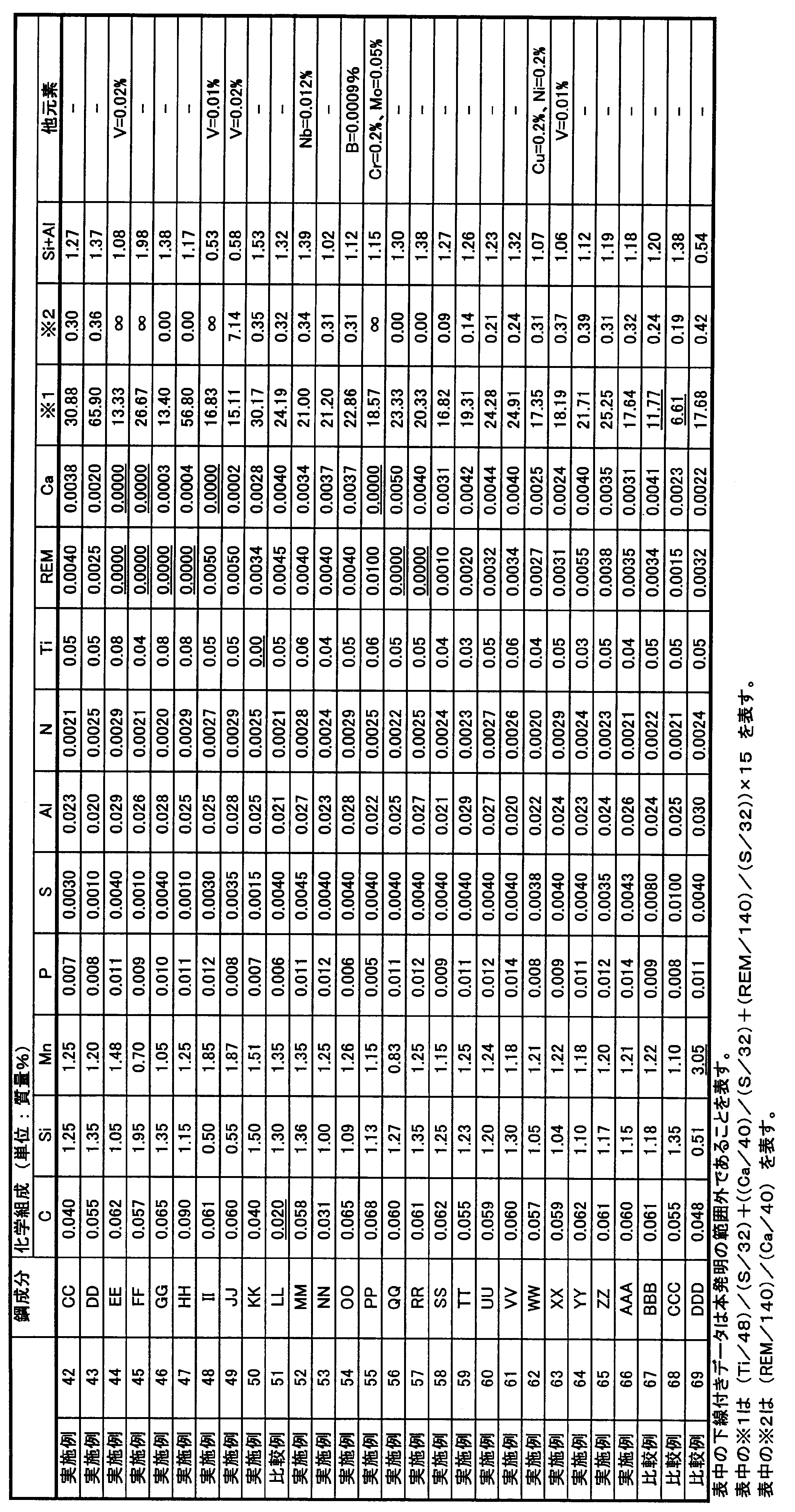

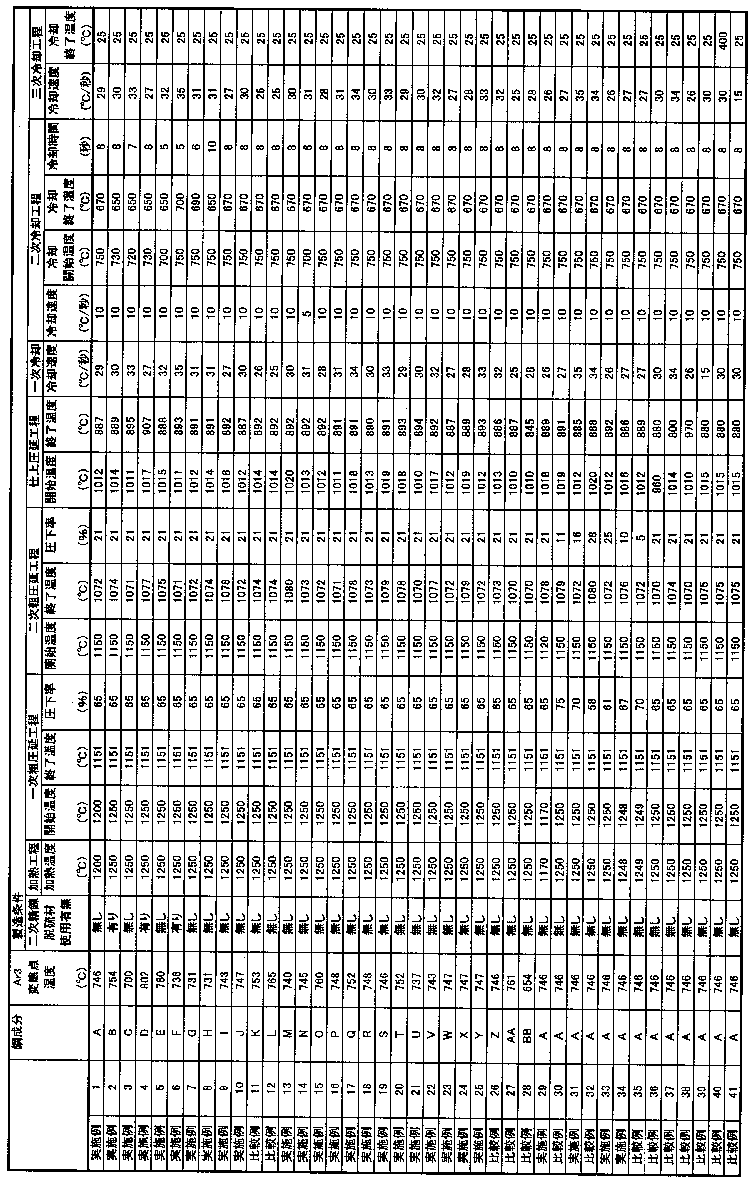


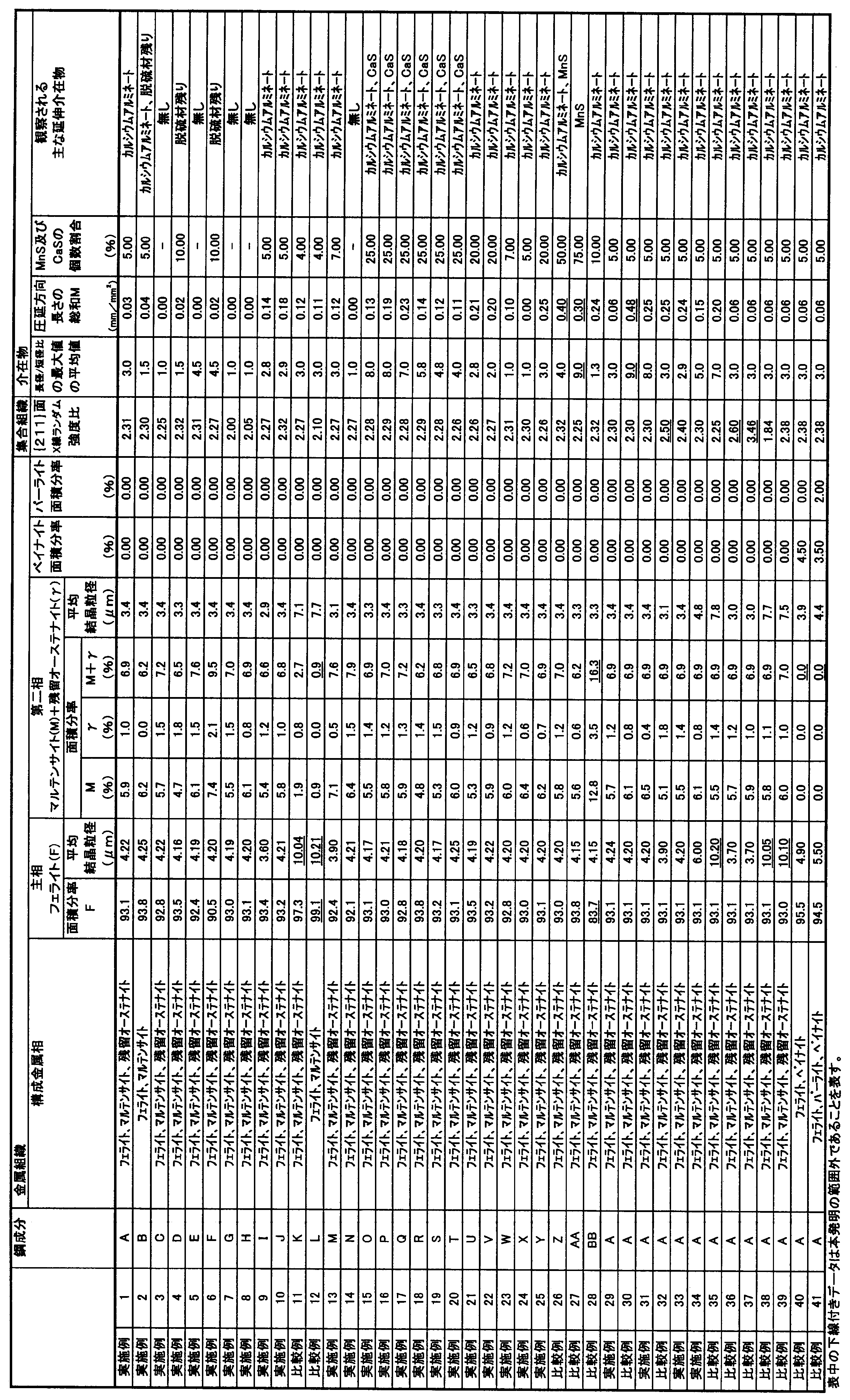
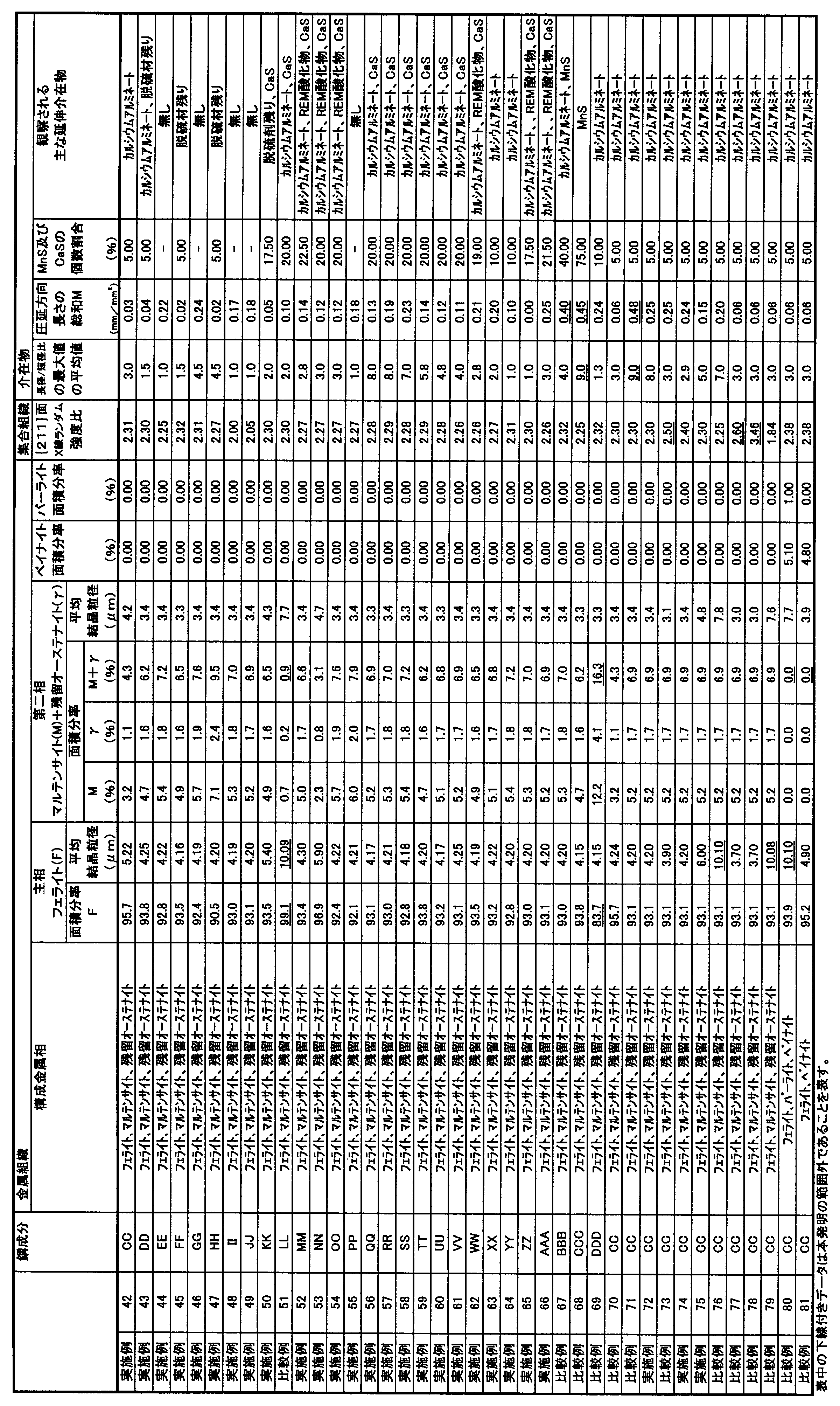


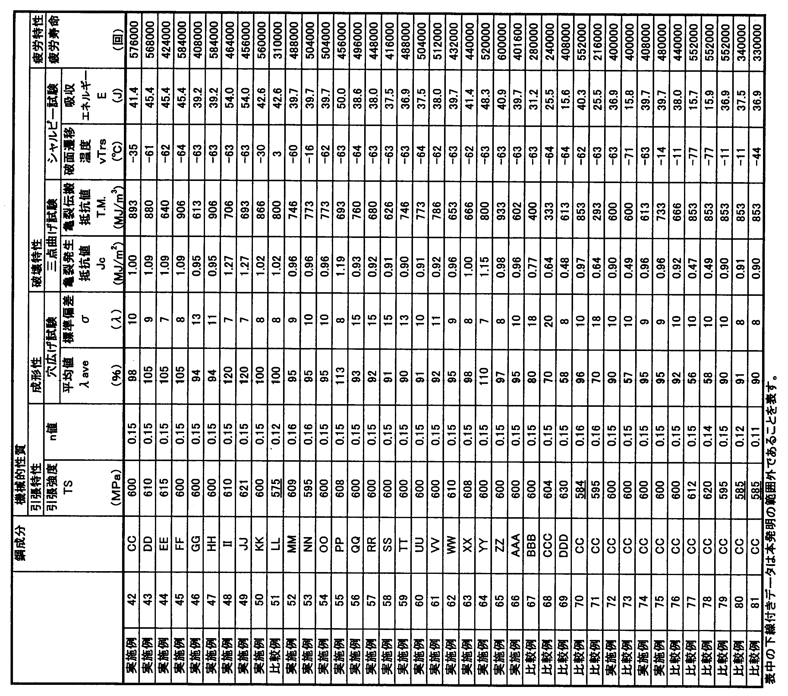
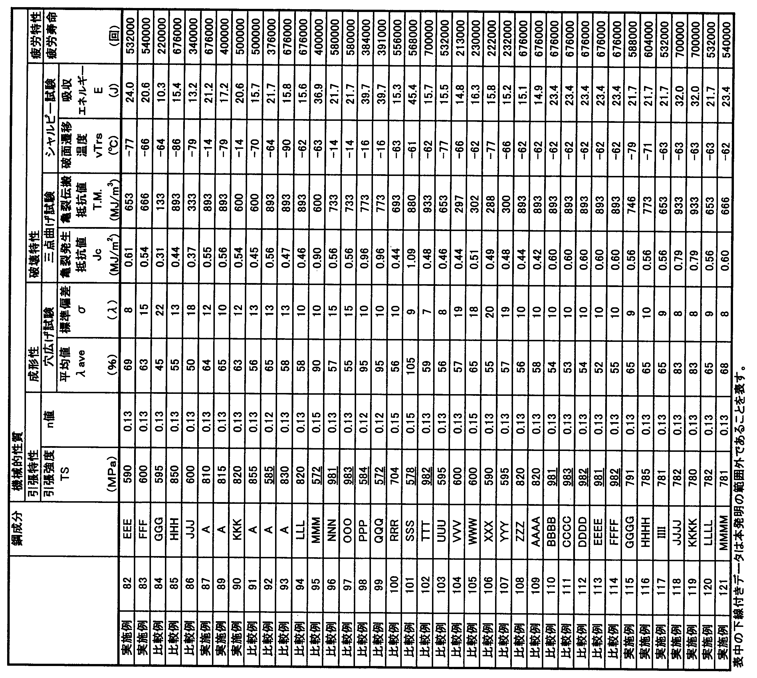
F 介在物間の圧延方向の間隔
G 介在物群、
GL 介在物群の圧延方向の長さ
H 独立介在物
HL 介在物群の圧延方向の長さ
Claims (9)
- 化学成分が、質量%で、
C :0.03%~0.1%、
Mn :0.5%~3.0%、
を含有し、
Si及びAlのうちの少なくとも1つが、
0.5%≦Si+Al≦4.0%
の条件を満たすように含有し、
P :0.1%以下、
S :0.01%以下、
N :0.02%以下、
に制限し、
Ti :0.001%~0.3%、
Rare Earth Metal:0.0001%~0.02%、
Ca :0.0001%~0.01%、
から選択された少なくとも1つを含有し、
残部がFe及び不可避的不純物からなり、
前記化学成分中の各元素の質量%で示した含有量が、下記の式1を満足し;
金属組織が、主相としてフェライトと、第二相としてマルテンサイト及び残留オーステナイトのうちの少なくとも一つと、複数の介在物と、を含み、
前記主相である前記フェライトの平均結晶粒径が2μm以上10μm以下であり、
前記主相である前記フェライトの面積分率が、90%以上99%以下であり、
前記第二相である前記マルテンサイトと前記残留オーステナイトとの面積分率が、合計で、1%以上10%以下であり、
鋼板の板幅方向が法線となる断面を0.0025mm2の視野で30回観察したとき、前記各視野での前記介在物の長径/短径比の最大値を平均した値が、1.0以上8.0以下であり、
前記介在物間の圧延方向の間隔が50μm以下でそれぞれの長径が3μm以上である前記介在物の集合体を介在物群とし、前記間隔が50μm超である前記介在物を独立介在物としたとき、圧延方向の長さが30μm以上である前記介在物群と、圧延方向の長さが30μm以上である前記独立介在物との、圧延方向の長さの総和が、前記断面の1mm2当たり、0mm以上0.25mm以下であり;
集合組織が、圧延面と平行な{211}面のX線ランダム強度比で1.0以上2.4以下であり;
引張強度が590MPa以上980MPa以下である;
ことを特徴とする熱延鋼板。
12.0≦(Ti/48)/(S/32)+{(Ca/40)/(S/32)+(Rare Earth Metal/140)/(S/32)}×15≦150 ・・・ (式1) - 前記化学成分が、更に、質量%で、
Nb :0.001%~0.1%、
B :0.0001%~0.0040%、
Cu :0.001%~1.0%、
Cr :0.001%~1.0%、
Mo :0.001%~1.0%、
Ni :0.001%~1.0%、
V :0.001%~0.2%、
のうちの少なくとも1つを含有する
ことを特徴とする請求項1に記載の熱延鋼板。 - 前記化学成分が、質量%で、
Rare Earth Metal:0.0001%~0.02%、
Ca :0.0001%~0.01%、
のうちの少なくとも1つを含有するとき、前記Tiの含有量を、
Ti :0.001%~0.08%未満、
とする
ことを特徴とする請求項1又は2に記載の熱延鋼板。 - 前記化学成分中の各元素の質量%で示した含有量が、下記の式2を満足し;
前記各視野での前記介在物の前記長径/短径比の前記最大値を平均した前記値が、1.0以上3.0以下である;
ことを特徴とする請求項1又は2に記載の熱延鋼板。
0.3≦(Rare Earth Metal/140)/(Ca/40) ・・・ (式2) - 前記金属組織で、ベイナイト及びパーライトの面積分率が、合計で、0%以上5.0%未満である
ことを特徴とする請求項1又は2に記載の熱延鋼板。 - 長径が3μm以上である前記介在物の合計個数に対して、長径が3μm以上であるMnS析出物及びCaS析出物の個数が、合計で、0%以上70%未満である
ことを特徴とする請求項1又は2に記載の熱延鋼板。 - 前記第二相の平均結晶粒径が0.5μm以上8.0μm以下である
ことを特徴とする請求項1又は2に記載の熱延鋼板。 - 請求項1又は2に記載の前記化学成分からなる鋼片を1200℃以上1400℃以下に加熱する加熱工程と;
前記加熱工程後に前記鋼片に対して、1150℃超1400℃以下の温度域で、累積圧下率が10%以上70%以下となる粗圧延を行う一次粗圧延工程と;
前記一次粗圧延工程後に、1070℃超1150℃以下の温度域で、累積圧下率が10%以上25%以下となる粗圧延を行う二次粗圧延工程と;
前記二次粗圧延工程後に、開始温度が1000℃以上1070℃以下、終了温度がAr3+60℃以上Ar3+200℃以下となる仕上圧延を行って熱延鋼板を得る仕上圧延工程と;
前記仕上圧延工程後に前記熱延鋼板に対して、前記終了温度から、冷却速度が20℃/秒以上150℃/秒以下である冷却を行う一次冷却工程と;
前記一次冷却工程後に、650℃以上750℃以下の温度域で、冷却速度が1℃/秒以上15℃/秒以下、及び、冷却時間が1秒以上10秒以下である冷却を行う二次冷却工程と;
前記二次冷却工程後に、0℃以上200℃以下の温度域まで、冷却速度が20℃/秒以上150℃/秒以下である冷却を行う三次冷却工程と;
前記三次冷却工程後に、前記熱延鋼板を巻き取る巻取工程と;を備える
ことを特徴とする熱延鋼板の製造方法。 - 前記一次粗圧延工程で、前記累積圧下率が10%以上65%以下となる前記粗圧延を行うことを特徴とする請求項8に記載の熱延鋼板の製造方法。
Priority Applications (6)
| Application Number | Priority Date | Filing Date | Title |
|---|---|---|---|
| US14/004,858 US9732405B2 (en) | 2011-03-18 | 2012-03-16 | Hot rolled steel sheet and method of producing same |
| CN201280013216.0A CN103429779B (zh) | 2011-03-18 | 2012-03-16 | 热轧钢板及其制造方法 |
| BR112013023571-3A BR112013023571B1 (pt) | 2011-03-18 | 2012-03-16 | Chapa de aço laminada a quente e método de produção da mesma |
| JP2013505956A JP5440738B2 (ja) | 2011-03-18 | 2012-03-16 | 熱延鋼板及びその製造方法 |
| MX2013010664A MX354006B (es) | 2011-03-18 | 2012-03-16 | Lamina de acero laminada en caliente y proceso para producir la misma. |
| KR1020137023879A KR101570590B1 (ko) | 2011-03-18 | 2012-03-16 | 열연 강판 및 그 제조 방법 |
Applications Claiming Priority (4)
| Application Number | Priority Date | Filing Date | Title |
|---|---|---|---|
| JP2011-060909 | 2011-03-18 | ||
| JP2011060909 | 2011-03-18 | ||
| JP2011-064633 | 2011-03-23 | ||
| JP2011064633 | 2011-03-23 |
Publications (1)
| Publication Number | Publication Date |
|---|---|
| WO2012128228A1 true WO2012128228A1 (ja) | 2012-09-27 |
Family
ID=46879375
Family Applications (1)
| Application Number | Title | Priority Date | Filing Date |
|---|---|---|---|
| PCT/JP2012/056927 Ceased WO2012128228A1 (ja) | 2011-03-18 | 2012-03-16 | 熱延鋼板及びその製造方法 |
Country Status (8)
| Country | Link |
|---|---|
| US (1) | US9732405B2 (ja) |
| JP (1) | JP5440738B2 (ja) |
| KR (1) | KR101570590B1 (ja) |
| CN (1) | CN103429779B (ja) |
| BR (1) | BR112013023571B1 (ja) |
| MX (1) | MX354006B (ja) |
| TW (1) | TWI460290B (ja) |
| WO (1) | WO2012128228A1 (ja) |
Cited By (15)
| Publication number | Priority date | Publication date | Assignee | Title |
|---|---|---|---|---|
| WO2014091554A1 (ja) * | 2012-12-11 | 2014-06-19 | 新日鐵住金株式会社 | 熱延鋼板およびその製造方法 |
| JP2014141703A (ja) * | 2013-01-23 | 2014-08-07 | Nippon Steel & Sumitomo Metal | 外観に優れ、伸びと穴拡げ性のバランスに優れた高強度熱延鋼板及びその製造方法 |
| WO2014119260A1 (ja) * | 2013-01-31 | 2014-08-07 | Jfeスチール株式会社 | 高強度熱延鋼板およびその製造方法 |
| WO2014123229A1 (ja) * | 2013-02-08 | 2014-08-14 | 新日鐵住金ステンレス株式会社 | ステンレス鋼製ブレーキディスクとその製造方法 |
| JP2014185359A (ja) * | 2013-03-22 | 2014-10-02 | Jfe Steel Corp | 高強度鋼板 |
| JP2015528858A (ja) * | 2012-08-03 | 2015-10-01 | タタ、スティール、アイモイデン、ベスローテン、フェンノートシャップTata Steel Ijmuiden Bv | 熱間圧延鋼ストリップを製造するためのプロセスおよびそれにより製造された鋼ストリップ |
| US10301698B2 (en) | 2012-01-31 | 2019-05-28 | Jfe Steel Corporation | Hot-rolled steel sheet for generator rim and method for manufacturing the same |
| US10513749B2 (en) | 2014-05-28 | 2019-12-24 | Nippon Steel Corporation | Hot-rolled steel sheet and production method of therefor |
| EP3502292A4 (en) * | 2016-08-18 | 2020-03-04 | Nippon Steel Corporation | HOT ROLLED STEEL SHEET |
| JP2021099273A (ja) * | 2019-12-23 | 2021-07-01 | 信越半導体株式会社 | 標準サンプルおよびその作製方法、ならびにebsd測定装置の管理方法 |
| KR20210107826A (ko) * | 2019-03-26 | 2021-09-01 | 닛폰세이테츠 가부시키가이샤 | 강판, 강판의 제조 방법 및 도금 강판 |
| WO2022091489A1 (ja) | 2020-10-28 | 2022-05-05 | 日本製鉄株式会社 | 熱間圧延鋼板 |
| CN114752744A (zh) * | 2022-04-15 | 2022-07-15 | 武汉科技大学 | 减小大方坯硅锰脱氧钢棒线材夹杂物特征尺寸的方法 |
| US12116646B2 (en) | 2020-03-11 | 2024-10-15 | Nippon Steel Corporation | Hot-rolled steel sheet |
| US12123064B2 (en) | 2019-03-06 | 2024-10-22 | Nippon Steel Corporation | Hot-rolled steel sheet |
Families Citing this family (10)
| Publication number | Priority date | Publication date | Assignee | Title |
|---|---|---|---|---|
| TWI509087B (zh) * | 2014-07-21 | 2015-11-21 | China Steel Corp | High strength hot rolled steel |
| BR112017004711A2 (pt) * | 2014-09-17 | 2017-12-05 | Nippon Steel & Sumitomo Metal Corp | chapa de aço laminada a quente |
| WO2016143812A1 (ja) * | 2015-03-09 | 2016-09-15 | 新日鐵住金株式会社 | 熱間圧延鋼材および鋼部品 |
| CN105821301A (zh) * | 2016-04-21 | 2016-08-03 | 河北钢铁股份有限公司邯郸分公司 | 一种800MPa级热轧高强度扩孔钢及其生产方法 |
| CN109211695A (zh) * | 2017-07-07 | 2019-01-15 | 中国石油化工股份有限公司 | 一种金属管材断裂韧度的检测方法及系统 |
| RU2687360C1 (ru) * | 2018-07-19 | 2019-05-13 | Публичное акционерное общество "Северсталь" (ПАО "Северсталь") | Стальной прокат повышенной коррозионной стойкости и изделие, выполненное из него |
| CN109910416B (zh) * | 2019-01-31 | 2020-08-28 | 武汉科技大学 | 一种钢板防腐蚀防辐射方法 |
| CN110669986B (zh) * | 2019-10-17 | 2021-09-07 | 浦项(张家港)不锈钢股份有限公司 | 一种310s不锈钢制备方法及310s不锈钢 |
| JP7260824B2 (ja) * | 2020-01-27 | 2023-04-19 | 日本製鉄株式会社 | 熱延鋼板 |
| TWI857810B (zh) * | 2023-10-19 | 2024-10-01 | 財團法人金屬工業研究發展中心 | 鑄鐵件的尺寸穩定化方法 |
Citations (4)
| Publication number | Priority date | Publication date | Assignee | Title |
|---|---|---|---|---|
| JP2008138231A (ja) * | 2006-11-30 | 2008-06-19 | Nippon Steel Corp | 穴広げ性に優れた熱延複合組織鋼板およびその製造方法 |
| JP2009024227A (ja) * | 2007-07-20 | 2009-02-05 | Nippon Steel Corp | 成形性に優れる複合組織鋼板およびその製造方法 |
| JP2010090476A (ja) * | 2008-09-11 | 2010-04-22 | Nippon Steel Corp | 穴広げ性に優れた高強度熱延鋼板及びその製造方法 |
| WO2011111758A1 (ja) * | 2010-03-10 | 2011-09-15 | 新日本製鐵株式会社 | 高強度熱延鋼板及びその製造方法 |
Family Cites Families (6)
| Publication number | Priority date | Publication date | Assignee | Title |
|---|---|---|---|---|
| JPH06145792A (ja) | 1992-11-12 | 1994-05-27 | Kobe Steel Ltd | 疲労特性と加工性の良好な590N/mm2以上の強度を有する高強度熱延鋼板の製造方法 |
| JP3284035B2 (ja) | 1995-10-31 | 2002-05-20 | 川崎製鉄株式会社 | 伸びフランジ性に優れる高強度熱延鋼板およびその製造方法 |
| JP4051999B2 (ja) * | 2001-06-19 | 2008-02-27 | Jfeスチール株式会社 | 形状凍結性と成形後の耐久疲労特性に優れた高張力熱延鋼板およびその製造方法 |
| US7780797B2 (en) * | 2002-12-26 | 2010-08-24 | Nippon Steel Corporation | High strength thin steel excellent in hole expansibility, ductility and chemical treatment characteristics |
| JP4555694B2 (ja) * | 2005-01-18 | 2010-10-06 | 新日本製鐵株式会社 | 加工性に優れる焼付け硬化型熱延鋼板およびその製造方法 |
| JP5194811B2 (ja) * | 2007-03-30 | 2013-05-08 | Jfeスチール株式会社 | 高強度溶融亜鉛めっき鋼板 |
-
2012
- 2012-03-16 MX MX2013010664A patent/MX354006B/es active IP Right Grant
- 2012-03-16 BR BR112013023571-3A patent/BR112013023571B1/pt active IP Right Grant
- 2012-03-16 KR KR1020137023879A patent/KR101570590B1/ko active Active
- 2012-03-16 CN CN201280013216.0A patent/CN103429779B/zh active Active
- 2012-03-16 WO PCT/JP2012/056927 patent/WO2012128228A1/ja not_active Ceased
- 2012-03-16 JP JP2013505956A patent/JP5440738B2/ja active Active
- 2012-03-16 US US14/004,858 patent/US9732405B2/en active Active
- 2012-03-16 TW TW101109250A patent/TWI460290B/zh not_active IP Right Cessation
Patent Citations (4)
| Publication number | Priority date | Publication date | Assignee | Title |
|---|---|---|---|---|
| JP2008138231A (ja) * | 2006-11-30 | 2008-06-19 | Nippon Steel Corp | 穴広げ性に優れた熱延複合組織鋼板およびその製造方法 |
| JP2009024227A (ja) * | 2007-07-20 | 2009-02-05 | Nippon Steel Corp | 成形性に優れる複合組織鋼板およびその製造方法 |
| JP2010090476A (ja) * | 2008-09-11 | 2010-04-22 | Nippon Steel Corp | 穴広げ性に優れた高強度熱延鋼板及びその製造方法 |
| WO2011111758A1 (ja) * | 2010-03-10 | 2011-09-15 | 新日本製鐵株式会社 | 高強度熱延鋼板及びその製造方法 |
Cited By (26)
| Publication number | Priority date | Publication date | Assignee | Title |
|---|---|---|---|---|
| US10301698B2 (en) | 2012-01-31 | 2019-05-28 | Jfe Steel Corporation | Hot-rolled steel sheet for generator rim and method for manufacturing the same |
| JP2015528858A (ja) * | 2012-08-03 | 2015-10-01 | タタ、スティール、アイモイデン、ベスローテン、フェンノートシャップTata Steel Ijmuiden Bv | 熱間圧延鋼ストリップを製造するためのプロセスおよびそれにより製造された鋼ストリップ |
| JPWO2014091554A1 (ja) * | 2012-12-11 | 2017-01-05 | 新日鐵住金株式会社 | 熱延鋼板およびその製造方法 |
| US10273566B2 (en) | 2012-12-11 | 2019-04-30 | Nippon Steel & Sumitomo Metal Corporation | Hot-rolled steel sheet and method for producing same |
| WO2014091554A1 (ja) * | 2012-12-11 | 2014-06-19 | 新日鐵住金株式会社 | 熱延鋼板およびその製造方法 |
| KR101744429B1 (ko) * | 2012-12-11 | 2017-06-07 | 신닛테츠스미킨 카부시키카이샤 | 열연 강판 및 그 제조 방법 |
| JP2014141703A (ja) * | 2013-01-23 | 2014-08-07 | Nippon Steel & Sumitomo Metal | 外観に優れ、伸びと穴拡げ性のバランスに優れた高強度熱延鋼板及びその製造方法 |
| WO2014119260A1 (ja) * | 2013-01-31 | 2014-08-07 | Jfeスチール株式会社 | 高強度熱延鋼板およびその製造方法 |
| CN104968820A (zh) * | 2013-01-31 | 2015-10-07 | 杰富意钢铁株式会社 | 高强度热轧钢板及其制造方法 |
| CN104321456A (zh) * | 2013-02-08 | 2015-01-28 | 新日铁住金不锈钢株式会社 | 不锈钢制制动盘及其制造方法 |
| US9523402B2 (en) | 2013-02-08 | 2016-12-20 | Nippon Steel & Sumikin Stainless Steel Corporation | Stainless steel brake disc and method for production thereof |
| WO2014123229A1 (ja) * | 2013-02-08 | 2014-08-14 | 新日鐵住金ステンレス株式会社 | ステンレス鋼製ブレーキディスクとその製造方法 |
| JP2014185359A (ja) * | 2013-03-22 | 2014-10-02 | Jfe Steel Corp | 高強度鋼板 |
| US10513749B2 (en) | 2014-05-28 | 2019-12-24 | Nippon Steel Corporation | Hot-rolled steel sheet and production method of therefor |
| US11255005B2 (en) | 2016-08-18 | 2022-02-22 | Nippon Steel Corporation | Hot-rolled steel sheet |
| EP3502292A4 (en) * | 2016-08-18 | 2020-03-04 | Nippon Steel Corporation | HOT ROLLED STEEL SHEET |
| US12123064B2 (en) | 2019-03-06 | 2024-10-22 | Nippon Steel Corporation | Hot-rolled steel sheet |
| KR102599382B1 (ko) | 2019-03-26 | 2023-11-08 | 닛폰세이테츠 가부시키가이샤 | 강판, 강판의 제조 방법 및 도금 강판 |
| KR20210107826A (ko) * | 2019-03-26 | 2021-09-01 | 닛폰세이테츠 가부시키가이샤 | 강판, 강판의 제조 방법 및 도금 강판 |
| JP7188377B2 (ja) | 2019-12-23 | 2022-12-13 | 信越半導体株式会社 | 標準サンプルおよびその作製方法、ならびにebsd測定装置の管理方法 |
| JP2021099273A (ja) * | 2019-12-23 | 2021-07-01 | 信越半導体株式会社 | 標準サンプルおよびその作製方法、ならびにebsd測定装置の管理方法 |
| US12116646B2 (en) | 2020-03-11 | 2024-10-15 | Nippon Steel Corporation | Hot-rolled steel sheet |
| WO2022091489A1 (ja) | 2020-10-28 | 2022-05-05 | 日本製鉄株式会社 | 熱間圧延鋼板 |
| KR20230009971A (ko) | 2020-10-28 | 2023-01-17 | 닛폰세이테츠 가부시키가이샤 | 열간 압연 강판 |
| US12559808B2 (en) | 2020-10-28 | 2026-02-24 | Nippon Steel Corporation | Hot rolled steel sheet |
| CN114752744A (zh) * | 2022-04-15 | 2022-07-15 | 武汉科技大学 | 减小大方坯硅锰脱氧钢棒线材夹杂物特征尺寸的方法 |
Also Published As
| Publication number | Publication date |
|---|---|
| TW201243063A (en) | 2012-11-01 |
| US9732405B2 (en) | 2017-08-15 |
| BR112013023571A2 (pt) | 2016-12-06 |
| TWI460290B (zh) | 2014-11-11 |
| CN103429779A (zh) | 2013-12-04 |
| KR101570590B1 (ko) | 2015-11-19 |
| JP5440738B2 (ja) | 2014-03-12 |
| KR20130123438A (ko) | 2013-11-12 |
| MX2013010664A (es) | 2013-10-28 |
| MX354006B (es) | 2018-02-08 |
| JPWO2012128228A1 (ja) | 2014-07-24 |
| US20140000769A1 (en) | 2014-01-02 |
| CN103429779B (zh) | 2015-06-03 |
| BR112013023571B1 (pt) | 2019-05-21 |
Similar Documents
| Publication | Publication Date | Title |
|---|---|---|
| JP5440738B2 (ja) | 熱延鋼板及びその製造方法 | |
| JP4842413B2 (ja) | 高強度熱延鋼板及びその製造方法 | |
| JP5896086B1 (ja) | 高降伏比高強度冷延鋼板およびその製造方法 | |
| CN113637923B (zh) | 钢板及镀覆钢板 | |
| JP5858174B2 (ja) | 低降伏比高強度冷延鋼板およびその製造方法 | |
| JP6319442B2 (ja) | 熱延鋼板 | |
| EP2987884A1 (en) | Hot-rolled steel sheet | |
| JP6687167B2 (ja) | 熱延鋼板及びその製造方法 | |
| JP5720612B2 (ja) | 成形性及び低温靭性に優れた高強度熱延鋼板及びその製造方法 | |
| JPWO2014185405A1 (ja) | 熱延鋼板およびその製造方法 | |
| WO2009110607A1 (ja) | 冷延鋼板 | |
| CN109415785B (zh) | 钢板 | |
| KR20120023129A (ko) | 고강도 강판 및 그 제조 방법 | |
| KR20130121940A (ko) | 가공성이 우수한 고항복비를 갖는 고강도 냉연 강판 및 그 제조 방법 | |
| JP2010090476A (ja) | 穴広げ性に優れた高強度熱延鋼板及びその製造方法 | |
| JP2014019928A (ja) | 高強度冷延鋼板および高強度冷延鋼板の製造方法 | |
| JP7188618B2 (ja) | 熱延鋼板 | |
| JP5786820B2 (ja) | 成形性、破壊特性及び疲労特性に優れた熱延鋼板及びその製造方法 | |
| JP5668588B2 (ja) | 成形性及び破壊特性に優れた高強度熱延鋼板及びその製造方法 | |
| JP6668662B2 (ja) | 疲労特性と成形性に優れた鋼板およびその製造方法 | |
| JP2024151196A (ja) | 鋼板およびその製造方法 |
Legal Events
| Date | Code | Title | Description |
|---|---|---|---|
| 121 | Ep: the epo has been informed by wipo that ep was designated in this application |
Ref document number: 12759942 Country of ref document: EP Kind code of ref document: A1 |
|
| ENP | Entry into the national phase |
Ref document number: 2013505956 Country of ref document: JP Kind code of ref document: A |
|
| ENP | Entry into the national phase |
Ref document number: 20137023879 Country of ref document: KR Kind code of ref document: A |
|
| WWE | Wipo information: entry into national phase |
Ref document number: 14004858 Country of ref document: US |
|
| NENP | Non-entry into the national phase |
Ref country code: DE |
|
| WWE | Wipo information: entry into national phase |
Ref document number: 1301005144 Country of ref document: TH Ref document number: MX/A/2013/010664 Country of ref document: MX |
|
| REG | Reference to national code |
Ref country code: BR Ref legal event code: B01A Ref document number: 112013023571 Country of ref document: BR |
|
| 122 | Ep: pct application non-entry in european phase |
Ref document number: 12759942 Country of ref document: EP Kind code of ref document: A1 |
|
| ENP | Entry into the national phase |
Ref document number: 112013023571 Country of ref document: BR Kind code of ref document: A2 Effective date: 20130913 |