WO2012128052A1 - 固体電解コンデンサ - Google Patents
固体電解コンデンサ Download PDFInfo
- Publication number
- WO2012128052A1 WO2012128052A1 PCT/JP2012/055908 JP2012055908W WO2012128052A1 WO 2012128052 A1 WO2012128052 A1 WO 2012128052A1 JP 2012055908 W JP2012055908 W JP 2012055908W WO 2012128052 A1 WO2012128052 A1 WO 2012128052A1
- Authority
- WO
- WIPO (PCT)
- Prior art keywords
- repeating unit
- electrolytic capacitor
- solid electrolytic
- solid electrolyte
- weight
- Prior art date
Links
- 239000003990 capacitor Substances 0.000 title claims abstract description 102
- 239000007784 solid electrolyte Substances 0.000 title claims abstract description 52
- 229920001940 conductive polymer Polymers 0.000 claims abstract description 17
- 125000000217 alkyl group Chemical group 0.000 claims abstract description 6
- 125000003808 silyl group Chemical group [H][Si]([H])([H])[*] 0.000 claims abstract description 4
- 239000007787 solid Substances 0.000 claims description 80
- 239000011248 coating agent Substances 0.000 claims description 9
- 238000000576 coating method Methods 0.000 claims description 9
- 125000004432 carbon atom Chemical group C* 0.000 claims description 5
- 125000000547 substituted alkyl group Chemical group 0.000 claims description 4
- 125000005156 substituted alkylene group Chemical group 0.000 claims description 3
- 125000002947 alkylene group Chemical group 0.000 abstract description 2
- 239000000178 monomer Substances 0.000 description 59
- 239000000243 solution Substances 0.000 description 29
- 229910052751 metal Inorganic materials 0.000 description 24
- 239000002184 metal Substances 0.000 description 24
- 238000006116 polymerization reaction Methods 0.000 description 23
- 239000011888 foil Substances 0.000 description 20
- 230000000052 comparative effect Effects 0.000 description 19
- LFQSCWFLJHTTHZ-UHFFFAOYSA-N Ethanol Chemical compound CCO LFQSCWFLJHTTHZ-UHFFFAOYSA-N 0.000 description 17
- 239000002019 doping agent Substances 0.000 description 17
- 238000004804 winding Methods 0.000 description 11
- 229910052782 aluminium Inorganic materials 0.000 description 10
- XAGFODPZIPBFFR-UHFFFAOYSA-N aluminium Chemical compound [Al] XAGFODPZIPBFFR-UHFFFAOYSA-N 0.000 description 10
- -1 polyethylene terephthalate Polymers 0.000 description 10
- 239000000203 mixture Substances 0.000 description 9
- 239000000126 substance Substances 0.000 description 9
- 229920001577 copolymer Polymers 0.000 description 8
- 238000000034 method Methods 0.000 description 8
- 230000008859 change Effects 0.000 description 7
- 238000007789 sealing Methods 0.000 description 7
- 238000006243 chemical reaction Methods 0.000 description 6
- 239000000463 material Substances 0.000 description 6
- 229920000642 polymer Polymers 0.000 description 6
- 238000012360 testing method Methods 0.000 description 6
- 238000004519 manufacturing process Methods 0.000 description 5
- 229920001971 elastomer Polymers 0.000 description 4
- 239000007788 liquid Substances 0.000 description 4
- 239000002904 solvent Substances 0.000 description 4
- WEVYAHXRMPXWCK-UHFFFAOYSA-N Acetonitrile Chemical compound CC#N WEVYAHXRMPXWCK-UHFFFAOYSA-N 0.000 description 3
- LSNNMFCWUKXFEE-UHFFFAOYSA-M Bisulfite Chemical compound OS([O-])=O LSNNMFCWUKXFEE-UHFFFAOYSA-M 0.000 description 3
- OKKJLVBELUTLKV-UHFFFAOYSA-N Methanol Chemical compound OC OKKJLVBELUTLKV-UHFFFAOYSA-N 0.000 description 3
- 230000009471 action Effects 0.000 description 3
- 238000005530 etching Methods 0.000 description 3
- WABPQHHGFIMREM-UHFFFAOYSA-N lead(0) Chemical compound [Pb] WABPQHHGFIMREM-UHFFFAOYSA-N 0.000 description 3
- 229910052758 niobium Inorganic materials 0.000 description 3
- 239000010955 niobium Substances 0.000 description 3
- GUCVJGMIXFAOAE-UHFFFAOYSA-N niobium atom Chemical compound [Nb] GUCVJGMIXFAOAE-UHFFFAOYSA-N 0.000 description 3
- 150000003839 salts Chemical class 0.000 description 3
- 229910052715 tantalum Inorganic materials 0.000 description 3
- GUVRBAGPIYLISA-UHFFFAOYSA-N tantalum atom Chemical compound [Ta] GUVRBAGPIYLISA-UHFFFAOYSA-N 0.000 description 3
- CSCPPACGZOOCGX-UHFFFAOYSA-N Acetone Chemical compound CC(C)=O CSCPPACGZOOCGX-UHFFFAOYSA-N 0.000 description 2
- XEEYBQQBJWHFJM-UHFFFAOYSA-N Iron Chemical compound [Fe] XEEYBQQBJWHFJM-UHFFFAOYSA-N 0.000 description 2
- OFBQJSOFQDEBGM-UHFFFAOYSA-N Pentane Chemical compound CCCCC OFBQJSOFQDEBGM-UHFFFAOYSA-N 0.000 description 2
- WYURNTSHIVDZCO-UHFFFAOYSA-N Tetrahydrofuran Chemical compound C1CCOC1 WYURNTSHIVDZCO-UHFFFAOYSA-N 0.000 description 2
- 238000005259 measurement Methods 0.000 description 2
- 239000007800 oxidant agent Substances 0.000 description 2
- 230000009467 reduction Effects 0.000 description 2
- 238000012916 structural analysis Methods 0.000 description 2
- JOXIMZWYDAKGHI-UHFFFAOYSA-M toluene-4-sulfonate Chemical compound CC1=CC=C(S([O-])(=O)=O)C=C1 JOXIMZWYDAKGHI-UHFFFAOYSA-M 0.000 description 2
- FLDCSPABIQBYKP-UHFFFAOYSA-N 5-chloro-1,2-dimethylbenzimidazole Chemical compound ClC1=CC=C2N(C)C(C)=NC2=C1 FLDCSPABIQBYKP-UHFFFAOYSA-N 0.000 description 1
- 239000001741 Ammonium adipate Substances 0.000 description 1
- 229910001369 Brass Inorganic materials 0.000 description 1
- 239000004215 Carbon black (E152) Substances 0.000 description 1
- RYGMFSIKBFXOCR-UHFFFAOYSA-N Copper Chemical compound [Cu] RYGMFSIKBFXOCR-UHFFFAOYSA-N 0.000 description 1
- 229920000181 Ethylene propylene rubber Polymers 0.000 description 1
- YCKRFDGAMUMZLT-UHFFFAOYSA-N Fluorine atom Chemical compound [F] YCKRFDGAMUMZLT-UHFFFAOYSA-N 0.000 description 1
- XBDQKXXYIPTUBI-UHFFFAOYSA-M Propionate Chemical compound CCC([O-])=O XBDQKXXYIPTUBI-UHFFFAOYSA-M 0.000 description 1
- 229920002978 Vinylon Polymers 0.000 description 1
- 230000032683 aging Effects 0.000 description 1
- 239000005456 alcohol based solvent Substances 0.000 description 1
- 125000003545 alkoxy group Chemical group 0.000 description 1
- 229910045601 alloy Inorganic materials 0.000 description 1
- 239000000956 alloy Substances 0.000 description 1
- 235000019293 ammonium adipate Nutrition 0.000 description 1
- 239000007864 aqueous solution Substances 0.000 description 1
- 239000004760 aramid Substances 0.000 description 1
- 229920006231 aramid fiber Polymers 0.000 description 1
- 230000015572 biosynthetic process Effects 0.000 description 1
- 239000010951 brass Substances 0.000 description 1
- 229920005549 butyl rubber Polymers 0.000 description 1
- 238000004364 calculation method Methods 0.000 description 1
- 229920002678 cellulose Polymers 0.000 description 1
- 239000001913 cellulose Substances 0.000 description 1
- 150000001875 compounds Chemical class 0.000 description 1
- 238000007334 copolymerization reaction Methods 0.000 description 1
- 229910052802 copper Inorganic materials 0.000 description 1
- 239000010949 copper Substances 0.000 description 1
- 239000003792 electrolyte Substances 0.000 description 1
- 239000003759 ester based solvent Substances 0.000 description 1
- 239000004210 ether based solvent Substances 0.000 description 1
- 238000011156 evaluation Methods 0.000 description 1
- 239000011737 fluorine Substances 0.000 description 1
- 229910052731 fluorine Inorganic materials 0.000 description 1
- WBJINCZRORDGAQ-UHFFFAOYSA-N formic acid ethyl ester Natural products CCOC=O WBJINCZRORDGAQ-UHFFFAOYSA-N 0.000 description 1
- 229930195733 hydrocarbon Natural products 0.000 description 1
- 150000002430 hydrocarbons Chemical class 0.000 description 1
- 230000006872 improvement Effects 0.000 description 1
- 229910052742 iron Inorganic materials 0.000 description 1
- 229920003049 isoprene rubber Polymers 0.000 description 1
- 239000005453 ketone based solvent Substances 0.000 description 1
- 238000010030 laminating Methods 0.000 description 1
- 229910021645 metal ion Inorganic materials 0.000 description 1
- HLANOUYSOJLOPM-UHFFFAOYSA-N methoxy benzenesulfonate Chemical compound COOS(=O)(=O)C1=CC=CC=C1 HLANOUYSOJLOPM-UHFFFAOYSA-N 0.000 description 1
- 238000012986 modification Methods 0.000 description 1
- 230000004048 modification Effects 0.000 description 1
- QJGQUHMNIGDVPM-UHFFFAOYSA-N nitrogen group Chemical group [N] QJGQUHMNIGDVPM-UHFFFAOYSA-N 0.000 description 1
- 239000004745 nonwoven fabric Substances 0.000 description 1
- 239000003960 organic solvent Substances 0.000 description 1
- 238000012856 packing Methods 0.000 description 1
- 229920000139 polyethylene terephthalate Polymers 0.000 description 1
- 239000005020 polyethylene terephthalate Substances 0.000 description 1
- 239000002861 polymer material Substances 0.000 description 1
- 230000004044 response Effects 0.000 description 1
- 229920002379 silicone rubber Polymers 0.000 description 1
- 239000010935 stainless steel Substances 0.000 description 1
- 229910001220 stainless steel Inorganic materials 0.000 description 1
- 125000001174 sulfone group Chemical group 0.000 description 1
- YLQBMQCUIZJEEH-UHFFFAOYSA-N tetrahydrofuran Natural products C=1C=COC=1 YLQBMQCUIZJEEH-UHFFFAOYSA-N 0.000 description 1
Images


Classifications
-
- H—ELECTRICITY
- H01—ELECTRIC ELEMENTS
- H01G—CAPACITORS; CAPACITORS, RECTIFIERS, DETECTORS, SWITCHING DEVICES, LIGHT-SENSITIVE OR TEMPERATURE-SENSITIVE DEVICES OF THE ELECTROLYTIC TYPE
- H01G9/00—Electrolytic capacitors, rectifiers, detectors, switching devices, light-sensitive or temperature-sensitive devices; Processes of their manufacture
- H01G9/004—Details
- H01G9/022—Electrolytes; Absorbents
- H01G9/025—Solid electrolytes
- H01G9/028—Organic semiconducting electrolytes, e.g. TCNQ
-
- H—ELECTRICITY
- H01—ELECTRIC ELEMENTS
- H01G—CAPACITORS; CAPACITORS, RECTIFIERS, DETECTORS, SWITCHING DEVICES, LIGHT-SENSITIVE OR TEMPERATURE-SENSITIVE DEVICES OF THE ELECTROLYTIC TYPE
- H01G9/00—Electrolytic capacitors, rectifiers, detectors, switching devices, light-sensitive or temperature-sensitive devices; Processes of their manufacture
- H01G9/15—Solid electrolytic capacitors
Definitions
- the present invention relates to a solid electrolytic capacitor, and more particularly to a solid electrolytic capacitor including a solid electrolyte made of a conductive polymer.
- solid electrolytic capacitors are widely known as capacitors suitable for miniaturization.
- a solid body comprising a sintered body made of a valve action metal such as niobium, tantalum and aluminum, or a foil made of the valve action metal whose surface is roughened by etching or the like as an anode body.
- an electrolytic capacitor Such a solid electrolytic capacitor can be provided with an anode body having a large surface area, so that the surface of the dielectric film can be expanded, and as a result, it is possible to reduce the size and increase the capacity.
- a solid electrolytic capacitor including a solid electrolyte made of a conductive polymer is small, has a large capacity, has a low equivalent series resistance (hereinafter referred to as “ESR”), and is excellent in characteristics such as being suitable for surface mounting. ing. For this reason, a solid electrolytic capacitor including a solid electrolyte made of a conductive polymer is an element indispensable for downsizing, high functionality, and cost reduction of electronic devices.
- Patent Documents 1 and 2 describe a conductive polymer material capable of improving characteristics such as conductivity and ESR of a solid electrolytic capacitor.
- an object of the present invention is to provide a high performance solid electrolytic capacitor.
- the present invention includes an anode body provided with a dielectric coating on the surface thereof, a cathode body, and a solid electrolyte provided between the anode body and the cathode body.
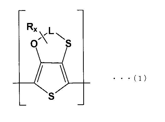
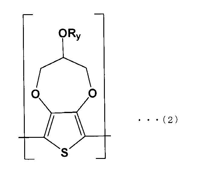
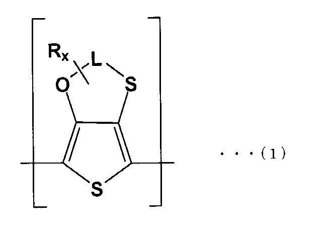
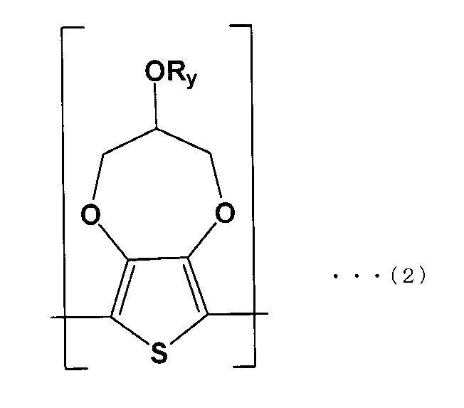
- the solid electrolyte is represented by the following formula (1). It is a solid electrolytic capacitor which is a conductive polymer containing the first repeating unit (A) and the second repeating unit (B) of the following formula (2).
- the ratio (A: B) of the weight of the first repeating unit (A) to the weight of the second repeating unit (B) is 1: 1 or more and 9: 1 or less in the conductive polymer. Preferably there is.
- the ratio (A: B) of the weight of the first repeating unit (A) to the weight of the second repeating unit (B) in the conductive polymer is preferably 3: 2 or more. .
- the ratio (A: B) of the weight of the first repeating unit (A) to the weight of the second repeating unit (B) is preferably 7: 3 or less.
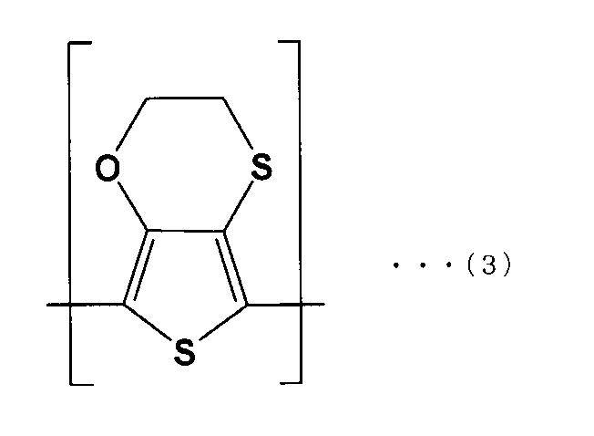
- the first repeating unit (A) preferably has a structure represented by the following formula (3)
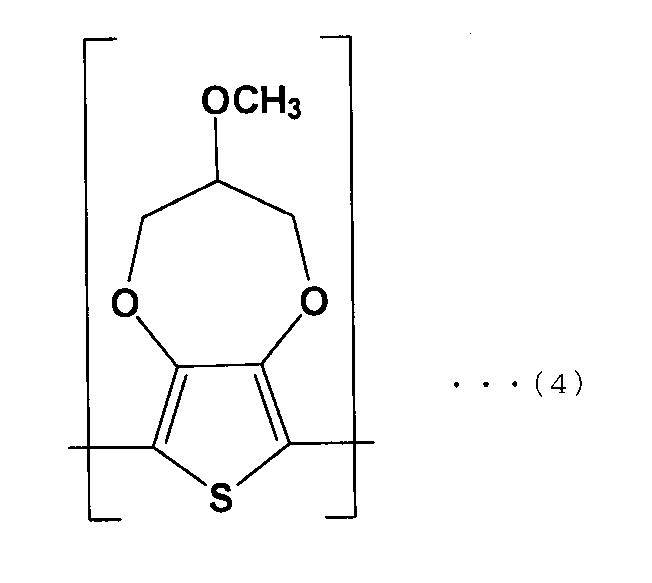
- the second repeating unit (B) preferably has a structure represented by the following formula (4).
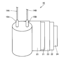
- a solid electrolytic capacitor 100 includes a capacitor element 10, a bottomed case 11, a sealing member 12, a seat plate 13, lead wires 14A and 14B, and lead tabs 15A and 15B.
- Lead tabs 15A and 15B are connected to the capacitor element 10, and lead wires 14A and 14B are electrically connected to the lead tabs 15A and 15B, respectively.
- the capacitor element 10 is housed in a bottomed case 11 having an open end on the upper surface, and a sealing member 12 formed so that the lead wires 14A and 14B penetrate is disposed on the upper surface of the capacitor element 10.
- the bottomed case 11 is sealed.
- the vicinity of the open end of the bottomed case 11 is curled by being laterally drawn, and a seat plate 13 is disposed in the processed curled portion.
- the capacitor element 10 includes an anode body 21 connected to the lead tab 15A, a cathode body 22 connected to the lead tab 15B, and a separator 23.
- the anode body 21 and the cathode body 22 are integrally wound via a separator 23, and the outermost periphery of the wound body is stopped by a winding stop tape 24.
- FIG. 2 the state before stopping the outermost periphery of a wound body is shown.
- the anode body 21 includes a metal foil 30 having a roughened surface and a dielectric coating 31 provided on the surface of the metal foil 30.
- a solid electrolyte 32 is provided between the anode body 21 and the cathode body 22. The solid electrolyte 32 is also impregnated in the separator 23.
- the material of the metal foil 30 is not particularly limited.
- a valve metal such as tantalum, niobium, or aluminum can be used.
- the surface of the metal foil 30 can be roughened by etching, for example.
- the dielectric coating 31 can be formed, for example, by subjecting the surface of the metal foil 30 to a chemical conversion treatment.
- the dielectric coating 31 can also be formed by laminating the material of the dielectric coating 31 on the metal foil 30.
- the cathode body 22 is made of a metal foil, and the material thereof is not particularly limited.
- a valve action metal such as tantalum, niobium, or aluminum can be used.
- the metal constituting the anode body 21 and the cathode body 22 may be the same or different.
- the material of the separator 23 is not particularly limited, and for example, synthetic cellulose, polyethylene terephthalate, vinylon, a nonwoven fabric mainly composed of aramid fibers, or the like can be used.
- the solid electrolyte 32 is a conductive polymer including a first repeating unit (A) of the following formula (1) and a second repeating unit (B) of the following formula (2).
- L is an optionally substituted alkylene group or silyl group having 2 or 3 carbon atoms
- R x and R y are optionally substituted alkyl groups
- each of x and y is 1 or more 14 or less linear or branched alkyl groups. That is, the solid electrolyte 32 has a structure in which a dopant is added to a polymer made of a copolymer having the first repeating unit (A) and the second repeating unit (B).
- the solid electrolyte having this copolymer (hereinafter referred to as “copolymerized solid electrolyte”). ) Characteristics of a solid electrolyte having a polymer composed only of the first repeating unit (hereinafter referred to as “first solid electrolyte”) and a solid electrolyte having a polymer composed of only the second repeating unit ( Hereinafter, it is intermediate between the characteristics of “second solid electrolyte”.
- the ESR of the solid electrolytic capacitor having the first solid electrolyte is 2 ⁇ R (m ⁇ ) (where R is a positive number), and the ESR of the solid electrolytic capacitor having the second solid electrolyte is R (m ⁇ ).
- the ESR of a solid electrolytic capacitor having a copolymerized solid electrolyte is usually smaller than 2R.
- the characteristics of the solid electrolytic capacitor are the same as the characteristics of the solid electrolytic capacitor having the first solid electrolyte and the characteristics of the solid electrolytic capacitor having the second solid electrolyte. It is thought to be averaged.
- the inventor of the present invention provides a solid electrolytic capacitor having a solid electrolyte including the first repeating unit (A) of the above formula (1) and the second repeating unit (B) of the above formula (2).
- ESR characteristics superior to those of a solid electrolytic capacitor having a solid electrolyte consisting only of the repeating unit (A) and those of a solid electrolytic capacitor having a solid electrolyte consisting only of the second repeating unit (B) I found out.
- the excellent ESR characteristic means that the initial ESR value of the solid electrolytic capacitor is low.
- L is preferably an alkylene group having 2 or 3 carbon atoms.
- R x is an optionally substituted alkyl group, and if x is a linear or branched alkyl group of 1 or more and 14 or less, each first repeating unit
- the chemical properties of (A) are consistent.
- R y in the above formula (2) The same applies to R y in the above formula (2).
- the dopant is not particularly limited, and a sulfonic acid compound containing one or more alkyl groups or alkoxyl groups having 1 to 18 carbon atoms and containing one or more sulfone groups can be used.
- the sulfonic acid compound include an alkyl sulfonic acid compound, an aromatic sulfonic acid compound, a polycyclic aromatic sulfonic acid compound, and the like.
- a paratoluene sulfonic acid compound and a methoxybenzene sulfonic acid compound are polymers. It is preferable at the point which can provide high electroconductivity.
- the dopant can function as a dopant by being in an ionic state in the solid electrolyte 32.
- the inventor further provides that the ratio (A: B) of the weight of the first repeating unit (A) to the weight of the second repeating unit (B) contained in the solid electrolyte 32 is 1: 1 or more and 9: 1 or less.
- the ratio (A: B) of the weight of the first repeating unit (A) to the weight of the second repeating unit (B) contained in the solid electrolyte 32 is 1: 1 or more and 9: 1 or less.
- the ratio (A: B) is 3: 2 or more and 1: 9 or less.
- the ratio (A: B) is from 3: 2 to 7: 3, the solid electrolytic capacitor 100 has higher heat resistance characteristics in addition to the above characteristics.
- the fact that the first repeating unit (A) and the second repeating unit (B) are included in the solid electrolyte 32 means that, for example, a part of the solid electrolyte 32 is taken out from the solid electrolytic capacitor 100, This can be confirmed by performing an X-ray structural analysis. Further, the ratio between the weight of the first repeating unit (A) and the weight of the second repeating unit (B) can also be calculated from the molecular number ratio of A and B calculated from the result of X-ray structural analysis. it can.
- the bottomed case 11 is not particularly limited, and for example, a case made of a metal such as aluminum, stainless steel, copper, iron, brass, or an alloy thereof can be used.
- the sealing member 12 will not be specifically limited if it is an insulating substance.
- an insulating elastic body in particular, insulating rubber such as silicon rubber, fluorine rubber, ethylene propylene rubber, high pylon rubber, butyl rubber, and isoprene rubber, which are materials having relatively high heat resistance and sealing properties can be used.
- the lead wires 14A and 14B and the lead tabs 15A and 15B are not particularly limited as long as they have conductivity, and known materials can be used.
- the solid electrolytic capacitor 100 of the present embodiment can be manufactured, for example, by the following manufacturing method.
- a metal foil 30 made of a valve metal is prepared, and this is etched to roughen the surface of the metal foil 30.
- the dielectric film 31 is formed on the surface of the metal foil 30 by subjecting the roughened metal foil 30 to a chemical conversion treatment. Thereby, the anode body 21 is formed.
- the anode body 21 and the cathode body 22 are wound through the separator 23.
- the lead tabs 15A and 15B can be erected in the wound body as shown in FIG.
- the wound body corresponds to the configuration of the capacitor element 10 before the solid electrolyte 32 is formed.
- the outermost layer of the wound body is stopped with the winding tape 24 to produce the wound body.
- a chemical conversion treatment may be further performed on the wound body in order to provide a dielectric coating on the cut surface of the anode body 21. .
- a solid electrolyte 32 is formed between the anode body 21 and the cathode body 22 inside the wound body.
- a monomer including a monomer of the first repeating unit (A) hereinafter referred to as “monomer A”
- a monomer of the second repeating unit (B) hereinafter referred to as “monomer B”.
- a mixture and a dopant solution containing the dopant are prepared.
- the solid electrolyte 32 having a weight ratio of 1: 1 between the first repeating unit (A) represented by the above formula (3) and the second repeating unit (B) represented by the above formula (4) is formed
- the weight ratio of 3,4-ethyleneoxythiathiophene (monomer A) represented by the following formula (5) to 3-methoxy-3,4-butylenedioxythiophene (monomer B) represented by the following formula (6) is 1
- the monomers A and B may be mixed so that the ratio is 1: 2.
- a sulfonic acid compound for example, a sulfonic acid metal salt is preferably used.
- the sulfonic acid ion derived from the sulfonic acid metal salt can function as a dopant in the copolymer, and the metal ion derived from the sulfonic acid metal salt can function as an oxidizing agent that accelerates the polymerization reaction.
- ferric paratoluenesulfonate or ferric methoxybenzenesulfonate which has a high function as both a dopant and a function as an oxidizing agent.
- the concentration of the dopant in the dopant solution is preferably 40% by weight or more and 65% by weight or less, particularly preferably 50% by weight or more and 60% by weight or less, from the viewpoints of ESR reduction and dopant solution stability.
- the solvent of the dopant solution is not particularly limited, but it is preferable to use a volatile solvent from the viewpoint of easy removal.
- hydrocarbon solvents such as pentane, ether solvents such as tetrahydrofuran, ester solvents such as ethyl formate, ketone solvents such as acetone, alcohol solvents such as methanol, nitrogen-containing organic solvents such as acetonitrile, etc. be able to.
- an alcohol solvent that is industrially inexpensive and safe in the working environment, and particularly preferably ethanol.
- the mixing ratio of the monomer mixture and the dopant solution is preferably 3: 1 or more and 5: 1 or less from the viewpoint of increasing capacitance and reducing ESR.
- the wound body is immersed in the prepared polymerization liquid, the wound body is impregnated with the polymerization liquid, and then the wound body is pulled up from the polymerization liquid.
- the copolymerization reaction of the monomer A and the monomer B occurs in the polymerization liquid impregnated in the wound body, and as a result, the solid electrolyte 32 can be formed.
- this Embodiment is only one Embodiment, For example, you may immerse a wound body separately in a monomer mixture and a dopant solution, respectively.
- the above-mentioned method is a method of forming the solid electrolyte 32 by chemical polymerization, the solid electrolyte 32 may be formed by electrolytic polymerization.
- the capacitor element 10 is manufactured through the above steps. Then, the capacitor element 10 is housed in the bottomed case 11 so that the lead wires 14A and 14B are positioned on the upper surface where the bottomed case 11 is opened. Next, the sealing member 12 formed so that the lead wires 14 ⁇ / b> A and 14 ⁇ / b> B penetrate is disposed above the capacitor element 10, and the capacitor element 10 is sealed in the bottomed case 11. Next, the vicinity of the open end of the bottomed case 11 that seals the capacitor element 10 is subjected to horizontal drawing and curling, and a seat plate 13 is disposed on the processed curled portion, thereby providing the solid electrolytic capacitor shown in FIG. 100 is manufactured.
- the solid electrolytic capacitor 100 has a solid electrolyte 32 including the first repeating unit (A) of the above formula (1) and the second repeating unit (B) of the above formula (2). Therefore, as described above, it has excellent ESR characteristics, and other characteristics such as capacitance are sufficiently high. Therefore, according to the present invention, other characteristics other than ESR, for example, the characteristics of capacitance can be averaged, while the ESR value can be reduced. As a result, a solid electrolytic capacitor having high characteristics can be obtained. Can be provided.
- the present invention has been described using the winding type solid electrolytic capacitor 100 shown in FIG. 1, but the solid electrolytic capacitor of the present invention is not limited to this. It may be a solid electrolytic capacitor having an electrolyte or a single or multilayer solid electrolytic capacitor having a solid electrolyte on an anode body made of a metal plate.
- Example 1 First, after etching the aluminum foil to roughen the surface of the aluminum foil, a dielectric coating was formed on the surface of the aluminum foil by chemical conversion treatment.
- the chemical conversion treatment was performed by immersing the aluminum foil in an aqueous solution containing 2% by weight of ammonium adipate and applying a voltage of 5V thereto. And this aluminum foil was cut
- a cathode body and a separator made of aluminum foil are prepared, and an anode lead tab and a cathode lead tab are arranged on the surface of the anode body and the surface of the cathode body, respectively.
- cut formation was performed on the cut end of the wound element, that is, the cut end of the anode body, by the same chemical conversion treatment as described above.
- the produced winding element is immersed in a polymerization solution prepared so that the ratio (A: B) of the weight of monomer A to the weight of monomer B in the polymerization solution is 9: 1.
- the winding element was pulled up from the polymerization solution and heated to form a solid electrolyte in the winding element.
- the polymerization solution was prepared according to the following method.
- an ethanol solution containing ferric paratoluenesulfonate at a concentration of 57% by weight was prepared.
- the weight of 3,4-ethyleneoxythiathiophene (monomer A) represented by the above formula (5) and 3-methoxy-3,4-butylenedioxythiophene (monomer B) represented by the above formula (6) Each compound (monomers A and B) was mixed so that the ratio was 9: 1 to prepare 50 mg of a monomer mixture. Then, the mixture was added to the ethanol solution so that the ratio of the weight of the monomer mixture to the weight of the ethanol solution was 1: 3 to prepare 200 mg of a polymerization solution. Therefore, the ratio (A: B) of the weight of monomer A to the weight of monomer B in the polymerization solution was 9: 1.
- the solid electrolyte includes the first repeating unit represented by the above formula (3) and the second repeating unit represented by the above formula (4).
- the produced capacitor element is accommodated in the bottomed case so that the lead wire is positioned on the upper surface where the bottomed case opens, and the rubber packing which is a sealing member formed so that the lead wire penetrates the capacitor element
- the capacitor element was sealed in the bottomed case by placing it above the element. Then, the vicinity of the open end of the bottomed case was curled after lateral drawing, a seat plate was placed on the processed curled portion, and finally an aging treatment was performed to manufacture a wound solid electrolytic capacitor.
- Example 2 A solid electrolytic capacitor was produced in the same manner as in Example 1 except that the ratio (A: B) of the weight of monomer A to the weight of monomer B in the polymerization solution used was 4: 1.
- Example 3 A solid electrolytic capacitor was produced in the same manner as in Example 1 except that the ratio (A: B) of the weight of monomer A to the weight of monomer B in the polymerization solution used was 7: 3.
- Example 4 A solid electrolytic capacitor was produced by the same method as in Example 1 except that the ratio (A: B) of the weight of monomer A to the weight of monomer B in the polymerization solution used was 3: 2.
- Example 5 A solid electrolytic capacitor was produced in the same manner as in Example 1 except that the ratio (A: B) of the weight of monomer A to the weight of monomer B in the polymerization solution used was 1: 1.
- Example 1 Example 1 except that monomer B was not used and monomer A was added to the ethanol solution so that the ratio of the weight of monomer A to the weight of the ethanol solution was 1: 3 to prepare a 200 mg polymerization solution.
- a solid electrolytic capacitor was manufactured by the same method as described above.
- Example 2 Example 1 except that monomer B was added to the ethanol solution so that the ratio of the weight of monomer B to the weight of the ethanol solution was 1: 3 without using monomer A to prepare a 200 mg polymerization solution.
- a solid electrolytic capacitor was manufactured by the same method as described above.
- Example 1 to 5 and Comparative Examples 1 and 2 described above 100 solid electrolytic capacitors were produced.
- the external shapes of the produced solid electrolytic capacitors were the same with a diameter of 8 mm ⁇ a height of 12 mm, and the rated voltage and the rated capacity were the same at 35 RV and 22 ⁇ F, respectively.
- ESR and initial capacitance Twenty were selected at random from 100 solid electrolytic capacitors of each example and each comparative example. About the solid electrolytic capacitor in each selected Example and each comparative example, the initial ESR (m ⁇ ) at a frequency of 100 kHz of each solid electrolytic capacitor was measured using an LCR meter for four-terminal measurement. The average values of the measured results are shown in Table 1.
- ESR in Examples 1 to 5 was the same as or higher than that in Comparative Example 2 using only monomer A. As described above, in general, when a copolymer is produced using two monomers, the ESR of the solid electrolytic capacitor is between each ESR of the solid electrolytic capacitor produced using each monomer individually. However, the results of Examples 1 to 5 were different. In Examples 1 to 5, although the rate of change of ESR is averaged to a value between Comparative Example 1 and Comparative Example 2, the ESR characteristics are higher than those of Comparative Example 1 and Comparative Example 2. It was found that the value was low.
- the initial capacitance in Examples 1 to 5 is a value between the initial capacitance in Comparative Example 1 and the initial capacitance in Comparative Example 2, and the capacitance is a monomer. It was found that the initial capacitance in Comparative Example 2 was approached as the weight ratio of B increased. From this, by copolymerizing the monomer A and the monomer B, the initial capacitance of the solid electrolytic capacitor is the initial capacitance of the solid electrolytic capacitor manufactured using only the monomer A, and only the monomer B is used. It was found that the value was averaged to a value between the initial capacitance of the solid electrolytic capacitor fabricated in this manner.
- the present invention can be widely used for a method of manufacturing a solid electrolytic capacitor, particularly a solid electrolytic capacitor including a solid electrolyte made of a conductive polymer.
- Capacitor element 11 Bottomed case, 12 Sealing member, 13 Seat plate, 14A, 14B Lead wire, 15A, 15B Lead tab, 21 Anode body, 22 Cathode body, 23 Separator, 24 Winding tape, 30 Metal foil, 31 Dielectric coating, 32 solid electrolyte.
Landscapes
- Engineering & Computer Science (AREA)
- Power Engineering (AREA)
- Chemical & Material Sciences (AREA)
- Chemical Kinetics & Catalysis (AREA)
- Electrochemistry (AREA)
- Microelectronics & Electronic Packaging (AREA)
- Polyoxymethylene Polymers And Polymers With Carbon-To-Carbon Bonds (AREA)
Abstract
Description
上記固体電解コンデンサは、導電性高分子において、第1繰り返し単位(A)の重量と第2繰り返し単位(B)の重量との比(A:B)が、1:1以上9:1以下であることが好ましい。


まず、アルミニウム箔にエッチング処理を行ってアルミニウム箔の表面を粗面化した後、該アルミニウム箔の表面に、化成処理によって誘電体被膜を形成した。化成処理は、アジピン酸アンモニウムを2重量%含有する水溶液にアルミニウム箔を浸漬し、これに5Vの電圧を印加することによって行なった。そして、このアルミニウム箔を裁断して、陽極体を形成した。
用いた重合液中におけるモノマーAの重量とモノマーBの重量との比(A:B)を4:1とした以外は、実施例1と同様の方法により、固体電解コンデンサを製造した。
用いた重合液中におけるモノマーAの重量とモノマーBの重量との比(A:B)を7:3とした以外は、実施例1と同様の方法により、固体電解コンデンサを製造した。
用いた重合液中におけるモノマーAの重量とモノマーBの重量との比(A:B)を3:2とした以外は、実施例1と同様の方法により、固体電解コンデンサを製造した。
用いた重合液中におけるモノマーAの重量とモノマーBの重量との比(A:B)を1:1とした以外は、実施例1と同様の方法により、固体電解コンデンサを製造した。
モノマーBを用いず、モノマーAの重量とエタノール溶液の重量との比が1:3となるように、モノマーAをエタノール溶液に添加して、200mgの重合液を調製した以外は、実施例1と同様の方法により、固体電解コンデンサを製造した。
モノマーAを用いず、モノマーBの重量とエタノール溶液の重量との比が1:3となるように、モノマーBをエタノール溶液に添加して、200mgの重合液を調製した以外は、実施例1と同様の方法により、固体電解コンデンサを製造した。
各実施例および各比較例の固体電解コンデンサ100個ずつからそれぞれランダムに20個を選択した。選択した各実施例および各比較例における固体電解コンデンサについて、4端子測定用のLCRメータを用いて、それぞれの固体電解コンデンサの周波数100kHzにおける初期ESR(mΩ)を測定した。測定された結果のそれぞれの平均値を表1に示した。
初期特性を測定した後、各固体電解コンデンサに対してリフロー試験を行った。具体的には、121℃以上、2気圧の環境下に各実施例および比較例の固体電解コンデンサを12時間放置して強制吸湿させ、その後、230℃以上、最高温度250℃で30秒間保持した。
リフロー試験後の各固体電解コンデンサのESRおよび静電容量を上記と同様の方法に従って測定した。測定された結果のそれぞれの平均値を表1および表2に示した。
各固体電解コンデンサにおいて、初期ESRをR0、リフロー試験後のESRをRとして下記計算式(1)に代入して、ESRの変化率(ΔR)を算出した。結果を表1に示した。
ΔR(倍)=R/R0・・・(1)
また、各固体電解コンデンサにおいて、初期静電容量をC0、リフロー試験後の静電容量をCとして下記計算式(2)に代入して、静電容量の変化率(ΔC)を算出した。結果を表2に示した。
ΔC(%)=(C-C0)/C0×100・・・(2)


表1を参照し、実施例1~5におけるESRは、モノマーAのみを用いた比較例2と同じまたはそれよりも高い値を示した。上述のように、一般的には、モノマーを2つ用いて共重合体を作製した場合、その固体電解コンデンサのESRは、各モノマーを個別に用いて作製された固体電解コンデンサの各ESRの間の値に平均化されるもの考えられるが、実施例1~5では異なる結果となった。また、実施例1~5において、ESRの変化率は、比較例1および比較例2との間の値に平均化されているにもかかわらず、ESR特性は比較例1および比較例2以上であって、その値は低いことが分かった。
Claims (5)
- 誘電体被膜が表面に設けられた陽極体と、
陰極体と、
前記陽極体と前記陰極体との間に設けられた固体電解質と、を備え、
前記固体電解質は、下記式(1)の第1繰り返し単位(A)および下記式(2)の第2繰り返し単位(B)を含む導電性高分子である、固体電解コンデンサ。


(但し、Lは、任意に置換される炭素数が2または3のアルキレン基またはシリル基であり、RxおよびRyは、任意に置換されるアルキル基であって、それぞれ異なり、xおよびyが1以上14以下の直鎖状または分岐鎖状のアルキル基である。) - 前記導電性高分子において、前記第1繰り返し単位(A)の重量と前記第2繰り返し単位(B)の重量との比(A:B)が、1:1以上9:1以下である、請求項1に記載の固体電解コンデンサ。
- 前記導電性高分子において、前記第1繰り返し単位(A)の重量と前記第2繰り返し単位(B)の重量との比(A:B)が、3:2以上である、請求項2に記載の固体電解コンデンサ。
- 前記導電性高分子において、前記第1繰り返し単位(A)の重量と前記第2繰り返し単位(B)の重量との比(A:B)が、7:3以下である、請求項3に記載の固体電解コンデンサ。
- 前記第1繰り返し単位(A)は、下記式(3)で示す構造であり、前記第2繰り返し単位(B)は、下記式(4)で示す構造である、請求項1から4のいずれかに記載の固体電解コンデンサ。


Priority Applications (2)
| Application Number | Priority Date | Filing Date | Title |
|---|---|---|---|
| US14/006,306 US9208953B2 (en) | 2011-03-23 | 2012-03-08 | Solid electrolyte capacitor |
| JP2013505878A JP6035518B2 (ja) | 2011-03-23 | 2012-03-08 | 固体電解コンデンサ |
Applications Claiming Priority (2)
| Application Number | Priority Date | Filing Date | Title |
|---|---|---|---|
| JP2011064430 | 2011-03-23 | ||
| JP2011-064430 | 2011-03-23 |
Publications (1)
| Publication Number | Publication Date |
|---|---|
| WO2012128052A1 true WO2012128052A1 (ja) | 2012-09-27 |
Family
ID=46879206
Family Applications (1)
| Application Number | Title | Priority Date | Filing Date |
|---|---|---|---|
| PCT/JP2012/055908 WO2012128052A1 (ja) | 2011-03-23 | 2012-03-08 | 固体電解コンデンサ |
Country Status (3)
| Country | Link |
|---|---|
| US (1) | US9208953B2 (ja) |
| JP (1) | JP6035518B2 (ja) |
| WO (1) | WO2012128052A1 (ja) |
Families Citing this family (1)
| Publication number | Priority date | Publication date | Assignee | Title |
|---|---|---|---|---|
| US10616783B2 (en) * | 2016-05-10 | 2020-04-07 | Samsung Electronics Co., Ltd | Device grouping based on reported channel information and communication performance |
Citations (3)
| Publication number | Priority date | Publication date | Assignee | Title |
|---|---|---|---|---|
| JP2004096098A (ja) * | 2002-08-16 | 2004-03-25 | Hc Starck Gmbh | 電解コンデンサ、該電解コンデンサの製造法、固体電解質としてのポリチオフェンの使用、導電性層およびそのような層の製造法並びにそのような層の使用 |
| JP2005039276A (ja) * | 2003-07-14 | 2005-02-10 | Hc Starck Gmbh | 電解コンデンサ中のアルキレンオキシチアチオフェン単位を有するポリチオフェン |
| JP2009059831A (ja) * | 2007-08-31 | 2009-03-19 | Sanyo Electric Co Ltd | 固体電解コンデンサ |
Family Cites Families (1)
| Publication number | Priority date | Publication date | Assignee | Title |
|---|---|---|---|---|
| DK1524678T3 (da) | 2003-10-17 | 2009-11-02 | Starck H C Gmbh | Elektrolytkondensatorer med polymere yderlag |
-
2012
- 2012-03-08 JP JP2013505878A patent/JP6035518B2/ja not_active Expired - Fee Related
- 2012-03-08 US US14/006,306 patent/US9208953B2/en not_active Expired - Fee Related
- 2012-03-08 WO PCT/JP2012/055908 patent/WO2012128052A1/ja active Application Filing
Patent Citations (3)
| Publication number | Priority date | Publication date | Assignee | Title |
|---|---|---|---|---|
| JP2004096098A (ja) * | 2002-08-16 | 2004-03-25 | Hc Starck Gmbh | 電解コンデンサ、該電解コンデンサの製造法、固体電解質としてのポリチオフェンの使用、導電性層およびそのような層の製造法並びにそのような層の使用 |
| JP2005039276A (ja) * | 2003-07-14 | 2005-02-10 | Hc Starck Gmbh | 電解コンデンサ中のアルキレンオキシチアチオフェン単位を有するポリチオフェン |
| JP2009059831A (ja) * | 2007-08-31 | 2009-03-19 | Sanyo Electric Co Ltd | 固体電解コンデンサ |
Also Published As
| Publication number | Publication date |
|---|---|
| US20140009870A1 (en) | 2014-01-09 |
| JPWO2012128052A1 (ja) | 2014-07-24 |
| US9208953B2 (en) | 2015-12-08 |
| JP6035518B2 (ja) | 2016-11-30 |
Similar Documents
| Publication | Publication Date | Title |
|---|---|---|
| JP5388811B2 (ja) | 固体電解コンデンサおよびその製造方法 | |
| KR101525258B1 (ko) | 고체 전해 콘덴서의 제조 방법 | |
| WO2016174807A1 (ja) | 電解コンデンサ | |
| KR20100062928A (ko) | 고체 전해 콘덴서의 제조 방법 | |
| JP6928788B2 (ja) | 電解コンデンサおよびその製造方法 | |
| JP6550595B2 (ja) | 電解コンデンサおよびその製造方法 | |
| JP2012191178A (ja) | 電解コンデンサおよび電解コンデンサの製造方法 | |
| JP6528087B2 (ja) | 電解コンデンサの製造方法 | |
| JP2021093535A (ja) | 電解コンデンサ | |
| JP6803519B2 (ja) | 電解コンデンサの製造方法 | |
| WO2015107894A1 (ja) | 電解コンデンサおよびその製造方法 | |
| WO2016189779A1 (ja) | 電解コンデンサ | |
| WO2016157693A1 (ja) | 電解コンデンサ | |
| JP6496909B2 (ja) | 電解コンデンサの製造方法 | |
| JP6035518B2 (ja) | 固体電解コンデンサ | |
| JP2018061033A (ja) | 電解コンデンサおよびその製造方法 | |
| JP2017175082A (ja) | 電解コンデンサおよびその製造方法 | |
| JPWO2014132632A1 (ja) | 電解コンデンサおよびその製造方法 | |
| JP5764737B2 (ja) | 固体電解コンデンサの製造方法 | |
| JP5877362B2 (ja) | 固体電解コンデンサおよび固体電解コンデンサの製造方法 | |
| JP6145838B2 (ja) | 固体電解コンデンサの製造方法 | |
| JP3606131B2 (ja) | 固体電解コンデンサおよびその製造方法 | |
| JP2008205405A (ja) | 固体電解コンデンサの製造方法 | |
| JP2005294499A (ja) | 固体電解コンデンサの製造方法 | |
| JP2013128152A (ja) | 固体電解コンデンサの製造方法 |
Legal Events
| Date | Code | Title | Description |
|---|---|---|---|
| 121 | Ep: the epo has been informed by wipo that ep was designated in this application |
Ref document number: 12761514 Country of ref document: EP Kind code of ref document: A1 |
|
| ENP | Entry into the national phase |
Ref document number: 2013505878 Country of ref document: JP Kind code of ref document: A |
|
| WWE | Wipo information: entry into national phase |
Ref document number: 14006306 Country of ref document: US |
|
| NENP | Non-entry into the national phase |
Ref country code: DE |
|
| 122 | Ep: pct application non-entry in european phase |
Ref document number: 12761514 Country of ref document: EP Kind code of ref document: A1 |