WO2012127721A1 - ワイヤーハーネスの保護具 - Google Patents
ワイヤーハーネスの保護具 Download PDFInfo
- Publication number
- WO2012127721A1 WO2012127721A1 PCT/JP2011/073496 JP2011073496W WO2012127721A1 WO 2012127721 A1 WO2012127721 A1 WO 2012127721A1 JP 2011073496 W JP2011073496 W JP 2011073496W WO 2012127721 A1 WO2012127721 A1 WO 2012127721A1
- Authority
- WO
- WIPO (PCT)
- Prior art keywords
- split
- pair
- wire harness
- main body
- hole
- Prior art date
- Legal status (The legal status is an assumption and is not a legal conclusion. Google has not performed a legal analysis and makes no representation as to the accuracy of the status listed.)
- Ceased
Links
Images


Classifications
-
- B—PERFORMING OPERATIONS; TRANSPORTING
- B60—VEHICLES IN GENERAL
- B60R—VEHICLES, VEHICLE FITTINGS, OR VEHICLE PARTS, NOT OTHERWISE PROVIDED FOR
- B60R16/00—Electric or fluid circuits specially adapted for vehicles and not otherwise provided for; Arrangement of elements of electric or fluid circuits specially adapted for vehicles and not otherwise provided for
- B60R16/02—Electric or fluid circuits specially adapted for vehicles and not otherwise provided for; Arrangement of elements of electric or fluid circuits specially adapted for vehicles and not otherwise provided for electric constitutive elements
- B60R16/0207—Wire harnesses
- B60R16/0215—Protecting, fastening and routing means therefor
-
- H—ELECTRICITY
- H02—GENERATION; CONVERSION OR DISTRIBUTION OF ELECTRIC POWER
- H02G—INSTALLATION OF ELECTRIC CABLES OR LINES, OR OF COMBINED OPTICAL AND ELECTRIC CABLES OR LINES
- H02G3/00—Installations of electric cables or lines or protective tubing therefor in or on buildings, equivalent structures or vehicles
- H02G3/02—Details
- H02G3/06—Joints for connecting lengths of protective tubing or channels, to each other or to casings, e.g. to distribution boxes; Ensuring electrical continuity in the joint
- H02G3/0616—Joints for connecting tubing to casing
- H02G3/0691—Fixing tubing to casing by auxiliary means co-operating with indentations of the tubing, e.g. with tubing-convolutions
Definitions
- the present invention relates to a protective device for a wire harness that is passed through a through hole.
- the wire harness WH When a wire harness mounted on a vehicle such as an automobile is passed through a through hole formed in a metal panel or the like that forms the body of the vehicle, the wire harness WH may come into contact with the opening edge of the through hole and be damaged. It is necessary to prevent.
- Patent Document 1 discloses a grommet with a resin inner that allows a wire harness to be inserted therein and is attached to an opening edge of a through hole formed in a metal panel of a vehicle to protect the wire harness at the through hole insertion portion. It is disclosed.
- the resin inner of the grommet with the resin inner is formed on the outer surface of the oblong frame-shaped peripheral wall inserted into the through hole, the locking split collar protruding from the lower end of the peripheral wall, and the U-shaped folded back lock piece. And a locking claw that protrudes and locks to the periphery of the through hole.
- Such an inner resin may be used alone as an edge protector that protects the wire harness that is passed through the through hole.
- the edge protector is sometimes used to protect a wire harness configured by covering an electric wire with a corrugated tube.
- the corrugated tube is passed through the inside of the edge protector.
- an object of the present invention is to easily attach the protector for the wire harness while positioning it with respect to the corrugated tube.
- a 1st aspect is a protector of the wire harness attached to the peripheral part of the said through-hole in the support body in which the through-hole by which the corrugated tube which covers the electric wire in a wire harness was passed was formed,
- a pair of split members that form a cylindrical shape by being sandwiched and combined from both sides are inserted into the through-holes of the support in the combined state of the pair of split members.
- a split main body part that forms a cylindrical shape through which the corrugated tube passes, and a shape that projects from the outer peripheral part of the split main body part to the outer peripheral side, and the split main body part with respect to the peripheral part of the through hole
- a locking part that can be elastically deformed from the form of locking from the front side in the insertion direction to the inner peripheral side, and a shape that protrudes from the outer peripheral part of the divided main body part to the outer peripheral side Formed on the peripheral edge of the through hole from the rear side in the insertion direction, and a protrusion protruding from the inner peripheral part of the divided main body part to the inner peripheral side along the circumferential direction.
- a positioning fitting portion that fits into the corrugated tube that is passed through the split main body portion.
- the second aspect is a wire harness protector according to the first aspect, wherein the pair of split members are formed in the same shape.
- a 3rd aspect is a protector of the wire harness which concerns on a 2nd aspect, Comprising:
- segmentation main-body part is a pair of arcuate part in the cross sectional view orthogonal to the said insertion direction in the united state of the said pair of division member.
- the locking portion is provided at least at an intermediate portion of the straight portions, and the dividing member includes a short leg portion and the straight leg portion longer than the short leg portion. It is formed in a shape having a long leg part including the curved part connecting the short leg part and the long leg part.
- a fourth aspect is a protector for a wire harness according to any one of the first to third aspects, wherein the pair of split members have a combination locking portion at one end and the other The union locking portion to which the union locking portion engages is provided at the end of the union.
- a 5th aspect is a protector of the wire harness which concerns on a 4th aspect, Comprising:
- locking part for a combination protrudes from the said one edge part of the said division member, and is on the inner peripheral side of the said division
- the union locking portion is formed in a concave shape that is opened at the other end of the split member and into which the union locking portion is inserted, and has the protrusion inside. Has a hole to fit.
- a sixth aspect is a protector for a wire harness according to any one of the first to fifth aspects, wherein the presser part is an outer peripheral part of the split main body part in the combined state of the pair of split members.
- a split collar portion that forms an annular shape projecting from the outer peripheral side to the outer peripheral side, and an elastically deformable portion that projects from the split saddle portion toward the front side and the outer peripheral side in the insertion direction and to the rear side in the insertion direction.
- an urging portion that sandwiches the support body with the locking portion.
- a 7th aspect is a protector of the wire harness which concerns on a 6th aspect, Comprising:
- biasing part is provided with two or more at equal intervals in the circumferential direction of the said division
- An 8th aspect is a protector of the wire harness which concerns on a 6th aspect, Comprising:
- biasing part forms the cyclic
- the wire harness protector according to the first aspect is constituted by a pair of divided members that form a cylindrical shape by being sandwiched and combined from both sides of the corrugated tube.
- the pair of split members are inserted into the through hole of the support and have a split main body part that forms a cylindrical shape through which the corrugated tube passes, and the front side in the insertion direction of the split main body part with respect to the peripheral part of the through hole And a pressing portion that is opposed to the peripheral edge portion of the through hole from the rear side in the insertion direction of the divided main body portion.
- a positioning fitting portion formed on a protrusion protruding from the inner peripheral portion of the split main body portion along the circumferential direction to the inner peripheral side is provided, and the positioning fitting portion is formed by a uniting operation of the pair of split members. Since it fits into a corrugated tube, the protector of a wire harness can be easily mounted while being positioned with respect to the corrugated tube.
- both members can be formed with a single mold.
- the split main body portion has a cylindrical shape that connects the pair of arc-shaped portions to each other in a cross-sectional view orthogonal to the insertion direction in the combined state of the pair of split members.
- the locking part is provided so as to be positioned at an intermediate portion of the straight part, the long leg part and the short leg part including the straight part longer than the short leg part and the short leg part are included.
- a pair of division member can be formed in the same shape.
- segmentation member has the latching
- the wire harness protector which concerns on a 5th aspect, it has the projection part which the latching
- the opening is formed at the other end of the divided member and is formed into a concave shape into which the uniting engagement portion is inserted, and has a hole portion into which the protruding portion is fitted.
- the split collar part that forms an annular shape in which the presser part projects from the outer peripheral part of the split main body part to the outer peripheral side in the combined state of the pair of split members, and the split saddle part And an urging portion formed so as to be elastically deformable on the rear side in the insertion direction.
- the protector for the wire harness since a plurality of biasing portions are provided at equal intervals in the circumferential direction of the split collar portion in the combined state of the pair of split members, the amount of material used can be reduced. Shaking against the support can be suppressed while reducing.
- the biasing portion forms an annular shape that is continuous in the circumferential direction of the split collar portion in the combined state of the pair of split members. Suppression can be suppressed.
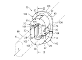
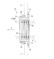
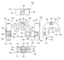
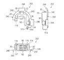
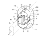
- FIG. 3 is a sectional view taken along line III-III in FIG. 2. It is detail drawing of the division member of the edge protector which concerns on 1st Embodiment. It is a perspective view of the edge protector which concerns on 2nd Embodiment.
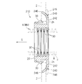
- FIG. 6 is a sectional view taken along line VI-VI in FIG. 5. It is detail drawing of the division member of the edge protector which concerns on 2nd Embodiment. It is a perspective view of the edge protector which concerns on a modification.
- the edge protector 10 is a member that protects the wire harness WH routed through the through hole 2h formed in the plate-like support 2 from the peripheral edge of the through hole 2h (see FIG. 3).
- the support 2 is, for example, a metal panel that constitutes the body of an automobile, and in a routing path or the like from the body to the door, a through hole 2h is formed to route the wire harness WH through the body. Yes.
- the peripheral edge portion of the through hole 2h has a shape in which a pair of arc-shaped portions are connected by a pair of linear portions.
- the wire harness WH to be protected by the edge protector 10 includes an electric wire 5 and a corrugated tube 6 that covers the periphery of the electric wire 5.
- the corrugated tube 6 is a protective tube for protecting the electric wire 5 from the outside. More specifically, the corrugated tube 6 is a member that is formed in a cylindrical shape and in which convex ridges 7 and concave ridges 8 along the circumferential direction are alternately continued in the axial direction.
- the corrugated tube 6 is manufactured by extruding a synthetic resin material such as polyamide (PA), polypropylene (PP), polybutylene terephthalate (PBT), ABS resin or polyethylene (PE), and blow molding or vacuum molding. It is an integrally molded member.
- the corrugated tube 6 may be formed of a relatively hard rubber (ethylene propylene diene rubber (EPDM), elastomer, or the like).
- corrugated tube 6 will be described as an example in which the corrugated tube 6 is formed in a cylindrical shape connecting a pair of arcuate portions with a pair of straight portions in a cross-sectional view orthogonal to the central axis.
- the edge protector 10 includes a pair of divided members 102 (see FIGS. 1, 2, and 4). In FIG. 3, the shape of the divided portion of the edge protector 10 is omitted.
- the pair of divided members 102 are members that form a cylindrical shape by being sandwiched and combined from both sides of the corrugated tube 6 of the wire harness WH.
- Each of the pair of divided members 102 includes a divided main body portion 20, a locking portion 30, a pressing portion 40, and a rib 50.
- the split main body portion 20 is a portion that forms a cylindrical shape through which the corrugated tube 6 is inserted while being inserted into the through hole 2h in the combined state of the pair of split members 102.
- the pair of divided main body portions 20 whose end portions are butted together in the combined state of the pair of divided members 102 will be described.
- the pair of divided main body portions 20 are inserted into the through hole 2h of the support body 2 from one side to the other side with the support body 2 interposed therebetween.
- this direction is described as the insertion direction S, and is also used to explain the direction of the edge protector 10 itself.
- the pair of divided main body portions 20 are interposed between the wire harness WH passed through the through hole 2h of the support 2 and the peripheral portion of the through hole 2h, and the wire harness WH is a through hole in the support 2. This prevents contact with the peripheral edge of 2h and damage (see FIG. 3).
- the outer peripheral portions of the pair of divided main body portions 20 have a shape corresponding to the peripheral edge portion of the through hole 2h and are set to a size slightly smaller than the through hole 2h.
- the inner peripheral portions of the pair of divided main body portions 20 have a shape corresponding to the outer shape of the outer peripheral portion of the peak portion 7 of the corrugated tube 6 and are set to a size slightly larger than the peak portion 7.
- the corresponding shape means a shape that is substantially similar and exists along the shape of the other party as a whole.
- the pair of divided main body portions 20 are formed in a cylindrical shape that connects the pair of arc-shaped portions 22 to the pair of linear portions 24 in a cross-sectional view orthogonal to the insertion direction S. But the division
- segmentation main-body part 20 should just be formed in the shape corresponding to the outer shape of the corrugated tube 6, and the shape of the peripheral part of the through-hole 2h, and is not restricted to the said shape.
- the latching portion 30 is a portion that latches from the front side in the insertion direction S with respect to the peripheral portion of the through hole 2 h in the support 2.
- the locking portion 30 extends from the outer peripheral portion (here, the end portion on the front side in the insertion direction S) of the main body portion 20 toward the outer peripheral side and the rear side in the insertion direction S, and the tip portion thereof is a free end. It is a shape part (see FIG. 3). That is, it is formed in a shape in which the protruding dimension toward the outer peripheral side gradually increases from the front side to the rear side in the insertion direction S.
- locking part 30 has a latching surface which faces the insertion direction S back at the front-end
- the locking part 30 projects from the outer peripheral part of the divided main body part 20 to the outer peripheral side, and the locking surface comes into contact with the peripheral part of the through hole 2h in the support 2 from the front side in the insertion direction S. From the form which stops, it is comprised so that elastic deformation can be carried out to the inner peripheral side rather than it.
- locking part 30 passes the through-hole 2h of the support body 2, it contacts with the peripheral part of the through-hole 2h, and is elastically deformed to the inner peripheral side until it fits in the through-hole 2h. Furthermore, the latching
- the locking portions 30 are respectively provided at four locations of the intermediate portions of the pair of arc-shaped portions 22 and the intermediate portions of the pair of linear portions 24 (see FIG. 2). .
- locking part 30 can be latched from the insertion direction S front side with sufficient balance in the circumferential direction with respect to the peripheral part of the through-hole 2h.
- the pressing portion 40 is formed in a shape protruding from the outer peripheral portion of the divided main body portion 20 to the outer peripheral side, and is a portion facing the peripheral portion of the through hole 2h of the support 2 from the rear side in the insertion direction S.
- the holding portion 40 is a portion that protrudes from the outer peripheral portion of the divided main body portion 20 to the outer peripheral side and forms an annular shape along the peripheral edge portion of the through hole 2 h of the support body 2 in the combined state of the pair of divided members 102.
- the presser portion 40 is formed in a flat shape along a surface orthogonal to the insertion direction S.
- the pressing portion 40 is formed in a size larger than the through hole 2h.
- the presser portion 40 is provided at an end portion in the insertion direction S in the divided main body portion 20 (see FIG. 3).
- the rib 50 is a portion that is formed in a protruding line that protrudes from the inner peripheral portion of the divided main body portion 20 toward the inner peripheral side along the circumferential direction.
- This rib 50 is a part which fits into the trough part 8 in the outer peripheral part of the corrugated tube 6 of the wire harness WH passed through the inside of the divided main body part 20 (see FIG. 3).
- a plurality of ribs 50 are provided at intervals at which the valley portions 8 of the corrugated tube 6 are provided.
- the protruding dimension of the rib 50 is set to a dimension that is the same as or smaller (smaller here) than the height difference between the peak 7 and the valley 8 of the corrugated tube 6.
- the width dimension of the rib 50 is set to a dimension that is the same as or smaller (smaller here) than the interval between the adjacent peaks 7 in the corrugated tube 6.
- the pair of split members 102 are formed in the same shape. Further, the split member 102 includes a short leg portion 104, a long leg portion 106 that is longer than the short leg portion 104 and includes the straight portion 24 of the split main body portion 20, and a curved portion 108 that includes the arcuate portion 22 of the split main body portion 20. It is formed in the shape which has (substantially J shape).
- the locking portion 30 is provided at a position corresponding to the intermediate portion of the pair of arc-shaped portions 22 and the intermediate portion of the pair of linear portions 24 in the circumferential direction of the divided main body portion 20.
- the division member 102 was provided in each intermediate
- the two locking portions 30 are manufactured integrally by injection molding or the like.
- the pair of split members 102 are provided with a lock mechanism that maintains a combined state.
- This locking mechanism is configured by an arm portion 114 provided at one end of the split member 102 and a receiving portion 116 that the arm portion 114 engages with the other end.
- the arm portion 114 is provided on the long leg portion 106
- the receiving portion 116 is provided on the short leg portion 104.
- the arm portion 114 has a protruding portion 115 that protrudes from one end portion of the dividing member 102 and protrudes from the tip end portion of the protruding piece toward the inner peripheral side of the dividing main body portion 20.
- the receiving portion 116 is formed in a concave shape that opens at the other end portion of the dividing member 102 and into which the arm portion 114 is inserted, and has a hole portion 117 into which the protruding portion 115 is fitted. That is, the hole 117 is formed in a shape that is recessed toward the inner peripheral side of the divided main body 20. Here, the hole 117 penetrates into the internal space of the divided main body 20.
- the projections 115 of the arm portions 114 of the one split member 102 are fitted into the holes 117 of the receiving portions 116 of the other split member 102, respectively.
- the united state of the split member 102 is maintained. More specifically, since the corrugated tube 6 is interposed between the pair of divided members 102 in a state where the projection 115 is fitted in the hole 117, the inner periphery of the divided member 102 in the receiving portion 116. The side portion is restricted from being deformed to the inner peripheral side.
- the movement of the arm portion 114 toward the outer peripheral side of the split member 102 is restricted when the portion of the arm portion 114 opposite to the protruding direction of the protruding portion 115 contacts the inner wall portion of the receiving portion 116. Thereby, the state which the arm part 114 latched to the receiving part 116 is maintained more reliably.
- the combination of the shapes of the arm part 114 and the receiving part 116 is preferable, but the protrusion 115 and the hole 117 protrude or dent on the outer peripheral side of the pair of split members 102. It may be formed in a shape.
- the locking portion 30 is provided at the end portion on the front side in the insertion direction S of the divided main body portion 20 and the holding portion 40 is provided at the end portion on the rear side in the insertion direction S of the divided main body portion 20
- the locking part 30 and the pressing part 40 may be provided in the middle part in the insertion direction S of the divided main body part 20.
- the edge protector 10 is constituted by a pair of divided members 102 that form a cylindrical shape by being sandwiched and combined from both sides of the corrugated tube 6.
- the pair of dividing members 102 are inserted into the through hole 2h of the support 2 and have a divided main body portion 20 that forms a cylindrical shape through which the corrugated tube 6 passes, and a divided main body with respect to the peripheral edge portion of the through hole 2h.
- the locking part 30 which locks from the insertion direction S front side of the part 20 and the pressing part 40 which opposes from the insertion direction S rear side with respect to the peripheral part of the through-hole 2h are provided. Thereby, the escape from the through-hole 2h is suppressed and attached to the support body 2.
- ribs 50 formed on the protruding ridges projecting from the inner peripheral portion of the divided main body portion 20 along the circumferential direction to the inner peripheral side are provided, and the ribs 50 are corrugated tube by the combined operation of the pair of divided members 102. 6, the edge protector 10 can be easily mounted while being positioned relative to the corrugated tube 6.
- both members can be formed with a single mold. Therefore, the equipment introduction cost accompanying the design and manufacture of the mold can be reduced. In addition, since one type of part is handled, it contributes to improvement in manageability and workability.
- the split main body 20 is formed in a cylindrical shape that connects the pair of arcuate portions 22 with the pair of linear portions 24 in a cross-sectional view orthogonal to the insertion direction S in the combined state of the pair of split members 102. Even if the locking portion 30 is provided so as to be positioned at an intermediate portion of the straight portion 24, the dividing member 102 has the long leg portion 106 including the short leg portion 104 and the straight portion 24, the short leg portion 104, and the long leg portion 106. Therefore, the pair of divided members 102 can be formed in the same shape.
- the pair of divided members 102 since the pair of divided members 102 has the arm portion 114 at one end portion and the receiving portion 116 to which the arm portion 114 is locked at the other end portion, the pair of divided members 102 are corrugated.
- the united state across the tube 6 can be maintained by itself.
- the arm portion 114 protrudes from one end portion of the dividing member 102 and has a protruding portion 115 protruding toward the inner peripheral side of the dividing main body portion 20, and the receiving portion 116 opens at the other end portion of the dividing member 102. And has a hole 117 into which the protruding portion 115 is fitted.
- the edge protector 210 according to the second embodiment will be described (see FIGS. 5 to 7).
- the edge protector 210 is different only in that the presser part 240 includes the split hook part 242 and the urging part 246.
- the reference numerals are attached and the description is omitted.
- the split collar portion 242 of the presser portion 240 is a portion formed in the same shape as the presser portion 40 according to the first embodiment, and faces the through hole 2h of the support body 2 from the rear side in the insertion direction S.
- the urging portion 246 is a portion that sandwiches the support 2 with the locking portion 30 in the insertion direction S (see FIGS. 5 and 6).
- the urging portion 246 is formed in a shape projecting from the split flange portion 242 to the outer peripheral side and the front side in the insertion direction S, and the tip end portion is a free end.
- the urging portion 246 protrudes from the outer peripheral portion of the split collar portion 242 and is formed in a shape that gradually tilts toward the front side in the insertion direction S toward the outer peripheral side. Accordingly, the biasing portion 246 is configured such that the tip side portion can be elastically deformed to the rear side in the insertion direction S from the above form.
- the urging portion 246 is formed in a shape in which the distal end portion is positioned at an interval smaller than the thickness dimension of the support 2 with respect to the locking surface (tip portion) of the locking portion 30 in the insertion direction S. And the urging
- the support body 2 is pressed against the surface on the rear side in the insertion direction S and elastically deforms rearward in the insertion direction S (see FIG. 6).
- biasing part 246 is the state which urged
- a plurality of urging portions 246 are provided at equal intervals in the circumferential direction of the split collar portion 242 (see FIG. 5).
- the urging portion 246 is provided at a position corresponding to the locking portion 30 in the circumferential direction of the divided collar portion 242. That is, the urging portion 246 is provided at a position corresponding to each intermediate portion of the pair of arcuate portions 22 and the pair of straight portions 24 of the divided main body portion 20 in the circumferential direction of the divided collar portion 242.
- the division member 202 respond
- the two locking portions 30 and the two biasing portions 246 provided at the positions are integrally formed by injection molding or the like (see FIG. 7).
- the urging portion is not limited to a shape that gradually inclines toward the front side in the insertion direction S toward the outer peripheral side, and is in surface contact with the surface on the rear side in the insertion direction S of the support body 2 at the tip end portion (outer peripheral side portion). It may have a flat portion, or may be formed in a cross-sectional mountain shape in which an intermediate portion between the proximal end portion and the distal end portion protrudes forward in the insertion direction S. Further, the configuration in which the urging portions 246 are provided at four locations has been described so far, but the configuration is not limited thereto. For example, the urging portion 246 is the center of the divided main body portion 20 in the combined state of the pair of dividing members 202. You may be provided in two places which oppose on both sides of an axis
- the shape of the presser part 340 having an urging part 346 that forms an annular shape that is continuous in the circumferential direction of the divided hook part 342 can also be adopted.
- the split hook part 342 of the presser part 340 has the same shape as the split hook part 242 of the presser part 240 described above.
- the urging portion 346 is formed in a shape in which the above-described urging portion 246 is continuous over the entire circumferential direction of the split collar portion 342.
- the divided member 302 is manufactured by integrally forming the divided main body portion 20, the presser portion 340, and the rib 50 divided into a substantially J shape by injection molding or the like. When this shape is adopted, rattling with respect to the support 2 can be more reliably suppressed.
- the presser portion 240 has a split collar portion 242 that forms a ring projecting from the outer peripheral portion of the split main body portion 20 to the outer peripheral side in the combined state of the pair of split members 202, and the split It has an urging portion 246 that protrudes from the position of the flange portion 242 toward the front side in the insertion direction S and is elastically deformable on the rear side in the insertion direction S. And since the support body 2 is pinched
- the amount of the material used is reduced with respect to the support body 2. Shaking can be suppressed.
- edge protector has been described in detail as described above, the above description is an example in all aspects, and the present invention is not limited thereto. It is understood that countless variations that are not illustrated can be envisaged without departing from the scope of the present invention.
Landscapes
- Engineering & Computer Science (AREA)
- Architecture (AREA)
- Civil Engineering (AREA)
- Structural Engineering (AREA)
- Mechanical Engineering (AREA)
- Details Of Indoor Wiring (AREA)
- Supports For Pipes And Cables (AREA)
- Installation Of Indoor Wiring (AREA)
Abstract
ワイヤーハーネスの保護具は、コルゲートチューブの両側から挟み込んで合体されることによって筒形状を形成する一対の分割部材により構成される。一対の分割部材は、支持体の貫通孔に挿入されると共にコルゲートチューブが内部に通される筒形状を形成する分割本体部と、分割本体部の外周部から外周側に張り出す形状に形成され、貫通孔の周縁部に対して挿入方向前方側から係止する形態から内周側へ弾性変形可能な係止部と、分割本体部の外周部から外周側に張り出す形状に形成され、貫通孔の周縁部に対して挿入方向後方側から対向する押え部と、分割本体部の内周部から周方向に沿って内周側に突起する凸条に形成され、コルゲートチューブに嵌合するリブとを備える。
Description
本発明は、貫通孔に通されるワイヤーハーネスの保護具に関する。
自動車等の車両に搭載されるワイヤーハーネスが、車両のボディを形成する金属パネル等に形成された貫通孔に通される場合、ワイヤーハーネスWHが貫通孔の開口縁部と接触して傷つくことを防ぐ必要がある。
特許文献1には、ワイヤーハーネスを内部に挿通させて、車両の金属パネルに形成された貫通穴の開口縁部に装着され、貫通穴の挿通部分におけるワイヤーハーネスの保護を図る樹脂インナー付きグロメットが開示されている。この樹脂インナー付きグロメットの樹脂インナーは、貫通穴に挿入される長円枠状の周壁と、該周壁の下端より突出した係止分割鍔部と、U字状に折り返しているロック片の外面にて突出して貫通穴の周縁に係止する係止爪とを有する部材である。
このような樹脂インナーは、貫通孔に通されるワイヤーハーネスを保護するエッジプロテクタとして単体で用いられることもある。
ところで、エッジプロテクタは、電線がコルゲートチューブに覆われて構成されたワイヤーハーネスを保護するために用いられることもある。この場合、コルゲートチューブがエッジプロテクタの内部に通される。
しかしながら、コルゲートチューブに対して凹凸による嵌合構造を採用して位置決めする場合、エッジプロテクタにコルゲートチューブを通すことが困難であった。
そこで、本発明は、ワイヤーハーネスの保護具を、コルゲートチューブに対して位置決めしつつ容易に装着することを目的とする。
第1の態様は、ワイヤーハーネスにおける電線を覆うコルゲートチューブが通される貫通孔が形成された支持体において、前記貫通孔の周縁部に取り付けられるワイヤーハーネスの保護具であって、前記コルゲートチューブの両側から挟み込んで合体されることによって筒形状を形成する一対の分割部材により構成され、前記一対の分割部材は、前記一対の分割部材の合体状態において前記支持体の前記貫通孔に挿入されると共に前記コルゲートチューブが内部に通される筒形状を形成する分割本体部と、前記分割本体部の外周部から外周側に張り出す形状に形成され、前記貫通孔の周縁部に対して前記分割本体部の挿入方向前方側から係止する形態から内周側へ弾性変形可能な係止部と、前記分割本体部の外周部から外周側に張り出す形状に形成され、前記貫通孔の周縁部に対して前記挿入方向後方側から対向する押え部と、前記分割本体部の内周部から周方向に沿って内周側に突起する凸条に形成され、前記分割本体部の内部に通される前記コルゲートチューブに嵌合する位置決め嵌合部とを備える。
第2の態様は、第1の態様に係るワイヤーハーネスの保護具であって、前記一対の分割部材は、同形状に形成されている。
第3の態様は、第2の態様に係るワイヤーハーネスの保護具であって、前記分割本体部は、前記一対の分割部材の合体状態において、前記挿入方向に直交する断面視において一対の弧状部を一対の直線部が結ぶ筒形状に形成され、前記係止部は、少なくとも前記直線部の中間部位に設けられ、前記分割部材は、短脚部と、前記短脚部より長く前記直線部を含む長脚部と、前記短脚部及び前記長脚部を結ぶ湾曲部とを有する形状に形成されている。
第4の態様は、第1~3の態様のいずれか一態様に係るワイヤーハーネスの保護具であって、前記一対の分割部材は、一方の端部に合体用係止部を有すると共に、他方の端部に前記合体用係止部が係止する合体用被係止部を有している。
第5の態様は、第4の態様に係るワイヤーハーネスの保護具であって、前記合体用係止部は、前記分割部材の前記一方の端部から突出し、前記分割本体部の内周側に突起する突起部を有し、前記合体用被係止部は、前記分割部材の前記他方の端部で開口して前記合体用係止部が挿入される凹状に形成され、内部に前記突起部が嵌り込む穴部を有している。
第6の態様は、第1~5の態様のいずれか一態様に係るワイヤーハーネスの保護具であって、前記押え部は、前記一対の分割部材の合体状態において、前記分割本体部の外周部から外周側に張り出す環状を形成する分割鍔部と、前記分割鍔部から前記挿入方向前方側且つ外周側に向けて張り出すと共に前記挿入方向後方側に弾性変形可能に形成され、前記挿入方向において前記係止部との間で前記支持体を挟む付勢部とを有している。
第7の態様は、第6の態様に係るワイヤーハーネスの保護具であって、前記付勢部は、前記一対の分割部材の合体状態において、前記分割鍔部の周方向において等間隔に複数設けられている。
第8の態様は、第6の態様に係るワイヤーハーネスの保護具であって、前記付勢部は、前記一対の分割部材の合体状態において、前記分割鍔部の周方向に連続する環状を形成する。
第1の態様に係るワイヤーハーネスの保護具によると、コルゲートチューブの両側から挟み込んで合体されることによって筒形状を形成する一対の分割部材により構成されている。一対の分割部材は、支持体の貫通孔に挿入されると共に内部にコルゲートチューブが通される筒形状を形成する分割本体部と、貫通孔の周縁部に対して分割本体部の挿入方向前方側から係止する係止部と、貫通孔の周縁部に対して分割本体部の挿入方向後方側から対向する押え部とを備えている。これにより、貫通孔からの抜け出しを抑制して支持体に取り付けられる。また、分割本体部の内周部から周方向に沿って内周側に突起する凸条に形成された位置決め嵌合部が備えられており、一対の分割部材の合体動作により位置決め嵌合部がコルゲートチューブに嵌合するため、ワイヤーハーネスの保護具を、コルゲートチューブに対して相互に位置決めしつつ容易に装着することができる。
第2の態様に係るワイヤーハーネスの保護具によると、一対の分割部材が同形状に形成されているため、一つの金型で両部材を形成することができる。
第3の態様に係るワイヤーハーネスの保護具によると、分割本体部が、一対の分割部材の合体状態において、挿入方向に直交する断面視において一対の弧状部を一対の直線部が結ぶ筒形状に形成されている場合に、係止部が直線部の中間部位に位置するように設けられても、分割部材が、短脚部と短脚部より長く直線部を含む長脚部と短脚部及び長脚部を結ぶ湾曲部とを有する形状に形成されているため、一対の分割部材を同形状に形成することができる。
第4の態様に係るワイヤーハーネス保護具によると、一対の分割部材が、一方の端部に合体用係止部を有すると共に、他方の端部に合体用係止部が係止する合体用被係止部を有しているため、一対の分割部材がコルゲートチューブを挟んで合体された状態を自身で維持することができる。
第5の態様に係るワイヤーハーネス保護具によると、合体用係止部が分割部材の一方の端部から突出し、分割本体部の内周側に突起する突起部を有し、合体用被係止部が分割部材の他方の端部で開口して合体用係止部が挿入される凹状に形成され、内部に突起部が嵌り込む穴部を有している。このため、一対の分割部材がコルゲートチューブを挟んで合体した状態において合体用係止部が合体用被係止部に係止すると、合体用被係止部の内周側にはコルゲートチューブが存在しており、突起部が嵌り込む穴部の周辺部分が内周側に変形することが抑制されることにより突起部が穴部から抜け出ることが抑制され、一対の分割部材の合体状態がより確実に維持される。
第6の態様に係るワイヤーハーネスの保護具によると、押え部が、一対の分割部材の合体状態において分割本体部の外周部から外周側に張り出す環状を形成する分割鍔部と、分割鍔部の位置から挿入方向前方側に向けて張り出すと共に挿入方向後方側に弾性変形可能に形成された付勢部とを有している。そして、挿入方向において付勢部及び係止部の間で支持体を挟むため、支持体に対するがたつきを抑制することができる。
第7の態様に係るワイヤーハーネスの保護具によると、付勢部が、一対の分割部材の合体状態において、分割鍔部の周方向において等間隔に複数設けられているため、材料の使用量を軽減しつつ支持体に対するがたつきを抑制することができる。
第8の態様に係るワイヤーハーネスの保護具によると、付勢部が、一対の分割部材の合体状態において分割鍔部の周方向に連続する環状を形成するため、より確実に支持体に対するがたつきを抑制することができる。
<第1実施形態>
以下、第1実施形態に係るエッジプロテクタ10の構成について説明する(図1~図4参照)。エッジプロテクタ10は、板状の支持体2に形成された貫通孔2hに通して配索されるワイヤーハーネスWHを、該貫通孔2hの周縁部から保護する部材である(図3参照)。
以下、第1実施形態に係るエッジプロテクタ10の構成について説明する(図1~図4参照)。エッジプロテクタ10は、板状の支持体2に形成された貫通孔2hに通して配索されるワイヤーハーネスWHを、該貫通孔2hの周縁部から保護する部材である(図3参照)。
支持体2は、例えば、自動車のボディを構成する金属パネルであり、ボディからドアに向かう配索経路等ではボディを貫通してワイヤーハーネスWHを配索するために、貫通孔2hが形成されている。ここでは、貫通孔2hの周縁部は、一対の弧状部を一対の直線部が結ぶ形状を成しているものとする。
本エッジプロテクタ10の保護対象となるワイヤーハーネスWHは、電線5とその電線5の周囲を覆うコルゲートチューブ6とを備えている。このコルゲートチューブ6は、電線5を外部から保護するための保護チューブである。より具体的には、コルゲートチューブ6は、筒形状に形成され、周方向に沿った凸条の山部7及び凹条の谷部8が軸方向に交互に連続した部材である。コルゲートチューブ6は、ポリアミド(PA)、ポリプロピレン(PP)、ポリブチレンテレフタレート(PBT)、ABS樹脂又はポリエチレン(PE)等の合成樹脂材料を押出成型すると共に、ブロー成型或いはバキューム成型して製造される一体成形部材である。他にも、コルゲートチューブ6は、比較的硬質なゴム(エチレンプロピレンジエンゴム(EPDM)、エラストマー等)により形成されることもある。
なお、ここでは、コルゲートチューブ6が、中心軸に直交する断面視において一対の弧状部を一対の直線部が結ぶ筒形状に形成されている例で説明する。
エッジプロテクタ10は、一対の分割部材102により構成されている(図1、図2、図4参照)。なお、図3においては、エッジプロテクタ10の分割箇所の形状を省略して示している。一対の分割部材102は、ワイヤーハーネスWHのコルゲートチューブ6の両側から挟み込んで合体されることによって筒形状を形成する部材である。ここでは、一対の分割部材102の合体状態について説明した後に、一対の分割部材102の個々の形状について説明する。一対の分割部材102は、それぞれ、分割本体部20と、係止部30と、押え部40と、リブ50とを備えている。
分割本体部20は、一対の分割部材102の合体状態において、貫通孔2hに挿入されると共にコルゲートチューブ6が内部に通される筒形状を形成する部分である。以下、一対の分割部材102の合体状態において、端部同士が突き合わされた一対の分割本体部20について説明する。一対の分割本体部20は、支持体2の貫通孔2hに対して、支持体2を挟んだ一方側から他方側に向けて挿入される。説明の便宜上、この方向を挿入方向Sとして説明し、エッジプロテクタ10自体の向きを説明するのにも利用する。そして、一対の分割本体部20は、支持体2の貫通孔2hに通されるワイヤーハーネスWHとその貫通孔2hの周縁部との間に介在して、ワイヤーハーネスWHが支持体2における貫通孔2hの周縁部と接触して傷つくことを防ぐ(図3参照)。
より具体的には、一対の分割本体部20の外周部は、貫通孔2hの周縁部に対応した形状で、且つ、該貫通孔2hより僅かに小さいサイズに設定されている。また、一対の分割本体部20の内周部は、コルゲートチューブ6の山部7の外周部の外形状に対応した形状で、且つ、該山部7より僅かに大きいサイズに設定されている。ここで、対応した形状とは、略相似形状であって、全体的に相手方の形状に沿って存在する形状をいう。ここでは、一対の分割本体部20は、挿入方向Sに直交する断面視において、一対の弧状部22を一対の直線部24が結ぶ筒状に形成されている。もっとも、分割本体部20は、コルゲートチューブ6の外形状及び貫通孔2hの周縁部の形状に対応した形状に形成されていればよく、上記形状に限られるものではない。
係止部30は、支持体2における貫通孔2hの周縁部に対して挿入方向S前方側から係止する部分である。この係止部30は、本体部20の外周部(ここでは、挿入方向S前方側の端部)から外周側且つ挿入方向S後方に向けて延び出て、その先端部が自由端とされた形状の部分である(図3参照)。すなわち、挿入方向S前方側から後方側に向けて徐々に外周側への突出寸法が大きくなる形状に形成されている。また、係止部30は、その先端部に挿入方向S後方を臨む係止面を有している。これにより、係止部30は、分割本体部20の外周部から外周側に張り出して、支持体2における貫通孔2hの周縁部に対して係止面が挿入方向S前方側から接触して係止する形態から、それよりも内周側へ弾性変形可能に構成されている。
そして、係止部30は、支持体2の貫通孔2hを通過する際に、その貫通孔2hの周縁部に接触しつつ、貫通孔2h内に収まる形態まで内周側に弾性変形する。さらに、係止部30は、貫通孔2hを通過後、弾性復帰する力によりもとの形態に戻って、貫通孔2hの周縁部に対して挿入方向S前方側から対向する。
ここでは、係止部30は、一対の分割本体部20において、一対の弧状部22の各中間部位及び一対の直線部24の各中間部位の4箇所にそれぞれ設けられている(図2参照)。これにより、各係止部30は、貫通孔2hの周縁部に対して、周方向においてバランスよく挿入方向S前方側から係止することができる。
押え部40は、分割本体部20の外周部から外周側に張り出す形状に形成され、支持体2の貫通孔2hの周縁部に対して挿入方向S後方側から対向する部分である。この押え部40は、一対の分割部材102の合体状態において、分割本体部20の外周部から外周側に張り出して支持体2の貫通孔2hの周縁部に沿う環状を形成する部分である。また、押え部40は、挿入方向Sに直交する面に沿って扁平な形状に形成されている。この押え部40は、貫通孔2hより大きいサイズに形成されている。ここでは、押え部40は、分割本体部20における挿入方向S後方の端部に設けられている(図3参照)。
リブ50は、分割本体部20の内周部から周方向に沿って内周側に突起する凸条に形成されている部分である。このリブ50は、分割本体部20の内部に通されるワイヤーハーネスWHのコルゲートチューブ6の外周部における谷部8に嵌り込む部分である(図3参照)。リブ50は、挿入方向Sにおいて、コルゲートチューブ6の谷部8が設けられている間隔で複数設けられている。また、リブ50の突出寸法は、コルゲートチューブ6の山部7と谷部8との高低差と同じかそれより小さい(ここでは小さい)寸法に設定される。また、リブ50の幅寸法は、コルゲートチューブ6における隣合う山部7同士の間隔と同じかそれより小さい(ここでは小さい)寸法に設定される。
そして、一対の分割部材102がコルゲートチューブ6の両側から合体される際に、一対の分割部材102の各々に設けられたリブ50が、コルゲートチューブ6の谷部8に嵌り込む。これにより、分割本体部20の内周部及びリブ50とコルゲートチューブ6とが、凹凸による嵌合構造により互いに位置決めされる。
ここでは、一対の分割部材102は、同形状に形成されている。さらに、分割部材102は、短脚部104と、該短脚部104より長く分割本体部20の直線部24を含む長脚部106と、分割本体部20の弧状部22を含む湾曲部108とを有する形状(略J字形状)に形成されている。
上述したように、係止部30は、分割本体部20の周方向において、一対の弧状部22の中間部位及び一対の直線部24の中間部位に対応する位置にそれぞれ設けられている。そして、分割部材102は、略J字形状に分割された分割本体部20、押え部40及びリブ50と、周方向において一方の弧状部22及び一方の直線部24の各中間部位に設けられた2つの係止部30とが射出成型等により一体形成されて製造される。
一対の分割部材102は、相互に合体された状態を維持するロック機構を備えている。ここでは、図4に示すロック機構の一例について説明する。このロック機構は、分割部材102の一方の端部に設けられたアーム部114と、他方の端部にアーム部114が係止する受け部116とにより構成されている。ここでは、アーム部114が長脚部106に設けられ、受け部116が短脚部104に設けられている。より具体的には、アーム部114は、分割部材102の一方の端部から突出し、突出片の先端部から分割本体部20の内周側に突起する突起部115を有している。また、受け部116は、分割部材102の他方の端部で開口してアーム部114が挿入される凹状に形成され、内部に突起部115が嵌り込む穴部117を有している。すなわち、穴部117は、分割本体部20の内周側に凹んだ形状に形成されている。ここでは、穴部117は、分割本体部20の内部空間内に貫通している。
そして、一対の分割部材102が合体されることにより、それぞれ、一方の分割部材102におけるアーム部114の突起部115が、他方の分割部材102における受け部116の穴部117に嵌り込み、一対の分割部材102の合体状態が維持される。より具体的には、突起部115が穴部117内に嵌り込んだ状態においては、一対の分割部材102の間にコルゲートチューブ6が介在しているため、受け部116における分割部材102の内周側の部分がそれより内周側に変形することを規制される。加えて、アーム部114における突起部115の突起方向とは反対側の部分が受け部116の内壁部と接触することにより、アーム部114の分割部材102の外周側への移動が規制される。これにより、アーム部114が受け部116に係止した状態がより確実に維持される。
なお、係止状態の維持の観点から言うと上記のアーム部114及び受け部116の形状の組み合わせが好ましいが、突起部115及び穴部117が一対の分割部材102の外周側に突起する或いは凹む形状に形成されていてもよい。
これまで、係止部30が分割本体部20の挿入方向S前方側の端部に設けられると共に、押え部40が分割本体部20の挿入方向S後方側の端部に設けられた構成について説明してきたが、係止部30及び押え部40は、分割本体部20の挿入方向Sの中途部に設けられてもよい。
第1実施形態に係るエッジプロテクタ10によると、コルゲートチューブ6の両側から挟み込んで合体されることによって筒形状を形成する一対の分割部材102により構成されている。一対の分割部材102は、支持体2の貫通孔2hに挿入されると共に内部にコルゲートチューブ6が通される筒形状を形成する分割本体部20と、貫通孔2hの周縁部に対して分割本体部20の挿入方向S前方側から係止する係止部30と、貫通孔2hの周縁部に対して挿入方向S後方側から対向する押え部40とを備えている。これにより、貫通孔2hからの抜け出しを抑制して支持体2に取り付けられる。また、分割本体部20の内周部から周方向に沿って内周側に突起する凸条に形成されたリブ50が備えられており、一対の分割部材102の合体動作によりリブ50がコルゲートチューブ6に嵌合するため、エッジプロテクタ10を、コルゲートチューブ6に対して相互に位置決めしつつ容易に装着することができる。
また、一対の分割部材102が同形状に形成されているため、一つの金型で両部材を形成することができる。これにより、金型の設計、製造に伴う設備導入費を軽減することができる。また、一種類の部品を扱うため、管理性、作業性の向上に寄与する。
また、分割本体部20が、一対の分割部材102の合体状態において、挿入方向Sに直交する断面視において一対の弧状部22を一対の直線部24が結ぶ筒形状に形成されている場合に、係止部30が直線部24の中間部位に位置するように設けられても、分割部材102が、短脚部104と直線部24を含む長脚部106と短脚部104及び長脚部106を結ぶ湾曲部108とを有する形状に形成されているため、一対の分割部材102を同形状に形成することができる。
また、一対の分割部材102が、一方の端部にアーム部114を有すると共に、他方の端部にアーム部114が係止する受け部116を有しているため、一対の分割部材102がコルゲートチューブ6を挟んで合体された状態を自身で維持することができる。
また、アーム部114が分割部材102の一方の端部から突出し、分割本体部20の内周側に突起する突起部115を有し、受け部116が分割部材102の他方の端部で開口してアーム部114が挿入される凹状に形成され、内部に突起部115が嵌り込む穴部117を有している。このため、一対の分割部材102がコルゲートチューブ6を挟んで合体した状態においてアーム部114が受け部116に係止すると、受け部116の内周側にはコルゲートチューブ6が存在しており、突起部115が嵌り込む穴部117の周辺部分が内周側に変形することが抑制されることにより突起部115が穴部117から抜け出ることが抑制され、一対の分割部材102の合体状態がより確実に維持される。
<第2実施形態>
次に、第2実施形態に係るエッジプロテクタ210について説明する(図5~図7参照)。エッジプロテクタ210は、第1実施形態に係るエッジプロテクタ10と比較して、押え部240が分割鍔部242と付勢部246とを有することのみが異なる構成であるため、同様の構成については同符号を付して説明を省略する。
次に、第2実施形態に係るエッジプロテクタ210について説明する(図5~図7参照)。エッジプロテクタ210は、第1実施形態に係るエッジプロテクタ10と比較して、押え部240が分割鍔部242と付勢部246とを有することのみが異なる構成であるため、同様の構成については同符号を付して説明を省略する。
押え部240の分割鍔部242は、第1実施形態に係る押え部40と同形状に形成されている部分であり、支持体2の貫通孔2hに対して挿入方向S後方側から対向する。
付勢部246は、挿入方向Sにおいて、係止部30との間で支持体2を挟む部分である(図5、図6参照)。この付勢部246は、分割鍔部242から外周側且つ挿入方向S前方側に張り出す形状に形成され、先端部が自由端となっている。ここでは、付勢部246は、分割鍔部242の外周部から突出し、外周側に向かうにつれて徐々に挿入方向S前方側に傾く形状に形成されている。これにより、付勢部246は、上記形態から、先端側の部分が挿入方向S後方側へ弾性変形可能に構成されている。
付勢部246は、挿入方向Sにおいて、先端部が係止部30の係止面(先端部)に対して支持体2の厚さ寸法より小さい間隔で位置する形状に形成されている。そして、付勢部246は、分割本体部20が支持体2の貫通孔2hに挿入されて係止部30が貫通孔2hの周縁部に対して挿入方向S前方側から係止した状態で、支持体2における挿入方向S後方側の面に押し付けられて挿入方向S後方側に弾性変形する(図6参照)。これにより、付勢部246は、支持体2を挿入方向S後方側から前方側に向けて付勢した状態になっている。すなわち、エッジプロテクタ10は、係止部30及び付勢部246の間で挟持力を作用させた状態で支持体2を挟んで、この支持体2に装着されている。
また、付勢部246は、分割鍔部242の周方向において等間隔に複数設けられている(図5参照)。ここでは、付勢部246は、分割鍔部242の周方向において係止部30に対応する位置に設けられている。すなわち、付勢部246は、分割鍔部242の周方向において、分割本体部20の一対の弧状部22及び一対の直線部24の各中間部位に対応する位置に設けられている。
そして、分割部材202は、略J字形状に分割された分割本体部20、分割鍔部242及びリブ50と、周方向において一方の弧状部22及び一方の直線部24の各中間部位に対応する位置に設けられた2つの係止部30及び2つの付勢部246とが射出成型等により一体形成されて製造される(図7参照)。
もっとも、付勢部は、外周側に向かうにつれて徐々に挿入方向S前方側に傾く形状に限られず、先端部(外周側の部位)に支持体2の挿入方向S後方側の面に面接触する平坦部分を有していてもよいし、基端部と先端部との中間部位が挿入方向S前方側に隆起した断面視山形状に形成されていてもよい。また、これまで付勢部246が4箇所に設けられる構成について説明してきたが、これに限られず、例えば、付勢部246は、一対の分割部材202の合体状態において、分割本体部20の中心軸を挟んで対向する2箇所に設けられていてもよい。
また、図8に示すエッジプロテクタ310のように、分割鍔部342の周方向に連続する環状を形成する付勢部346を有する押え部340の形状を採用することもできる。この押え部340の分割鍔部342は、上述した押え部240の分割鍔部242と同形状である。また、付勢部346は、上述した付勢部246が分割鍔部342の周方向全体に連続した形状に形成されている。そして、分割部材302は、略J字形状に分割された分割本体部20、押え部340及びリブ50が射出成型等により一体形成されて製造される。この形状を採用する場合、より確実に支持体2に対するがたつきを抑制することができる。
第2実施形態に係るエッジプロテクタ210によると、押え部240が、一対の分割部材202の合体状態において分割本体部20の外周部から外周側に張り出す環状を形成する分割鍔部242と、分割鍔部242の位置から挿入方向S前方側に向けて張り出すと共に挿入方向S後方側に弾性変形可能に形成された付勢部246とを有している。そして、挿入方向Sにおいて付勢部246及び係止部30の間で支持体2を挟むため、支持体2に対するがたつきを抑制することができる。
また、付勢部246が、一対の分割部材202の合体状態において、分割鍔部242の周方向において等間隔に複数設けられている形状によると、材料の使用量を軽減しつつ支持体2に対するがたつきを抑制することができる。
以上のようにこのエッジプロテクタは詳細に説明されたが、上記した説明は、全ての局面において例示であって、この発明がそれに限定されるものではない。例示されていない無数の変形例が、この発明の範囲から外れることなく想定され得るものと解される。
2 支持体
2h 貫通孔
5 電線
6 コルゲートチューブ
10、210、310 エッジプロテクタ
20 分割本体部
22 弧状部
24 直線部
30 係止部
40、240、340 押え部
242、342 分割鍔部
246、346 付勢部
50 リブ
102、202、302 分割部材
104 短脚部
106 長脚部
114 アーム部
115 突起部
116 受け部
117 穴部
S 挿入方向
WH ワイヤーハーネス
2h 貫通孔
5 電線
6 コルゲートチューブ
10、210、310 エッジプロテクタ
20 分割本体部
22 弧状部
24 直線部
30 係止部
40、240、340 押え部
242、342 分割鍔部
246、346 付勢部
50 リブ
102、202、302 分割部材
104 短脚部
106 長脚部
114 アーム部
115 突起部
116 受け部
117 穴部
S 挿入方向
WH ワイヤーハーネス
Claims (8)
- ワイヤーハーネスにおける電線を覆うコルゲートチューブが通される貫通孔が形成された支持体において、前記貫通孔の周縁部に取り付けられるワイヤーハーネスの保護具であって、
前記コルゲートチューブの両側から挟み込んで合体されることによって筒形状を形成する一対の分割部材により構成され、
前記一対の分割部材は、
前記一対の分割部材の合体状態において、前記支持体の前記貫通孔に挿入されると共に前記コルゲートチューブが内部に通される筒形状を形成する分割本体部と、
前記分割本体部の外周部から外周側に張り出す形状に形成され、前記貫通孔の周縁部に対して前記分割本体部の挿入方向前方側から係止する形態から内周側へ弾性変形可能な係止部と、
前記分割本体部の外周部から外周側に張り出す形状に形成され、前記貫通孔の周縁部に対して前記挿入方向後方側から対向する押え部と、
前記分割本体部の内周部から周方向に沿って内周側に突起する凸条に形成され、前記分割本体部の内部に通される前記コルゲートチューブに嵌合する位置決め嵌合部と、
を備える、ワイヤーハーネスの保護具。 - 請求項1に記載のワイヤーハーネスの保護具であって、
前記一対の分割部材は、同形状に形成されている、ワイヤーハーネスの保護具。 - 請求項2に記載のワイヤーハーネスの保護具であって、
前記分割本体部は、前記一対の分割部材の合体状態において、前記挿入方向に直交する断面視において一対の弧状部を一対の直線部が結ぶ筒形状に形成され、
前記係止部は、少なくとも前記直線部の中間部位に設けられ、
前記分割部材は、短脚部と、前記短脚部より長く前記直線部を含む長脚部と、前記短脚部及び前記長脚部を結ぶ湾曲部とを有する形状に形成されている、ワイヤーハーネスの保護具。 - 請求項1に記載のワイヤーハーネスの保護具であって、
前記一対の分割部材は、一方の端部に合体用係止部を有すると共に、他方の端部に前記合体用係止部が係止する合体用被係止部を有している、ワイヤーハーネスの保護具。 - 請求項4に記載のワイヤーハーネスの保護具であって、
前記合体用係止部は、前記分割部材の前記一方の端部から突出し、前記分割本体部の内周側に突起する突起部を有し、
前記合体用被係止部は、前記分割部材の前記他方の端部で開口して前記合体用係止部が挿入される凹状に形成され、内部に前記突起部が嵌り込む穴部を有している、ワイヤーハーネスの保護具。 - 請求項1に記載のワイヤーハーネスの保護具であって、
前記押え部は、
前記一対の分割部材の合体状態において、前記分割本体部の外周部から外周側に張り出す環状を形成する分割鍔部と、
前記分割鍔部から前記挿入方向前方側且つ外周側に向けて張り出すと共に前記挿入方向後方側に弾性変形可能に形成され、前記挿入方向において前記係止部との間で前記支持体を挟む付勢部と、
を有している、ワイヤーハーネスの保護具。 - 請求項6に記載のワイヤーハーネスの保護具であって、
前記付勢部は、前記一対の分割部材の合体状態において、前記分割鍔部の周方向において等間隔に複数設けられている、ワイヤーハーネスの保護具。 - 請求項6に記載のワイヤーハーネスの保護具であって、
前記付勢部は、前記一対の分割部材の合体状態において、前記分割鍔部の周方向に連続する環状を形成する、ワイヤーハーネスの保護具。
Applications Claiming Priority (2)
| Application Number | Priority Date | Filing Date | Title |
|---|---|---|---|
| JP2011060655A JP2012200037A (ja) | 2011-03-18 | 2011-03-18 | ワイヤーハーネスの保護具 |
| JP2011-060655 | 2011-03-18 |
Publications (1)
| Publication Number | Publication Date |
|---|---|
| WO2012127721A1 true WO2012127721A1 (ja) | 2012-09-27 |
Family
ID=46878911
Family Applications (1)
| Application Number | Title | Priority Date | Filing Date |
|---|---|---|---|
| PCT/JP2011/073496 Ceased WO2012127721A1 (ja) | 2011-03-18 | 2011-10-13 | ワイヤーハーネスの保護具 |
Country Status (2)
| Country | Link |
|---|---|
| JP (1) | JP2012200037A (ja) |
| WO (1) | WO2012127721A1 (ja) |
Cited By (1)
| Publication number | Priority date | Publication date | Assignee | Title |
|---|---|---|---|---|
| CN115483652A (zh) * | 2021-06-15 | 2022-12-16 | 住友电装株式会社 | 线束 |
Families Citing this family (3)
| Publication number | Priority date | Publication date | Assignee | Title |
|---|---|---|---|---|
| JP6078912B2 (ja) * | 2013-03-29 | 2017-02-15 | パナソニックIpマネジメント株式会社 | 設置構造 |
| JP6454110B2 (ja) * | 2014-09-12 | 2019-01-16 | ポップリベット・ファスナー株式会社 | 防振クランプ |
| JP2023010275A (ja) * | 2021-07-09 | 2023-01-20 | 矢崎総業株式会社 | 電線カバー |
Citations (4)
| Publication number | Priority date | Publication date | Assignee | Title |
|---|---|---|---|---|
| JPS6427918U (ja) * | 1987-08-10 | 1989-02-17 | ||
| JPH0160583U (ja) * | 1987-10-12 | 1989-04-17 | ||
| JPH0536720U (ja) * | 1991-10-18 | 1993-05-18 | 矢崎総業株式会社 | 2分割グロメツトインナ |
| JPH11155225A (ja) * | 1997-11-25 | 1999-06-08 | Sumitomo Wiring Syst Ltd | ワイヤーハーネス用取付具 |
-
2011
- 2011-03-18 JP JP2011060655A patent/JP2012200037A/ja not_active Withdrawn
- 2011-10-13 WO PCT/JP2011/073496 patent/WO2012127721A1/ja not_active Ceased
Patent Citations (4)
| Publication number | Priority date | Publication date | Assignee | Title |
|---|---|---|---|---|
| JPS6427918U (ja) * | 1987-08-10 | 1989-02-17 | ||
| JPH0160583U (ja) * | 1987-10-12 | 1989-04-17 | ||
| JPH0536720U (ja) * | 1991-10-18 | 1993-05-18 | 矢崎総業株式会社 | 2分割グロメツトインナ |
| JPH11155225A (ja) * | 1997-11-25 | 1999-06-08 | Sumitomo Wiring Syst Ltd | ワイヤーハーネス用取付具 |
Cited By (2)
| Publication number | Priority date | Publication date | Assignee | Title |
|---|---|---|---|---|
| CN115483652A (zh) * | 2021-06-15 | 2022-12-16 | 住友电装株式会社 | 线束 |
| JP2022191064A (ja) * | 2021-06-15 | 2022-12-27 | 住友電装株式会社 | ワイヤハーネス |
Also Published As
| Publication number | Publication date |
|---|---|
| JP2012200037A (ja) | 2012-10-18 |
Similar Documents
| Publication | Publication Date | Title |
|---|---|---|
| JP2010159843A (ja) | ボルト用クリップ | |
| JP4814947B2 (ja) | コルゲートチューブの接続部材 | |
| WO2013031260A1 (ja) | ハーネス保護具及びワイヤーハーネス配索構造部 | |
| JP6155246B2 (ja) | グロメット | |
| JP2007306776A (ja) | ワイヤハーネス用プロテクタ | |
| JP6401767B2 (ja) | 車体構造 | |
| CN109863658B (zh) | 线束模块 | |
| JP6970064B2 (ja) | グロメット | |
| JP6978389B2 (ja) | グロメット | |
| JP5758645B2 (ja) | グロメット | |
| JP6309298B2 (ja) | グロメットインナー及びワイヤーハーネス | |
| JP6752257B2 (ja) | インナー付きグロメット | |
| WO2012127721A1 (ja) | ワイヤーハーネスの保護具 | |
| CN108767538B (zh) | 索环 | |
| JP6752256B2 (ja) | インナー付きグロメット | |
| JP6329919B2 (ja) | 車両用内装部品 | |
| JP5761052B2 (ja) | グロメット | |
| JP2012175718A (ja) | グロメット | |
| CN117356004A (zh) | 护线套 | |
| JP2010283935A (ja) | ワイヤハーネスとプロテクタの取付構造 | |
| JP5765254B2 (ja) | グロメット | |
| JP5742573B2 (ja) | グロメット | |
| CN108749741B (zh) | 索环 | |
| JP2016025667A (ja) | グロメット及びグロメット付ワイヤーハーネス | |
| WO2012111179A1 (ja) | ワイヤハーネスの保護具 |
Legal Events
| Date | Code | Title | Description |
|---|---|---|---|
| 121 | Ep: the epo has been informed by wipo that ep was designated in this application |
Ref document number: 11861676 Country of ref document: EP Kind code of ref document: A1 |
|
| NENP | Non-entry into the national phase |
Ref country code: DE |
|
| 122 | Ep: pct application non-entry in european phase |
Ref document number: 11861676 Country of ref document: EP Kind code of ref document: A1 |