WO2012127679A1 - 車両の制御装置 - Google Patents
車両の制御装置 Download PDFInfo
- Publication number
- WO2012127679A1 WO2012127679A1 PCT/JP2011/057154 JP2011057154W WO2012127679A1 WO 2012127679 A1 WO2012127679 A1 WO 2012127679A1 JP 2011057154 W JP2011057154 W JP 2011057154W WO 2012127679 A1 WO2012127679 A1 WO 2012127679A1
- Authority
- WO
- WIPO (PCT)
- Prior art keywords
- operating point
- engine operating
- engine
- vehicle
- power
- Prior art date
- Legal status (The legal status is an assumption and is not a legal conclusion. Google has not performed a legal analysis and makes no representation as to the accuracy of the status listed.)
- Ceased
Links
Images






Classifications
-
- B—PERFORMING OPERATIONS; TRANSPORTING
- B60—VEHICLES IN GENERAL
- B60W—CONJOINT CONTROL OF VEHICLE SUB-UNITS OF DIFFERENT TYPE OR DIFFERENT FUNCTION; CONTROL SYSTEMS SPECIALLY ADAPTED FOR HYBRID VEHICLES; ROAD VEHICLE DRIVE CONTROL SYSTEMS FOR PURPOSES NOT RELATED TO THE CONTROL OF A PARTICULAR SUB-UNIT
- B60W20/00—Control systems specially adapted for hybrid vehicles
- B60W20/10—Controlling the power contribution of each of the prime movers to meet required power demand
- B60W20/15—Control strategies specially adapted for achieving a particular effect
-
- B—PERFORMING OPERATIONS; TRANSPORTING
- B60—VEHICLES IN GENERAL
- B60K—ARRANGEMENT OR MOUNTING OF PROPULSION UNITS OR OF TRANSMISSIONS IN VEHICLES; ARRANGEMENT OR MOUNTING OF PLURAL DIVERSE PRIME-MOVERS IN VEHICLES; AUXILIARY DRIVES FOR VEHICLES; INSTRUMENTATION OR DASHBOARDS FOR VEHICLES; ARRANGEMENTS IN CONNECTION WITH COOLING, AIR INTAKE, GAS EXHAUST OR FUEL SUPPLY OF PROPULSION UNITS IN VEHICLES
- B60K6/00—Arrangement or mounting of plural diverse prime-movers for mutual or common propulsion, e.g. hybrid propulsion systems comprising electric motors and internal combustion engines
- B60K6/20—Arrangement or mounting of plural diverse prime-movers for mutual or common propulsion, e.g. hybrid propulsion systems comprising electric motors and internal combustion engines the prime-movers consisting of electric motors and internal combustion engines, e.g. HEVs
- B60K6/42—Arrangement or mounting of plural diverse prime-movers for mutual or common propulsion, e.g. hybrid propulsion systems comprising electric motors and internal combustion engines the prime-movers consisting of electric motors and internal combustion engines, e.g. HEVs characterised by the architecture of the hybrid electric vehicle
- B60K6/44—Series-parallel type
- B60K6/445—Differential gearing distribution type
-
- B—PERFORMING OPERATIONS; TRANSPORTING
- B60—VEHICLES IN GENERAL
- B60W—CONJOINT CONTROL OF VEHICLE SUB-UNITS OF DIFFERENT TYPE OR DIFFERENT FUNCTION; CONTROL SYSTEMS SPECIALLY ADAPTED FOR HYBRID VEHICLES; ROAD VEHICLE DRIVE CONTROL SYSTEMS FOR PURPOSES NOT RELATED TO THE CONTROL OF A PARTICULAR SUB-UNIT
- B60W10/00—Conjoint control of vehicle sub-units of different type or different function
- B60W10/04—Conjoint control of vehicle sub-units of different type or different function including control of propulsion units
- B60W10/06—Conjoint control of vehicle sub-units of different type or different function including control of propulsion units including control of combustion engines
-
- B—PERFORMING OPERATIONS; TRANSPORTING
- B60—VEHICLES IN GENERAL
- B60W—CONJOINT CONTROL OF VEHICLE SUB-UNITS OF DIFFERENT TYPE OR DIFFERENT FUNCTION; CONTROL SYSTEMS SPECIALLY ADAPTED FOR HYBRID VEHICLES; ROAD VEHICLE DRIVE CONTROL SYSTEMS FOR PURPOSES NOT RELATED TO THE CONTROL OF A PARTICULAR SUB-UNIT
- B60W10/00—Conjoint control of vehicle sub-units of different type or different function
- B60W10/04—Conjoint control of vehicle sub-units of different type or different function including control of propulsion units
- B60W10/08—Conjoint control of vehicle sub-units of different type or different function including control of propulsion units including control of electric propulsion units, e.g. motors or generators
-
- B—PERFORMING OPERATIONS; TRANSPORTING
- B60—VEHICLES IN GENERAL
- B60W—CONJOINT CONTROL OF VEHICLE SUB-UNITS OF DIFFERENT TYPE OR DIFFERENT FUNCTION; CONTROL SYSTEMS SPECIALLY ADAPTED FOR HYBRID VEHICLES; ROAD VEHICLE DRIVE CONTROL SYSTEMS FOR PURPOSES NOT RELATED TO THE CONTROL OF A PARTICULAR SUB-UNIT
- B60W20/00—Control systems specially adapted for hybrid vehicles
- B60W20/10—Controlling the power contribution of each of the prime movers to meet required power demand
-
- B—PERFORMING OPERATIONS; TRANSPORTING
- B60—VEHICLES IN GENERAL
- B60W—CONJOINT CONTROL OF VEHICLE SUB-UNITS OF DIFFERENT TYPE OR DIFFERENT FUNCTION; CONTROL SYSTEMS SPECIALLY ADAPTED FOR HYBRID VEHICLES; ROAD VEHICLE DRIVE CONTROL SYSTEMS FOR PURPOSES NOT RELATED TO THE CONTROL OF A PARTICULAR SUB-UNIT
- B60W30/00—Purposes of road vehicle drive control systems not related to the control of a particular sub-unit, e.g. of systems using conjoint control of vehicle sub-units
- B60W30/18—Propelling the vehicle
- B60W30/188—Controlling power parameters of the driveline, e.g. determining the required power
- B60W30/1882—Controlling power parameters of the driveline, e.g. determining the required power characterised by the working point of the engine, e.g. by using engine output chart
-
- B—PERFORMING OPERATIONS; TRANSPORTING
- B60—VEHICLES IN GENERAL
- B60W—CONJOINT CONTROL OF VEHICLE SUB-UNITS OF DIFFERENT TYPE OR DIFFERENT FUNCTION; CONTROL SYSTEMS SPECIALLY ADAPTED FOR HYBRID VEHICLES; ROAD VEHICLE DRIVE CONTROL SYSTEMS FOR PURPOSES NOT RELATED TO THE CONTROL OF A PARTICULAR SUB-UNIT
- B60W2556/00—Input parameters relating to data
-
- Y—GENERAL TAGGING OF NEW TECHNOLOGICAL DEVELOPMENTS; GENERAL TAGGING OF CROSS-SECTIONAL TECHNOLOGIES SPANNING OVER SEVERAL SECTIONS OF THE IPC; TECHNICAL SUBJECTS COVERED BY FORMER USPC CROSS-REFERENCE ART COLLECTIONS [XRACs] AND DIGESTS
- Y02—TECHNOLOGIES OR APPLICATIONS FOR MITIGATION OR ADAPTATION AGAINST CLIMATE CHANGE
- Y02T—CLIMATE CHANGE MITIGATION TECHNOLOGIES RELATED TO TRANSPORTATION
- Y02T10/00—Road transport of goods or passengers
- Y02T10/60—Other road transportation technologies with climate change mitigation effect
- Y02T10/62—Hybrid vehicles
-
- Y—GENERAL TAGGING OF NEW TECHNOLOGICAL DEVELOPMENTS; GENERAL TAGGING OF CROSS-SECTIONAL TECHNOLOGIES SPANNING OVER SEVERAL SECTIONS OF THE IPC; TECHNICAL SUBJECTS COVERED BY FORMER USPC CROSS-REFERENCE ART COLLECTIONS [XRACs] AND DIGESTS
- Y10—TECHNICAL SUBJECTS COVERED BY FORMER USPC
- Y10S—TECHNICAL SUBJECTS COVERED BY FORMER USPC CROSS-REFERENCE ART COLLECTIONS [XRACs] AND DIGESTS
- Y10S903/00—Hybrid electric vehicles, HEVS
- Y10S903/902—Prime movers comprising electrical and internal combustion motors
- Y10S903/903—Prime movers comprising electrical and internal combustion motors having energy storing means, e.g. battery, capacitor
- Y10S903/93—Conjoint control of different elements
Definitions
- the present invention relates to control of a vehicle including an engine having an exhaust gas recirculation (Exhaust Gas Recirculation) device and a motor connected to the engine.
- exhaust gas recirculation Exhaust Gas Recirculation
- Some recent engines include an exhaust gas recirculation device (hereinafter also referred to as an “EGR device”) that recirculates a part of the exhaust gas to the intake passage for the purpose of improving fuel consumption.
- EGR device exhaust gas recirculation device
- Patent Document 1 in a vehicle in which the traveling state is controlled by the output of a direct injection engine having an EGR device, the engine operation is reduced when the engine output needs to be reduced.
- Patent Document 1 A technique for suppressing exhaust gas recirculation when the state is a predetermined state is disclosed.
- Patent Document 1 does not specifically examine how to control the EGR device in a vehicle (so-called hybrid vehicle) including an engine and motor having the EGR device.
- the present invention has been made to solve the above-described problems, and an object thereof is to improve the fuel consumption of a vehicle including an engine and a motor having an EGR device.
- the control device controls a vehicle including an engine including a recirculation device for returning a part of exhaust gas to the intake passage and a motor that generates vehicle driving force together with the engine.
- the recirculation device is activated when the engine is operated in the recirculation region and is stopped when the engine is operated in the non-recirculation region where the torque is lower than the recirculation region.
- the control device includes a calculation unit that calculates a vehicle required power required for the vehicle, and a control unit that controls the engine and the motor so that the engine is operated in the recirculation region while satisfying the vehicle required power.
- the engine has an injection valve that directly injects fuel into the cylinder.
- the control unit controls the actual engine operating point so that the actual engine operating point determined by the actual engine speed and the actual torque is included in the recirculation region.
- the control unit calculates a requested engine operating point based on the vehicle requested power, and when the requested engine operating point is included in the recirculation region, the requested engine operating point is set as an actual engine operating point, and the requested engine operating point is When not included in the recirculation region, the corrected engine operation point that is moved to the high torque side so that the requested engine operation point is included in the recirculation region is set as the actual engine operation point.
- the corrected engine operating point has a lower rotational speed, higher torque, and the same power than the required engine operating point.
- the corrected engine operating point has the same rotational speed and higher power than the requested engine operating point.
- the corrected engine operating point has a lower rotational speed, higher torque, and higher power than the required engine operating point.
- the control unit increases the power of the motor according to the increase in the power at the corrected engine operating point so as to satisfy the vehicle required power. Reduce.
- the fuel consumption of a vehicle including an engine and a motor having an EGR device can be improved.
- FIG. 1 shows the structure of a vehicle. It is the figure which showed the structure of the engine typically. It is a functional block diagram of ECU.
- FIG. 3 is a diagram (part 1) illustrating a method for setting a command engine operating point OPcom. It is a figure (the 1) which shows a control mode of an engine, 1st MG, and 2M. It is a flowchart which shows the process sequence of ECU.
- FIG. 6 is a diagram (part 2) illustrating a method for setting a command engine operating point OPcom.
- FIG. 10 is a diagram (No.
- FIG. 10 is a diagram (No. 4) illustrating a method for setting a command engine operating point OPcom; It is a figure (the 2) which shows the structure of a vehicle.
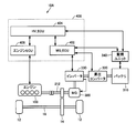
- FIG. 1 is a diagram showing a structure of a vehicle 10 on which a control device according to this embodiment is mounted.
- Vehicle 10 is a hybrid vehicle that travels using at least one of engine 100 and second motor generator (hereinafter referred to as “second MG”) 300B.
- second MG second motor generator
- Vehicle 10 includes, in addition to engine 100 and second MG 300B described above, first motor generator (hereinafter referred to as “first MG”) 300A, power split device 200, drive wheel 12, reducer 14, battery 310, boost converter 320, inverter 330, engine ECU 406, MG_ECU 402, HV_ECU 404, and the like.
- first MG first motor generator
- the power split device 200 includes a planetary gear including a sun gear, a pinion gear, a carrier, and a ring gear.
- the pinion gear engages with the sun gear and the ring gear.
- the carrier supports the pinion gear so as to be capable of rotating, and is connected to the crankshaft of engine 100.
- the sun gear is coupled to the rotation shaft of first MG 300A.
- the ring gear is connected to the rotation shaft of second MG 300 ⁇ / b> B and speed reducer 14 via output shaft 212.
- the engine 100, the first MG 300A, and the second MG 300B are connected via the power split device 200 including the planetary gears, so that the engine rotational speed Ne, the first MG rotational speed Nm1, and the second MG rotational speed Nm2 are shared.
- the relationship is a straight line (see FIG. 5 described later).
- Reduction gear 14 transmits power generated by engine 100, first MG 300A, and second MG 300B to drive wheels 12, and transmits driving wheel 12 to engine 100, first MG 300A, and second MG 300B.
- Battery 310 stores electric power for driving first MG 300A and second MG 300B.
- Boost converter 320 performs voltage conversion between battery 310 and inverter 330.
- Inverter 330 performs current control while converting the direct current of battery 310 and the alternating current of first MG 300A and second MG 300B.
- Engine ECU 406 controls the operating state of engine 100.
- MG_ECU 402 controls the charge / discharge states of first MG 300 ⁇ / b> A, second MG 300 ⁇ / b> B, inverter 330, and battery 310 according to the state of vehicle 10.
- the HV_ECU 404 controls and controls the engine ECU 406, the MG_ECU 402, and the like so that the vehicle 10 can operate most efficiently.
- each ECU is separately configured, but may be configured as an ECU in which two or more ECUs are integrated.
- an example is an ECU 400 in which MG_ECU 402, HV_ECU 404, and engine ECU 406 are integrated.
- MG_ECU 402, HV_ECU 404, and engine ECU 406 are described as ECU 400 without being distinguished from each other.
- ECU 400 includes a vehicle speed sensor, an accelerator opening sensor, a throttle opening sensor, an engine rotation speed sensor, a first MG rotation speed sensor, a second MG rotation speed sensor (all not shown), and a monitoring unit that monitors the state of battery 310.
- a signal from 340 or the like is input.
- FIG. 2 is a diagram schematically showing the configuration of the engine 100.
- the engine 100 includes an engine main body 110, an intake pipe 120, an intake manifold with surge tank 130, a delivery chamber 140, an exhaust manifold 150, an exhaust pipe 160, and an EGR pipe 170.
- the engine main body 110 includes a plurality of cylinders 111 (four cylinders in FIG. 1), a plurality of intake ports 112, a plurality of exhaust ports 113, and a plurality of in-cylinder injectors 114 respectively provided corresponding to the plurality of cylinders 111.
- air drawn from an air cleaner flows through intake pipe 120 (see arrow A) and is introduced into surge tank 131 in intake manifold with surge tank 130.
- An electronic throttle valve 121 controlled by a control signal from the ECU 400 is provided in the vicinity of the connection portion with the surge tank 131 in the intake pipe 120. The amount of air introduced into the surge tank 131 is adjusted according to the operation amount (throttle opening) of the electronic throttle valve 121.
- the intake manifold with surge tank 130 is provided between the intake pipe 120 and the engine body 110.
- the intake manifold with surge tank 130 is one in which a surge tank 131 and an intake manifold 132 are provided integrally.
- the surge tank 131 and the intake manifold 132 may be provided separately. Air in the surge tank 131 is distributed to each intake port 112 of the engine body 110 via the intake manifold 132 (see arrows A1 to A4). Air distributed to each intake port 112 is introduced into each cylinder 111.
- Each cylinder injector 114 directly injects fuel into each cylinder 111. That is, the engine 100 is a so-called cylinder injection engine.
- the fuel injected into each cylinder 111 is mixed with air and ignited and burned by an ignition device (not shown).
- Exhaust gas after combustion is discharged to each exhaust port 113.
- the exhaust gas discharged to the exhaust port 113 is collected by the exhaust manifold 150 and sent to the exhaust pipe 160 (see arrows B and B1 to B4).
- the engine 100 is equipped with an exhaust gas recirculation (hereinafter also referred to as “EGR”) device that recirculates a part of the exhaust gas to the intake flow path.
- EGR exhaust gas recirculation
- the EGR device includes an EGR pipe 170 and an EGR valve 180. A part of the exhaust is returned to the intake side via the EGR pipe 170 and the delivery chamber 140 (see arrows C1, C21 to C24).
- the EGR pipe 170 is provided with an EGR valve 180 that is controlled by a control signal from the ECU 400.
- the vehicle 10 is a hybrid vehicle having a power train structure including the in-cylinder injection type engine 100 having the EGR device and the second MG 300 ⁇ / b> B that generates a vehicle driving force together with the engine 100.
- the EGR device is operated only in a region where the load required for the vehicle is high from the viewpoint of deposit prevention of the in-cylinder injector 114. That is, the injection hole of the in-cylinder injector 114 exists in the cylinder, and deposits accumulate on the injection hole depending on the combustion state of the fuel.
- the load required for the vehicle is high, the engine load increases and the fuel injection amount from the injection hole Therefore, it is possible to blow away the deposit near the nozzle hole by fuel injection.
- the engine load is also low and the amount of fuel injection from the injection port is reduced, so that it is difficult to blow off deposits near the injection port by fuel injection.
- the EGR device is operated and the exhaust gas is recirculated in such a low engine load, unburned hydrocarbons contained in the exhaust gas will become tar in the cylinder, causing further deposition of deposits. Become. Therefore, the EGR device is operated only in a region where the engine load is high, and is stopped in a region where the engine load is low (hereinafter, the high load region where the EGR device is operated is referred to as “EGR region”, and the EGR device is stopped.
- the low load area is called “non-EGR area”). Therefore, when engine 100 is operated in a non-EGR region, the effect of improving fuel efficiency by EGR cannot be obtained.
- the ECU 400 controls the engine 100, the first MG 300A, and the second MG 300B so that the engine 100 is operated in the EGR region while satisfying the vehicle required power. This is the most characteristic point of the present invention.
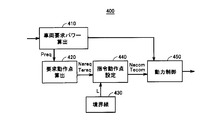
- FIG. 3 is a functional block diagram of ECU 400. Each functional block shown in FIG. 3 may be realized by hardware or software.
- ECU 400 includes a vehicle required power calculation unit 410, a required operation point calculation unit 420, a boundary line storage unit 430, a command operation point setting unit 440, and a power control unit 450.
- the vehicle required power calculation unit 410 calculates the vehicle required power Preq based on the user's accelerator pedal operation amount and the like.
- the required operating point calculation unit 420 calculates a required engine operating point OPreq based on the vehicle required power Preq.
- the engine operating point is an index indicating the operating state of the engine 100 determined by the engine speed Ne and the engine torque Te.
- the required engine operating point OPreq is an engine operating point that satisfies the vehicle required power Preq. Therefore, calculating the required engine operating point OPreq is actually calculating the required engine rotation speed Nereq and the required engine torque Tereq.
- the boundary line storage unit 430 stores a boundary line L between the EGR area and the non-EGR area.
- the command operating point setting unit 440 sets the command engine operating point OPcom (command engine rotational speed Necom, command engine torque Tecom) based on the requested engine operating point OPreq and the boundary line L. Specifically, when requested engine operating point OPreq exceeds boundary line L and is included in the EGR region, command operating point setting unit 440 sets requested engine operating point OPreq as command engine operating point OPcom as it is.
- command engine operating point OPcom command engine rotational speed Necom, command engine torque Tecom
- the command operating point setting unit 440 corrects the requested engine operating point OPreq to be included in the EGR region, and The engine operating point is set to the command engine operating point OPcom.
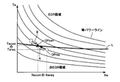
- FIG. 4 is a diagram schematically showing a method for setting the command engine operating point OPcom (a method for correcting the requested engine operating point OPreq).
- the command operating point setting unit 440 sets the requested engine operating point OPreq to the boundary line L on the same power line as the requested engine operating point OPreq.
- the engine operating point after the movement is set to the command engine operating point OPcom. That is, as shown in FIG. 4, the command operating point setting unit 440 sets the rotational speed obtained by reducing the required engine rotational speed Nereq by the predetermined rotational speed ⁇ to the command engine rotational speed Necom, and sets the required engine torque Tereq to the predetermined torque.
- the torque increased by ⁇ is set as the command engine torque Tecom.
- the power control unit 450 controls the engine 100, the first MG 300A, and the second MG 300B so that the actual engine operating point matches the command engine operating point OPcom while satisfying the vehicle required power.
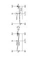
- FIG. 5 is a diagram schematically showing the control modes of the engine 100, the first MG 300A, and the second MG 300B on a nomographic chart.
- “Tg” represents the first MG torque
- “Tm” represents the second MG torque
- “Tep” represents torque transmitted from the engine 100 to the output shaft 212 via the power split device 200 (hereinafter, “Engine direct torque”).
- the command engine operating point OPcom is set such that Tecom> Tereq and Necom ⁇ Nereq (see the white arrow in FIG. 5).
- FIG. 6 is a flowchart showing a processing procedure of the ECU 400 for realizing the above-described functions.
- step (hereinafter, step is abbreviated as “S”) 10 ECU 400 calculates required engine operating point OPreq (that is, required engine rotation speed Nereq and required engine torque Tereq) based on vehicle required power Preq.
- required engine operating point OPreq that is, required engine rotation speed Nereq and required engine torque Tereq
- ECU 400 determines whether or not requested engine operating point OPreq is included in the EGR region (whether or not boundary line L is exceeded).
- ECU 400 moves the process to S13 and moves requested engine operating point OPreq to the high torque side so as to be included in the EGR region.
- ECU 400 outputs, to engine 100, first MG 300A, and second MG 300B, a command for matching the actual engine operating point to commanded engine operating point OPcom while satisfying the vehicle required power.
- ECU 400 operates the EGR device.
- the ECU 400 when the vehicle required power is low in a vehicle including an in-cylinder injection engine having an EGR device and a motor (when the required engine operating point is included in the non-EGR region). Even so, the engine and the motor are controlled so as to maintain the operation of the EGR device while satisfying the vehicle required power. Therefore, fuel consumption can be improved while responding to user requests.
- FIG. 7 is a diagram schematically showing a method for setting the command engine operating point OPcom (a method for correcting the required engine operating point OPreq) according to this modification.
- the required engine operating point OPreq when the required engine operating point OPreq is included in the non-EGR region, the required engine operating point OPreq is moved into the EGR region with equal power (see arrow A in FIG. 7), The engine operating point after the movement may be set as the command engine operating point OPcom by moving to an operating point where power transmission and thermal efficiency are optimal in the EGR region using a map that takes into account thermal efficiency (see arrow B in FIG. 7). . By doing so, power transmission and thermal efficiency can be optimized while maintaining the operation of the EGR device.
- the command engine operating point OPcom has a lower engine speed, a higher torque, and the same power as compared to the required engine operating point OPreq (see FIG. 4).
- the command engine operating point OPcom may be set so that the engine speed is the same and the torque is higher (that is, the power is higher) than the required engine operating point OPreq.
- FIG. 8 is a diagram schematically showing a method for setting the command engine operating point OPcom (a method for correcting the required engine operating point OPreq) according to this modification.
- the requested engine operating point OPreq when the requested engine operating point OPreq is included in the non-EGR region, the requested engine operating point OPreq is moved to an operating point that is higher in power than the requested engine operating point OPreq and included in the EGR region.
- the later engine operating point may be set as the command engine operating point OPcom.
- the command engine rotational speed Necom is kept at the requested engine rotational speed Nereq. In this case, since it is not necessary to change the engine rotation speed, for example, even when the actual engine operating point is included in the non-EGR region, the actual engine operating point can be moved to the EGR region early.
- FIG. 9 is a diagram schematically showing the control modes of the engine 100, the first MG 300A, and the second MG 300B according to the present modification on a collinear diagram.
- the power transmitted from engine 100 to output shaft 212 via power split device 200 hereinafter referred to as “engine direct power” also increases. Therefore, ECU 400 reduces second MG torque Tm by an amount corresponding to the increase amount of engine direct power. In this way, it is possible to satisfy the required vehicle power without changing the vehicle power as a whole while maintaining the operation of the EGR device.
- the command engine operating point OPcom is set in consideration of the optimum operating point, and in the second modified example, the power of the command engine operating point OPcom is increased from the power of the required engine operating point OPreq.
- the powers of the command engine operating point OPcom may be increased more than the power of the requested engine operating point OPreq while considering the optimal operating point by combining the first and second modifications.
- FIG. 10 is a diagram schematically showing a method for setting the command engine operating point OPcom (a method for correcting the required engine operating point OPreq) according to this modification.
- the requested engine operating point OPreq is included in the non-EGR region
- the requested engine operating point OPreq is moved to an operating point that is higher in power than the requested engine operating point OPreq and included in the EGR region (FIG. 10). 10) (see arrow C in FIG. 10), and further move to an operating point where power transmission and thermal efficiency are optimal in the EGR region using a map that takes into account power transmission and thermal efficiency (see arrow D in FIG. 10).
- the engine operating point may be the command engine operating point OPcom. Even in this way, as in the first modification, the power transmission and the thermal efficiency can be optimized while maintaining the operation of the EGR device.
- the power at the command engine operating point OPcom increases more than the power at the requested engine operating point OPreq as in the second modification. Therefore, as described with reference to FIG. 9 described above, the second MG torque Tm may be decreased by an amount corresponding to the increase amount of the engine direct power.
- the engine to which the present invention is applicable may be an engine having an EGR device (particularly, an in-cylinder injection type engine). It is not limited to the engine 100 shown.
- the vehicle to which the present invention can be applied is not limited to the vehicle 10 shown in FIG. 1 as long as it is a hybrid vehicle including an engine having an EGR device and a motor.
- a vehicle 10 ⁇ / b> A including an in-cylinder injection engine 100 having an EGR device and one motor generator 300 may be used.
- the adjustment of the engine load factor can be absorbed by the motor generator 300, so that the degree of freedom of control of the engine operating point or the engine load factor is larger so as to maintain the EGR region, and thus the present invention can be more easily performed. Applicable.
- 10, 10A vehicle, 12 drive wheels, 14 reducer 100 engine, 110 engine body, 111 cylinder, 112 intake port, 113 exhaust port, 114 in-cylinder injector, 120 intake pipe, 121 electronic throttle valve, 130 intake with surge tank Manifold, 131 surge tank, 132 intake manifold, 140 delivery chamber, 150 exhaust manifold, 160 exhaust pipe, 170 EGR pipe, 180 EGR valve, 200 power split device, 212 output shaft, 300 motor generator, 310 battery, 320 boost converter, 330 inverter, 340 monitoring unit, 400 ECU, 410 vehicle required power calculation unit, 420 required operation point calculation unit, 430 boundary line storage unit 440 command operating point setting unit, 450 the power control unit.
Landscapes
- Engineering & Computer Science (AREA)
- Chemical & Material Sciences (AREA)
- Combustion & Propulsion (AREA)
- Transportation (AREA)
- Mechanical Engineering (AREA)
- Automation & Control Theory (AREA)
- Hybrid Electric Vehicles (AREA)
- Output Control And Ontrol Of Special Type Engine (AREA)
- Control Of Vehicle Engines Or Engines For Specific Uses (AREA)
- Electric Propulsion And Braking For Vehicles (AREA)
Abstract
Description
好ましくは、制御部は、エンジンの実回転速度および実トルクで決まる実エンジン動作点が再循環領域に含まれるように、実エンジン動作点を制御する。
指令動作点設定部440は、要求エンジン動作点OPreqおよび境界線Lに基づいて、指令エンジン動作点OPcom(指令エンジン回転速度Necom、指令エンジントルクTecom)を設定する。具体的には、指令動作点設定部440は、要求エンジン動作点OPreqが境界線Lを超えておりEGR領域に含まれる場合、要求エンジン動作点OPreqをそのまま指令エンジン動作点OPcomに設定する。一方、要求エンジン動作点OPreqが境界線Lを超えずに非EGR領域に含まれる場合、指令動作点設定部440は、要求エンジン動作点OPreqをEGR領域に含まれるように補正し、補正後のエンジン動作点を指令エンジン動作点OPcomに設定する。
以上のように、本実施例によるECU400は、EGR装置を有する筒内噴射式エンジンとモータとを備えた車両において、車両要求パワーが低い場合(要求エンジン動作点が非EGR領域に含まれる場合)であっても、車両要求パワーを満たしつつEGR装置の作動を維持するようにエンジンおよびモータを制御する。そのため、ユーザの要求に応えつつ燃費を向上させることができる。
上述の実施例では、要求エンジン動作点OPreqを補正する際、特に、動力伝達や熱効率を考慮していなかった(図4参照)。これに対し、動力伝達や熱効率を考慮して要求エンジン動作点OPreqを補正するようにしてもよい。
上述の実施例では、指令エンジン動作点OPcomは、要求エンジン動作点OPreqと比較して、エンジン回転速度が低く、かつトルクが高く、かつパワーが同じであった(図4参照)。これに対し、指令エンジン動作点OPcomは、要求エンジン動作点OPreqと比較して、エンジン回転速度が同じで、かつトルクが高くなるように(すなわちパワーが高くなるように)設定されてもよい。
上述の変形例1では、最適動作点を考慮して指令エンジン動作点OPcomを設定し、変形例2では、指令エンジン動作点OPcomのパワーを要求エンジン動作点OPreqのパワーよりも増加させた。これに対し、変形例1、2を組合せて、最適動作点を考慮しつつ、指令エンジン動作点OPcomのパワーを要求エンジン動作点OPreqのパワーよりも増加させるようにしてもよい。
Claims (8)
- 排気の一部を吸気通路へ戻すための再循環装置(170、180)を備えたエンジン(100)と、前記エンジンとともに車両駆動力を発生するモータ(300A、300B)とを備えた車両の制御装置であって、前記再循環装置は、前記エンジンが再循環領域で運転される場合に作動され、前記エンジンが前記再循環領域よりもトルクが低い非再循環領域で運転される場合に停止され、
前記制御装置は、
前記車両に要求される車両要求パワーを算出する算出部(410)と、
前記車両要求パワーを満たしつつ前記エンジンが前記再循環領域で運転されるように、前記エンジンおよび前記モータを制御する制御部(420~450)とを備える、車両の制御装置。 - 前記エンジンは、気筒内に燃料を直接噴射する噴射弁を有する、請求項1に記載の車両の制御装置。
- 前記制御部は、前記エンジンの実回転速度および実トルクで決まる実エンジン動作点が前記再循環領域に含まれるように、前記実エンジン動作点を制御する、請求項2に記載の車両の制御装置。
- 前記制御部は、前記車両要求パワーに基づいて要求エンジン動作点を算出し、前記要求エンジン動作点が前記再循環領域に含まれる場合、前記要求エンジン動作点を前記実エンジン動作点とし、前記要求エンジン動作点が前記再循環領域に含まれない場合、前記要求エンジン動作点を前記再循環領域に含まれるように高トルク側に移動させた補正エンジン動作点を前記実エンジン動作点とする、請求項3に記載の車両の制御装置。
- 前記補正エンジン動作点は、前記要求エンジン動作点と比較して、回転速度が低く、かつトルクが高く、かつパワーが同じである、請求項4に記載の車両の制御装置。
- 前記補正エンジン動作点は、前記要求エンジン動作点と比較して、回転速度が同じで、かつパワーが高い、請求項4に記載の車両の制御装置。
- 前記補正エンジン動作点は、前記要求エンジン動作点と比較して、回転速度が低く、かつトルクが高く、かつパワーが高い、請求項4に記載の車両の制御装置。
- 前記制御部は、前記補正エンジン動作点のパワーを前記要求エンジン動作点のパワーよりも増加させた場合、前記車両要求パワーを満たすように、前記補正エンジン動作点のパワーの増加に応じて前記モータのパワーを低下させる、請求項6または7に記載の車両の制御装置。
Priority Applications (5)
| Application Number | Priority Date | Filing Date | Title |
|---|---|---|---|
| US14/006,864 US20140012451A1 (en) | 2011-03-24 | 2011-03-24 | Vehicular control device |
| DE112011105083.6T DE112011105083T5 (de) | 2011-03-24 | 2011-03-24 | Fahrzeugsteuervorrichtung |
| JP2013505746A JP5700115B2 (ja) | 2011-03-24 | 2011-03-24 | 車両の制御装置 |
| CN201180069541.4A CN103476652B (zh) | 2011-03-24 | 2011-03-24 | 车辆的控制装置 |
| PCT/JP2011/057154 WO2012127679A1 (ja) | 2011-03-24 | 2011-03-24 | 車両の制御装置 |
Applications Claiming Priority (1)
| Application Number | Priority Date | Filing Date | Title |
|---|---|---|---|
| PCT/JP2011/057154 WO2012127679A1 (ja) | 2011-03-24 | 2011-03-24 | 車両の制御装置 |
Publications (1)
| Publication Number | Publication Date |
|---|---|
| WO2012127679A1 true WO2012127679A1 (ja) | 2012-09-27 |
Family
ID=46878872
Family Applications (1)
| Application Number | Title | Priority Date | Filing Date |
|---|---|---|---|
| PCT/JP2011/057154 Ceased WO2012127679A1 (ja) | 2011-03-24 | 2011-03-24 | 車両の制御装置 |
Country Status (5)
| Country | Link |
|---|---|
| US (1) | US20140012451A1 (ja) |
| JP (1) | JP5700115B2 (ja) |
| CN (1) | CN103476652B (ja) |
| DE (1) | DE112011105083T5 (ja) |
| WO (1) | WO2012127679A1 (ja) |
Families Citing this family (2)
| Publication number | Priority date | Publication date | Assignee | Title |
|---|---|---|---|---|
| EP3157792A1 (en) * | 2014-06-20 | 2017-04-26 | Parker Hannifin Corporation | Power efficiency control mechanism for a working machine |
| CN111169465B (zh) * | 2020-01-15 | 2021-06-11 | 上海电气集团股份有限公司 | 一种重度混合动力车辆运行的控制方法 |
Citations (2)
| Publication number | Priority date | Publication date | Assignee | Title |
|---|---|---|---|---|
| JP2010083319A (ja) * | 2008-09-30 | 2010-04-15 | Toyota Motor Corp | ハイブリッド車およびその制御方法 |
| JP2010241273A (ja) * | 2009-04-06 | 2010-10-28 | Toyota Motor Corp | ハイブリッド車およびその制御方法 |
Family Cites Families (5)
| Publication number | Priority date | Publication date | Assignee | Title |
|---|---|---|---|---|
| JP3680536B2 (ja) * | 1998-02-04 | 2005-08-10 | マツダ株式会社 | エンジンの制御装置 |
| JP4367147B2 (ja) * | 2004-01-30 | 2009-11-18 | 日産自動車株式会社 | 内燃機関の制御装置 |
| JP4086010B2 (ja) * | 2004-05-11 | 2008-05-14 | トヨタ自動車株式会社 | 動力出力装置およびこれを搭載する自動車並びに動力出力装置の制御方法 |
| JP4229088B2 (ja) * | 2005-05-27 | 2009-02-25 | トヨタ自動車株式会社 | 車両用駆動装置の制御装置 |
| US8069663B2 (en) * | 2010-09-09 | 2011-12-06 | Ford Global Technologies, Llc | Method and system for turbocharging an engine |
-
2011
- 2011-03-24 US US14/006,864 patent/US20140012451A1/en not_active Abandoned
- 2011-03-24 DE DE112011105083.6T patent/DE112011105083T5/de not_active Withdrawn
- 2011-03-24 CN CN201180069541.4A patent/CN103476652B/zh not_active Expired - Fee Related
- 2011-03-24 JP JP2013505746A patent/JP5700115B2/ja not_active Expired - Fee Related
- 2011-03-24 WO PCT/JP2011/057154 patent/WO2012127679A1/ja not_active Ceased
Patent Citations (2)
| Publication number | Priority date | Publication date | Assignee | Title |
|---|---|---|---|---|
| JP2010083319A (ja) * | 2008-09-30 | 2010-04-15 | Toyota Motor Corp | ハイブリッド車およびその制御方法 |
| JP2010241273A (ja) * | 2009-04-06 | 2010-10-28 | Toyota Motor Corp | ハイブリッド車およびその制御方法 |
Also Published As
| Publication number | Publication date |
|---|---|
| DE112011105083T5 (de) | 2014-06-26 |
| JP5700115B2 (ja) | 2015-04-15 |
| JPWO2012127679A1 (ja) | 2014-07-24 |
| US20140012451A1 (en) | 2014-01-09 |
| CN103476652A (zh) | 2013-12-25 |
| CN103476652B (zh) | 2016-05-04 |
Similar Documents
| Publication | Publication Date | Title |
|---|---|---|
| CN102271979B (zh) | 混合动力车辆的控制装置以及混合动力车辆的控制方法 | |
| JP4535184B2 (ja) | ハイブリッド車両の制御装置 | |
| JP4780219B2 (ja) | 動力出力装置、それを備えたハイブリッド自動車および動力出力装置の制御方法 | |
| JP5786814B2 (ja) | 内燃機関の制御装置および制御方法 | |
| JP5929710B2 (ja) | 内燃機関装置の制御装置およびハイブリッド車 | |
| WO2012073323A1 (ja) | ハイブリッド車両の制御装置 | |
| JP6926656B2 (ja) | ハイブリッド車両の制御装置 | |
| US7438664B2 (en) | Control apparatus for vehicle and hybrid vehicle | |
| JP4277933B1 (ja) | 内燃機関装置およびその制御方法並びに車両 | |
| JP2009137531A (ja) | 車両の動力出力装置 | |
| US8423212B2 (en) | Vehicle control apparatus | |
| JP5700115B2 (ja) | 車両の制御装置 | |
| JP2008151064A (ja) | 内燃機関の制御装置 | |
| CN113513431A (zh) | 发动机装置及具备该发动机装置的混合动力汽车 | |
| JP2010241273A (ja) | ハイブリッド車およびその制御方法 | |
| JP4548143B2 (ja) | ハイブリッド車両の排気浄化装置 | |
| JP4905409B2 (ja) | 車両走行制御装置 | |
| JP7718329B2 (ja) | ハイブリッド車両の制御装置 | |
| JP5796440B2 (ja) | ハイブリッド車のアイドリング学習装置 | |
| JP2010174682A (ja) | 内燃機関の吸気温度検出装置 | |
| JP2008286071A (ja) | 車両およびその制御方法 | |
| JP2010137716A (ja) | ハイブリッド車およびその制御方法 | |
| JP2010241204A (ja) | 動力出力装置、それを備えたハイブリッド自動車および動力出力装置の制御方法 |
Legal Events
| Date | Code | Title | Description |
|---|---|---|---|
| WWE | Wipo information: entry into national phase |
Ref document number: 201180069541.4 Country of ref document: CN |
|
| 121 | Ep: the epo has been informed by wipo that ep was designated in this application |
Ref document number: 11861421 Country of ref document: EP Kind code of ref document: A1 |
|
| ENP | Entry into the national phase |
Ref document number: 2013505746 Country of ref document: JP Kind code of ref document: A |
|
| WWE | Wipo information: entry into national phase |
Ref document number: 14006864 Country of ref document: US |
|
| WWE | Wipo information: entry into national phase |
Ref document number: 1120111050836 Country of ref document: DE Ref document number: 112011105083 Country of ref document: DE |
|
| 122 | Ep: pct application non-entry in european phase |
Ref document number: 11861421 Country of ref document: EP Kind code of ref document: A1 |