WO2012124546A1 - 手袋型パワーアシスト装置 - Google Patents
手袋型パワーアシスト装置 Download PDFInfo
- Publication number
- WO2012124546A1 WO2012124546A1 PCT/JP2012/055694 JP2012055694W WO2012124546A1 WO 2012124546 A1 WO2012124546 A1 WO 2012124546A1 JP 2012055694 W JP2012055694 W JP 2012055694W WO 2012124546 A1 WO2012124546 A1 WO 2012124546A1
- Authority
- WO
- WIPO (PCT)
- Prior art keywords
- glove
- finger
- power assist
- type power
- assist device
- Prior art date
Links
- 238000003780 insertion Methods 0.000 claims abstract description 104
- 230000037431 insertion Effects 0.000 claims abstract description 104
- 239000012530 fluid Substances 0.000 claims abstract description 45
- 238000005452 bending Methods 0.000 claims abstract description 28
- 239000000463 material Substances 0.000 claims abstract description 16
- 210000003811 finger Anatomy 0.000 claims description 133
- 210000003813 thumb Anatomy 0.000 claims description 24
- 210000001145 finger joint Anatomy 0.000 claims description 18
- CURLTUGMZLYLDI-UHFFFAOYSA-N Carbon dioxide Chemical compound O=C=O CURLTUGMZLYLDI-UHFFFAOYSA-N 0.000 claims description 14
- 229910002092 carbon dioxide Inorganic materials 0.000 claims description 7
- 239000001569 carbon dioxide Substances 0.000 claims description 7
- 210000004932 little finger Anatomy 0.000 claims description 7
- 238000000034 method Methods 0.000 description 7
- 210000001503 joint Anatomy 0.000 description 6
- 230000008602 contraction Effects 0.000 description 5
- 230000002093 peripheral effect Effects 0.000 description 4
- 238000009958 sewing Methods 0.000 description 3
- 210000003797 carpal joint Anatomy 0.000 description 2
- 238000007599 discharging Methods 0.000 description 2
- 239000004744 fabric Substances 0.000 description 2
- 230000012447 hatching Effects 0.000 description 2
- 230000000452 restraining effect Effects 0.000 description 2
- 230000035807 sensation Effects 0.000 description 2
- 239000012209 synthetic fiber Substances 0.000 description 2
- 229920002994 synthetic fiber Polymers 0.000 description 2
- 229920000742 Cotton Polymers 0.000 description 1
- 206010062575 Muscle contracture Diseases 0.000 description 1
- 210000001015 abdomen Anatomy 0.000 description 1
- 230000003187 abdominal effect Effects 0.000 description 1
- 230000032683 aging Effects 0.000 description 1
- 208000006111 contracture Diseases 0.000 description 1
- 238000006073 displacement reaction Methods 0.000 description 1
- 230000000694 effects Effects 0.000 description 1
- 239000013013 elastic material Substances 0.000 description 1
- 239000000835 fiber Substances 0.000 description 1
- 210000004247 hand Anatomy 0.000 description 1
- 239000007788 liquid Substances 0.000 description 1
- 239000002184 metal Substances 0.000 description 1
- 230000000877 morphologic effect Effects 0.000 description 1
- 229920000728 polyester Polymers 0.000 description 1
- 230000002265 prevention Effects 0.000 description 1
- 230000004043 responsiveness Effects 0.000 description 1
Images


Classifications
-
- A—HUMAN NECESSITIES
- A61—MEDICAL OR VETERINARY SCIENCE; HYGIENE
- A61F—FILTERS IMPLANTABLE INTO BLOOD VESSELS; PROSTHESES; DEVICES PROVIDING PATENCY TO, OR PREVENTING COLLAPSING OF, TUBULAR STRUCTURES OF THE BODY, e.g. STENTS; ORTHOPAEDIC, NURSING OR CONTRACEPTIVE DEVICES; FOMENTATION; TREATMENT OR PROTECTION OF EYES OR EARS; BANDAGES, DRESSINGS OR ABSORBENT PADS; FIRST-AID KITS
- A61F5/00—Orthopaedic methods or devices for non-surgical treatment of bones or joints; Nursing devices; Anti-rape devices
- A61F5/01—Orthopaedic devices, e.g. splints, casts or braces
- A61F5/0102—Orthopaedic devices, e.g. splints, casts or braces specially adapted for correcting deformities of the limbs or for supporting them; Ortheses, e.g. with articulations
- A61F5/0104—Orthopaedic devices, e.g. splints, casts or braces specially adapted for correcting deformities of the limbs or for supporting them; Ortheses, e.g. with articulations without articulation
- A61F5/0118—Orthopaedic devices, e.g. splints, casts or braces specially adapted for correcting deformities of the limbs or for supporting them; Ortheses, e.g. with articulations without articulation for the arms, hands or fingers
-
- A—HUMAN NECESSITIES
- A61—MEDICAL OR VETERINARY SCIENCE; HYGIENE
- A61F—FILTERS IMPLANTABLE INTO BLOOD VESSELS; PROSTHESES; DEVICES PROVIDING PATENCY TO, OR PREVENTING COLLAPSING OF, TUBULAR STRUCTURES OF THE BODY, e.g. STENTS; ORTHOPAEDIC, NURSING OR CONTRACEPTIVE DEVICES; FOMENTATION; TREATMENT OR PROTECTION OF EYES OR EARS; BANDAGES, DRESSINGS OR ABSORBENT PADS; FIRST-AID KITS
- A61F5/00—Orthopaedic methods or devices for non-surgical treatment of bones or joints; Nursing devices; Anti-rape devices
- A61F5/01—Orthopaedic devices, e.g. splints, casts or braces
- A61F5/0102—Orthopaedic devices, e.g. splints, casts or braces specially adapted for correcting deformities of the limbs or for supporting them; Ortheses, e.g. with articulations
- A61F5/013—Orthopaedic devices, e.g. splints, casts or braces specially adapted for correcting deformities of the limbs or for supporting them; Ortheses, e.g. with articulations for the arms, hands or fingers
-
- A—HUMAN NECESSITIES
- A61—MEDICAL OR VETERINARY SCIENCE; HYGIENE
- A61H—PHYSICAL THERAPY APPARATUS, e.g. DEVICES FOR LOCATING OR STIMULATING REFLEX POINTS IN THE BODY; ARTIFICIAL RESPIRATION; MASSAGE; BATHING DEVICES FOR SPECIAL THERAPEUTIC OR HYGIENIC PURPOSES OR SPECIFIC PARTS OF THE BODY
- A61H1/00—Apparatus for passive exercising; Vibrating apparatus; Chiropractic devices, e.g. body impacting devices, external devices for briefly extending or aligning unbroken bones
- A61H1/02—Stretching or bending or torsioning apparatus for exercising
- A61H1/0274—Stretching or bending or torsioning apparatus for exercising for the upper limbs
- A61H1/0285—Hand
- A61H1/0288—Fingers
-
- A—HUMAN NECESSITIES
- A63—SPORTS; GAMES; AMUSEMENTS
- A63B—APPARATUS FOR PHYSICAL TRAINING, GYMNASTICS, SWIMMING, CLIMBING, OR FENCING; BALL GAMES; TRAINING EQUIPMENT
- A63B21/00—Exercising apparatus for developing or strengthening the muscles or joints of the body by working against a counterforce, with or without measuring devices
- A63B21/008—Exercising apparatus for developing or strengthening the muscles or joints of the body by working against a counterforce, with or without measuring devices using hydraulic or pneumatic force-resisters
- A63B21/0085—Exercising apparatus for developing or strengthening the muscles or joints of the body by working against a counterforce, with or without measuring devices using hydraulic or pneumatic force-resisters using pneumatic force-resisters
-
- A—HUMAN NECESSITIES
- A63—SPORTS; GAMES; AMUSEMENTS
- A63B—APPARATUS FOR PHYSICAL TRAINING, GYMNASTICS, SWIMMING, CLIMBING, OR FENCING; BALL GAMES; TRAINING EQUIPMENT
- A63B21/00—Exercising apparatus for developing or strengthening the muscles or joints of the body by working against a counterforce, with or without measuring devices
- A63B21/40—Interfaces with the user related to strength training; Details thereof
- A63B21/4001—Arrangements for attaching the exercising apparatus to the user's body, e.g. belts, shoes or gloves specially adapted therefor
- A63B21/4017—Arrangements for attaching the exercising apparatus to the user's body, e.g. belts, shoes or gloves specially adapted therefor to the upper limbs
- A63B21/4019—Arrangements for attaching the exercising apparatus to the user's body, e.g. belts, shoes or gloves specially adapted therefor to the upper limbs to the hand
-
- A—HUMAN NECESSITIES
- A63—SPORTS; GAMES; AMUSEMENTS
- A63B—APPARATUS FOR PHYSICAL TRAINING, GYMNASTICS, SWIMMING, CLIMBING, OR FENCING; BALL GAMES; TRAINING EQUIPMENT
- A63B21/00—Exercising apparatus for developing or strengthening the muscles or joints of the body by working against a counterforce, with or without measuring devices
- A63B21/40—Interfaces with the user related to strength training; Details thereof
- A63B21/4023—Interfaces with the user related to strength training; Details thereof the user operating the resistance directly, without additional interface
- A63B21/4025—Resistance devices worn on the user's body
-
- A—HUMAN NECESSITIES
- A63—SPORTS; GAMES; AMUSEMENTS
- A63B—APPARATUS FOR PHYSICAL TRAINING, GYMNASTICS, SWIMMING, CLIMBING, OR FENCING; BALL GAMES; TRAINING EQUIPMENT
- A63B21/00—Exercising apparatus for developing or strengthening the muscles or joints of the body by working against a counterforce, with or without measuring devices
- A63B21/40—Interfaces with the user related to strength training; Details thereof
- A63B21/4027—Specific exercise interfaces
- A63B21/4033—Handles, pedals, bars or platforms
- A63B21/4035—Handles, pedals, bars or platforms for operation by hand
-
- A—HUMAN NECESSITIES
- A63—SPORTS; GAMES; AMUSEMENTS
- A63B—APPARATUS FOR PHYSICAL TRAINING, GYMNASTICS, SWIMMING, CLIMBING, OR FENCING; BALL GAMES; TRAINING EQUIPMENT
- A63B21/00—Exercising apparatus for developing or strengthening the muscles or joints of the body by working against a counterforce, with or without measuring devices
- A63B21/40—Interfaces with the user related to strength training; Details thereof
- A63B21/4041—Interfaces with the user related to strength training; Details thereof characterised by the movements of the interface
- A63B21/4043—Free movement, i.e. the only restriction coming from the resistance
-
- A—HUMAN NECESSITIES
- A63—SPORTS; GAMES; AMUSEMENTS
- A63B—APPARATUS FOR PHYSICAL TRAINING, GYMNASTICS, SWIMMING, CLIMBING, OR FENCING; BALL GAMES; TRAINING EQUIPMENT
- A63B23/00—Exercising apparatus specially adapted for particular parts of the body
- A63B23/035—Exercising apparatus specially adapted for particular parts of the body for limbs, i.e. upper or lower limbs, e.g. simultaneously
- A63B23/12—Exercising apparatus specially adapted for particular parts of the body for limbs, i.e. upper or lower limbs, e.g. simultaneously for upper limbs or related muscles, e.g. chest, upper back or shoulder muscles
- A63B23/16—Exercising apparatus specially adapted for particular parts of the body for limbs, i.e. upper or lower limbs, e.g. simultaneously for upper limbs or related muscles, e.g. chest, upper back or shoulder muscles for hands or fingers
-
- G—PHYSICS
- G06—COMPUTING; CALCULATING OR COUNTING
- G06F—ELECTRIC DIGITAL DATA PROCESSING
- G06F3/00—Input arrangements for transferring data to be processed into a form capable of being handled by the computer; Output arrangements for transferring data from processing unit to output unit, e.g. interface arrangements
- G06F3/01—Input arrangements or combined input and output arrangements for interaction between user and computer
- G06F3/011—Arrangements for interaction with the human body, e.g. for user immersion in virtual reality
- G06F3/014—Hand-worn input/output arrangements, e.g. data gloves
-
- A—HUMAN NECESSITIES
- A61—MEDICAL OR VETERINARY SCIENCE; HYGIENE
- A61F—FILTERS IMPLANTABLE INTO BLOOD VESSELS; PROSTHESES; DEVICES PROVIDING PATENCY TO, OR PREVENTING COLLAPSING OF, TUBULAR STRUCTURES OF THE BODY, e.g. STENTS; ORTHOPAEDIC, NURSING OR CONTRACEPTIVE DEVICES; FOMENTATION; TREATMENT OR PROTECTION OF EYES OR EARS; BANDAGES, DRESSINGS OR ABSORBENT PADS; FIRST-AID KITS
- A61F5/00—Orthopaedic methods or devices for non-surgical treatment of bones or joints; Nursing devices; Anti-rape devices
- A61F5/01—Orthopaedic devices, e.g. splints, casts or braces
- A61F5/0102—Orthopaedic devices, e.g. splints, casts or braces specially adapted for correcting deformities of the limbs or for supporting them; Ortheses, e.g. with articulations
- A61F2005/0132—Additional features of the articulation
- A61F2005/0155—Additional features of the articulation with actuating means
-
- A—HUMAN NECESSITIES
- A61—MEDICAL OR VETERINARY SCIENCE; HYGIENE
- A61H—PHYSICAL THERAPY APPARATUS, e.g. DEVICES FOR LOCATING OR STIMULATING REFLEX POINTS IN THE BODY; ARTIFICIAL RESPIRATION; MASSAGE; BATHING DEVICES FOR SPECIAL THERAPEUTIC OR HYGIENIC PURPOSES OR SPECIFIC PARTS OF THE BODY
- A61H2201/00—Characteristics of apparatus not provided for in the preceding codes
- A61H2201/12—Driving means
- A61H2201/1238—Driving means with hydraulic or pneumatic drive
-
- A—HUMAN NECESSITIES
- A61—MEDICAL OR VETERINARY SCIENCE; HYGIENE
- A61H—PHYSICAL THERAPY APPARATUS, e.g. DEVICES FOR LOCATING OR STIMULATING REFLEX POINTS IN THE BODY; ARTIFICIAL RESPIRATION; MASSAGE; BATHING DEVICES FOR SPECIAL THERAPEUTIC OR HYGIENIC PURPOSES OR SPECIFIC PARTS OF THE BODY
- A61H2201/00—Characteristics of apparatus not provided for in the preceding codes
- A61H2201/16—Physical interface with patient
- A61H2201/1602—Physical interface with patient kind of interface, e.g. head rest, knee support or lumbar support
- A61H2201/1635—Hand or arm, e.g. handle
- A61H2201/1638—Holding means therefor
-
- A—HUMAN NECESSITIES
- A61—MEDICAL OR VETERINARY SCIENCE; HYGIENE
- A61H—PHYSICAL THERAPY APPARATUS, e.g. DEVICES FOR LOCATING OR STIMULATING REFLEX POINTS IN THE BODY; ARTIFICIAL RESPIRATION; MASSAGE; BATHING DEVICES FOR SPECIAL THERAPEUTIC OR HYGIENIC PURPOSES OR SPECIFIC PARTS OF THE BODY
- A61H2201/00—Characteristics of apparatus not provided for in the preceding codes
- A61H2201/16—Physical interface with patient
- A61H2201/1602—Physical interface with patient kind of interface, e.g. head rest, knee support or lumbar support
- A61H2201/165—Wearable interfaces
-
- F—MECHANICAL ENGINEERING; LIGHTING; HEATING; WEAPONS; BLASTING
- F15—FLUID-PRESSURE ACTUATORS; HYDRAULICS OR PNEUMATICS IN GENERAL
- F15B—SYSTEMS ACTING BY MEANS OF FLUIDS IN GENERAL; FLUID-PRESSURE ACTUATORS, e.g. SERVOMOTORS; DETAILS OF FLUID-PRESSURE SYSTEMS, NOT OTHERWISE PROVIDED FOR
- F15B15/00—Fluid-actuated devices for displacing a member from one position to another; Gearing associated therewith
- F15B15/08—Characterised by the construction of the motor unit
- F15B15/10—Characterised by the construction of the motor unit the motor being of diaphragm type
- F15B15/103—Characterised by the construction of the motor unit the motor being of diaphragm type using inflatable bodies that contract when fluid pressure is applied, e.g. pneumatic artificial muscles or McKibben-type actuators
Definitions
- the present invention relates to a glove-type power assist device that assists the movement of a wearer's finger by being worn on the hand.
- Patent Literature 1 discloses a power assist glove that includes a tube-like actuator that bends when fluid is supplied and internal pressure increases, and a mounting portion (glove) for mounting the actuator along a finger joint. (Glove-type power assist device) is described. Patent Document 1 also describes that a fluid receiving portion of the actuator extends along the longitudinal direction of the actuator, and a restraining means is provided for restraining extension along the longitudinal direction of one side surface inside the actuator. .
- the glove-type power assist device of Patent Document 1 is not only suitable for supporting a large displacement operation such as bending a joint at a steep angle, but also makes the bending center of an actuator coincide with the bending center of a finger joint. It is also possible to reduce the sense of restraint felt by the wearer. However, in the glove-type power assist device of Patent Document 1, the bending center of the actuator coincides with the bending center of the joint of the finger. However, when the actuator is deformed, the bending center of the actuator gradually becomes the bending center of the joint. In order to follow the process of approaching, the discomfort felt by the wearer in the vicinity of the joint of the finger at that time was not completely removed. In addition, the glove-type power assist device of Patent Document 1 is not necessarily easy to downsize and easy to carry.
- JP 2006-000294 A (Claims 1, 12, 13, paragraphs 0023, 0051, FIGS. 17 to 19)
- the present invention provides a glove-type power assist device that does not feel uncomfortable during use, is easy to wear, and is easy to use in daily life.
- the actuator does not follow the process of gradually approaching the bending center of the finger joint as the actuator deforms. From the beginning of the deformation, the bending center of the actuator coincides with the bending center of the finger joint, and it is possible to smoothly support the movement of the wearer's finger without imposing an excessive load on the wearer's finger joint. It is possible to provide a power assist device that can completely eliminate the uncomfortable feeling that the wearer feels in the vicinity of the finger joint. It is also an object of the present invention to provide a glove-type power assist device that is easy to downsize and easy to carry.
- the above-mentioned problem is that a glove having a finger insertion part for inserting a finger and an extension along the longitudinal direction on the side fixed to the finger insertion part is fixed along the back side of the finger insertion part in the glove.
- the telescopic tube is limited, and a fluid supply means for supplying fluid to the telescopic tube. The fluid is supplied to the telescopic tube and the back side of the telescopic tube is extended to extend the back side of the telescopic tube.
- a glove-type power assist device that bends to the ventral side and assists the bending operation of the finger inserted into the finger insertion part, wherein the entire glove is formed of a stretchable base material having stretchability
- the side line (imaginary line along the center of the side surface that bisects the side surface of the finger insertion part into the back side and the palm side) in the longitudinal direction of the finger insertion part
- Non-extensible structure with constrained elongation extendensive at all In addition to a structure that cannot be stretched, it includes a structure that can be slightly extended.) So that the telescopic tube can be bent around the bending point of the joint of the finger of the wearer. This is solved by providing a mold power assist device.
- support means not only the case where the action of the support target part is literally supported by applying a forward force to the action of the support target part (finger), but also the action of the support target part.
- the concept includes a case where force is applied in the reverse direction to support the operation of the support target unit in the reverse direction.
- assistantst because a glove-type load imparting device used for rehabilitation and strength training, a glove-type sensation device used to embody virtual reality, etc. This is to clarify that it is included in the technical scope of the glove-type power assist device.
- the side line of the finger insertion portion may be provided at a location that becomes the boundary between the dorsal side and the ventral side of the finger insertion portion.
- the part is preferably provided at a position overlapping the line connecting the bending points of the joints of the wearer's fingers.
- the specific name of the finger joint that overlaps the side line of the finger insertion part is the DIP joint (distal interphalangeal joint) or PIP joint (proximal interphalangeal joint) for the index finger, middle finger, ring finger, or little finger.
- the MP joint intercarpal joint
- the thumb includes the IP joint (interphalangeal joint) and the MP joint (intercarpal joint).
- the specific method for making the side line of the finger insertion part into a non-extensible structure is not particularly limited.
- the side lines of the finger insertion part are made non-extensible.
- a method having a structure having the above-described structure may be used.
- the non-extensible wire include synthetic fibers such as polyester yarn or natural fibers such as cotton yarn.
- the non-extensible wire may be made of metal.
- the non-extensible wire includes not only a thread-like material but also a belt-like material.
- Examples of the method for fixing the non-extensible wire to the finger insertion part include adhesion and sewing.
- the thread itself may be sewn to the finger insertion portion.
- a non-bending portion that does not overlap a finger joint in the finger insertion portion and a portion on the ventral side of the side line is covered with a non-slip sheet;
- the bending portion overlaps with the finger joint in the finger insertion portion, and the portion on the abdomen side with respect to the side line is not covered with a non-slip sheet, and the blank portion is viewed by the stretchable base material. . This makes it possible to firmly grasp an object while wearing it without sacrificing the operability of the glove-type power assist device.
- the blank portion is provided so as to have a triangular shape (a triangular shape in which the ventral side of the finger insertion portion is the bottom and the periphery of the side line is the apex) when the finger insertion portion is viewed from the side.
- the number of the blank portions is matched with the number of joints of each finger. That is, in the finger insertion part (thumb insertion part to be described later) for inserting the thumb, the blank part is provided in two places (for the IP joint (first joint) and the MP joint (second joint)), and the other fingers.
- a finger insertion part an index finger insertion part or a three-finger common insertion part, which will be described later
- there are three blank parts for DIP joint (first joint), PIP joint (second joint), and MP joint ( For the third joint)).
- a cut is provided from the portion of the glove covering the thumb side of the base of the index finger to the glove attachment opening, and a closing means for closing the cut is provided.
- a closing means for closing the cut is provided.
- the glove-type power assist device can be easily manufactured (sewing etc.) and maintained (e.g. replacement of the telescopic tube).
- the closing means for the cut include various fasteners such as a wire fastener, a hook-and-loop fastener, and a point fastener.
- the finger insertion part of the glove includes a thumb insertion part for inserting the wearer's thumb, an index finger insertion part for inserting the index finger, a middle finger insertion part for inserting the middle finger, and a ring finger for inserting the ring finger. Although it may be composed of an insertion portion and a little finger insertion portion for inserting a little finger, the middle finger insertion portion, the ring finger insertion portion, and the little finger insertion portion are combined into one finger insertion portion (three-finger common insertion portion). And preferred.
- the operability and ease of wearing of the glove-type power assist device are further improved. It becomes possible to improve.
- the cost of the glove-type power assist device can be reduced.
- the index finger insertion part, the middle finger insertion part, the ring finger insertion part, and the little finger insertion part are combined into one finger insertion part (four finger common insertion part), and the finger insertion part of the glove is replaced with the thumb insertion part and the four fingers.
- the configuration with the common insertion portion is more advantageous in terms of ease of wearing the glove-type power assist device and cost, but has a drawback that the operability of the glove-type power assist device is reduced.
- the type of fluid supply means is not particularly limited, and a cylinder whose capacity is 500 ml or less and filled with liquefied carbon dioxide gas is opened and closed.
- the valve is composed of an on-off valve and valve control means for controlling opening and closing of the on-off valve.
- the capacity of the cylinder is preferably 300 ml or less, and more preferably 200 ml or less.
- the capacity of the cylinder is usually 10 ml or more.
- the capacity of the cylinder is preferably 30 ml or more, and more preferably 50 ml or more.
- the actuator does not follow the process of gradually approaching the bending center of the finger joint as the actuator deforms. From the beginning of the deformation, the bending center of the actuator coincides with the bending center of the finger joint, and it is possible to smoothly support the movement of the wearer's finger without imposing an excessive load on the wearer's finger joint. It is possible to provide a power assist device that can completely remove the uncomfortable feeling that the wearer feels in the vicinity of the finger joint. It is also possible to provide a glove-type power assist device that is easy to downsize and easy to carry.
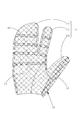
- FIG. 1 is a view of the glove-type power assist device of the present invention in a state in which the closing means 12 is closed as seen from the back side.
- FIG. 2 is a view of the glove-type power assist device of the present invention with the closing means 12 open as seen from the back side.
- FIG. 3 is a view of the glove-type power assist device of the present invention as seen from the palm side.
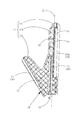
- FIG. 4 is a view of the glove-type power assist device of the present invention in a state where the index finger insertion portion 11b is extended as viewed from the thumb side.
- FIG. 5 is a view of the glove-type power assist device of the present invention in a state in which the index finger insertion portion 11b is bent as viewed from the thumb side.
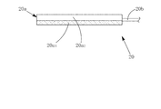
- FIG. 6 is a side view of the telescopic tube 20 in a contracted state (non-curved state).
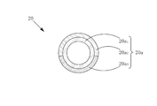
- FIG. 7 is a view showing a cross section of the expandable tube 20 in a contracted state (non-curved state) cut along a plane perpendicular to the central axis.
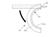
- FIG. 8 is a side view of the telescopic tube 20 in the extended state (curved state).
- FIG. 9 is a view showing a cross section of the expandable tube 20 in an expanded state (curved state) cut along a plane perpendicular to the central axis.
- the glove-type power assist device includes a glove 10, a telescopic tube 20, and a fluid supply unit (not shown).
- the glove 10 includes a finger insertion unit 11 for inserting a finger.
- the telescopic tube 20 is fixed along the back side (back side) of the finger insertion portion 11 in the glove 10.
- the telescopic tube 20 changes from a straight state as shown in FIG. 6 to a curved state as shown in FIG. It is going to change.
- the glove-type power assist device of the present embodiment uses this operation characteristic of the telescopic tube 20 to support the bending operation of the finger inserted into the finger insertion portion 11 as shown in FIGS. 4 and 5. It has become.
- the specific structure of the telescopic tube 20 will be described later.
- the telescopic tube 20 has a tube main body 20a that is intended to expand when a fluid is supplied to the inside and the internal pressure increases, and the tube main body 20a has a fluid. It is comprised with the fluid introduction pipe
- the tube main body 20 a includes an inner tube 20 a 1 and outer tubes 20 a 2 and 20 a 3 that cover the outer side of the inner tube 20 a 1 .
- the inner tube 20a 1 is formed of a stretchable material such as rubber.
- Non-contracted parts 20a 3 is provided along the side of the side to be fixed to the finger inserting portion 11 of the glove 10 in the tube body 20a. For this reason, the expansion
- Glove type power assist device of this embodiment I'm providing the non-contracted parts 20a 3 above, it performs the following bending operation. That is, as shown in FIG. 6, when fluid is supplied to the expansion tube 20 that is not curved and straight (contraction state), as shown in FIG.
- the back side (side on which the expansion / contraction part 20a 2 is provided) extends more than the side on which 20a 3 is provided, and the expansion / contraction tube 20 begins to curve to the ventral side.
- the glove-type power assist device of this embodiment As shown in FIGS. 7 and 9, there is a gap between the inner peripheral surface of the outer tubes 20a 2 and 20a 3 and the outer peripheral surface of the inner tube 20a 1. Not provided, the inner peripheral surface of the outer tubes 20a 2 and 20a 3 and the outer peripheral surface of the inner tube 20a 1 are always in close contact with each other. Thereby, it is possible to increase the responsiveness of the glove-type power assist device by causing the expansion tube 20 to start a bending operation immediately after the fluid starts to be supplied to the expansion tube 20.
- the diameter of the telescopic tube 20 increases as it changes from the contracted state (non-curved state) to the extended state (curved state). That is, when the fluid is not supplied to the telescopic tube 20, the size of the telescopic tube 20 can be reduced. Therefore, it is possible to save space when the glove-type power assist device is stored or carried.
- the diameter of the telescopic tube 20 is about 5 mm in the contracted state (non-curved state) and about 10 mm in the extended state (curved state).
- the fluid supply means supplies a fluid to the telescopic tube 20.
- the fluid supply means may use a compressor, a motor, or the like, but in the glove-type power assist device of this embodiment, the fluid supply means includes a cylinder filled with a fluid to be supplied to the telescopic tube 20, An open / close valve for opening and closing the cylinder, a valve control means for controlling the opening / closing of the open / close valve, and a morphological power source (battery, battery, etc.) for supplying power to the open / close valve and the valve control means. ing.
- the fluid supply means can be reduced in size and made suitable for carrying.
- the fluid supply means can be reduced in vibration and noise.
- the power consumption of the fluid supply means can be suppressed.
- the fluid filled in the cylinder constituting the fluid supply means may be either gas or liquid, but is preferably filled with liquefied carbon dioxide gas. This makes it possible to supply a large amount of carbon dioxide gas to the telescopic tube 20 while downsizing the cylinder. In addition, liquefied carbon dioxide is easy to handle, highly safe, and easily available.
- the cylinder has a capacity of 95 ml. With the cylinder of this capacity, it is possible to cause the glove-type power assist device to perform a gripping operation about 200 times. Even a person who frequently uses the glove-type power assist device has a sufficient capacity considering that the gripping operation is performed only about 100 times a day.
- the glove 10 has a finger insertion portion 11 for inserting a thumb insertion portion 11 a for inserting the wearer's thumb and a wearer's index finger.
- the glove-type power assist device has both operability and wearability.
- the structure of the glove-type power assist device can be simplified to reduce the cost. For example, when the five finger insertion portions 11 are provided independently, the above-described five expansion tubes 20 are also required. Three can also be used.
- one thumb support telescopic tube 21 is inserted into the thumb insertion portion 11a, and one index finger support telescopic tube 22 is inserted into the index finger insertion portion 11b in common with three fingers.
- the part 11c is provided with two three-finger support telescopic tubes 23a and 23b, and the total number of the telescopic tubes 20 is four.
- a cut is provided from the portion of the glove 10 covering the thumb side of the base of the index finger insertion portion 11 a to the attachment opening of the glove 10. .
- the break is provided with closing means 12 for closing the break.
- a wire fastener is employed as the closing means 12.
- substantially the entire glove 10 is formed of a stretchable base material 13 having stretchability. 1 to 5, the portion formed of the stretchable base material 13 is indicated by hatching with small meshes.
- the stretchable base material 13 is preferably a stretchable fabric used for sports inners. Thereby, a glove type power assist device can be worn more comfortably.
- an anti-slip portion covered with the anti-slip sheet 14 is provided on the palm side of the glove 10 with respect to the side line L 1 (FIG. 4).
- the anti-slip sheet 14 is preferably a rubber sheet. 1 to 5, the portion provided with the anti-slip sheet 14 is indicated by hatching with large eyes.
- the non-slip sheet 14 is covered only with the non-bent portion that does not overlap the finger joint in the palm including the finger insertion portion 11 as shown in FIG. ing.
- a ventral side of the side line L 1 the bent portion that overlaps the joints of finger in the finger insertion section 11 has a blank portion 16 which is not covered with the slip sheet 14.
- the stretchable base material 13 is viewed from the blank portion 16.
- the non-extensible portion is located at a location along the side line L 1 that is a boundary between the back side and the ventral side of the finger insertion portion 11 of the glove 10.
- the wire 15 is fixed.
- points along the side line L 1 in the finger insertion unit 11 is elongated in the longitudinal direction of the finger insertion portion 11 has a structure having inextensible constrained. 1 to 5, the non-extensible wire 15 is indicated by a thick line.
- the non-extensible wire 15 should just be provided along the one side surface in any finger insertion part 11.
- FIG. In the glove-type power assist device of this embodiment, as shown in FIG. 1, non-extensible at locations along the left and right side surfaces of the index finger insertion portion 11 b and locations along the left and right side surfaces of the three-finger common insertion portion 11 c.
- the wire 15 is fixed.
- the fixing method of the non-extensible wire 15 is not particularly limited.
- the non-extensible wire 15 is attached to the finger insertion portion 11 by sewing the thread-like non-extensible wire 15 along the boundary between the stretchable base material 13 and the anti-slip sheet 14. Is fixed.
- a yarn made of synthetic fiber is used as the non-extensible wire 15.
- the use of the glove type power assist device of the present invention is not particularly limited. In addition to supporting grip strength during various activities in daily life, such as holding a spoon, holding a cup, holding a pencil, etc., rehabilitation for people with disabilities, training to make the hands learn movements, and prevention of contracture Can also be used for stretching. It can also be used as a glove-type load applying device used for strength training. Furthermore, it can also be used as a glove-type sensation device used to embody virtual reality.
- the glove-type power assist device according to the present invention can smoothly support the operation of the wearer's finger without imposing an excessive load on the joint of the wearer's finger, and can be easily downsized and carried easily. Since it is suitable, it can be used for a wide range of applications as described above.
- the glove-type power assist device of the present invention can also be used when supporting the extending operation of the finger.
- the extendable tube can be extended from the bent state, thereby supporting the extension operation of the finger.
- a large support force operation force
- two types of telescopic tubes are fixed along the back side of the common finger insertion portion, and the first telescopic tube is fixed to the finger insertion portion.
- the extension along the longitudinal direction on the side is restricted (having the same structure as the expansion tube 20 in FIG. 1), while the second expansion tube is fixed to the finger insertion portion. It is assumed that the extension along the longitudinal direction on the side opposite to the applied side (back side) is restricted (with a structure that curves to the side opposite to the telescopic tube 20 in FIG. 1), and is executed by the glove-type power assist device. It is preferable to switch the expansion / contraction tube that supplies the fluid from the cylinder (fluid supply means) between the first expansion tube and the second expansion tube according to the operation.
- the fluid when the bending operation is performed, the fluid is supplied from the cylinder (fluid supply means) to the first expansion tube while discharging the fluid from the second expansion tube, and when the expansion operation is performed, The fluid may be supplied from the cylinder (fluid supply means) to the second extension tube while discharging the fluid from the first extension tube. Accordingly, it is possible to obtain a large operating force not only when supporting the bending operation of the finger but also when supporting the extending operation of the finger. This configuration can be suitably employed for any of the above-described applications.
Landscapes
- Health & Medical Sciences (AREA)
- Orthopedic Medicine & Surgery (AREA)
- General Health & Medical Sciences (AREA)
- Life Sciences & Earth Sciences (AREA)
- Physical Education & Sports Medicine (AREA)
- Engineering & Computer Science (AREA)
- Biophysics (AREA)
- Animal Behavior & Ethology (AREA)
- Veterinary Medicine (AREA)
- Public Health (AREA)
- Nursing (AREA)
- General Engineering & Computer Science (AREA)
- Heart & Thoracic Surgery (AREA)
- Biomedical Technology (AREA)
- Vascular Medicine (AREA)
- Theoretical Computer Science (AREA)
- Epidemiology (AREA)
- Rehabilitation Therapy (AREA)
- Human Computer Interaction (AREA)
- Physics & Mathematics (AREA)
- General Physics & Mathematics (AREA)
- Pain & Pain Management (AREA)
- Manipulator (AREA)
- Prostheses (AREA)
Abstract
使用時の違和感がなく、装着も容易で、日常生活において使用しやすい手袋型パワーアシスト装置を提供する。 手袋型パワーアシスト装置を、指挿入部11を備えた手袋10と、指挿入部11の背側に沿って固定されてその固定された側における長手方向に沿った伸長が制限された伸縮チューブ20と、伸縮チューブ20に流体を供給するための流体供給手段とを備え、伸縮チューブ20に流体を供給して伸縮チューブ20の腹側よりも背側を伸長させることで、伸縮チューブ20を腹側に湾曲させて手指の屈曲動作を支援するものとして、手袋10の実質的に全体を、伸縮性を有する伸縮性基材13で形成する一方、その指挿入部11の背側と腹側の境界となる脇線L1を、指挿入部11の長手方向への伸長が拘束された非伸長性を有する構造とすることにより、着用者の手指の関節の屈曲点を中心として伸縮チューブ20を湾曲させることができるようにした。
Description
本発明は、手に装着することにより、着用者の手指の動作を支援する手袋型パワーアシスト装置に関する。
少子高齢化の進行に伴い、介護者の不足がより一層深刻な問題となってきており、高齢者が高齢者を介護するいわゆる老々介護も多く見受けられるようになってきている。このため、介護者の肉体的負担を軽減したり、被介護者の自立を支援することを目的としたパワーアシスト装置に対する需要が高まってきている。パワーアシスト装置は、支援対象となる部位に応じて様々な形態のものが提案されており、手指の屈曲動作を支援することを目的とした手袋型パワーアシスト装置も既に公知となっている。
例えば、特許文献1には、流体が供給されて内部圧力が増加すると湾曲するチューブ状のアクチュエータと、アクチュエータを手指関節に沿わせて装着するための装着部(手袋)とを備えたパワーアシストグローブ(手袋型パワーアシスト装置)が記載されている。
特許文献1には、前記アクチュエータの流体受容部をアクチュエータの長手方向に沿って延在させ、アクチュエータ内部の一側面の長手方向に沿った伸長を拘束する拘束手段を設けることについても記載されている。
特許文献1には、前記アクチュエータの流体受容部をアクチュエータの長手方向に沿って延在させ、アクチュエータ内部の一側面の長手方向に沿った伸長を拘束する拘束手段を設けることについても記載されている。
特許文献1の手袋型パワーアシスト装置は、関節を急角度に折り曲げるといった類の変位の大きな動作を支援するのに適しているだけでなく、アクチュエータの屈曲中心を手指の関節の屈曲中心と一致させることで着用者が感じる拘束感を軽減することも可能なものとなっている。しかし、特許文献1の手袋型パワーアシスト装置では、アクチュエータの屈曲中心が手指の関節の屈曲中心と一致するものではあるが、それはアクチュエータが変形する際にアクチュエータの屈曲中心が関節の屈曲中心に徐々に近づいていくという過程をたどるため、その際に着用者が手指の関節付近に感ずる違和感までを完全に取り除くことができるものとはなっていなかった。また、特許文献1の手袋型パワーアシスト装置は、必ずしも、小型化が容易で携帯しやすいものとはなっていなかった。
本発明は、使用時の違和感がなく、装着も容易で、日常生活において使用しやすい手袋型パワーアシスト装置を提供するものである。具体的には、特許文献1の手袋型パワーアシスト装置のように、アクチュエータが変形するに従ってアクチュエータの屈曲中心が手指の関節の屈曲中心に徐々に近づいていくという過程をたどるのではなく、アクチュエータが変形し始めた当初から、アクチュエータの屈曲中心が手指の関節の屈曲中心に一致し、着用者の手指の関節に無理な負荷を掛けることなく、着用者の手指の動作をスムーズに支援することができ、着用者が手指の関節付近に感ずる違和感を完全に取り除くことができるパワーアシスト装置を提供するものである。また、小型化が容易で携帯しやすい手袋型パワーアシスト装置を提供することも本発明の目的である。
上記課題は、手指を挿入するための指挿入部を備えた手袋と、手袋における指挿入部の背側に沿って固定されて指挿入部に対して固定された側における長手方向に沿った伸長が制限された伸縮チューブと、伸縮チューブに流体を供給するための流体供給手段とを備え、伸縮チューブに流体を供給して伸縮チューブの腹側よりも背側を伸長させることで、伸縮チューブを腹側に湾曲させ、指挿入部に挿入された手指の屈曲動作を支援する手袋型パワーアシスト装置であって、手袋の実質的に全体を、伸縮性を有する伸縮性基材で形成する一方、その指挿入部の背側と腹側の境界となる脇線(指挿入部の側面を甲側と掌側とに二分する側面の中心に沿った仮想線)を、指挿入部の長手方向への伸長が拘束された非伸長性を有する構造(全く伸長できない構造だけでなく、僅かに伸長できる構造も含む。)とすることにより、着用者の手指の関節の屈曲点を中心として伸縮チューブを湾曲させることができるようにしたことを特徴とする手袋型パワーアシスト装置を提供することによって解決される。
これにより、手指の関節の屈曲点を中心として伸縮チューブをスムーズに湾曲させることが可能になる。したがって、手袋型パワーアシスト装置の着用者の手指の関節に無理な負荷を掛けることなく、着用者の手指の動作を支援することが可能になる。ここで、「支援(アシスト)」とは、支援対象部(手指)の動作に対して順方向に力を加えて該支援対象部の動作を文字通り支援する場合だけでなく、支援対象部の動作に対して逆方向に力を加えて該支援対象部の動作を逆方向に支援する場合をも含む概念である。後者の場合を「支援(アシスト)」に含むとしたのは、リハビリや筋力トレーニングに用いられる手袋型の負荷付与装置や、バーチャルリアリティの体現に用いられる手袋型の体感装置等が、本発明の手袋型パワーアシスト装置の技術的範囲に含まれることを明確にするためである。
本発明の手袋型パワーアシスト装置において、指挿入部の脇線は、上述したように、指挿入部の背側と腹側の境界となる箇所に設ければよいが、より厳密には、指挿入部を側方から見た際に着用者の手指の関節の屈曲点を結ぶ線に重なる位置に設けると好ましい。これにより、伸縮チューブの屈曲中心を着用者の手指の関節の屈曲中心により正確に一致させることが可能になる。指挿入部の脇線を重ねる手指の関節の具体的な名称としては、人差指、中指、薬指又は小指においては、DIP関節(遠位指節間関節)やPIP関節(近位指節間関節)やMP関節(中手指節間関節)が挙げられ、親指においては、IP関節(指節間関節)やMP関節(中手指節間関節)が挙げられる。
また、本発明の手袋型パワーアシスト装置において、指挿入部の脇線を非伸長性を有する構造とするための具体的な方法は、特に限定されない。例えば、非伸長性線材(全く伸長できないものだけでなく、僅かに伸長できるものも含む。)を指挿入部の脇線に沿って固定することにより、指挿入部の脇線を非伸長性を有する構造とする方法などが挙げられる。非伸長性線材(非伸長線材)としては、ポリエステル糸などの合成繊維や、あるいは綿糸などの天然繊維が例示される。非伸長性線材は、金属製であってもよい。また、非伸長性線材は、糸状のものだけでなく、帯状のものも含まれる。指挿入部に対する非伸長性線材の固定方法としては、接着や縫着が例示される。非伸長性線材として糸状のものを使用する場合には、その糸自体を指挿入部へ縫い付けるとよい。
さらに、本発明の手袋型パワーアシスト装置においては、指挿入部における手指の関節に重ならない非屈曲部であって前記脇線よりも腹側の部分を滑り止めシートで覆われた滑り止め部とする一方、指挿入部における手指の関節に重なる屈曲部であって前記脇線よりも腹側の部分を滑り止めシートで覆われずに前記伸縮性基材が覗いた空白部とすることも好ましい。これにより、手袋型パワーアシスト装置の操作性を犠牲にすることなく、それを着用した状態で物をしっかりと掴むことが可能になる。前記空白部は、指挿入部を側方から見た際に三角形状(指挿入部の腹側が底辺となり、脇線周辺が頂点となる三角形状)となるように設けると好適である。前記空白部の個数は、各指の関節の数に一致させる。すなわち、親指を挿入する指挿入部(後述する親指挿入部)には、前記空白部を2箇所(IP関節(第一関節)用とMP関節(第二関節)用)に設け、その他の指を挿入する指挿入部(後述する人差指挿入部や三指共通挿入部)には、前記空白部を3箇所(DIP関節(第一関節)用とPIP関節(第二関節)用とMP関節(第三関節)用)に設けるとよい。
さらにまた、本発明の手袋型パワーアシスト装置においては、手袋における人差指の付根の親指側を覆う部分から手袋の装着口にかけて切れ目を設け、該切れ目を閉塞するための閉塞手段を設けることも好ましい。これにより、手袋型パワーアシスト装置を装着しやすくすることが可能になる。特に、手先の不自由な人でも簡単に手袋型パワーアシスト装置を着用することができるようになる。加えて、手袋型パワーアシスト装置の製造(縫製など)やメンテナンス(伸縮チューブの交換など)を容易に行うことも可能になる。前記切れ目の閉塞手段としては、線ファスナーや、面ファスナーや、点ファスナーなどの各種ファスナーが例示される。なかでも、線ファスナーは、前記切れ目を連続的に閉塞できることに加えて、意図的に操作しない限りは開かないために、前記切れ目の閉塞手段として好適に使用することができる。
そして、本発明の手袋型パワーアシスト装置において、手袋の形態(指挿入部の別れ方)は、特に限定されない。手袋の指挿入部は、着用者の親指を挿入するための親指挿入部と、人差指を挿入するための人差指挿入部と、中指を挿入するための中指挿入部と、薬指を挿入するための薬指挿入部と、小指を挿入するための小指挿入部とで構成されていてもよいが、中指挿入部と薬指挿入部と小指挿入部とを1つの指挿入部(三指共通挿入部)にまとめると好ましい。このように、手袋の指挿入部を、親指挿入部と、人差指挿入部と、三指共通挿入部とで構成することで、手袋型パワーアシスト装置の操作性と、装着のしやすさをさらに向上させることが可能になる。加えて、三指共通挿入部に固定する伸縮チューブの本数を削減することができるので、手袋型パワーアシスト装置のコストを抑えることも可能になる。これに対し、人差指挿入部と中指挿入部と薬指挿入部と小指挿入部とを1つの指挿入部(四指共通挿入部)にまとめて、手袋の指挿入部を、親指挿入部と四指共通挿入部とで構成すると、手袋型パアーアシスト装置の装着のしやすさやコスト的にはさらに有利になるものの、手袋型パワーアシスト装置の操作性が低下するという欠点がある。
そしてまた、本発明の手袋型パワーアシスト装置において、流体供給手段の種類は特に限定されないが、容量が500ml以下とされてその内部に液化炭酸ガスが充填されたボンベと、該ボンベの開閉を行う開閉弁と、該開閉弁の開閉を制御するための弁制御手段とで構成されたものであると好ましい。これにより、流体供給手段を小型化して携帯しやすいものとすることができる。したがって、手袋型パワーアシスト装置も小型化して携帯しやすいものとすることが可能になる。前記ボンベの容量は、300ml以下であると好ましく、200ml以下であるとより好ましい。一方、前記ボンベの容量が小さすぎると、前記ボンベに充填された液化炭酸ガスが短時間でなくなり、液化炭酸ガスの充填や前記ボンベの交換が頻繁になってしまう。このため、前記ボンベの容量は、通常、10ml以上とされる。前記ボンベの容量は、30ml以上であると好ましく、50ml以上であるとより好ましい。
以上のように、本発明によって、使用時の違和感がなく、装着も容易で、日常生活において使用しやすい手袋型パワーアシスト装置を提供することが可能になる。具体的には、特許文献1の手袋型パワーアシスト装置のように、アクチュエータが変形するに従ってアクチュエータの屈曲中心が手指の関節の屈曲中心に徐々に近づいていくという過程をたどるのではなく、アクチュエータが変形し始めた当初から、アクチュエータの屈曲中心が手指の関節の屈曲中心に一致し、着用者の手指の関節に無理な負荷を掛けることなく、着用者の手指の動作をスムーズに支援することができ、着用者が手指の関節付近に感ずる違和感を完全に取り除くことができるパワーアシスト装置を提供することが可能になる。また、小型化が容易で携帯しやすい手袋型パワーアシスト装置を提供することも可能になる。
本発明の手袋型パワーアシスト装置の好適な実施態様について、図面を用いてより具体的に説明する。図1は、閉塞手段12を閉じた状態の本発明の手袋型パワーアシスト装置を甲側から見た図である。図2は、閉塞手段12を開いた状態の本発明の手袋型パワーアシスト装置を甲側から見た図である。図3は、本発明の手袋型パワーアシスト装置を掌側から見た図である。図4は、人差指挿入部11bを伸ばした状態の本発明の手袋型パワーアシスト装置を親指側から見た図である。図5は、人差指挿入部11bを曲げた状態の本発明の手袋型パワーアシスト装置を親指側から見た図である。図6は、収縮状態(非湾曲状態)の伸縮チューブ20を側方から見た図である。図7は、収縮状態(非湾曲状態)の伸縮チューブ20を中心軸に垂直な平面で切断した断面を示した図である。図8は、伸長状態(湾曲状態)の伸縮チューブ20を側方から見た図である。図9は、伸長状態(湾曲状態)の伸縮チューブ20を中心軸に垂直な平面で切断した断面を示した図である。
[概要]
本実施態様の手袋型パワーアシスト装置は、図1に示すように、手袋10と、伸縮チューブ20と、流体供給手段(図示省略)とを備えている。手袋10は、手指を挿入するための指挿入部11を備えている。伸縮チューブ20は、図4に示すように、手袋10における指挿入部11の背側(甲側)に沿って固定されている。流体供給手段から伸縮チューブ20へ流体が供給されて、伸縮チューブ20の内部圧力が高まると、伸縮チューブ20は、図6に示すように真っ直ぐな状態から図8に示すように湾曲した状態へと変化するようになっている。本実施態様の手袋型パワーアシスト装置は、伸縮チューブ20のこの動作特性を利用して、図4と図5に示すように、指挿入部11に挿入された手指の屈曲動作を支援するものとなっている。伸縮チューブ20の具体的な構造については後述する。
本実施態様の手袋型パワーアシスト装置は、図1に示すように、手袋10と、伸縮チューブ20と、流体供給手段(図示省略)とを備えている。手袋10は、手指を挿入するための指挿入部11を備えている。伸縮チューブ20は、図4に示すように、手袋10における指挿入部11の背側(甲側)に沿って固定されている。流体供給手段から伸縮チューブ20へ流体が供給されて、伸縮チューブ20の内部圧力が高まると、伸縮チューブ20は、図6に示すように真っ直ぐな状態から図8に示すように湾曲した状態へと変化するようになっている。本実施態様の手袋型パワーアシスト装置は、伸縮チューブ20のこの動作特性を利用して、図4と図5に示すように、指挿入部11に挿入された手指の屈曲動作を支援するものとなっている。伸縮チューブ20の具体的な構造については後述する。
[伸縮チューブ]
本実施他用の手袋型パワーアシスト装置において、伸縮チューブ20は、図6に示すように、内部に流体が供給されて内部圧力が高まると膨張しようとするチューブ本体20aと、チューブ本体20aに流体を導入するための流体導入管20bとで構成されている。チューブ本体20aは、図7に示すように、内側チューブ20a1と、内側チューブ20a1の外側を被覆する外側チューブ20a2,20a3とで構成されている。
本実施他用の手袋型パワーアシスト装置において、伸縮チューブ20は、図6に示すように、内部に流体が供給されて内部圧力が高まると膨張しようとするチューブ本体20aと、チューブ本体20aに流体を導入するための流体導入管20bとで構成されている。チューブ本体20aは、図7に示すように、内側チューブ20a1と、内側チューブ20a1の外側を被覆する外側チューブ20a2,20a3とで構成されている。
内側チューブ20a1と外側チューブ20a2,20a3のうち、内側チューブ20a1は、ゴムなどの伸縮可能な素材で形成される。これに対し、外側チューブ20a2,20a3は、ゴムなどの伸縮素材で形成された伸縮部20a2と、布などの非伸縮素材で形成された非伸縮部20a3とで構成される。非伸縮部20a3は、チューブ本体20aにおける手袋10の手指挿入部11に固定される側の側面に沿って設けられている。このため、伸縮チューブ20の腹側(伸縮チューブ20における指挿入部11に対して固定される側)の長手方向に沿った伸長は、制限された状態となっている。
本実施態様の手袋型パワーアシスト装置は、上記の非伸縮部20a3を設けたことよって、次のような湾曲動作を行う。すなわち、図6に示すように、湾曲しておらず真っ直ぐな状態(収縮状態)の伸縮チューブ20に流体が供給されると、図8に示すように、伸縮チューブ20の腹側(非伸縮部20a3が設けられた側)よりも背側(伸縮部20a2が設けられた側)が伸長し、伸縮チューブ20が腹側に湾曲し始める。この湾曲動作により、図4と図5に示すように、手袋型パワーアシスト装置の着用者の手指の屈曲動作が支援される。
ところで、本実施態様の手袋型パワーアシスト装置では、図7と図9に示すように、外側チューブ20a2,20a3の内周面と、内側チューブ20a1の外周面との間には隙間を設けておらず、外側チューブ20a2,20a3の内周面と内側チューブ20a1の外周面とが常に密着するようにしている。これにより、伸縮チューブ20に流体を供給し始めた直後から伸縮チューブ20に湾曲動作を開始させ、手袋型パワーアシスト装置の応答性を高めることが可能になっている。
また、伸縮チューブ20は、収縮状態(非湾曲状態)から伸長状態(湾曲状態)へ推移するに連れて、径が大きくなるようになっている。すなわち、伸縮チューブ20に流体を供給していない状態にあっては、伸縮チューブ20の寸法を小さくすることができる。したがって、手袋型パワーアシスト装置を収納したり持ち運びしたりする際の省スペース化を図ることができるようになっている。本実施態様の手袋型パワーアシスト装置において、伸縮チューブ20の径は、収縮状態(非湾曲状態)において約5mm、伸長状態(湾曲状態)において約10mmとなっている。
[流体供給手段]
流体供給手段は、伸縮チューブ20に流体を供給する。流体供給手段は、コンプレッサーやモーターなどを使用するものであってもよいが、本実施態様の手袋型パワーアシスト装置において、流体供給手段は、伸縮チューブ20に供給する流体を充填したボンベと、該ボンベの開閉を行う開閉弁と、該開閉弁の開閉を制御するための弁制御手段と、開閉弁及び弁制御手段に電力を供給するための形態型電源(バッテリーや電池など)とで構成している。これにより、流体供給手段を小型化して携帯に適したものとすることができる。また、流体供給手段を振動や騒音の少ないものとすることが可能になる。さらに、流体供給手段の消費電力を抑えることもできる。
流体供給手段は、伸縮チューブ20に流体を供給する。流体供給手段は、コンプレッサーやモーターなどを使用するものであってもよいが、本実施態様の手袋型パワーアシスト装置において、流体供給手段は、伸縮チューブ20に供給する流体を充填したボンベと、該ボンベの開閉を行う開閉弁と、該開閉弁の開閉を制御するための弁制御手段と、開閉弁及び弁制御手段に電力を供給するための形態型電源(バッテリーや電池など)とで構成している。これにより、流体供給手段を小型化して携帯に適したものとすることができる。また、流体供給手段を振動や騒音の少ないものとすることが可能になる。さらに、流体供給手段の消費電力を抑えることもできる。
流体供給手段を構成するボンベに充填する流体は、気体又は液体のいずれであってもよいが、液化炭酸ガスを充填すると好ましい。これにより、前記ボンベを小型化しながらも、伸縮チューブ20に大量の炭酸ガスを供給することが可能になる。また、液化炭酸ガスは、取り扱いも容易で安全性も高く、入手も容易である。本実施態様の手袋型パワーアシスト装置において、前記ボンベの容量は95mlとなっている。この容量のボンベで、手袋型パワーアシスト装置に約200回の把持動作を行わせることが可能である。手袋型パワーアシスト装置を頻繁に使用する人でも、1日で約100回程度しか把持動作を行わないことを考慮すると十分な容量である。
[手袋]
本実施態様の手袋型パワーアシスト装置において、手袋10は、図1に示すように、その指挿入部11が、着用者の親指を挿入するための親指挿入部11aと、着用者の人差指を挿入するための人差指挿入部11bと、着用者の中指、薬指及び小指を共に挿入するための三指共通挿入部11cとで構成されている。このため、手袋型パワーアシスト装置は、操作性と装着性を兼ね備えたものとなっている。また、手袋型パワーアシスト装置の構造を簡素化してコストを削減することも可能となっている。例えば、5本の指挿入部11を独立して設けると、上記の伸縮チューブ20も5本必要となるところ、上述したような三指共通挿入部11cを設けると、上記の伸縮チューブ20は最低3本とすることもできる。本実施態様の手袋型パワーアシスト装置においては、親指挿入部11aには1本の親指支援用伸縮チューブ21を、人差指挿入部11bには1本の人差指支援用伸縮チューブ22を、三指共通挿入部11cには2本の三指支援用伸縮チューブ23a,23bをそれぞれ設けており、伸縮チューブ20の本数は合計4本となっている。
本実施態様の手袋型パワーアシスト装置において、手袋10は、図1に示すように、その指挿入部11が、着用者の親指を挿入するための親指挿入部11aと、着用者の人差指を挿入するための人差指挿入部11bと、着用者の中指、薬指及び小指を共に挿入するための三指共通挿入部11cとで構成されている。このため、手袋型パワーアシスト装置は、操作性と装着性を兼ね備えたものとなっている。また、手袋型パワーアシスト装置の構造を簡素化してコストを削減することも可能となっている。例えば、5本の指挿入部11を独立して設けると、上記の伸縮チューブ20も5本必要となるところ、上述したような三指共通挿入部11cを設けると、上記の伸縮チューブ20は最低3本とすることもできる。本実施態様の手袋型パワーアシスト装置においては、親指挿入部11aには1本の親指支援用伸縮チューブ21を、人差指挿入部11bには1本の人差指支援用伸縮チューブ22を、三指共通挿入部11cには2本の三指支援用伸縮チューブ23a,23bをそれぞれ設けており、伸縮チューブ20の本数は合計4本となっている。
また、本実施態様の手袋型パワーアシスト装置においては、図2に示すように、手袋10における人差指挿入部11aの付根の親指側を覆う部分から手袋10の装着口にかけては、切れ目を設けている。この切れ目には、該切れ目を閉塞するための閉塞手段12を設けている。このため、手先の不自由な人でも簡単に手袋型パワーアシスト装置を着用することができるようになっている。特に、最も挿入しにくい親指挿入部11aへ親指を容易に挿入できるようになっている。本実施態様の手袋型パワーアシスト装置においては、閉塞手段12として線ファスナーを採用している。
手袋10の実質的に全体は、図1に示すように、伸縮性を有する伸縮性基材13で形成されている。図1~5において、伸縮性基材13で形成された部分は、目の小さい網掛けハッチングで示してある。伸縮性基材13は、スポーツ用インナーなどに使用される伸縮性生地を使用すると好ましい。これにより、手袋型パワーアシスト装置をより違和感なく着用できるものとすることができる。また、手袋10における脇線L1(図4)よりも掌側には、図3に示すように、滑り止めシート14で覆われた滑り止め部が設けられている。滑り止めシート14は、ラバーシートを使用すると好ましい。図1~5において、滑り止めシート14が設けられた部分は、目の大きい網掛けハッチングで示してある。
本実施態様の手袋型パワーアシスト装置において、滑り止めシート14で覆われているのは、図3に示すように、指挿入部11を含む掌における手指の関節に重ならない非屈曲部のみとなっている。換言すると、脇線L1よりも腹側であって、指挿入部11における手指の関節に重なる屈曲部は、滑り止めシート14で覆われていない空白部16となっている。空白部16からは伸縮性基材13が覗いた状態となっている。これにより、指挿入部11を屈曲しやすくして、手袋型パワーアシスト装置の操作性や着用感を向上することができる。
また、本実施態様の手袋型パワーアシスト装置において、手袋10の指挿入部11の背側と腹側の境界となる脇線L1に沿った箇所には、図4に示すように、非伸長性線材15が固定されている。このため、指挿入部11における脇線L1に沿った箇所は、指挿入部11の長手方向への伸長が拘束された非伸長性を有する構造となっている。図1~5において、非伸長性線材15は、太線で示してある。非伸長性線材15は、いずれかの指挿入部11における片方の側面に沿って設けられていればよい。本実施態様の手袋型パワーアシスト装置では、図1に示すように、人差指挿入部11bの左右の側面に沿った箇所と、三指共通挿入部11cの左右の側面に沿った箇所に非伸長性線材15を固定している。
非伸長性線材15の固定方法は、特に限定されない。本実施態様の手袋型パワーアシスト装置では、伸縮性基材13と滑り止めシート14との境界に沿って糸状の非伸長性線材15を縫い付けることにより、指挿入部11に非伸長性線材15を固定している。非伸長性線材15としては、合成繊維からなる糸を用いている。このようにすることで、伸縮チューブ20が湾曲した際に、指挿入部11の屈曲中心が、着用者の手指関節の屈曲中心により速やかにかつより確実に一致させることが可能になる。したがって、着用者の感じる違和感をさらに軽減することができる。
[用途]
本発明の手袋型パワーアシスト装置の用途は、特に限定されない。スプーンを持つ、コップを持つ、鉛筆を持つなど、日常生活における各種動作の際の握力支援のほか、手先の不自由な人のリハビリテーションや、手先に動きを覚えさせるためのトレーニングや、拘縮予防のストレッチなどにも使用することができる。また、筋力トレーニングに用いられる手袋型の負荷付与装置としても用いることができる。さらに、バーチャルリアリティの体現に用いられる手袋型の体感装置などとしても用いることができる。本発明の手袋型パワーアシスト装置は、着用者の手指の関節に無理な負荷を掛けることなく、着用者の手指の動作をスムーズに支援することができることに加え、小型化も容易で携帯にも適しているため、上記のような幅広い用途に用いることができる。
本発明の手袋型パワーアシスト装置の用途は、特に限定されない。スプーンを持つ、コップを持つ、鉛筆を持つなど、日常生活における各種動作の際の握力支援のほか、手先の不自由な人のリハビリテーションや、手先に動きを覚えさせるためのトレーニングや、拘縮予防のストレッチなどにも使用することができる。また、筋力トレーニングに用いられる手袋型の負荷付与装置としても用いることができる。さらに、バーチャルリアリティの体現に用いられる手袋型の体感装置などとしても用いることができる。本発明の手袋型パワーアシスト装置は、着用者の手指の関節に無理な負荷を掛けることなく、着用者の手指の動作をスムーズに支援することができることに加え、小型化も容易で携帯にも適しているため、上記のような幅広い用途に用いることができる。
ところで、ここまでは、主に手指の屈曲動作を支援する場合を例に挙げて説明したが、本発明の手袋型パワーアシスト装置は、手指の伸長動作を支援する場合にも使用することができる。すなわち、流体が供給されて湾曲状態にある伸縮チューブから流体を排出させれば、伸縮チューブを湾曲状態から伸長させ、手指の伸長動作を支援することもできる。ただし、この場合には、伸長動作の際に大きな支援力(操作力)を得ることができない場合がある。このため、共通の指挿入部の背側に沿って2種類の伸縮チューブ(第一の伸縮チューブと第二の伸縮チューブ)を固定し、第一の伸縮チューブを、指挿入部に対して固定された側(腹側)における長手方向に沿った伸長が制限されたもの(図1における伸縮チューブ20と同じ構造のもの)とする一方、第二の伸縮チューブを、指挿入部に対して固定された側とは反対側(背側)における長手方向に沿った伸長が制限されたもの(図1における伸縮チューブ20と反対側に湾曲する構造のもの)とし、手袋型パワーアシスト装置に実行させる動作に応じて、ボンベ(流体供給手段)から流体を供給する伸縮チューブを第一の伸縮チューブと第二の伸縮チューブとで切り替えるようにすると好ましい。具体的には、屈曲動作をさせる場合には、第二の伸縮チューブから流体を排出しながらボンベ(流体供給手段)から第一の伸縮チューブへ流体を供給し、伸長動作をさせる場合には、第一の伸縮チューブから流体を排出しながらボンベ(流体供給手段)から第二の伸縮チューブへ流体を供給するとよい。これにより、手指の屈曲動作を支援する場合だけでなく、手指の伸長動作を支援する場合にも大きな操作力を得ることが可能になる。この構成は、上述したいずれの用途に対しても好適に採用することができる。
10 手袋
11 指挿入部
11a 親指挿入部
11b 人差指挿入部
11c 三指共通挿入部
12 閉塞手段
13 伸縮性基材
14 滑り止めシート
15 非伸長性線材
16 空白部
20 伸縮チューブ
20a チューブ本体
20a1 内側チューブ
20a2 伸縮部(外側チューブ)
20a3 非伸縮部(外側チューブ)
20b 流体導入管
21 親指支援用伸縮チューブ
22 人差指支援用伸縮チューブ
23a 三指支援用伸縮チューブ
23b 三指支援用伸縮チューブ
L1 脇線
11 指挿入部
11a 親指挿入部
11b 人差指挿入部
11c 三指共通挿入部
12 閉塞手段
13 伸縮性基材
14 滑り止めシート
15 非伸長性線材
16 空白部
20 伸縮チューブ
20a チューブ本体
20a1 内側チューブ
20a2 伸縮部(外側チューブ)
20a3 非伸縮部(外側チューブ)
20b 流体導入管
21 親指支援用伸縮チューブ
22 人差指支援用伸縮チューブ
23a 三指支援用伸縮チューブ
23b 三指支援用伸縮チューブ
L1 脇線
Claims (7)
- (a)手指を挿入するための指挿入部を備えた手袋と、
(b)手袋における指挿入部の背側に沿って固定され、指挿入部に対して固定された側における長手方向に沿った伸長が制限された伸縮チューブと、
(c)伸縮チューブに流体を供給するための流体供給手段と、
を備え、
伸縮チューブに流体を供給して伸縮チューブの腹側よりも背側を伸長させることで、伸縮チューブを腹側に湾曲させ、指挿入部に挿入された手指の屈曲動作を支援する手袋型パワーアシスト装置であって、
手袋の実質的に全体が、伸縮性を有する伸縮性基材で形成される一方、その指挿入部の背側と腹側の境界となる脇線は、指挿入部の長手方向への伸長が拘束された非伸長性を有する構造とされたことにより、着用者の手指の関節の屈曲点を中心として伸縮チューブを湾曲させることができるようにしたことを特徴とする手袋型パワーアシスト装置。 - 指挿入部の脇線が、指挿入部を側方から見た際に着用者の手指の関節の屈曲点を結ぶ線に重なる位置に設けられた請求項1記載の手袋型パワーアシスト装置。
- 非伸長性線材を指挿入部の脇線に沿って固定することにより、指挿入部の脇線が非伸長性を有する構造とされた請求項1又は2記載の手袋型パワーアシスト装置。
- 指挿入部における手指の関節に重ならない非屈曲部であって前記脇線よりも腹側の部分を滑り止めシートで覆われた滑り止め部とする一方、指挿入部における手指の関節に重なる屈曲部であって前記脇線よりも腹側の部分を滑り止めシートで覆われずに前記伸縮性基材が覗いた空白部とした請求項1~3いずれか記載の手袋型パワーアシスト装置。
- 手袋における人差指の付根の親指側を覆う部分から手袋の装着口にかけて切れ目を設け、該切れ目を閉塞するための閉塞手段を設けた請求項1~4いずれか記載の手袋型パワーアシスト装置。
- 手袋の指挿入部が、着用者の親指を挿入するための親指挿入部と、着用者の人差指を挿入するための人差指挿入部と、着用者の中指、薬指及び小指を共に挿入するための三指共通挿入部とで構成された請求項1~5いずれか記載の手袋型パワーアシスト装置。
- 流体供給手段が、容量が500ml以下とされてその内部に液化炭酸ガスが充填されたボンベと、該ボンベの開閉を行う開閉弁と、該開閉弁の開閉を制御するための弁制御手段とで構成された請求項1~6いずれか記載の手袋型パワーアシスト装置。
Priority Applications (4)
| Application Number | Priority Date | Filing Date | Title |
|---|---|---|---|
| DK12757696.5T DK2687191T3 (en) | 2011-03-16 | 2012-03-06 | Motion-assist device in the glove form |
| EP12757696.5A EP2687191B8 (en) | 2011-03-16 | 2012-03-06 | Glove-type power assist device |
| CN201280013509.9A CN103442667B (zh) | 2011-03-16 | 2012-03-06 | 手套型助力装置 |
| JP2013504671A JP5957786B2 (ja) | 2011-03-16 | 2012-03-06 | 手袋型パワーアシスト装置 |
Applications Claiming Priority (2)
| Application Number | Priority Date | Filing Date | Title |
|---|---|---|---|
| JP2011057791 | 2011-03-16 | ||
| JP2011-057791 | 2011-03-16 |
Publications (1)
| Publication Number | Publication Date |
|---|---|
| WO2012124546A1 true WO2012124546A1 (ja) | 2012-09-20 |
Family
ID=46830621
Family Applications (1)
| Application Number | Title | Priority Date | Filing Date |
|---|---|---|---|
| PCT/JP2012/055694 WO2012124546A1 (ja) | 2011-03-16 | 2012-03-06 | 手袋型パワーアシスト装置 |
Country Status (5)
| Country | Link |
|---|---|
| EP (1) | EP2687191B8 (ja) |
| JP (1) | JP5957786B2 (ja) |
| CN (1) | CN103442667B (ja) |
| DK (1) | DK2687191T3 (ja) |
| WO (1) | WO2012124546A1 (ja) |
Cited By (5)
| Publication number | Priority date | Publication date | Assignee | Title |
|---|---|---|---|---|
| WO2015066143A1 (en) * | 2013-10-29 | 2015-05-07 | President And Fellows Of Harvard College | Multi-segment reinforced actuators and applications |
| CN105212374A (zh) * | 2015-11-04 | 2016-01-06 | 杨丽珍 | 带有口袋的分体式防晒手套 |
| JP2017504489A (ja) * | 2013-10-18 | 2017-02-09 | プレジデント アンド フェローズ オブ ハーバード カレッジ | 適合スリーブを備えた機械的にプログラムされたソフトアクチュエータ |
| JP2017526543A (ja) * | 2014-08-22 | 2017-09-14 | プレジデント アンド フェローズ オブ ハーバード カレッジ | ソフトロボットおよびソフトアクチュエータのためのセンサ |
| US10792807B2 (en) | 2014-08-22 | 2020-10-06 | President And Fellows Of Harvard College | Flexible and stretchable electronic strain-limited layer for soft actuators |
Families Citing this family (9)
| Publication number | Priority date | Publication date | Assignee | Title |
|---|---|---|---|---|
| US20170119614A1 (en) * | 2014-06-12 | 2017-05-04 | National University Of Singapore | Actuator device, method and system for limb rehabilitation |
| CN105161028A (zh) * | 2015-09-25 | 2015-12-16 | 陈玉堂 | 一种便携式打车识别装置 |
| KR101814676B1 (ko) * | 2016-07-25 | 2018-01-04 | 이동찬 | 소프트 외골격 근력 보조 장치 |
| US11129766B2 (en) | 2017-04-14 | 2021-09-28 | The Chinese University Of Hong Kong | Flexibly driven robotic hands |
| WO2019203732A1 (en) * | 2018-04-20 | 2019-10-24 | Roceso Technologies Private Limited | Wearable hand assistive device and system |
| CN112040922B (zh) * | 2018-05-23 | 2022-11-08 | 香港大学 | 康复用柔软机器人手套 |
| CN109953871B (zh) * | 2019-04-11 | 2021-05-11 | 无锡市第九人民医院 | 一种利用气压分布状态进行训练的手指复健用指套 |
| CN111228748B (zh) * | 2020-01-13 | 2020-12-01 | 吉林大学 | 一种icu重症医疗用手部束缚组件 |
| CN111789745B (zh) * | 2020-08-25 | 2022-11-15 | 河南科技大学 | 一种气动康复手套 |
Citations (4)
| Publication number | Priority date | Publication date | Assignee | Title |
|---|---|---|---|---|
| US4739692A (en) * | 1984-05-29 | 1988-04-26 | Fluidic Motion Corporation | Liquid contractility actuator |
| US6168634B1 (en) * | 1999-03-25 | 2001-01-02 | Geoffrey W. Schmitz | Hydraulically energized magnetorheological replicant muscle tissue and a system and a method for using and controlling same |
| JP2001276101A (ja) * | 2000-03-29 | 2001-10-09 | Seiko Epson Corp | 身体装着型筋力補助装置 |
| JP2006000294A (ja) | 2004-06-16 | 2006-01-05 | Toshirou Noritsugi | 装着型パワーアシスト装置 |
Family Cites Families (2)
| Publication number | Priority date | Publication date | Assignee | Title |
|---|---|---|---|---|
| JP2004329490A (ja) * | 2003-05-06 | 2004-11-25 | Osaka Industrial Promotion Organization | 指運動機能回復支援具および指運動機能回復支援システム |
| JP5472680B2 (ja) * | 2009-04-09 | 2014-04-16 | 国立大学法人 筑波大学 | 装着式動作補助装置 |
-
2012
- 2012-03-06 JP JP2013504671A patent/JP5957786B2/ja not_active Expired - Fee Related
- 2012-03-06 DK DK12757696.5T patent/DK2687191T3/en active
- 2012-03-06 CN CN201280013509.9A patent/CN103442667B/zh not_active Expired - Fee Related
- 2012-03-06 EP EP12757696.5A patent/EP2687191B8/en not_active Not-in-force
- 2012-03-06 WO PCT/JP2012/055694 patent/WO2012124546A1/ja active Application Filing
Patent Citations (4)
| Publication number | Priority date | Publication date | Assignee | Title |
|---|---|---|---|---|
| US4739692A (en) * | 1984-05-29 | 1988-04-26 | Fluidic Motion Corporation | Liquid contractility actuator |
| US6168634B1 (en) * | 1999-03-25 | 2001-01-02 | Geoffrey W. Schmitz | Hydraulically energized magnetorheological replicant muscle tissue and a system and a method for using and controlling same |
| JP2001276101A (ja) * | 2000-03-29 | 2001-10-09 | Seiko Epson Corp | 身体装着型筋力補助装置 |
| JP2006000294A (ja) | 2004-06-16 | 2006-01-05 | Toshirou Noritsugi | 装着型パワーアシスト装置 |
Non-Patent Citations (1)
| Title |
|---|
| See also references of EP2687191A4 * |
Cited By (6)
| Publication number | Priority date | Publication date | Assignee | Title |
|---|---|---|---|---|
| JP2017504489A (ja) * | 2013-10-18 | 2017-02-09 | プレジデント アンド フェローズ オブ ハーバード カレッジ | 適合スリーブを備えた機械的にプログラムされたソフトアクチュエータ |
| WO2015066143A1 (en) * | 2013-10-29 | 2015-05-07 | President And Fellows Of Harvard College | Multi-segment reinforced actuators and applications |
| JP2017526543A (ja) * | 2014-08-22 | 2017-09-14 | プレジデント アンド フェローズ オブ ハーバード カレッジ | ソフトロボットおよびソフトアクチュエータのためのセンサ |
| US10576643B2 (en) | 2014-08-22 | 2020-03-03 | President And Fellows Of Harvard College | Sensors for soft robots and soft actuators |
| US10792807B2 (en) | 2014-08-22 | 2020-10-06 | President And Fellows Of Harvard College | Flexible and stretchable electronic strain-limited layer for soft actuators |
| CN105212374A (zh) * | 2015-11-04 | 2016-01-06 | 杨丽珍 | 带有口袋的分体式防晒手套 |
Also Published As
| Publication number | Publication date |
|---|---|
| CN103442667A (zh) | 2013-12-11 |
| JPWO2012124546A1 (ja) | 2014-07-24 |
| DK2687191T3 (en) | 2016-04-25 |
| EP2687191A4 (en) | 2014-10-15 |
| EP2687191A1 (en) | 2014-01-22 |
| EP2687191B8 (en) | 2016-05-11 |
| CN103442667B (zh) | 2015-08-19 |
| EP2687191B1 (en) | 2016-03-02 |
| JP5957786B2 (ja) | 2016-07-27 |
Similar Documents
| Publication | Publication Date | Title |
|---|---|---|
| JP5957786B2 (ja) | 手袋型パワーアシスト装置 | |
| US10788058B2 (en) | Multi-segment reinforced actuators and applications | |
| JP5079458B2 (ja) | 動作支援装置 | |
| ES2652026T3 (es) | Guante de refuerzo | |
| JP4564788B2 (ja) | 装着型パワーアシスト装置 | |
| JP5804310B2 (ja) | 上腕保持装置、及び、上腕補助装置 | |
| JP2020526245A (ja) | 手指関節リハビリ装置 | |
| JP6279143B2 (ja) | 関節運動アシスト装置及び当該関節運動アシスト装置の装着方法 | |
| EP3706702B1 (en) | Hand exoskeleton device | |
| JP6779395B2 (ja) | 手指関節リハビリ運動補助具 | |
| CN110269779B (zh) | 一种基于柔性驱动器的手部康复装置 | |
| US20200121541A1 (en) | Hand assist orthotic | |
| KR101934270B1 (ko) | 손 재활을 위한 착용형 메커니즘 | |
| JP2009201648A (ja) | 関節屈伸動作補助装置および関節屈伸動作補助方法 | |
| CN111870476B (zh) | 手指软体康复训练装置 | |
| WO2020202418A1 (ja) | 関節運動アシスト装置及び当該関節運動アシスト装置の装着方法 | |
| CN211067800U (zh) | 一种基于柔性驱动器的手部康复装置 | |
| CN210452801U (zh) | 一种柔性驱动器 | |
| CN219290037U (zh) | 一种用于辅助关节运动的气动手套 | |
| US20220323247A1 (en) | Soft active hand orthosis | |
| CN219250832U (zh) | 一种气动康复手套 | |
| CN217245400U (zh) | 一种全方位触觉感知手套 | |
| JP2018079203A (ja) | 上肢用装具 | |
| KR20220153737A (ko) | 재활 운동용 장갑 |
Legal Events
| Date | Code | Title | Description |
|---|---|---|---|
| 121 | Ep: the epo has been informed by wipo that ep was designated in this application |
Ref document number: 12757696 Country of ref document: EP Kind code of ref document: A1 |
|
| ENP | Entry into the national phase |
Ref document number: 2013504671 Country of ref document: JP Kind code of ref document: A |
|
| NENP | Non-entry into the national phase |
Ref country code: DE |
|
| WWE | Wipo information: entry into national phase |
Ref document number: 2012757696 Country of ref document: EP |