EP2687191A1 - Glove-type power assist device - Google Patents
Glove-type power assist device Download PDFInfo
- Publication number
- EP2687191A1 EP2687191A1 EP12757696.5A EP12757696A EP2687191A1 EP 2687191 A1 EP2687191 A1 EP 2687191A1 EP 12757696 A EP12757696 A EP 12757696A EP 2687191 A1 EP2687191 A1 EP 2687191A1
- Authority
- EP
- European Patent Office
- Prior art keywords
- glove
- finger
- expanding
- type power
- assist device
- Prior art date
- Legal status (The legal status is an assumption and is not a legal conclusion. Google has not performed a legal analysis and makes no representation as to the accuracy of the status listed.)
- Granted
Links
- 239000012530 fluid Substances 0.000 claims abstract description 43
- 210000001145 finger joint Anatomy 0.000 claims abstract description 29
- 230000033001 locomotion Effects 0.000 claims abstract description 26
- 239000000463 material Substances 0.000 claims abstract description 14
- 210000003811 finger Anatomy 0.000 claims description 109
- 210000003813 thumb Anatomy 0.000 claims description 25
- 238000005452 bending Methods 0.000 claims description 24
- 210000005224 forefinger Anatomy 0.000 claims description 22
- CURLTUGMZLYLDI-UHFFFAOYSA-N Carbon dioxide Chemical compound O=C=O CURLTUGMZLYLDI-UHFFFAOYSA-N 0.000 claims description 14
- 229910002092 carbon dioxide Inorganic materials 0.000 claims description 7
- 239000001569 carbon dioxide Substances 0.000 claims description 7
- 210000004932 little finger Anatomy 0.000 claims description 7
- 238000000034 method Methods 0.000 description 7
- 210000001503 joint Anatomy 0.000 description 4
- 238000009958 sewing Methods 0.000 description 3
- 238000012549 training Methods 0.000 description 3
- 238000007599 discharging Methods 0.000 description 2
- 239000000835 fiber Substances 0.000 description 2
- 230000012447 hatching Effects 0.000 description 2
- 210000003205 muscle Anatomy 0.000 description 2
- 239000012209 synthetic fiber Substances 0.000 description 2
- 229920002994 synthetic fiber Polymers 0.000 description 2
- 241000905957 Channa melasoma Species 0.000 description 1
- 229920000742 Cotton Polymers 0.000 description 1
- 206010062575 Muscle contracture Diseases 0.000 description 1
- 230000032683 aging Effects 0.000 description 1
- 210000001142 back Anatomy 0.000 description 1
- 208000006111 contracture Diseases 0.000 description 1
- 230000007547 defect Effects 0.000 description 1
- 238000006073 displacement reaction Methods 0.000 description 1
- 230000000694 effects Effects 0.000 description 1
- 239000004744 fabric Substances 0.000 description 1
- 238000003780 insertion Methods 0.000 description 1
- 230000037431 insertion Effects 0.000 description 1
- 239000007788 liquid Substances 0.000 description 1
- 238000004519 manufacturing process Methods 0.000 description 1
- 210000000811 metacarpophalangeal joint Anatomy 0.000 description 1
- 239000002184 metal Substances 0.000 description 1
- 229920000728 polyester Polymers 0.000 description 1
Images


Classifications
-
- A—HUMAN NECESSITIES
- A61—MEDICAL OR VETERINARY SCIENCE; HYGIENE
- A61F—FILTERS IMPLANTABLE INTO BLOOD VESSELS; PROSTHESES; DEVICES PROVIDING PATENCY TO, OR PREVENTING COLLAPSING OF, TUBULAR STRUCTURES OF THE BODY, e.g. STENTS; ORTHOPAEDIC, NURSING OR CONTRACEPTIVE DEVICES; FOMENTATION; TREATMENT OR PROTECTION OF EYES OR EARS; BANDAGES, DRESSINGS OR ABSORBENT PADS; FIRST-AID KITS
- A61F5/00—Orthopaedic methods or devices for non-surgical treatment of bones or joints; Nursing devices; Anti-rape devices
- A61F5/01—Orthopaedic devices, e.g. splints, casts or braces
- A61F5/0102—Orthopaedic devices, e.g. splints, casts or braces specially adapted for correcting deformities of the limbs or for supporting them; Ortheses, e.g. with articulations
- A61F5/0104—Orthopaedic devices, e.g. splints, casts or braces specially adapted for correcting deformities of the limbs or for supporting them; Ortheses, e.g. with articulations without articulation
- A61F5/0118—Orthopaedic devices, e.g. splints, casts or braces specially adapted for correcting deformities of the limbs or for supporting them; Ortheses, e.g. with articulations without articulation for the arms, hands or fingers
-
- A—HUMAN NECESSITIES
- A61—MEDICAL OR VETERINARY SCIENCE; HYGIENE
- A61F—FILTERS IMPLANTABLE INTO BLOOD VESSELS; PROSTHESES; DEVICES PROVIDING PATENCY TO, OR PREVENTING COLLAPSING OF, TUBULAR STRUCTURES OF THE BODY, e.g. STENTS; ORTHOPAEDIC, NURSING OR CONTRACEPTIVE DEVICES; FOMENTATION; TREATMENT OR PROTECTION OF EYES OR EARS; BANDAGES, DRESSINGS OR ABSORBENT PADS; FIRST-AID KITS
- A61F5/00—Orthopaedic methods or devices for non-surgical treatment of bones or joints; Nursing devices; Anti-rape devices
- A61F5/01—Orthopaedic devices, e.g. splints, casts or braces
- A61F5/0102—Orthopaedic devices, e.g. splints, casts or braces specially adapted for correcting deformities of the limbs or for supporting them; Ortheses, e.g. with articulations
- A61F5/013—Orthopaedic devices, e.g. splints, casts or braces specially adapted for correcting deformities of the limbs or for supporting them; Ortheses, e.g. with articulations for the arms, hands or fingers
-
- A—HUMAN NECESSITIES
- A61—MEDICAL OR VETERINARY SCIENCE; HYGIENE
- A61H—PHYSICAL THERAPY APPARATUS, e.g. DEVICES FOR LOCATING OR STIMULATING REFLEX POINTS IN THE BODY; ARTIFICIAL RESPIRATION; MASSAGE; BATHING DEVICES FOR SPECIAL THERAPEUTIC OR HYGIENIC PURPOSES OR SPECIFIC PARTS OF THE BODY
- A61H1/00—Apparatus for passive exercising; Vibrating apparatus; Chiropractic devices, e.g. body impacting devices, external devices for briefly extending or aligning unbroken bones
- A61H1/02—Stretching or bending or torsioning apparatus for exercising
- A61H1/0274—Stretching or bending or torsioning apparatus for exercising for the upper limbs
- A61H1/0285—Hand
- A61H1/0288—Fingers
-
- A—HUMAN NECESSITIES
- A63—SPORTS; GAMES; AMUSEMENTS
- A63B—APPARATUS FOR PHYSICAL TRAINING, GYMNASTICS, SWIMMING, CLIMBING, OR FENCING; BALL GAMES; TRAINING EQUIPMENT
- A63B21/00—Exercising apparatus for developing or strengthening the muscles or joints of the body by working against a counterforce, with or without measuring devices
- A63B21/008—Exercising apparatus for developing or strengthening the muscles or joints of the body by working against a counterforce, with or without measuring devices using hydraulic or pneumatic force-resisters
- A63B21/0085—Exercising apparatus for developing or strengthening the muscles or joints of the body by working against a counterforce, with or without measuring devices using hydraulic or pneumatic force-resisters using pneumatic force-resisters
-
- A—HUMAN NECESSITIES
- A63—SPORTS; GAMES; AMUSEMENTS
- A63B—APPARATUS FOR PHYSICAL TRAINING, GYMNASTICS, SWIMMING, CLIMBING, OR FENCING; BALL GAMES; TRAINING EQUIPMENT
- A63B21/00—Exercising apparatus for developing or strengthening the muscles or joints of the body by working against a counterforce, with or without measuring devices
- A63B21/40—Interfaces with the user related to strength training; Details thereof
- A63B21/4001—Arrangements for attaching the exercising apparatus to the user's body, e.g. belts, shoes or gloves specially adapted therefor
- A63B21/4017—Arrangements for attaching the exercising apparatus to the user's body, e.g. belts, shoes or gloves specially adapted therefor to the upper limbs
- A63B21/4019—Arrangements for attaching the exercising apparatus to the user's body, e.g. belts, shoes or gloves specially adapted therefor to the upper limbs to the hand
-
- A—HUMAN NECESSITIES
- A63—SPORTS; GAMES; AMUSEMENTS
- A63B—APPARATUS FOR PHYSICAL TRAINING, GYMNASTICS, SWIMMING, CLIMBING, OR FENCING; BALL GAMES; TRAINING EQUIPMENT
- A63B21/00—Exercising apparatus for developing or strengthening the muscles or joints of the body by working against a counterforce, with or without measuring devices
- A63B21/40—Interfaces with the user related to strength training; Details thereof
- A63B21/4023—Interfaces with the user related to strength training; Details thereof the user operating the resistance directly, without additional interface
- A63B21/4025—Resistance devices worn on the user's body
-
- A—HUMAN NECESSITIES
- A63—SPORTS; GAMES; AMUSEMENTS
- A63B—APPARATUS FOR PHYSICAL TRAINING, GYMNASTICS, SWIMMING, CLIMBING, OR FENCING; BALL GAMES; TRAINING EQUIPMENT
- A63B21/00—Exercising apparatus for developing or strengthening the muscles or joints of the body by working against a counterforce, with or without measuring devices
- A63B21/40—Interfaces with the user related to strength training; Details thereof
- A63B21/4027—Specific exercise interfaces
- A63B21/4033—Handles, pedals, bars or platforms
- A63B21/4035—Handles, pedals, bars or platforms for operation by hand
-
- A—HUMAN NECESSITIES
- A63—SPORTS; GAMES; AMUSEMENTS
- A63B—APPARATUS FOR PHYSICAL TRAINING, GYMNASTICS, SWIMMING, CLIMBING, OR FENCING; BALL GAMES; TRAINING EQUIPMENT
- A63B21/00—Exercising apparatus for developing or strengthening the muscles or joints of the body by working against a counterforce, with or without measuring devices
- A63B21/40—Interfaces with the user related to strength training; Details thereof
- A63B21/4041—Interfaces with the user related to strength training; Details thereof characterised by the movements of the interface
- A63B21/4043—Free movement, i.e. the only restriction coming from the resistance
-
- A—HUMAN NECESSITIES
- A63—SPORTS; GAMES; AMUSEMENTS
- A63B—APPARATUS FOR PHYSICAL TRAINING, GYMNASTICS, SWIMMING, CLIMBING, OR FENCING; BALL GAMES; TRAINING EQUIPMENT
- A63B23/00—Exercising apparatus specially adapted for particular parts of the body
- A63B23/035—Exercising apparatus specially adapted for particular parts of the body for limbs, i.e. upper or lower limbs, e.g. simultaneously
- A63B23/12—Exercising apparatus specially adapted for particular parts of the body for limbs, i.e. upper or lower limbs, e.g. simultaneously for upper limbs or related muscles, e.g. chest, upper back or shoulder muscles
- A63B23/16—Exercising apparatus specially adapted for particular parts of the body for limbs, i.e. upper or lower limbs, e.g. simultaneously for upper limbs or related muscles, e.g. chest, upper back or shoulder muscles for hands or fingers
-
- G—PHYSICS
- G06—COMPUTING; CALCULATING OR COUNTING
- G06F—ELECTRIC DIGITAL DATA PROCESSING
- G06F3/00—Input arrangements for transferring data to be processed into a form capable of being handled by the computer; Output arrangements for transferring data from processing unit to output unit, e.g. interface arrangements
- G06F3/01—Input arrangements or combined input and output arrangements for interaction between user and computer
- G06F3/011—Arrangements for interaction with the human body, e.g. for user immersion in virtual reality
- G06F3/014—Hand-worn input/output arrangements, e.g. data gloves
-
- A—HUMAN NECESSITIES
- A61—MEDICAL OR VETERINARY SCIENCE; HYGIENE
- A61F—FILTERS IMPLANTABLE INTO BLOOD VESSELS; PROSTHESES; DEVICES PROVIDING PATENCY TO, OR PREVENTING COLLAPSING OF, TUBULAR STRUCTURES OF THE BODY, e.g. STENTS; ORTHOPAEDIC, NURSING OR CONTRACEPTIVE DEVICES; FOMENTATION; TREATMENT OR PROTECTION OF EYES OR EARS; BANDAGES, DRESSINGS OR ABSORBENT PADS; FIRST-AID KITS
- A61F5/00—Orthopaedic methods or devices for non-surgical treatment of bones or joints; Nursing devices; Anti-rape devices
- A61F5/01—Orthopaedic devices, e.g. splints, casts or braces
- A61F5/0102—Orthopaedic devices, e.g. splints, casts or braces specially adapted for correcting deformities of the limbs or for supporting them; Ortheses, e.g. with articulations
- A61F2005/0132—Additional features of the articulation
- A61F2005/0155—Additional features of the articulation with actuating means
-
- A—HUMAN NECESSITIES
- A61—MEDICAL OR VETERINARY SCIENCE; HYGIENE
- A61H—PHYSICAL THERAPY APPARATUS, e.g. DEVICES FOR LOCATING OR STIMULATING REFLEX POINTS IN THE BODY; ARTIFICIAL RESPIRATION; MASSAGE; BATHING DEVICES FOR SPECIAL THERAPEUTIC OR HYGIENIC PURPOSES OR SPECIFIC PARTS OF THE BODY
- A61H2201/00—Characteristics of apparatus not provided for in the preceding codes
- A61H2201/12—Driving means
- A61H2201/1238—Driving means with hydraulic or pneumatic drive
-
- A—HUMAN NECESSITIES
- A61—MEDICAL OR VETERINARY SCIENCE; HYGIENE
- A61H—PHYSICAL THERAPY APPARATUS, e.g. DEVICES FOR LOCATING OR STIMULATING REFLEX POINTS IN THE BODY; ARTIFICIAL RESPIRATION; MASSAGE; BATHING DEVICES FOR SPECIAL THERAPEUTIC OR HYGIENIC PURPOSES OR SPECIFIC PARTS OF THE BODY
- A61H2201/00—Characteristics of apparatus not provided for in the preceding codes
- A61H2201/16—Physical interface with patient
- A61H2201/1602—Physical interface with patient kind of interface, e.g. head rest, knee support or lumbar support
- A61H2201/1635—Hand or arm, e.g. handle
- A61H2201/1638—Holding means therefor
-
- A—HUMAN NECESSITIES
- A61—MEDICAL OR VETERINARY SCIENCE; HYGIENE
- A61H—PHYSICAL THERAPY APPARATUS, e.g. DEVICES FOR LOCATING OR STIMULATING REFLEX POINTS IN THE BODY; ARTIFICIAL RESPIRATION; MASSAGE; BATHING DEVICES FOR SPECIAL THERAPEUTIC OR HYGIENIC PURPOSES OR SPECIFIC PARTS OF THE BODY
- A61H2201/00—Characteristics of apparatus not provided for in the preceding codes
- A61H2201/16—Physical interface with patient
- A61H2201/1602—Physical interface with patient kind of interface, e.g. head rest, knee support or lumbar support
- A61H2201/165—Wearable interfaces
-
- F—MECHANICAL ENGINEERING; LIGHTING; HEATING; WEAPONS; BLASTING
- F15—FLUID-PRESSURE ACTUATORS; HYDRAULICS OR PNEUMATICS IN GENERAL
- F15B—SYSTEMS ACTING BY MEANS OF FLUIDS IN GENERAL; FLUID-PRESSURE ACTUATORS, e.g. SERVOMOTORS; DETAILS OF FLUID-PRESSURE SYSTEMS, NOT OTHERWISE PROVIDED FOR
- F15B15/00—Fluid-actuated devices for displacing a member from one position to another; Gearing associated therewith
- F15B15/08—Characterised by the construction of the motor unit
- F15B15/10—Characterised by the construction of the motor unit the motor being of diaphragm type
- F15B15/103—Characterised by the construction of the motor unit the motor being of diaphragm type using inflatable bodies that contract when fluid pressure is applied, e.g. pneumatic artificial muscles or McKibben-type actuators
Definitions
- the present invention relates to glove-type power assist device putted on a hand and assisting finger motions of wearer's hand.
- Patent Document 1 discloses a power assist device (glove-type power assist device) including; tubular actuators being bent by raising an inside pressure, the inside pressure being raised by a provision of a fluid; a wearing body (glove) for fixing the actuators along finger joints of a hand.
- a power assist device glove-type power assist device
- tubular actuators being bent by raising an inside pressure, the inside pressure being raised by a provision of a fluid
- a wearing body for fixing the actuators along finger joints of a hand.
- the glove-type power assist device of Patent Document 1 is not only suitable for assisting motions which accompany large displacements but also possible to alleviate a bound feeling given to wearers by having bending centers of the actuators and folding centers of finger joints of a hand corresponded. Although the bending centers of the actuator and the folding centers of finger joints of a hand correspond in the glove-type power assist device of Patent Document 1, since it undergoes the procedure that the bending centers of the actuators gradually approach to the folding centers of finger joints when the actuators deform, an uncomfortable feeling of which the wearers feel around the finger joints of the hand is not completely removed.
- the power assist glove-type device of Patent Document 1 is not necessarily easy to make it compact and portable.
- Patent Document 1 Japanese Patent Application Publication No. 2006-000294 (Claims 1, 12, 13, paragraphs 0023, 0051, Figures. 17 to 19)
- the present invention provides a glove-type power assist device that is easy to use in daily lives, easy to wear, and does not give an unconfutable feeling when used.
- the present invention provides a glove-type power assist device that does not undergo the procedure that the bending centers of the actuators gradually approach to the folding centers of finger joints as the actuators deform, but does undergo the procedure that the bending centers of the actuators correspond to the folding centers of finger joints from the beginning when actuators begin to bend to smoothly assist finger motions of a hand of a wearer without giving a large strain on the finger joints of the wearer and further to completely remove an uncomfortable feeling that the wearer feels around the finger joints of the hand.
- the present invention also provides the glove-type power assist device that is easy to make it compact and portable.
- a glove-type power assist device includes a glove provided with finger inserting portions for inserting fingers of a hand; expanding and contracting tubes fixed to back side of the finger inserting portions of the glove, a stretch along a longitudinal direction is restricted on a side fixed to the finger inserting portions, and a fluid supplying member supplying a fluid to the expanding and contracting tubes.
- the expanding and contracting tubes are bent to a palm-side by expanding the back side of the expanding and contracting tubes more than the palm-side to assist a folding motion of fingers inserted into the finger inserting portions.
- Substantially whole of the glove is configured by an elastic base material.
- Each side line has an unstretchable configuration (including not only a configuration in which it does not stretch at all but also a configuration in which it slightly stretches) in which a stretch to the longitudinal direction of the finger inserting portions is prevented so that the expanding and contracting tubes can bend at folding points of wearer's finger joints as centers.
- “Assist” is not only a concept which literally assisting a portion to be assisted (fingers of a hand) by applying a power along a forward direction with respect to a motion of the portion to be assisted but also includes a concept which assisting the portion to be assisted by applying a power along a reverse direction with respect to the motion of the portion to be assisted.
- the side lines of the finger inserting portions are provided on the boundary between the back side and the palm-side, as descripted above. More precisely, it is preferable that the side lines are provided in the position where the side lines overlap with lines connecting the folding points of wearer's finger joints when the finger inserting portions are laterally seen. According to this, the bending centers of the expanding and contracting tubes more precisely correspond to the folding centers of the finger joints of the hand of the wearer.
- DIP joint distal interphalangeal joint
- PIP joint proximal interphalangeal joint
- MP joint metalacarpophalangeal joint
- IP joint internalpharangeal joint
- MP joint metalacarpal phalangeal joint
- a concrete method for configuring the side lines unstretchable is not particularly limited.
- the side lines of the finger inserting portions are made unstretchable configuration by fixing unstretchable liner members (including not only a configuration in which it does not stretch at all but also a configuration in which it slightly stretch) along the side lines of the finger inserting portions.
- unstretchable liner members synthetic fibers such as polyester fibers or natural fibers such as cotton fibers are exemplified.
- the unstretchable liner members may be made of metal.
- the unstretchable liner members include not only strings but also band shaped objects.
- methods for fixing the unstretchable liner members to the finger inserting portions bonding or sewing is exemplified. In case the strings are used as the unstretchable liner members, the strings are to be sewed onto the finger inserting portions.
- unbending portions not overlapping the finger joints of the finger inserting portions and provided on the palm-side than the side lines are configured as non-slip portions covered with non-slip sheets.
- bending portions overlapping the finger joints of the finger inserting portions and provided on the palm-side than the side lines are configured as blank portions not covered with the non-slip sheets and exposing the elastic base material. According to this, an object is securely grabbed in wearing state without spoiling an operability of the glove-type power assist device.
- the blank portions are provided so that they are triangular shapes (triangles having bottoms on palm-side of the finger inserting portions and summits near the side lines) when they are laterally seen.
- the number of the blank portions corresponds to the number of joints of each finger. Namely, two blank portions (for IP joint (a first joint) and MP joint (a second joint)) are provided on the finger inserting portion (thumb inserting portion described later). Three blank portions (for DIP joint (a first joint), PIP joint (second joint) and MP joint (third joint)) are provided on other finger inserting portions (the fore finger inserting portion and the three fingers commonly inserting portion described later).
- a cutline is provided on the glove to cover a portion from a base of a forefinger on a thumb side to an opening for wearing the glove, and a fastener is provided for fastening the cutline.
- a fastener is provided for fastening the cutline.
- Various fasteners such as a slide fastener, a hook and loop fastener, and buttons and others are exemplified as the fastener for fastening the cutline.
- the slide fastener is preferably used as the fastener for fastening the cutline because it continuously fastens the cutline and it does not open unless it is intentionally slid.
- a shape of the glove (how the finger inserting portions divide) is not particularly limited in the glove-type power assist device of the present invention.
- the finger inserting portions of the glove consist essentially of a thumb inserting portion for inserting a thumb of a wearer, a forefinger inserting portion for inserting a forefinger, a middle finger inserting portion for inserting a middle finger, a ring finger inserting portion for inserting the ring finger, and a little finger inserting portion for inserting a little finger, it is preferable that the middle finger inserting portion, the ring finger inserting portion, and the little finger inserting portion are put together to one fingers inserting portion (three fingers commonly inserting portion).
- an operability of the glove-type power assist device is enhanced and the glove-type power assist device is easily worn, if the finger inserting portions of the glove are consist essentially of the thumb inserting portion, the forefinger inserting portion, and the three fingers commonly inserting portion.
- costs required for the glove-type power assist device are reduced because the number of the expanding and contracting tubes fixed to the three fingers commonly inserting portion is reduced.
- the forefinger inserting portion, the middle finger inserting portion, the ring finger inserting portion and the little finger inserting portion are put together to one fingers inserting portion (four fingers commonly inserting portion) and the finger inserting portions of the glove consist essentially of the thumb inserting portion and the four fingers commonly inserting portion, it is more advantageous in an ease to wear the glove-type power assist device and in costs required for it. However, it has a defect in that an operability of the glove-type power assist device is spoiled.
- the fluid supplying member includes a tank whose capacity being equal to or below than 500ml and filled with a liquefied carbon dioxide, an on-off valve for opening and closing the tank, and a valve controlling portion for controlling the opening or closing status of the on-off valve.
- a tank whose capacity being equal to or below than 500ml and filled with a liquefied carbon dioxide
- an on-off valve for opening and closing the tank
- a valve controlling portion for controlling the opening or closing status of the on-off valve.
- the volume of tank is equal to or more than 10ml.
- the volume of the tank is preferably equal to or more than 30ml, or is more preferably equal to or more than 50ml.
- the glove-type power assist device in which an uncomfortable feeling is removed when using, which is easily worn and easily used in daily lives.
- the present invention provides a glove-type power assist device that does not undergo the procedure that the bending centers of the actuators gradually approach to the folding centers of finger joints as the actuators deform, but does undergo the procedure that the folding centers of the actuators correspond to the bending centers of finger joints from the beginning when actuators begin to bend to smoothly assist finger motions of a hand of wearers without giving a large strain on the finger joints of the wearer and further to completely remove a uncomfortable feeling that the wearer feels around the finger joints of the hand.
- the present invention also provides the glove-type power assist device that is easy to make it compact and portable.
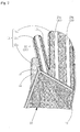
- Fig. 1 illustrates a glove-type power assist device seen from a back side, in which a fastener 12 is fastened.
- Fig. 2 illustrates the glove-type power assist device seen from the back side, in which the fastener 12 is opened.
- Fig. 3 illustrates the glove-type power assist device seen from a palm side.
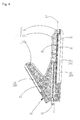
- Fig. 4 illustrates the glove-type power assist device seen from a thumb side, in which a forefinger inserting portion 11b is straightened.
- Fig. 5 illustrates the glove-type power assist device seen from a thumb side, in which a forefinger inserting portion 11b is bent.
- Fig. 1 illustrates a glove-type power assist device seen from a back side, in which a fastener 12 is fastened.
- Fig. 2 illustrates the glove-type power assist device seen from the back side, in which the fastener 12 is opened.
- Fig. 3 illustrates the glove-type power assist device seen from a palm side.
- FIG. 6 illustrates an expanding and contracting tube 20 laterally seen, which is in a contracting state (unbending state).
- Fig. 7 is a cross sectional view of the expanding and contracting tube 20 in the contracting state (unbending state) cut across a plane perpendicular to a center axis.
- Fig. 8 illustrates the expanding and contracting tube 20 laterally seen, which is in an expanding state (bending state).
- Fig. 9 is a cross sectional view of the expanding and contracting tube 20 in the expanding state (bending state) cut across a plane perpendicular to a center axis.
- the glove-type power assist device of the present embodiment includes a glove 10, the expanding and contracting tubes 20, and a fluid supplying member (not illustrated in Figures) as illustrated in Fig. 1 .
- the glove 10 is provided with finger inserting portions 11 for inserting fingers of a hand.
- the expanding and contracting tubes 20 are fixed to back side (dorsum manus side) of the finger inserting portions 11 of the glove 10. If a fluid is provided to the expanding and contracting tubes 20 from the fluid supplying unit to raise an inside pressure, the expanding and contracting tubes 20 change to a bending state illustrated in Fig. 8 from a straight state illustrated in Fig. 6 .
- the glove-type power assist device of the present embodiment assists folding motion of fingers as illustrated in Figs. 4 and 5 taking advantage of this operating characteristics of the expanding and contracting tubes 20. Concrete configurations of the expanding and contracting tubes 20 is explained later.
- Each expanding and contracting tube 20 of the glove-type power assist device of the present embodiment includes a tube main body 20a inflated by a pressure rise caused by a fluid provided to an inside thereof as illustrated in Fig. 6 , a fluid injecting pipe 20b for injecting the fluid into the tube main body 20a.
- the tube main body 20a includes an inner tube 20a1, an outer tube 20a2,a3 for covering an outer side of the inner tube 20a1.
- the inner tube 20a1 is made of an expandable and contractable material such as a rubber.
- the outer tube 20a2,a3 is configured by an expanding and contracting part 20a2 made of an expandable and contractable material such as a rubber, and an unexpanding and uncontracting part 20a3 made of an expandable and uncontractable material such as a cloth.
- the unexpanding and uncontracting part 20a3 is provided along a side of the tube main body 20a which is fixed to the finger inserting portion 11 of the glove 10. Therefore, a stretch of the expanding and contracting tube 20 along the longitudinal direction is prevented on a palm-side (the side of the expanding and contracting tube 20 which is fixed to the finger inserting portion 11) of the expanding and contracting tube 20.
- the glove-type power assist device of the present embodiment is provided with the unexpanding and uncontracting part 20a3 to bend as follows. Namely, as illustrated in Fig. 6 , in case a fluid is supplied to the expanding and contracting tubes 20 in a straight state (contracting state) and not in bending state, the expanding and contracting tubes 20 begin to bend to a palm-side (side on which the unexpanding and uncontracting portion 20a3 is provided) by expanding the back side (side on which the expanding and contracting portion 20a2 is provided) of the expanding and contracting tubes 20 more than the palm-side. This bending motions assist folding motions of fingers wearing the glove-type power assist device, as illustrated in Figs. 4 and 5 .
- the expanding and contracting tubes 20 begin to bend right after a provision of a fluid into the expanding and contracting tubes 20 to enhance a responsivity of the glove-type power assist device.
- the expanding and contracting tubes 20 expand their diameter as they shift from a contracting state (unbending state) to an expanding state (bending state). Namely, a size of expanding and contracting tubes 20 is small in a state a fluid is not supplied to the expanding and contracting tubes 20. Therefore, the glove-type power assist device is downsized when storing or carrying it. In the glove-type power assist device of the present embodiment, diameter of the expanding and contracting tube 20 is approximately 5mm in contracting states (unbending state) and approximately 10mm in expanding states (bending state).
- the fluid supplying member supplies a fluid to the expanding and contracting tubes 20.
- the fluid supplying member may be a member utilizing a compressor or a motor.
- the fluid supplying member includes a tank filled with a fluid to be supplied to expanding and contracting tubes 20, an on-off valve for opening and closing the tank, a valve controlling portion for controlling the opening or closing status of the on-off valve, and a portable battery (such as a battery or an electric cell) supplying a power to the on-off valve and the valve controlling portion.
- the fluid supplying member is downsized which is suitable for taking along, also vibrations and noises emitted from fluid supplying member are reduced, and also power consumption of the fluid supplying member is reduced.
- a fluid filled into the tank of the fluid supplying member may be either gas or liquid
- a liquefied carbon dioxide is preferably filled. By adapting this, a large amount of the liquefied carbon dioxide is provided to the expanding and contracting tubes 20 with the downsized tank.
- the liquefied carbon dioxide is easy to handle, safe and easy to obtain.
- Volume of the tank is 95ml in the glove-type power assist device of the present embodiment.
- the glove-type power assist device is able to perform grabbing motions approximately 200 times with this tank of said volume. This is sufficient volume considering that a person who often uses the glove-type power assist device conducts grabbing motions approximately 100 times a day.
- the finger inserting portions 11 of the glove 10 consist essentially of thumb inserting portion for inserting wearer's thumb, the forefinger inserting portion for inserting wearer's forefinger, the three fingers commonly inserting portion for inserting wearer's middle finger, ring finger and little finger, as illustrated in Fig. 1 . Therefore, an operability of the glove-type power assist device is enhanced and the glove-type power assist device is easily worn. In addition, costs required for the glove-type power assist device are reduced because the configuration is simplified. For example, if the number of finger inserting portions is five, five expanding and contracting tubes 20 are needed.
- the number of expanding and contracting tube 20 become three at the minimum by adapting the three fingers commonly inserting portion.
- one expanding and contracting tube for assisting a thumb 21 is provided on the thumb inserting portion 11a
- one expanding and contracting tube for assisting a forefinger 22 is provided on the forefinger inserting portion 11b
- two expanding and contracting tubes for assisting three fingers 23a,23b are provided on the three fingers commonly inserting portion 11c. Therefore, the number of the expanding and contracting tubes 20 adds up to four.
- a cutline is provided on the glove to cover a portion from a base of a forefinger on a thumb side to an opening for wearing the glove, as illustrated in Fig. 2 .
- a fastener 12 is provided for fastening the cutline. This makes it easy for those who have a handicap on fingers to wear the glove-type power assist device. Especially, a thumb is easily inserted into the thumb inserting portion 11a. Inserting the thumb into the thumb inserting portion 11a is most difficult.
- the glove-type power assist device of the present embodiment adapts a slide fastener as the fastener 12.
- Substantially whole of the glove 10 is configured by an elastic base material 13 having elasticity as illustrated in Fig. 1 . Portions made of the elastic base material 13 are cross hatched with smaller pitched hatching lines in Figs. 1 to 5 . Elastic cloths used as sport inner wears are preferably used as the elastic base material 13. The glove-type power assist device is worn without giving uncomfortable feelings by adapting this. Non-slip portions covered with non-slip sheets 14 are provided on a palm side than the side lines L1 ( Fig. 4 ) of the glove 10, as illustrated in Fig. 3 . Rubber sheets are preferably used as the non-slip sheets 14. Portions provided with the non-slip sheets 14 are cross hatched with larger pitched hatching lines in Figs. 1 to 5 .
- the non-slip sheets 14 In the glove-type power assist device of the present embodiment, only the unbending portions on a palm including the finger inserting portions not overlapping finger joints of a hand are covered with the non-slip sheets 14, as illustrated in Fig. 3 .
- bending portions overlapping the finger joints of the finger inserting portions 11 and provided on the palm-side than the side lines L1 are configured as blank portions 16 not covered with the non-slip sheets 14.
- the elastic base material 13 is exposed from the blank portions 16. This facilitates the finger inserting portions 11 to easily bend and enhances an operability and a wear comfort of the glove-type power assist device.
- unstretchable liner members 15 are fixed to portions, which are boundaries between the backside and the palm-side of the finger inserting portions 11 of the glove 10, along the side lines L1 of the finger inserting portions 11 as illustrated in Fig. 4 . Therefore, the portions along the side lines L1 of the finger inserting portions 11 has a configuration in which a stretch in longitudinal direction is prevented.
- the unstretchable liner members 15 are illustrated with bold lines in Figs. 1 to 5 .
- the unstretchable liner members 15 may be provided on one side of sides of either one of the finger inserting portions 11.
- the unstretchable liner members 15 are fixed along both of the left and right sides of the forefinger inserting portion 11b and along both of the left and right sides of the three fingers insertion portion 11c.
- the unstretchable liner members 15 are fixed in various manners.
- the unstretchable liner members 15 are fixed to the finger inserting portions 11 by sewing the stringlike unstretchable liner members 15 along the boundary between the elastic base material 13 and the non-slip sheets 14.
- Strings made of synthetic fibers are used as the unstretchable liner members 15. This makes bending centers of the finger inserting portions 11 and folding centers of wearer's finger joints more promptly and more securely correspond each other. Therefore, uncomfortable feelings given to a wearer is relieved.
- the glove-type power assist device of the present invention is not particularly limited. It is used for assisting a gripping power required for various motions in daily lives such as to hold a spoon, to hold a cup, to hold a pencil, also for rehabilitations for those who have handicaps on finger tips, trainings on how to use finger tips and stretches for preventing contracture. It is also used as a glove-type load applying device used for muscle trainings. Further, it is uses as a glove-type virtual experience device used for embodying virtual realities.
- the glove-type power assist device of the present invention smoothly assists finger motions of a hand of a wearer without giving a large strain on wearer's finger joints of the hand, and is easy to downsize and suitable for taking along, it is used for broad purposes as exemplified above.
- the glove-type power assist device assists folding motions of fingers of a hand is exemplified and explained so far.
- the glove-type power assist device is also used to assist stretching motions of fingers of a hand. Namely, if a fluid is discharged from the expanding and contracting tubes which are in bending state by being supplied with the fluid, the expanding and contracting tubes straighten from the bending state to assist stretching motions of fingers of a hand. However, in this case, large assisting power (operational ability) is not obtained in some cases.
- first expanding and contracting tube and second expanding and contracting tube are fixed along the back side of the common finger inserting portion, wherein the first expanding and contracting tube is configured so that a stretch in a longitudinal direction on a fixed side (palm-side) fixed with respect to the finger inserting portion is prevented (configured to have the same structure as the expanding and contracting tube 20 in Fig. 1 ), the second expanding and contracting tube is configured so that a stretch in the longitudinal direction on a side (back side) opposite to the fixed side fixed with respect to the finger inserting portion is prevented (configured to have the same structure as the expanding and contracting tube 20 in Fig.
- an expanding and contracting tube to be supplied with the fluid from the tank (fluid supplying member) is interchanged between the first expanding and contracting tube and the second expanding and contracting tube according to a motion to be executed by the glove-type power assist device.
- a fluid is supplied from the tank (fluid supplying member) to the first expanding and contracting tube while discharging a fluid from the second expanding and contracting tube.
- a fluid is supplied from the tank (fluid supplying member) to the second expanding and contracting tube while discharging a fluid from the first expanding and contracting tube.
Landscapes
- Health & Medical Sciences (AREA)
- Orthopedic Medicine & Surgery (AREA)
- General Health & Medical Sciences (AREA)
- Life Sciences & Earth Sciences (AREA)
- Physical Education & Sports Medicine (AREA)
- Engineering & Computer Science (AREA)
- Biophysics (AREA)
- Public Health (AREA)
- Veterinary Medicine (AREA)
- Animal Behavior & Ethology (AREA)
- General Engineering & Computer Science (AREA)
- Vascular Medicine (AREA)
- Nursing (AREA)
- Theoretical Computer Science (AREA)
- Biomedical Technology (AREA)
- Heart & Thoracic Surgery (AREA)
- Epidemiology (AREA)
- Rehabilitation Therapy (AREA)
- Human Computer Interaction (AREA)
- Physics & Mathematics (AREA)
- General Physics & Mathematics (AREA)
- Pain & Pain Management (AREA)
- Manipulator (AREA)
- Prostheses (AREA)
Abstract
Description
- The present invention relates to glove-type power assist device putted on a hand and assisting finger motions of wearer's hand.
- A shortage of care personnel becomes more serious as a birth rate falls and an aging population increases. The elderly caring the elderly, so called elder-to-elder caring, is often heard. Power assist devices become highly demanded, which relieve a physical strain on carers or support those who need care to be independent. Various power assist devices are proposed depending on parts to be assisted. Power assist devices for assisting folding motions of fingers of a hand is already known too.
- For example, Patent Document 1 discloses a power assist device (glove-type power assist device) including; tubular actuators being bent by raising an inside pressure, the inside pressure being raised by a provision of a fluid; a wearing body (glove) for fixing the actuators along finger joints of a hand.
- Patent Document 1 also discloses providing fluid receiving portions for the actuators along a longitudinal direction of the actuators, and providing preventing means preventing a stretch along the longitudinal direction on a side of the inside of the actuators.
- The glove-type power assist device of Patent Document 1 is not only suitable for assisting motions which accompany large displacements but also possible to alleviate a bound feeling given to wearers by having bending centers of the actuators and folding centers of finger joints of a hand corresponded. Although the bending centers of the actuator and the folding centers of finger joints of a hand correspond in the glove-type power assist device of Patent Document 1, since it undergoes the procedure that the bending centers of the actuators gradually approach to the folding centers of finger joints when the actuators deform, an uncomfortable feeling of which the wearers feel around the finger joints of the hand is not completely removed. The power assist glove-type device of Patent Document 1 is not necessarily easy to make it compact and portable.
- Patent Document 1: Japanese Patent Application Publication No.
2006-000294 Claims - The present invention provides a glove-type power assist device that is easy to use in daily lives, easy to wear, and does not give an unconfutable feeling when used. Specifically, the present invention provides a glove-type power assist device that does not undergo the procedure that the bending centers of the actuators gradually approach to the folding centers of finger joints as the actuators deform, but does undergo the procedure that the bending centers of the actuators correspond to the folding centers of finger joints from the beginning when actuators begin to bend to smoothly assist finger motions of a hand of a wearer without giving a large strain on the finger joints of the wearer and further to completely remove an uncomfortable feeling that the wearer feels around the finger joints of the hand. The present invention also provides the glove-type power assist device that is easy to make it compact and portable.
- Above said problems are solved by providing a glove-type power assist device. It includes a glove provided with finger inserting portions for inserting fingers of a hand; expanding and contracting tubes fixed to back side of the finger inserting portions of the glove, a stretch along a longitudinal direction is restricted on a side fixed to the finger inserting portions, and a fluid supplying member supplying a fluid to the expanding and contracting tubes. The expanding and contracting tubes are bent to a palm-side by expanding the back side of the expanding and contracting tubes more than the palm-side to assist a folding motion of fingers inserted into the finger inserting portions. Substantially whole of the glove is configured by an elastic base material. Side lines (virtual lines along centers of sides from which the sides of each finger inserting portion are divided into a back side and a palm side) are provided as boundaries between the back side and the palm-side of the finger inserting portions. Each side line has an unstretchable configuration (including not only a configuration in which it does not stretch at all but also a configuration in which it slightly stretches) in which a stretch to the longitudinal direction of the finger inserting portions is prevented so that the expanding and contracting tubes can bend at folding points of wearer's finger joints as centers.
- This enables for the expanding and contracting tubes to smoothly bend as the folding points of fingers joints as centers. Therefore, the wearer's finger motions are assisted without giving a large strain on the finger joints of the wearer of the glove-type power assist device. "Assist" is not only a concept which literally assisting a portion to be assisted (fingers of a hand) by applying a power along a forward direction with respect to a motion of the portion to be assisted but also includes a concept which assisting the portion to be assisted by applying a power along a reverse direction with respect to the motion of the portion to be assisted. The latter case is included in the concept of "assist" in order to make it clear that a glove-type load applying device used for rehabilitations or muscle trainings and a glove-type virtual experience device used for embodying virtual realities are included in a scope of the glove-type power assist device of the present invention.
- In the glove-type power assist device of the present invention, the side lines of the finger inserting portions are provided on the boundary between the back side and the palm-side, as descripted above. More precisely, it is preferable that the side lines are provided in the position where the side lines overlap with lines connecting the folding points of wearer's finger joints when the finger inserting portions are laterally seen. According to this, the bending centers of the expanding and contracting tubes more precisely correspond to the folding centers of the finger joints of the hand of the wearer. Concrete names of finger joints to which the side lines of the finger inserting portions are overlapped are DIP joint (distal interphalangeal joint), PIP joint (proximal interphalangeal joint), and MP joint (metacarpophalangeal joint) of a fore finger, a middle finger, a ring finger and a little finger; IP joint (interpharangeal joint) and MP joint (metacarpal phalangeal joint) of a thumb.
- In the glove-type power assisted device of the present invention, a concrete method for configuring the side lines unstretchable is not particularly limited. For example, the side lines of the finger inserting portions are made unstretchable configuration by fixing unstretchable liner members (including not only a configuration in which it does not stretch at all but also a configuration in which it slightly stretch) along the side lines of the finger inserting portions. As the unstretchable liner members, synthetic fibers such as polyester fibers or natural fibers such as cotton fibers are exemplified. The unstretchable liner members may be made of metal. The unstretchable liner members include not only strings but also band shaped objects. As methods for fixing the unstretchable liner members to the finger inserting portions, bonding or sewing is exemplified. In case the strings are used as the unstretchable liner members, the strings are to be sewed onto the finger inserting portions.
- Further, it is preferable that unbending portions not overlapping the finger joints of the finger inserting portions and provided on the palm-side than the side lines are configured as non-slip portions covered with non-slip sheets. At the same time, bending portions overlapping the finger joints of the finger inserting portions and provided on the palm-side than the side lines are configured as blank portions not covered with the non-slip sheets and exposing the elastic base material. According to this, an object is securely grabbed in wearing state without spoiling an operability of the glove-type power assist device. It is preferable that the blank portions are provided so that they are triangular shapes (triangles having bottoms on palm-side of the finger inserting portions and summits near the side lines) when they are laterally seen. The number of the blank portions corresponds to the number of joints of each finger. Namely, two blank portions (for IP joint (a first joint) and MP joint (a second joint)) are provided on the finger inserting portion (thumb inserting portion described later). Three blank portions (for DIP joint (a first joint), PIP joint (second joint) and MP joint (third joint)) are provided on other finger inserting portions (the fore finger inserting portion and the three fingers commonly inserting portion described later).
- Still further, according to the glove-type power assist device of the present invention, it is preferable that a cutline is provided on the glove to cover a portion from a base of a forefinger on a thumb side to an opening for wearing the glove, and a fastener is provided for fastening the cutline. This makes it easy to wear the glove-type power assist device. Especially, this makes it easy for those who have a handicap on fingers to wear the glove-type power assist device. In addition, this makes it easy to manufacture (sewing and others) the glove-type power assist device and maintain it. Various fasteners such as a slide fastener, a hook and loop fastener, and buttons and others are exemplified as the fastener for fastening the cutline. Among them, the slide fastener is preferably used as the fastener for fastening the cutline because it continuously fastens the cutline and it does not open unless it is intentionally slid.
- A shape of the glove (how the finger inserting portions divide) is not particularly limited in the glove-type power assist device of the present invention. Although the finger inserting portions of the glove consist essentially of a thumb inserting portion for inserting a thumb of a wearer, a forefinger inserting portion for inserting a forefinger, a middle finger inserting portion for inserting a middle finger, a ring finger inserting portion for inserting the ring finger, and a little finger inserting portion for inserting a little finger, it is preferable that the middle finger inserting portion, the ring finger inserting portion, and the little finger inserting portion are put together to one fingers inserting portion (three fingers commonly inserting portion). An operability of the glove-type power assist device is enhanced and the glove-type power assist device is easily worn, if the finger inserting portions of the glove are consist essentially of the thumb inserting portion, the forefinger inserting portion, and the three fingers commonly inserting portion. In addition, costs required for the glove-type power assist device are reduced because the number of the expanding and contracting tubes fixed to the three fingers commonly inserting portion is reduced. In case the forefinger inserting portion, the middle finger inserting portion, the ring finger inserting portion and the little finger inserting portion are put together to one fingers inserting portion (four fingers commonly inserting portion) and the finger inserting portions of the glove consist essentially of the thumb inserting portion and the four fingers commonly inserting portion, it is more advantageous in an ease to wear the glove-type power assist device and in costs required for it. However, it has a defect in that an operability of the glove-type power assist device is spoiled.
- Although a kind of the fluid supplying member is not particularly limited in the glove-type power assist device of the present invention, it is preferable that the fluid supplying member includes a tank whose capacity being equal to or below than 500ml and filled with a liquefied carbon dioxide, an on-off valve for opening and closing the tank, and a valve controlling portion for controlling the opening or closing status of the on-off valve. This makes the fluid supplying member compact and portable. Therefore, the glove-type power assist device is also become compact and portable. Volume of the tank is preferably equal to or below than 300ml, or is more preferably equal to or below than 200ml. On the other hand, if the volume is too small, liquefied carbon dioxide filled in the tank runs shortage in short time to often fill the liquefied carbon dioxide or to replace the tank. Therefore, the volume of tank is equal to or more than 10ml. The volume of the tank is preferably equal to or more than 30ml, or is more preferably equal to or more than 50ml.
- As descripted above, according to the present invention, the glove-type power assist device is provided in which an uncomfortable feeling is removed when using, which is easily worn and easily used in daily lives. Specifically, the present invention provides a glove-type power assist device that does not undergo the procedure that the bending centers of the actuators gradually approach to the folding centers of finger joints as the actuators deform, but does undergo the procedure that the folding centers of the actuators correspond to the bending centers of finger joints from the beginning when actuators begin to bend to smoothly assist finger motions of a hand of wearers without giving a large strain on the finger joints of the wearer and further to completely remove a uncomfortable feeling that the wearer feels around the finger joints of the hand. The present invention also provides the glove-type power assist device that is easy to make it compact and portable.
-
-
Fig. 1 illustrates a glove-type power assist device seen from a back side, in which a fastener is fastened; -
Fig. 2 illustrates the glove-type power assist device seen from the back side, in which the fastener is opened; -
Fig. 3 illustrates the glove-type power assist device seen from a palm side; -
Fig. 4 illustrates the glove-type power assist device seen from a thumb side, in which a forefinger inserting portion is straightened; -
Fig. 5 illustrates the glove-type power assist device seen from a thumb side, in which a forefinger inserting portion is folded; -
Fig. 6 illustrates an expanding and contracting tube laterally seen, which is in a contracting state (unbending state); -
Fig. 7 is a cross sectional view of the expanding and contracting tube in the contracting state (unbending state) cut across a plane perpendicular to a center axis; -
Fig. 8 illustrates the expanding and contracting tube laterally seen, which is in an expanding state (bending state); and -
Fig. 9 is a cross sectional view of the expanding and contracting tube in the expanding state (bending state) cut across a plane perpendicular to a center axis. - Preferable embodiments of the glove-type power assist device of the present invention with reference to Figures.
Fig. 1 illustrates a glove-type power assist device seen from a back side, in which afastener 12 is fastened.Fig. 2 illustrates the glove-type power assist device seen from the back side, in which thefastener 12 is opened.Fig. 3 illustrates the glove-type power assist device seen from a palm side.Fig. 4 illustrates the glove-type power assist device seen from a thumb side, in which aforefinger inserting portion 11b is straightened.Fig. 5 illustrates the glove-type power assist device seen from a thumb side, in which aforefinger inserting portion 11b is bent.Fig. 6 illustrates an expanding andcontracting tube 20 laterally seen, which is in a contracting state (unbending state).Fig. 7 is a cross sectional view of the expanding andcontracting tube 20 in the contracting state (unbending state) cut across a plane perpendicular to a center axis.Fig. 8 illustrates the expanding andcontracting tube 20 laterally seen, which is in an expanding state (bending state).Fig. 9 is a cross sectional view of the expanding andcontracting tube 20 in the expanding state (bending state) cut across a plane perpendicular to a center axis. - The glove-type power assist device of the present embodiment includes a
glove 10, the expanding andcontracting tubes 20, and a fluid supplying member (not illustrated in Figures) as illustrated inFig. 1 . Theglove 10 is provided withfinger inserting portions 11 for inserting fingers of a hand. The expanding andcontracting tubes 20 are fixed to back side (dorsum manus side) of thefinger inserting portions 11 of theglove 10. If a fluid is provided to the expanding andcontracting tubes 20 from the fluid supplying unit to raise an inside pressure, the expanding andcontracting tubes 20 change to a bending state illustrated inFig. 8 from a straight state illustrated inFig. 6 . The glove-type power assist device of the present embodiment assists folding motion of fingers as illustrated inFigs. 4 and5 taking advantage of this operating characteristics of the expanding andcontracting tubes 20. Concrete configurations of the expanding andcontracting tubes 20 is explained later. - Each expanding and
contracting tube 20 of the glove-type power assist device of the present embodiment includes a tubemain body 20a inflated by a pressure rise caused by a fluid provided to an inside thereof as illustrated inFig. 6 , afluid injecting pipe 20b for injecting the fluid into the tubemain body 20a. The tubemain body 20a includes an inner tube 20a1, an outer tube 20a2,a3 for covering an outer side of the inner tube 20a1. - Among the inner tube 20a1 and the outer tube 20a2,a3, the inner tube 20a1 is made of an expandable and contractable material such as a rubber. The outer tube 20a2,a3 is configured by an expanding and contracting part 20a2 made of an expandable and contractable material such as a rubber, and an unexpanding and uncontracting part 20a3 made of an expandable and uncontractable material such as a cloth. The unexpanding and uncontracting part 20a3 is provided along a side of the tube
main body 20a which is fixed to thefinger inserting portion 11 of theglove 10. Therefore, a stretch of the expanding andcontracting tube 20 along the longitudinal direction is prevented on a palm-side (the side of the expanding andcontracting tube 20 which is fixed to the finger inserting portion 11) of the expanding andcontracting tube 20. - The glove-type power assist device of the present embodiment is provided with the unexpanding and uncontracting part 20a3 to bend as follows. Namely, as illustrated in
Fig. 6 , in case a fluid is supplied to the expanding andcontracting tubes 20 in a straight state (contracting state) and not in bending state, the expanding andcontracting tubes 20 begin to bend to a palm-side (side on which the unexpanding and uncontracting portion 20a3 is provided) by expanding the back side (side on which the expanding and contracting portion 20a2 is provided) of the expanding andcontracting tubes 20 more than the palm-side. This bending motions assist folding motions of fingers wearing the glove-type power assist device, as illustrated inFigs. 4 and5 . - By the way, in the glove-type power assist device of the present embodiment, as illustrated in
Figs. 7 and9 , no gaps are provided between an inner periphery of the outer tube 20a2,20a3 and an outer periphery of the inner tube 20a1 to have the inner periphery of the outer tube 20a2,20a3 and the outer periphery of the inner tube 20a1 always closely contacted. Therefore, the expanding andcontracting tubes 20 begin to bend right after a provision of a fluid into the expanding andcontracting tubes 20 to enhance a responsivity of the glove-type power assist device. - The expanding and
contracting tubes 20 expand their diameter as they shift from a contracting state (unbending state) to an expanding state (bending state). Namely, a size of expanding andcontracting tubes 20 is small in a state a fluid is not supplied to the expanding andcontracting tubes 20. Therefore, the glove-type power assist device is downsized when storing or carrying it. In the glove-type power assist device of the present embodiment, diameter of the expanding andcontracting tube 20 is approximately 5mm in contracting states (unbending state) and approximately 10mm in expanding states (bending state). - The fluid supplying member supplies a fluid to the expanding and
contracting tubes 20. In the glove-type power assist device of the present embodiment, the fluid supplying member may be a member utilizing a compressor or a motor. However, in the glove-type power assist device of the present embodiment, the fluid supplying member includes a tank filled with a fluid to be supplied to expanding andcontracting tubes 20, an on-off valve for opening and closing the tank, a valve controlling portion for controlling the opening or closing status of the on-off valve, and a portable battery (such as a battery or an electric cell) supplying a power to the on-off valve and the valve controlling portion. By adapting this, the fluid supplying member is downsized which is suitable for taking along, also vibrations and noises emitted from fluid supplying member are reduced, and also power consumption of the fluid supplying member is reduced. - Although a fluid filled into the tank of the fluid supplying member may be either gas or liquid, a liquefied carbon dioxide is preferably filled. By adapting this, a large amount of the liquefied carbon dioxide is provided to the expanding and
contracting tubes 20 with the downsized tank. The liquefied carbon dioxide is easy to handle, safe and easy to obtain. Volume of the tank is 95ml in the glove-type power assist device of the present embodiment. The glove-type power assist device is able to perform grabbing motions approximately 200 times with this tank of said volume. This is sufficient volume considering that a person who often uses the glove-type power assist device conducts grabbing motions approximately 100 times a day. - In the glove-type power assist device of the present embodiment, the
finger inserting portions 11 of theglove 10 consist essentially of thumb inserting portion for inserting wearer's thumb, the forefinger inserting portion for inserting wearer's forefinger, the three fingers commonly inserting portion for inserting wearer's middle finger, ring finger and little finger, as illustrated inFig. 1 . Therefore, an operability of the glove-type power assist device is enhanced and the glove-type power assist device is easily worn. In addition, costs required for the glove-type power assist device are reduced because the configuration is simplified. For example, if the number of finger inserting portions is five, five expanding andcontracting tubes 20 are needed. However, the number of expanding andcontracting tube 20 become three at the minimum by adapting the three fingers commonly inserting portion. In the glove-type power assist device of the present embodiment, one expanding and contracting tube for assisting athumb 21 is provided on thethumb inserting portion 11a, one expanding and contracting tube for assisting aforefinger 22 is provided on theforefinger inserting portion 11b, and two expanding and contracting tubes for assisting threefingers portion 11c. Therefore, the number of the expanding andcontracting tubes 20 adds up to four. - In the glove-type power assist device of the present embodiment, a cutline is provided on the glove to cover a portion from a base of a forefinger on a thumb side to an opening for wearing the glove, as illustrated in
Fig. 2 . Afastener 12 is provided for fastening the cutline. This makes it easy for those who have a handicap on fingers to wear the glove-type power assist device. Especially, a thumb is easily inserted into thethumb inserting portion 11a. Inserting the thumb into thethumb inserting portion 11a is most difficult. The glove-type power assist device of the present embodiment adapts a slide fastener as thefastener 12. - Substantially whole of the
glove 10 is configured by anelastic base material 13 having elasticity as illustrated inFig. 1 . Portions made of theelastic base material 13 are cross hatched with smaller pitched hatching lines inFigs. 1 to 5 . Elastic cloths used as sport inner wears are preferably used as theelastic base material 13. The glove-type power assist device is worn without giving uncomfortable feelings by adapting this. Non-slip portions covered withnon-slip sheets 14 are provided on a palm side than the side lines L1 (Fig. 4 ) of theglove 10, as illustrated inFig. 3 . Rubber sheets are preferably used as thenon-slip sheets 14. Portions provided with thenon-slip sheets 14 are cross hatched with larger pitched hatching lines inFigs. 1 to 5 . - In the glove-type power assist device of the present embodiment, only the unbending portions on a palm including the finger inserting portions not overlapping finger joints of a hand are covered with the
non-slip sheets 14, as illustrated inFig. 3 . In other words, bending portions overlapping the finger joints of thefinger inserting portions 11 and provided on the palm-side than the side lines L1 are configured asblank portions 16 not covered with thenon-slip sheets 14. Theelastic base material 13 is exposed from theblank portions 16. This facilitates thefinger inserting portions 11 to easily bend and enhances an operability and a wear comfort of the glove-type power assist device. - In the glove-type power assist device of the present embodiment,
unstretchable liner members 15 are fixed to portions, which are boundaries between the backside and the palm-side of thefinger inserting portions 11 of theglove 10, along the side lines L1 of thefinger inserting portions 11 as illustrated inFig. 4 . Therefore, the portions along the side lines L1 of thefinger inserting portions 11 has a configuration in which a stretch in longitudinal direction is prevented. Theunstretchable liner members 15 are illustrated with bold lines inFigs. 1 to 5 . Theunstretchable liner members 15 may be provided on one side of sides of either one of thefinger inserting portions 11. In the glove-type power assist device of the present embodiment, as illustrated inFig. 1 , theunstretchable liner members 15 are fixed along both of the left and right sides of theforefinger inserting portion 11b and along both of the left and right sides of the threefingers insertion portion 11c. - The
unstretchable liner members 15 are fixed in various manners. In the glove-type power assist device of the present embodiment, theunstretchable liner members 15 are fixed to thefinger inserting portions 11 by sewing the stringlike unstretchableliner members 15 along the boundary between theelastic base material 13 and thenon-slip sheets 14. Strings made of synthetic fibers are used as theunstretchable liner members 15. This makes bending centers of thefinger inserting portions 11 and folding centers of wearer's finger joints more promptly and more securely correspond each other. Therefore, uncomfortable feelings given to a wearer is relieved. - Use of the glove-type power assist device of the present invention is not particularly limited. It is used for assisting a gripping power required for various motions in daily lives such as to hold a spoon, to hold a cup, to hold a pencil, also for rehabilitations for those who have handicaps on finger tips, trainings on how to use finger tips and stretches for preventing contracture. It is also used as a glove-type load applying device used for muscle trainings. Further, it is uses as a glove-type virtual experience device used for embodying virtual realities. Because the glove-type power assist device of the present invention smoothly assists finger motions of a hand of a wearer without giving a large strain on wearer's finger joints of the hand, and is easy to downsize and suitable for taking along, it is used for broad purposes as exemplified above.
- A case where the glove-type power assist device assists folding motions of fingers of a hand is exemplified and explained so far. The glove-type power assist device is also used to assist stretching motions of fingers of a hand. Namely, if a fluid is discharged from the expanding and contracting tubes which are in bending state by being supplied with the fluid, the expanding and contracting tubes straighten from the bending state to assist stretching motions of fingers of a hand. However, in this case, large assisting power (operational ability) is not obtained in some cases. Therefore, it is preferable that two kinds of expanding and contracting tubes (first expanding and contracting tube and second expanding and contracting tube) are fixed along the back side of the common finger inserting portion, wherein the first expanding and contracting tube is configured so that a stretch in a longitudinal direction on a fixed side (palm-side) fixed with respect to the finger inserting portion is prevented (configured to have the same structure as the expanding and
contracting tube 20 inFig. 1 ), the second expanding and contracting tube is configured so that a stretch in the longitudinal direction on a side (back side) opposite to the fixed side fixed with respect to the finger inserting portion is prevented (configured to have the same structure as the expanding andcontracting tube 20 inFig. 1 ), an expanding and contracting tube to be supplied with the fluid from the tank (fluid supplying member) is interchanged between the first expanding and contracting tube and the second expanding and contracting tube according to a motion to be executed by the glove-type power assist device. Concretely, in case bending motions are executed, a fluid is supplied from the tank (fluid supplying member) to the first expanding and contracting tube while discharging a fluid from the second expanding and contracting tube. In case stretching motions are executed, a fluid is supplied from the tank (fluid supplying member) to the second expanding and contracting tube while discharging a fluid from the first expanding and contracting tube. By adapting this, a large operational ability is obtained for stretching motions of fingers of a hand is assisted as well as for folding motions of the fingers of the hand. This configuration is preferably applicable to all purposes explained above. -
- 10
- Glove
- 11
- Finger inserting portion
- 11a
- Thumb inserting portion
- 11b
- Forefinger inserting portion
- 11c
- Three fingers commonly inserting portion
- 12
- Fastener
- 13
- Elastic base material
- 14
- Non-slip sheet
- 15
- Unstretchable liner member
- 16
- Blank portion
- 20
- Expanding and Contracting tube
- 20a
- Tube main body
- 20a1
- Inner tube
- 20a2
- Contracting part (outer tube)
- 20a3
- Unexpanding and uncontracting part (outer tube)
- 20b
- Fluid injecting pipe
- 21
- Expanding and contracting tube for assisting a thumb
- 22
- Expanding and contracting tube for assisting a forefinger
- 23a
- Expanding and contracting tubes for assisting three fingers
- 23b
- Expanding and contracting tubes for assisting three fingers
- L1
- Side line
Claims (7)
- A glove-type power assist device comprising:(a) a glove provided with finger inserting portions for inserting fingers of a hand;(b) expanding and contracting tubes fixed to back side of the finger inserting portions of the glove, a stretch along a longitudinal direction being restricted on a side fixed to the finger inserting portions, and(c) a fluid supplying member supplying a fluid to the expanding and contracting tubes;wherein the expanding and contracting tubes are bent to a palm-side by stretching the back side of the expanding and contracting tubes more than the palm-side to assist a folding motion of fingers inserted into the finger inserting portions,
wherein substantially whole of the glove is configured by an elastic base material, side lines are provided as boundaries between the back side and the palm-side of the finger inserting portions, the side lines have an unstretchable configuration in which a stretch to the longitudinal direction of the finger inserting portions is prevented so that the expanding and contracting tubes can bend at folding points of wearer's finger joints as centers. - The glove-type power assist device according to Claim 1, wherein the side lines are provided in the position where the side lines overlap with lines connecting the folding points of wearer's finger joints when the finger inserting portions are laterally seen.
- The glove-type power assist device according to Claim 1 or 2, wherein the side lines are made unstretchable configuration by fixing unstretchable liner members along the side lines of the finger inserting portions.
- The glove-type power assist device according to any one of Claims 1 to 3, wherein unbending portions not overlapping the finger joints of the finger inserting portions and provided on the palm-side than the side lines are configured as non-slip portions covered with non-slip sheets, bending portions overlapping the finger joints of the finger inserting portions and provided on the palm-side than the side lines are configured as blank portions not covered with the non-slip sheets and exposing the elastic base material.
- The glove-type power assist device according to any one of Claims 1 to 4, wherein a cutline is provided on the glove to cover a portion from a base of a forefinger on a thumb side to an opening for wearing the glove, a fastener is provided for fastening the cutline.
- The glove-type power assist device according to any one of Claims 1 to 5, wherein the finger inserting portions consist essentially of a thumb inserting portion for inserting wearer's thumb, a forefinger inserting portion for inserting wearer's forefinger, a three fingers commonly inserting portion for inserting wearer's middle finger, ring finger and little finger.
- The glove-type power assist device according to any one of Claims 1 to 6, wherein the fluid supplying member includes a tank whose capacity being equal to or below than 500ml and filled with a liquefied carbon dioxide, an on-off valve for opening and closing the tank, and a valve controlling portion for controlling the opening or closing status of the on-off valve.
Applications Claiming Priority (2)
| Application Number | Priority Date | Filing Date | Title |
|---|---|---|---|
| JP2011057791 | 2011-03-16 | ||
| PCT/JP2012/055694 WO2012124546A1 (en) | 2011-03-16 | 2012-03-06 | Glove-type power assist device |
Publications (4)
| Publication Number | Publication Date |
|---|---|
| EP2687191A1 true EP2687191A1 (en) | 2014-01-22 |
| EP2687191A4 EP2687191A4 (en) | 2014-10-15 |
| EP2687191B1 EP2687191B1 (en) | 2016-03-02 |
| EP2687191B8 EP2687191B8 (en) | 2016-05-11 |
Family
ID=46830621
Family Applications (1)
| Application Number | Title | Priority Date | Filing Date |
|---|---|---|---|
| EP12757696.5A Not-in-force EP2687191B8 (en) | 2011-03-16 | 2012-03-06 | Glove-type power assist device |
Country Status (5)
| Country | Link |
|---|---|
| EP (1) | EP2687191B8 (en) |
| JP (1) | JP5957786B2 (en) |
| CN (1) | CN103442667B (en) |
| DK (1) | DK2687191T3 (en) |
| WO (1) | WO2012124546A1 (en) |
Cited By (1)
| Publication number | Priority date | Publication date | Assignee | Title |
|---|---|---|---|---|
| WO2015191007A1 (en) * | 2014-06-12 | 2015-12-17 | National University Of Singapore | Actuator device, method and system for limb rehabilitation |
Families Citing this family (13)
| Publication number | Priority date | Publication date | Assignee | Title |
|---|---|---|---|---|
| US9492930B2 (en) * | 2013-10-18 | 2016-11-15 | President And Fellows Of Harvard College | Mechanically programmed soft actuators with conforming sleeves |
| US10184500B2 (en) * | 2013-10-29 | 2019-01-22 | President And Fellows Of Harvard College | Multi-segment reinforced actuators and applications |
| AU2015305311B2 (en) * | 2014-08-22 | 2020-04-23 | President And Fellows Of Harvard College | Sensors for soft robots and soft actuators |
| ES2911719T3 (en) | 2014-08-22 | 2022-05-20 | Harvard College | Soft robot with limited deformation flexible electronic shell |
| CN105161028A (en) * | 2015-09-25 | 2015-12-16 | 陈玉堂 | Potable recognition device for taking taxi |
| CN105212374A (en) * | 2015-11-04 | 2016-01-06 | 杨丽珍 | With the split type proof gloves of pocket |
| KR101814676B1 (en) * | 2016-07-25 | 2018-01-04 | 이동찬 | Wearable soft exoskeleton apparatus |
| US11129766B2 (en) | 2017-04-14 | 2021-09-28 | The Chinese University Of Hong Kong | Flexibly driven robotic hands |
| WO2019203732A1 (en) * | 2018-04-20 | 2019-10-24 | Roceso Technologies Private Limited | Wearable hand assistive device and system |
| WO2019223568A1 (en) * | 2018-05-23 | 2019-11-28 | The University Of Hong Kong | Soft robotic glove for rehabilitation |
| CN109953871B (en) * | 2019-04-11 | 2021-05-11 | 无锡市第九人民医院 | Finger sleeve for finger rehabilitation training by using air pressure distribution state |
| CN111228748B (en) * | 2020-01-13 | 2020-12-01 | 吉林大学 | ICU severe medical treatment is with hand constraint subassembly |
| CN111789745B (en) * | 2020-08-25 | 2022-11-15 | 河南科技大学 | Pneumatic rehabilitation glove |
Citations (1)
| Publication number | Priority date | Publication date | Assignee | Title |
|---|---|---|---|---|
| JP2006000294A (en) * | 2004-06-16 | 2006-01-05 | Toshirou Noritsugi | Mounting type power assist device |
Family Cites Families (5)
| Publication number | Priority date | Publication date | Assignee | Title |
|---|---|---|---|---|
| US4739692A (en) * | 1984-05-29 | 1988-04-26 | Fluidic Motion Corporation | Liquid contractility actuator |
| US6168634B1 (en) * | 1999-03-25 | 2001-01-02 | Geoffrey W. Schmitz | Hydraulically energized magnetorheological replicant muscle tissue and a system and a method for using and controlling same |
| JP3921916B2 (en) * | 2000-03-29 | 2007-05-30 | セイコーエプソン株式会社 | Body-worn muscle strength assist device |
| JP2004329490A (en) * | 2003-05-06 | 2004-11-25 | Osaka Industrial Promotion Organization | Tool and system for finger movement rehabilitation support |
| JP5472680B2 (en) * | 2009-04-09 | 2014-04-16 | 国立大学法人 筑波大学 | Wearable motion assist device |
-
2012
- 2012-03-06 CN CN201280013509.9A patent/CN103442667B/en not_active Expired - Fee Related
- 2012-03-06 DK DK12757696.5T patent/DK2687191T3/en active
- 2012-03-06 WO PCT/JP2012/055694 patent/WO2012124546A1/en active Application Filing
- 2012-03-06 EP EP12757696.5A patent/EP2687191B8/en not_active Not-in-force
- 2012-03-06 JP JP2013504671A patent/JP5957786B2/en not_active Expired - Fee Related
Patent Citations (1)
| Publication number | Priority date | Publication date | Assignee | Title |
|---|---|---|---|---|
| JP2006000294A (en) * | 2004-06-16 | 2006-01-05 | Toshirou Noritsugi | Mounting type power assist device |
Non-Patent Citations (5)
| Title |
|---|
| D. SASAKI ET AL: "Wearable power assist device for hand grasping using pneumatic artificial rubber muscle", RO-MAN 2004. 13TH IEEE INTERNATIONAL WORKSHOP ON ROBOT AND HUMAN INTERACTIVE COMMUNICATION (IEEE CATALOG NO.04TH8759), 1 January 2004 (2004-01-01), pages 655-660, XP055137590, DOI: 10.1109/ROMAN.2004.1374840 ISBN: 978-0-78-038570-2 * |
| KIMINORI TOYA ET AL: "Power-Assist Glove Operated by Predicting the Grasping Mode", JOURNAL OF SYSTEM DESIGN AND DYNAMICS, vol. 5, no. 1, 1 January 2011 (2011-01-01) , pages 94-108, XP055137491, DOI: 10.1299/jsdd.5.94 * |
| KYUNG-WON MOON ET AL: "Development of a Slim Haptic Glove Using McKibben Artificial Muscles", SICE-ICCAS 2006 INTERNATIONAL JOINT CONFERENCE, IEEE, PISCATAWAY, NJ, USA, 1 October 2006 (2006-10-01), pages 204-208, XP031050583, ISBN: 978-89-950038-4-8 * |
| See also references of WO2012124546A1 * |
| TOSHIRO NORITSUGU ET AL: "Power Assist Wear Driven with Pneumatic Rubber Artificial Muscles", 2008 15TH INTERNATIONAL CONFERENCE ON MECHATRONICS AND MACHINE VISION IN PRACTICE, 1 December 2008 (2008-12-01), pages 539-544, XP055137594, DOI: 10.1109/MMVIP.2008.4749589 ISBN: 978-1-42-443779-5 * |
Cited By (2)
| Publication number | Priority date | Publication date | Assignee | Title |
|---|---|---|---|---|
| WO2015191007A1 (en) * | 2014-06-12 | 2015-12-17 | National University Of Singapore | Actuator device, method and system for limb rehabilitation |
| GB2541623A (en) * | 2014-06-12 | 2017-02-22 | Nat Univ Singapore | Actuator device, method and system for limb rehabilitation |
Also Published As
| Publication number | Publication date |
|---|---|
| CN103442667B (en) | 2015-08-19 |
| JPWO2012124546A1 (en) | 2014-07-24 |
| EP2687191B1 (en) | 2016-03-02 |
| WO2012124546A1 (en) | 2012-09-20 |
| DK2687191T3 (en) | 2016-04-25 |
| CN103442667A (en) | 2013-12-11 |
| EP2687191B8 (en) | 2016-05-11 |
| JP5957786B2 (en) | 2016-07-27 |
| EP2687191A4 (en) | 2014-10-15 |
Similar Documents
| Publication | Publication Date | Title |
|---|---|---|
| EP2687191A1 (en) | Glove-type power assist device | |
| US10788058B2 (en) | Multi-segment reinforced actuators and applications | |
| JP6666375B2 (en) | Anti-fatigue and ergonomically improved medical / dental / practical gloves | |
| Polygerinos et al. | Soft robotic glove for combined assistance and at-home rehabilitation | |
| EP3632396B1 (en) | Knuckle rehabilitation device | |
| ES2652026T3 (en) | Reinforcement glove | |
| EP2409738A2 (en) | Glove with tensioned palm | |
| US6760923B1 (en) | Glove with flexible joints | |
| JP4564788B2 (en) | Wearable power assist device | |
| JP6279143B2 (en) | Joint motion assist device and method for mounting the joint motion assist device | |
| WO2011044500A2 (en) | Short stretch therapeutic compression device for the extremity | |
| CN108326828A (en) | Software pneumatic type joint assistance equipment | |
| EP2574320A1 (en) | Compression Sleeve | |
| CN208645318U (en) | Software pneumatic type joint assistance equipment | |
| CN219250832U (en) | Pneumatic rehabilitation glove | |
| CN103892948A (en) | Clamping plate and manufacturing method thereof | |
| WO2020202418A1 (en) | Joint motion assistance device and method for mounting joint motion assistance device | |
| US20230321814A1 (en) | Hand exoskeleton for rehabilitation and assistance of hand motor functions | |
| CN203829106U (en) | Hand rehabilitation and correction support | |
| CN111991184A (en) | Rigidity-variable soft pneumatic rehabilitation hand | |
| JP4969622B2 (en) | Protector | |
| JP2009062649A (en) | Hand protector and finger protector | |
| KR102485961B1 (en) | Rehabilitation exercise gloves | |
| EP3597157B1 (en) | An orthosis and kit of parts | |
| CN219071114U (en) | Line drives recovered gloves and helps ware of putting on |
Legal Events
| Date | Code | Title | Description |
|---|---|---|---|
| PUAI | Public reference made under article 153(3) epc to a published international application that has entered the european phase |
Free format text: ORIGINAL CODE: 0009012 |
|
| 17P | Request for examination filed |
Effective date: 20131014 |
|
| AK | Designated contracting states |
Kind code of ref document: A1 Designated state(s): AL AT BE BG CH CY CZ DE DK EE ES FI FR GB GR HR HU IE IS IT LI LT LU LV MC MK MT NL NO PL PT RO RS SE SI SK SM TR |
|
| DAX | Request for extension of the european patent (deleted) | ||
| A4 | Supplementary search report drawn up and despatched |
Effective date: 20140916 |
|
| RIC1 | Information provided on ipc code assigned before grant |
Ipc: F15B 15/10 20060101ALI20140910BHEP Ipc: B25J 9/14 20060101ALI20140910BHEP Ipc: A61F 2/56 20060101AFI20140910BHEP Ipc: G06F 3/01 20060101ALI20140910BHEP Ipc: A61F 5/01 20060101ALI20140910BHEP Ipc: A61F 2/68 20060101ALI20140910BHEP Ipc: A63B 23/16 20060101ALI20140910BHEP |
|
| GRAP | Despatch of communication of intention to grant a patent |
Free format text: ORIGINAL CODE: EPIDOSNIGR1 |
|
| INTG | Intention to grant announced |
Effective date: 20150917 |
|
| RIN1 | Information on inventor provided before grant (corrected) |
Inventor name: OGAWA, KAZUNORI Inventor name: SASAKI, DAISUKE Inventor name: IKEDA, TOMOHIRO Inventor name: NORITSUGU, TOSHIRO |
|
| GRAS | Grant fee paid |
Free format text: ORIGINAL CODE: EPIDOSNIGR3 |
|
| GRAA | (expected) grant |
Free format text: ORIGINAL CODE: 0009210 |
|
| AK | Designated contracting states |
Kind code of ref document: B1 Designated state(s): AL AT BE BG CH CY CZ DE DK EE ES FI FR GB GR HR HU IE IS IT LI LT LU LV MC MK MT NL NO PL PT RO RS SE SI SK SM TR |
|
| REG | Reference to a national code |
Ref country code: GB Ref legal event code: FG4D |
|
| REG | Reference to a national code |
Ref country code: FR Ref legal event code: PLFP Year of fee payment: 5 |
|
| REG | Reference to a national code |
Ref country code: AT Ref legal event code: REF Ref document number: 777464 Country of ref document: AT Kind code of ref document: T Effective date: 20160315 Ref country code: CH Ref legal event code: EP |
|
| REG | Reference to a national code |
Ref country code: IE Ref legal event code: FG4D |
|
| RAP2 | Party data changed (patent owner data changed or rights of a patent transferred) |
Owner name: DAIYA INDUSTRY CO., LTD. Owner name: NATIONAL UNIVERSITY CORPORATION OKAYAMA UNIVERSITY |
|
| REG | Reference to a national code |
Ref country code: DE Ref legal event code: R096 Ref document number: 602012015237 Country of ref document: DE |
|
| REG | Reference to a national code |
Ref country code: DK Ref legal event code: T3 Effective date: 20160419 |
|
| REG | Reference to a national code |
Ref country code: NL Ref legal event code: MP Effective date: 20160302 |
|
| REG | Reference to a national code |
Ref country code: LT Ref legal event code: MG4D |
|
| REG | Reference to a national code |
Ref country code: AT Ref legal event code: MK05 Ref document number: 777464 Country of ref document: AT Kind code of ref document: T Effective date: 20160302 |
|
| PG25 | Lapsed in a contracting state [announced via postgrant information from national office to epo] |
Ref country code: FI Free format text: LAPSE BECAUSE OF FAILURE TO SUBMIT A TRANSLATION OF THE DESCRIPTION OR TO PAY THE FEE WITHIN THE PRESCRIBED TIME-LIMIT Effective date: 20160302 Ref country code: NO Free format text: LAPSE BECAUSE OF FAILURE TO SUBMIT A TRANSLATION OF THE DESCRIPTION OR TO PAY THE FEE WITHIN THE PRESCRIBED TIME-LIMIT Effective date: 20160602 Ref country code: GR Free format text: LAPSE BECAUSE OF FAILURE TO SUBMIT A TRANSLATION OF THE DESCRIPTION OR TO PAY THE FEE WITHIN THE PRESCRIBED TIME-LIMIT Effective date: 20160603 Ref country code: ES Free format text: LAPSE BECAUSE OF FAILURE TO SUBMIT A TRANSLATION OF THE DESCRIPTION OR TO PAY THE FEE WITHIN THE PRESCRIBED TIME-LIMIT Effective date: 20160302 Ref country code: HR Free format text: LAPSE BECAUSE OF FAILURE TO SUBMIT A TRANSLATION OF THE DESCRIPTION OR TO PAY THE FEE WITHIN THE PRESCRIBED TIME-LIMIT Effective date: 20160302 |
|
| PG25 | Lapsed in a contracting state [announced via postgrant information from national office to epo] |
Ref country code: LT Free format text: LAPSE BECAUSE OF FAILURE TO SUBMIT A TRANSLATION OF THE DESCRIPTION OR TO PAY THE FEE WITHIN THE PRESCRIBED TIME-LIMIT Effective date: 20160302 Ref country code: SE Free format text: LAPSE BECAUSE OF FAILURE TO SUBMIT A TRANSLATION OF THE DESCRIPTION OR TO PAY THE FEE WITHIN THE PRESCRIBED TIME-LIMIT Effective date: 20160302 Ref country code: BE Free format text: LAPSE BECAUSE OF NON-PAYMENT OF DUE FEES Effective date: 20160331 Ref country code: RS Free format text: LAPSE BECAUSE OF FAILURE TO SUBMIT A TRANSLATION OF THE DESCRIPTION OR TO PAY THE FEE WITHIN THE PRESCRIBED TIME-LIMIT Effective date: 20160302 Ref country code: PL Free format text: LAPSE BECAUSE OF FAILURE TO SUBMIT A TRANSLATION OF THE DESCRIPTION OR TO PAY THE FEE WITHIN THE PRESCRIBED TIME-LIMIT Effective date: 20160302 Ref country code: LV Free format text: LAPSE BECAUSE OF FAILURE TO SUBMIT A TRANSLATION OF THE DESCRIPTION OR TO PAY THE FEE WITHIN THE PRESCRIBED TIME-LIMIT Effective date: 20160302 Ref country code: NL Free format text: LAPSE BECAUSE OF FAILURE TO SUBMIT A TRANSLATION OF THE DESCRIPTION OR TO PAY THE FEE WITHIN THE PRESCRIBED TIME-LIMIT Effective date: 20160302 Ref country code: AT Free format text: LAPSE BECAUSE OF FAILURE TO SUBMIT A TRANSLATION OF THE DESCRIPTION OR TO PAY THE FEE WITHIN THE PRESCRIBED TIME-LIMIT Effective date: 20160302 |
|
| PG25 | Lapsed in a contracting state [announced via postgrant information from national office to epo] |
Ref country code: EE Free format text: LAPSE BECAUSE OF FAILURE TO SUBMIT A TRANSLATION OF THE DESCRIPTION OR TO PAY THE FEE WITHIN THE PRESCRIBED TIME-LIMIT Effective date: 20160302 Ref country code: IS Free format text: LAPSE BECAUSE OF FAILURE TO SUBMIT A TRANSLATION OF THE DESCRIPTION OR TO PAY THE FEE WITHIN THE PRESCRIBED TIME-LIMIT Effective date: 20160702 |
|
| REG | Reference to a national code |
Ref country code: CH Ref legal event code: PL |
|
| PG25 | Lapsed in a contracting state [announced via postgrant information from national office to epo] |
Ref country code: RO Free format text: LAPSE BECAUSE OF FAILURE TO SUBMIT A TRANSLATION OF THE DESCRIPTION OR TO PAY THE FEE WITHIN THE PRESCRIBED TIME-LIMIT Effective date: 20160302 Ref country code: PT Free format text: LAPSE BECAUSE OF FAILURE TO SUBMIT A TRANSLATION OF THE DESCRIPTION OR TO PAY THE FEE WITHIN THE PRESCRIBED TIME-LIMIT Effective date: 20160704 Ref country code: SK Free format text: LAPSE BECAUSE OF FAILURE TO SUBMIT A TRANSLATION OF THE DESCRIPTION OR TO PAY THE FEE WITHIN THE PRESCRIBED TIME-LIMIT Effective date: 20160302 Ref country code: SM Free format text: LAPSE BECAUSE OF FAILURE TO SUBMIT A TRANSLATION OF THE DESCRIPTION OR TO PAY THE FEE WITHIN THE PRESCRIBED TIME-LIMIT Effective date: 20160302 Ref country code: CZ Free format text: LAPSE BECAUSE OF FAILURE TO SUBMIT A TRANSLATION OF THE DESCRIPTION OR TO PAY THE FEE WITHIN THE PRESCRIBED TIME-LIMIT Effective date: 20160302 |
|
| REG | Reference to a national code |
Ref country code: DE Ref legal event code: R097 Ref document number: 602012015237 Country of ref document: DE |
|
| REG | Reference to a national code |
Ref country code: IE Ref legal event code: MM4A |
|
| PG25 | Lapsed in a contracting state [announced via postgrant information from national office to epo] |
Ref country code: BE Free format text: LAPSE BECAUSE OF FAILURE TO SUBMIT A TRANSLATION OF THE DESCRIPTION OR TO PAY THE FEE WITHIN THE PRESCRIBED TIME-LIMIT Effective date: 20160302 |
|
| PLBE | No opposition filed within time limit |
Free format text: ORIGINAL CODE: 0009261 |
|
| STAA | Information on the status of an ep patent application or granted ep patent |
Free format text: STATUS: NO OPPOSITION FILED WITHIN TIME LIMIT |
|
| PG25 | Lapsed in a contracting state [announced via postgrant information from national office to epo] |
Ref country code: CH Free format text: LAPSE BECAUSE OF NON-PAYMENT OF DUE FEES Effective date: 20160331 Ref country code: LI Free format text: LAPSE BECAUSE OF NON-PAYMENT OF DUE FEES Effective date: 20160331 Ref country code: IE Free format text: LAPSE BECAUSE OF NON-PAYMENT OF DUE FEES Effective date: 20160306 |
|
| REG | Reference to a national code |
Ref country code: FR Ref legal event code: PLFP Year of fee payment: 6 |
|
| 26N | No opposition filed |
Effective date: 20161205 |
|
| PG25 | Lapsed in a contracting state [announced via postgrant information from national office to epo] |
Ref country code: BG Free format text: LAPSE BECAUSE OF FAILURE TO SUBMIT A TRANSLATION OF THE DESCRIPTION OR TO PAY THE FEE WITHIN THE PRESCRIBED TIME-LIMIT Effective date: 20160602 Ref country code: SI Free format text: LAPSE BECAUSE OF FAILURE TO SUBMIT A TRANSLATION OF THE DESCRIPTION OR TO PAY THE FEE WITHIN THE PRESCRIBED TIME-LIMIT Effective date: 20160302 |
|
| PG25 | Lapsed in a contracting state [announced via postgrant information from national office to epo] |
Ref country code: MT Free format text: LAPSE BECAUSE OF FAILURE TO SUBMIT A TRANSLATION OF THE DESCRIPTION OR TO PAY THE FEE WITHIN THE PRESCRIBED TIME-LIMIT Effective date: 20160302 |
|
| REG | Reference to a national code |
Ref country code: FR Ref legal event code: PLFP Year of fee payment: 7 |
|
| PG25 | Lapsed in a contracting state [announced via postgrant information from national office to epo] |
Ref country code: HU Free format text: LAPSE BECAUSE OF FAILURE TO SUBMIT A TRANSLATION OF THE DESCRIPTION OR TO PAY THE FEE WITHIN THE PRESCRIBED TIME-LIMIT; INVALID AB INITIO Effective date: 20120306 Ref country code: CY Free format text: LAPSE BECAUSE OF FAILURE TO SUBMIT A TRANSLATION OF THE DESCRIPTION OR TO PAY THE FEE WITHIN THE PRESCRIBED TIME-LIMIT Effective date: 20160302 |
|
| PG25 | Lapsed in a contracting state [announced via postgrant information from national office to epo] |
Ref country code: TR Free format text: LAPSE BECAUSE OF FAILURE TO SUBMIT A TRANSLATION OF THE DESCRIPTION OR TO PAY THE FEE WITHIN THE PRESCRIBED TIME-LIMIT Effective date: 20160302 Ref country code: MC Free format text: LAPSE BECAUSE OF FAILURE TO SUBMIT A TRANSLATION OF THE DESCRIPTION OR TO PAY THE FEE WITHIN THE PRESCRIBED TIME-LIMIT Effective date: 20160302 Ref country code: MK Free format text: LAPSE BECAUSE OF FAILURE TO SUBMIT A TRANSLATION OF THE DESCRIPTION OR TO PAY THE FEE WITHIN THE PRESCRIBED TIME-LIMIT Effective date: 20160302 Ref country code: LU Free format text: LAPSE BECAUSE OF NON-PAYMENT OF DUE FEES Effective date: 20160306 Ref country code: MT Free format text: LAPSE BECAUSE OF FAILURE TO SUBMIT A TRANSLATION OF THE DESCRIPTION OR TO PAY THE FEE WITHIN THE PRESCRIBED TIME-LIMIT Effective date: 20160331 |
|
| PG25 | Lapsed in a contracting state [announced via postgrant information from national office to epo] |
Ref country code: AL Free format text: LAPSE BECAUSE OF FAILURE TO SUBMIT A TRANSLATION OF THE DESCRIPTION OR TO PAY THE FEE WITHIN THE PRESCRIBED TIME-LIMIT Effective date: 20160302 |
|
| REG | Reference to a national code |
Ref country code: DE Ref legal event code: R082 Ref document number: 602012015237 Country of ref document: DE Representative=s name: MUELLER-BORE & PARTNER PATENTANWAELTE PARTG MB, DE Ref country code: DE Ref legal event code: R081 Ref document number: 602012015237 Country of ref document: DE Owner name: NATIONAL UNIVERSITY CORPORATION OKAYAMA UNIVER, JP Free format text: FORMER OWNER: NATIONAL UNIVERSITY CORPORATION OKAYAMA UNIVERSITY, OKAYAMA-SHI, OKAYAMA, JP Ref country code: DE Ref legal event code: R081 Ref document number: 602012015237 Country of ref document: DE Owner name: DAIYA HOLDINGS CO., LTD., JP Free format text: FORMER OWNER: NATIONAL UNIVERSITY CORPORATION OKAYAMA UNIVERSITY, OKAYAMA-SHI, OKAYAMA, JP |
|
| PGFP | Annual fee paid to national office [announced via postgrant information from national office to epo] |
Ref country code: FR Payment date: 20210326 Year of fee payment: 10 Ref country code: IT Payment date: 20210323 Year of fee payment: 10 |
|
| PGFP | Annual fee paid to national office [announced via postgrant information from national office to epo] |
Ref country code: GB Payment date: 20210326 Year of fee payment: 10 |
|
| PGFP | Annual fee paid to national office [announced via postgrant information from national office to epo] |
Ref country code: DE Payment date: 20210329 Year of fee payment: 10 |
|
| PGFP | Annual fee paid to national office [announced via postgrant information from national office to epo] |
Ref country code: DK Payment date: 20220324 Year of fee payment: 11 |
|
| REG | Reference to a national code |
Ref country code: DE Ref legal event code: R119 Ref document number: 602012015237 Country of ref document: DE |
|
| GBPC | Gb: european patent ceased through non-payment of renewal fee |
Effective date: 20220306 |
|
| PG25 | Lapsed in a contracting state [announced via postgrant information from national office to epo] |
Ref country code: GB Free format text: LAPSE BECAUSE OF NON-PAYMENT OF DUE FEES Effective date: 20220306 Ref country code: FR Free format text: LAPSE BECAUSE OF NON-PAYMENT OF DUE FEES Effective date: 20220331 Ref country code: DE Free format text: LAPSE BECAUSE OF NON-PAYMENT OF DUE FEES Effective date: 20221001 |
|
| PG25 | Lapsed in a contracting state [announced via postgrant information from national office to epo] |
Ref country code: IT Free format text: LAPSE BECAUSE OF NON-PAYMENT OF DUE FEES Effective date: 20220306 |
|
| REG | Reference to a national code |
Ref country code: DK Ref legal event code: EBP Effective date: 20230331 |
|
| PG25 | Lapsed in a contracting state [announced via postgrant information from national office to epo] |
Ref country code: DK Free format text: LAPSE BECAUSE OF NON-PAYMENT OF DUE FEES Effective date: 20230331 |