WO2012124481A1 - Module de batterie - Google Patents
Module de batterie Download PDFInfo
- Publication number
- WO2012124481A1 WO2012124481A1 PCT/JP2012/055124 JP2012055124W WO2012124481A1 WO 2012124481 A1 WO2012124481 A1 WO 2012124481A1 JP 2012055124 W JP2012055124 W JP 2012055124W WO 2012124481 A1 WO2012124481 A1 WO 2012124481A1
- Authority
- WO
- WIPO (PCT)
- Prior art keywords
- battery module
- battery
- module
- vehicle
- modules
- Prior art date
Links
Images


Classifications
-
- H—ELECTRICITY
- H01—ELECTRIC ELEMENTS
- H01M—PROCESSES OR MEANS, e.g. BATTERIES, FOR THE DIRECT CONVERSION OF CHEMICAL ENERGY INTO ELECTRICAL ENERGY
- H01M10/00—Secondary cells; Manufacture thereof
- H01M10/60—Heating or cooling; Temperature control
- H01M10/64—Heating or cooling; Temperature control characterised by the shape of the cells
- H01M10/647—Prismatic or flat cells, e.g. pouch cells
-
- B—PERFORMING OPERATIONS; TRANSPORTING
- B60—VEHICLES IN GENERAL
- B60L—PROPULSION OF ELECTRICALLY-PROPELLED VEHICLES; SUPPLYING ELECTRIC POWER FOR AUXILIARY EQUIPMENT OF ELECTRICALLY-PROPELLED VEHICLES; ELECTRODYNAMIC BRAKE SYSTEMS FOR VEHICLES IN GENERAL; MAGNETIC SUSPENSION OR LEVITATION FOR VEHICLES; MONITORING OPERATING VARIABLES OF ELECTRICALLY-PROPELLED VEHICLES; ELECTRIC SAFETY DEVICES FOR ELECTRICALLY-PROPELLED VEHICLES
- B60L50/00—Electric propulsion with power supplied within the vehicle
- B60L50/50—Electric propulsion with power supplied within the vehicle using propulsion power supplied by batteries or fuel cells
- B60L50/60—Electric propulsion with power supplied within the vehicle using propulsion power supplied by batteries or fuel cells using power supplied by batteries
- B60L50/64—Constructional details of batteries specially adapted for electric vehicles
-
- B—PERFORMING OPERATIONS; TRANSPORTING
- B60—VEHICLES IN GENERAL
- B60L—PROPULSION OF ELECTRICALLY-PROPELLED VEHICLES; SUPPLYING ELECTRIC POWER FOR AUXILIARY EQUIPMENT OF ELECTRICALLY-PROPELLED VEHICLES; ELECTRODYNAMIC BRAKE SYSTEMS FOR VEHICLES IN GENERAL; MAGNETIC SUSPENSION OR LEVITATION FOR VEHICLES; MONITORING OPERATING VARIABLES OF ELECTRICALLY-PROPELLED VEHICLES; ELECTRIC SAFETY DEVICES FOR ELECTRICALLY-PROPELLED VEHICLES
- B60L50/00—Electric propulsion with power supplied within the vehicle
- B60L50/50—Electric propulsion with power supplied within the vehicle using propulsion power supplied by batteries or fuel cells
- B60L50/60—Electric propulsion with power supplied within the vehicle using propulsion power supplied by batteries or fuel cells using power supplied by batteries
- B60L50/66—Arrangements of batteries
-
- H—ELECTRICITY
- H01—ELECTRIC ELEMENTS
- H01M—PROCESSES OR MEANS, e.g. BATTERIES, FOR THE DIRECT CONVERSION OF CHEMICAL ENERGY INTO ELECTRICAL ENERGY
- H01M10/00—Secondary cells; Manufacture thereof
- H01M10/60—Heating or cooling; Temperature control
- H01M10/61—Types of temperature control
- H01M10/615—Heating or keeping warm
-
- H—ELECTRICITY
- H01—ELECTRIC ELEMENTS
- H01M—PROCESSES OR MEANS, e.g. BATTERIES, FOR THE DIRECT CONVERSION OF CHEMICAL ENERGY INTO ELECTRICAL ENERGY
- H01M10/00—Secondary cells; Manufacture thereof
- H01M10/60—Heating or cooling; Temperature control
- H01M10/62—Heating or cooling; Temperature control specially adapted for specific applications
- H01M10/625—Vehicles
-
- H—ELECTRICITY
- H01—ELECTRIC ELEMENTS
- H01M—PROCESSES OR MEANS, e.g. BATTERIES, FOR THE DIRECT CONVERSION OF CHEMICAL ENERGY INTO ELECTRICAL ENERGY
- H01M10/00—Secondary cells; Manufacture thereof
- H01M10/60—Heating or cooling; Temperature control
- H01M10/65—Means for temperature control structurally associated with the cells
- H01M10/657—Means for temperature control structurally associated with the cells by electric or electromagnetic means
- H01M10/6571—Resistive heaters
-
- H—ELECTRICITY
- H01—ELECTRIC ELEMENTS
- H01M—PROCESSES OR MEANS, e.g. BATTERIES, FOR THE DIRECT CONVERSION OF CHEMICAL ENERGY INTO ELECTRICAL ENERGY
- H01M50/00—Constructional details or processes of manufacture of the non-active parts of electrochemical cells other than fuel cells, e.g. hybrid cells
- H01M50/20—Mountings; Secondary casings or frames; Racks, modules or packs; Suspension devices; Shock absorbers; Transport or carrying devices; Holders
- H01M50/204—Racks, modules or packs for multiple batteries or multiple cells
- H01M50/207—Racks, modules or packs for multiple batteries or multiple cells characterised by their shape
- H01M50/209—Racks, modules or packs for multiple batteries or multiple cells characterised by their shape adapted for prismatic or rectangular cells
-
- H—ELECTRICITY
- H01—ELECTRIC ELEMENTS
- H01M—PROCESSES OR MEANS, e.g. BATTERIES, FOR THE DIRECT CONVERSION OF CHEMICAL ENERGY INTO ELECTRICAL ENERGY
- H01M50/00—Constructional details or processes of manufacture of the non-active parts of electrochemical cells other than fuel cells, e.g. hybrid cells
- H01M50/20—Mountings; Secondary casings or frames; Racks, modules or packs; Suspension devices; Shock absorbers; Transport or carrying devices; Holders
- H01M50/249—Mountings; Secondary casings or frames; Racks, modules or packs; Suspension devices; Shock absorbers; Transport or carrying devices; Holders specially adapted for aircraft or vehicles, e.g. cars or trains
-
- B—PERFORMING OPERATIONS; TRANSPORTING
- B60—VEHICLES IN GENERAL
- B60L—PROPULSION OF ELECTRICALLY-PROPELLED VEHICLES; SUPPLYING ELECTRIC POWER FOR AUXILIARY EQUIPMENT OF ELECTRICALLY-PROPELLED VEHICLES; ELECTRODYNAMIC BRAKE SYSTEMS FOR VEHICLES IN GENERAL; MAGNETIC SUSPENSION OR LEVITATION FOR VEHICLES; MONITORING OPERATING VARIABLES OF ELECTRICALLY-PROPELLED VEHICLES; ELECTRIC SAFETY DEVICES FOR ELECTRICALLY-PROPELLED VEHICLES
- B60L1/00—Supplying electric power to auxiliary equipment of vehicles
- B60L1/02—Supplying electric power to auxiliary equipment of vehicles to electric heating circuits
-
- B—PERFORMING OPERATIONS; TRANSPORTING
- B60—VEHICLES IN GENERAL
- B60L—PROPULSION OF ELECTRICALLY-PROPELLED VEHICLES; SUPPLYING ELECTRIC POWER FOR AUXILIARY EQUIPMENT OF ELECTRICALLY-PROPELLED VEHICLES; ELECTRODYNAMIC BRAKE SYSTEMS FOR VEHICLES IN GENERAL; MAGNETIC SUSPENSION OR LEVITATION FOR VEHICLES; MONITORING OPERATING VARIABLES OF ELECTRICALLY-PROPELLED VEHICLES; ELECTRIC SAFETY DEVICES FOR ELECTRICALLY-PROPELLED VEHICLES
- B60L2240/00—Control parameters of input or output; Target parameters
- B60L2240/40—Drive Train control parameters
- B60L2240/54—Drive Train control parameters related to batteries
- B60L2240/545—Temperature
-
- B—PERFORMING OPERATIONS; TRANSPORTING
- B60—VEHICLES IN GENERAL
- B60L—PROPULSION OF ELECTRICALLY-PROPELLED VEHICLES; SUPPLYING ELECTRIC POWER FOR AUXILIARY EQUIPMENT OF ELECTRICALLY-PROPELLED VEHICLES; ELECTRODYNAMIC BRAKE SYSTEMS FOR VEHICLES IN GENERAL; MAGNETIC SUSPENSION OR LEVITATION FOR VEHICLES; MONITORING OPERATING VARIABLES OF ELECTRICALLY-PROPELLED VEHICLES; ELECTRIC SAFETY DEVICES FOR ELECTRICALLY-PROPELLED VEHICLES
- B60L50/00—Electric propulsion with power supplied within the vehicle
- B60L50/50—Electric propulsion with power supplied within the vehicle using propulsion power supplied by batteries or fuel cells
- B60L50/51—Electric propulsion with power supplied within the vehicle using propulsion power supplied by batteries or fuel cells characterised by AC-motors
-
- B—PERFORMING OPERATIONS; TRANSPORTING
- B60—VEHICLES IN GENERAL
- B60L—PROPULSION OF ELECTRICALLY-PROPELLED VEHICLES; SUPPLYING ELECTRIC POWER FOR AUXILIARY EQUIPMENT OF ELECTRICALLY-PROPELLED VEHICLES; ELECTRODYNAMIC BRAKE SYSTEMS FOR VEHICLES IN GENERAL; MAGNETIC SUSPENSION OR LEVITATION FOR VEHICLES; MONITORING OPERATING VARIABLES OF ELECTRICALLY-PROPELLED VEHICLES; ELECTRIC SAFETY DEVICES FOR ELECTRICALLY-PROPELLED VEHICLES
- B60L58/00—Methods or circuit arrangements for monitoring or controlling batteries or fuel cells, specially adapted for electric vehicles
- B60L58/10—Methods or circuit arrangements for monitoring or controlling batteries or fuel cells, specially adapted for electric vehicles for monitoring or controlling batteries
- B60L58/18—Methods or circuit arrangements for monitoring or controlling batteries or fuel cells, specially adapted for electric vehicles for monitoring or controlling batteries of two or more battery modules
- B60L58/21—Methods or circuit arrangements for monitoring or controlling batteries or fuel cells, specially adapted for electric vehicles for monitoring or controlling batteries of two or more battery modules having the same nominal voltage
-
- B—PERFORMING OPERATIONS; TRANSPORTING
- B60—VEHICLES IN GENERAL
- B60L—PROPULSION OF ELECTRICALLY-PROPELLED VEHICLES; SUPPLYING ELECTRIC POWER FOR AUXILIARY EQUIPMENT OF ELECTRICALLY-PROPELLED VEHICLES; ELECTRODYNAMIC BRAKE SYSTEMS FOR VEHICLES IN GENERAL; MAGNETIC SUSPENSION OR LEVITATION FOR VEHICLES; MONITORING OPERATING VARIABLES OF ELECTRICALLY-PROPELLED VEHICLES; ELECTRIC SAFETY DEVICES FOR ELECTRICALLY-PROPELLED VEHICLES
- B60L58/00—Methods or circuit arrangements for monitoring or controlling batteries or fuel cells, specially adapted for electric vehicles
- B60L58/10—Methods or circuit arrangements for monitoring or controlling batteries or fuel cells, specially adapted for electric vehicles for monitoring or controlling batteries
- B60L58/24—Methods or circuit arrangements for monitoring or controlling batteries or fuel cells, specially adapted for electric vehicles for monitoring or controlling batteries for controlling the temperature of batteries
- B60L58/27—Methods or circuit arrangements for monitoring or controlling batteries or fuel cells, specially adapted for electric vehicles for monitoring or controlling batteries for controlling the temperature of batteries by heating
-
- H—ELECTRICITY
- H01—ELECTRIC ELEMENTS
- H01M—PROCESSES OR MEANS, e.g. BATTERIES, FOR THE DIRECT CONVERSION OF CHEMICAL ENERGY INTO ELECTRICAL ENERGY
- H01M2220/00—Batteries for particular applications
- H01M2220/20—Batteries in motive systems, e.g. vehicle, ship, plane
-
- Y—GENERAL TAGGING OF NEW TECHNOLOGICAL DEVELOPMENTS; GENERAL TAGGING OF CROSS-SECTIONAL TECHNOLOGIES SPANNING OVER SEVERAL SECTIONS OF THE IPC; TECHNICAL SUBJECTS COVERED BY FORMER USPC CROSS-REFERENCE ART COLLECTIONS [XRACs] AND DIGESTS
- Y02—TECHNOLOGIES OR APPLICATIONS FOR MITIGATION OR ADAPTATION AGAINST CLIMATE CHANGE
- Y02E—REDUCTION OF GREENHOUSE GAS [GHG] EMISSIONS, RELATED TO ENERGY GENERATION, TRANSMISSION OR DISTRIBUTION
- Y02E60/00—Enabling technologies; Technologies with a potential or indirect contribution to GHG emissions mitigation
- Y02E60/10—Energy storage using batteries
-
- Y—GENERAL TAGGING OF NEW TECHNOLOGICAL DEVELOPMENTS; GENERAL TAGGING OF CROSS-SECTIONAL TECHNOLOGIES SPANNING OVER SEVERAL SECTIONS OF THE IPC; TECHNICAL SUBJECTS COVERED BY FORMER USPC CROSS-REFERENCE ART COLLECTIONS [XRACs] AND DIGESTS
- Y02—TECHNOLOGIES OR APPLICATIONS FOR MITIGATION OR ADAPTATION AGAINST CLIMATE CHANGE
- Y02T—CLIMATE CHANGE MITIGATION TECHNOLOGIES RELATED TO TRANSPORTATION
- Y02T10/00—Road transport of goods or passengers
- Y02T10/60—Other road transportation technologies with climate change mitigation effect
- Y02T10/70—Energy storage systems for electromobility, e.g. batteries
Definitions
- the present invention relates to a battery module formed by stacking a plurality of battery shells.
- the heater main body is in close contact with the outer surface of the case of a battery pack configured by housing a large number of battery modules. And the heat insulation sheet body is interposed between this heater main body and the heater unit case facing this heater main body.
- Patent Document 1 heats the battery module indirectly by heating the battery pack case with the heater body and conducting heat from the battery pack case to the battery module. . For this reason, there existed a problem that the heating efficiency of a battery module was bad.
- An object of the present invention is to provide a battery module capable of increasing the heating efficiency.
- the battery module of the present invention in which a plurality of battery shells formed in a rectangular parallelepiped shape are stacked is opposed to a side surface including a side along the stacking direction of the battery shells.
- the heater module which heats a battery module was provided.
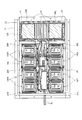
- FIG. 1 is a side view of a vehicle showing a state in which a battery pack according to an embodiment of the present invention is disposed below a floor panel.
- FIG. 2 is a plan view of FIG. 1 showing a state where a floor panel is removed.
- FIG. 3 is an enlarged view of the battery pack shown in FIG. 2.
- 1 is a schematic perspective view of a battery pack according to an embodiment of the present invention. It is a schematic perspective view which shows the 2nd battery module by embodiment of this invention.
- 1 is a vehicle body
- 2 is a passenger compartment
- 3 is a motor room equipped with an electric motor for traveling
- 4 is front left and right wheels
- 5 is left and right rear wheels
- 6 is a front seat
- 7 is a rear seat.
- 11 is a battery pack.
- the battery pack 11 includes first battery modules 13FL and 13FR disposed on the front side in the vehicle front-rear direction, second battery modules 13CL and 13CR disposed on the center side in the vehicle front-rear direction, and first battery modules 13CL and 13CR disposed on the rear side in the vehicle front-rear direction.
- the unit is composed of three battery modules 13R. These battery modules 13FL, 13FR, 13CL, 13CR, and 13R are arranged on the lower side of the floor panel in a state of being housed in the battery pack case 14 shown in FIG.
- the battery pack 11 includes a first battery module 13FL, 13FR disposed below the left and right front seats 6 and a third battery disposed below the left and right rear seats 7, as shown in FIGS.
- the module 13R includes the second battery modules 13CL and 13CR disposed immediately below the floor panel between the left and right front seats 6 and the left and right rear seats 7.
- the first battery module 13FL on the left side of the front is a battery module in which two battery modules in which four battery shells 12 are stacked in the vertical direction are arranged in parallel in the front-rear direction.
- the first battery module 13FR on the front right side is a battery module in which two battery modules in which four battery shells 12 are stacked in the vertical direction with the battery shell 12 placed horizontally are arranged in front and rear.
- a large number of battery shells 12 are stacked in the longitudinal direction so as to be substantially the same as the entire length of the rear seat 7 along the vehicle width direction. Is.
- the second battery module 13CL on the left side of the center is a battery module in which two battery modules, in which two battery shells 12 are stacked in the vertical direction with the battery shell 12 placed horizontally as shown in FIGS.
- the second battery module 13CR on the right side of the center is a battery module in which two battery modules in which two battery shells 12 are stacked in the vertical direction with the battery shell 12 placed horizontally are arranged in front and rear.
- each of the first battery modules 13FL and 13FR includes an electrode terminal 12a of the battery shell 12 constituting the first battery module 13FL on the left side and a battery shell 12 constituting the first battery module 13FR on the right side.
- the electrode terminals 12a are arranged in a direction facing each other (that is, both are directed toward the center in the vehicle width direction).
- the rear third battery module 13R is arranged so that all electrode terminals 12a of the battery shell 12 face the front of the vehicle.
- the left and right second battery modules 13CL and 13CR respectively constitute the electrode terminal 12a of the battery shell 12 constituting the left second battery module 13CL and the right second battery module 13CR.
- the battery shell 12 is arranged in such a direction that the electrode terminals 12a of the battery shell 12 face each other (that is, both are directed toward the center in the vehicle width direction).
- the electrode terminals 12a of the battery shell 12 constituting each of the battery modules 13FL, 13FR, 13CL, 13CR, 13R are respectively connected to an electric motor (in the motor room 3) via a power cable as shown in FIGS. Connect to the motor feed line 15 from the inverter.
- the power cable is routed in the center space in the vehicle width direction between the first battery modules 13FL and 13FR on the front left and right, and in the center space in the vehicle width direction between the second battery modules 13CL and 13CR on the center left and right.
- FIG. 4 is a schematic perspective view of the battery shell.
- the height of the first battery modules 13FL, 13FR (hereinafter also referred to as the first battery module 13F) when mounted on the vehicle is h1
- the second battery modules 13CL, 13CR hereinafter also referred to as the second battery module 13C.
- the height when mounted on a vehicle is h2
- the height when the third battery module 13R is mounted on a vehicle is h3, h3> h1> h2.
- the first battery module 13F is located below the left and right front seats 6, and the third battery module 13R is located below the left and right rear seats 7. Therefore, by making the heights h1 and h3 described above larger than the height h2, the space below the seat in the passenger compartment 2 can be effectively used as a space for mounting the battery shell 12, and the comfort of the passenger compartment 2 is impaired. Many batteries can be installed. Further, since the height h3 is higher than the height h1, the seat surface of the rear seat 32R is higher than the seat surface of the front seat 32F in the passenger compartment 2. With this setting, it is possible to ensure good visibility of the passengers in the left and right rear seats 7.
- the total number of the battery shells 12 of the first battery module 13F and the second battery module 13C and the total number of the battery shells 12 of the third battery module 13R are the same.
- the area occupied by the third battery module 13R is smaller than the area occupied by the first battery module 13F and the second battery module 13C.
- the center of gravity of the battery pack 11 is located relatively rearward in the vehicle longitudinal direction. Since a traveling electric motor or the like is disposed in front of the vehicle, the center of gravity of the battery pack 11 is disposed relatively rearward so that the weight distribution of the entire vehicle is brought closer to the center position in the front-rear direction. be able to. Thereby, stability of vehicle behavior can be secured.
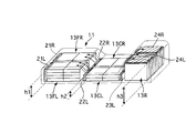
- FIG. 5 is a schematic diagram showing the second battery module.
- the battery shell 12 is formed in a substantially rectangular parallelepiped shape, has a long side p1, a short side p2, and a height side p3, and the lengths of the battery shells 12 are configured to have a size relationship of p1> p2> p3.
- the battery shell 12 is surrounded by a plane 121 surrounded by a long side p1 and a short side p2, a long side 122 surrounded by a long side p1 and a height side p3, and a short side p2 and a height side p3.
- a short side 123 is provided on the short side surface 123.
- the first battery module 13F and the second battery module 13C are arranged such that the short side p2 of the battery shell 12 is along the vehicle front-rear direction.
- the first battery module 13F and the second battery module 13C are modules that are disposed in a region where the restriction in the height direction is relatively larger than the restriction in the width direction. Therefore, even if the long side p1 is arranged along the vehicle width direction, a space between the left and right battery modules can be secured, and wiring and the like can be facilitated.
- the integration density of the battery shells 12 can be increased by arranging the short side p2 along the vehicle longitudinal direction.
- the height of the battery module can be finely adjusted by arranging the height side p3 that is the shortest length along the vehicle vertical direction.
- the height can be adjusted by the stacking state of the battery shells 12. Therefore, the battery shell 12 can be mounted efficiently by making the adjustment unit fine.
- the third battery module 13R is arranged with the height side p3 of the battery shell 12 along the vehicle width direction. Thereby, since the number of stacked battery shells 12 can be finely adjusted, a large number of battery shells 12 can be arranged by effectively using the space below the left and right rear seats 7.
- a thin heater module (heater module) for heating each battery module to prevent freezing when not in use will be described with reference to FIGS. 2 and 3, for the sake of clarity, the thin heater module is shown with hatching.
- This thin heater module is a so-called PTC heater, and its resistance value changes so as to maintain the temperature after being raised to a predetermined temperature by energization.
- the PTC heater and a soaking plate that uniformly distributes heat are configured to be able to uniformly heat the area range set.
- a method of arranging the nichrome wire meandering or a method of circulating hot water along a predetermined flow path can be applied to the heater itself, and the heater is not particularly limited.
- the thin heater modules 23L and 23R are provided close to the long side surface 122 of the battery shell 12 as shown by the hatched area in FIG. That is, in order to efficiently heat the entire battery module, it is necessary to transmit heat uniformly to the stacked battery shells 12. If the thin heater module is provided on the flat surface 121, only the battery shell 12 stacked at the upper end or the lower end adjacent to the thin heater module is heated, and the battery shell 12 stacked at the center in the vertical direction is heated. It is difficult to stabilize the performance due to insufficient heating.
- the thin heater module is provided on the short side surface 123, although all the battery shells 12 can be heated, there is a problem that the heating efficiency is low because the area facing the thin heater module is small.
- the thin heater modules 23L and 23R so as to face the long side surface 122, all the battery shells 12 are uniformly heated and the heating efficiency is improved.
- the front left and right first battery modules 13FL and 13FR have a large heat capacity in which the battery shells 12 are stacked in four stages as described above.
- the second battery modules 13CL and 13CR at the center left and right are obtained by stacking the battery shells 12 in two stages, have a small heat capacity, and are liable to lower the temperature.
- the thin battery modules 21L and 21R are provided only on the front side of the first battery modules 13FL and 13FR on the front left and right.
- the thin heater modules 22L and 22R are provided in the front, and the thin heater modules 23L and 23R are also provided in the rear.
- the reason why the thin heater modules 21L and 21R are disposed only in front of the first battery module 13 is that the front is easily affected by traveling wind and the like and is relatively easily cooled. Further, the cost can be reduced by narrowing the installation area of the thin heater module.
- the air heated by the thin heater module 22 that heats the second battery module 13C moves upward.
- the first battery module 13F can also be heated by this warm air.
- the air heated by the thin heater module 23 that heats the second battery module 13C moves upward.
- the third battery module 13R can also be heated by this warm air. That is, since the second battery module 13C is at a lower position than the other battery modules, the other battery modules are also heated using this positional relationship.
- the rear third battery module 13R has a different stacking direction from the first battery module 13F and the second battery module 13C.
- the thin battery heater 24 is also disposed on the upper surface side of the vehicle.
- the third battery module 13R has a larger number of stacked battery shells 12 than the front left and right first battery modules 13FL and 13FR, and has the largest heat capacity.
- the side surface side in the vehicle width direction is relatively susceptible to traveling wind and the like, and the vicinity of the center in the vehicle width direction of the third battery module 13R is most difficult to cool. Therefore, the rear third battery module 13R is provided with thin heater modules 24L and 24R only in the upper end regions of the battery shell 12 in the stacking direction.
- the thin heater modules 24L and 24R are installed in the areas at both ends, and not in the center area. Thereby, even if the installation area
- the thin heater modules 21L and 21R are respectively placed in close proximity to the front left battery module 13FL and the front right battery module 13FR and attached to the battery module mounting surface 14a of the battery pack case 14.
- the thin heater modules 22L and 22R are arranged close to the front side of the center left battery module 13CL and the center right battery module 13CR, respectively, and attached to the battery module mounting surface 14a of the battery pack case 14.
- the thin heater modules 23L and 23R are arranged close to the rear side of the center left battery module 13CL and the center right battery module 13CR, respectively, and attached to the battery module mounting surface 14a of the battery pack case 14.
- the thin heater modules 24L and 24R are located close to the upper side of both ends in the battery shell stacking direction of the rear battery module 13R, and are attached to the battery module mounting surface 14a of the battery pack case 14.
- the battery power cable is routed in the center space in the vehicle width direction between the front left and right battery modules 13FL and 13FR and in the center space in the vehicle width direction between the center left and right battery modules 13CL and 13CR.
- the electrode terminals of the thin heater modules 21L, 21R, 22L, 22R, 23L, 23R, 24L, 24R are the center space in the vehicle width direction between the front left and right battery modules 13FL, 13FR, and the center left and right battery modules 13CL, respectively. Therefore, it should be installed on the side close to the center space in the vehicle width direction between 13CRs.
- the electrode terminals of the thin heater modules 21L and 21R that are arranged close to each other in front of the front left battery module 13FL and the front right battery module 13FR are arranged at the ends of the thin heater modules 21L and 21R that are close to each other.
- the electrode terminals of the thin heater modules 23L and 23R that are arranged close to each other on the rear side of the central left battery module 13CL and the central right battery module 13CR are also arranged at the ends close to each other of the thin heater modules 23L and 23R. .
- the thin heater modules 21L and 21R and the thin heater modules 23L and 23R can be configured in a flat plate shape as shown in FIGS.
- the electrode terminals of the thin heater modules 21L and 21R can be arranged as described above because there is no adjacent battery module in front of the front left battery module 13FL and the front right battery module 13FR, and the thin heater This is because a space for installing the electrode terminals can be secured around the ends of the modules 21L and 21R close to each other.
- the electrode terminals of the thin heater modules 23L and 23R can be arranged as described above because there is no adjacent battery module behind the central left battery module 13CL and the central right battery module 13CR, and the thin heater module 23L , 23R around the ends close to each other, it is possible to secure a space for installing the electrode terminals.
- a battery module 13 in which a plurality of rectangular battery shells 12 having three sides are stacked, and a thin module that is disposed so as to face the side surface including the side along the stacking direction of the battery module 13 and heats the battery module 13 Heater modules 21, 22, 23, and 24.
- the thin heater modules 21, 22, 23, and 24 are provided so as to face the side surfaces including the sides along the stacking direction. As a result, all the battery shells 12 are uniformly heated and heated inside the battery pack case 14, so that the heating efficiency can be improved.
- the battery shell 12 has a rectangular parallelepiped shape having a long side p1, a short side p2, and a height side p3 shorter than both sides, and the stacking direction is a direction along the height side p3. 21, 22, 23, and 24 are arranged to face the long side surface 122 that is the side surface including the long side p ⁇ b> 1.
- the length adjustment in the direction along the height side p3 of the battery module 13 can be set finely and efficiently mounted on the vehicle. it can. Further, by disposing it so as to face the long side surface 122, it is possible to uniformly heat all the battery shells 12 and to improve the heating efficiency.
- the battery module 13 includes a first battery module 13F having a first height h1 positioned below the front seat and in front of the vehicle floor panel, in order from the front of the vehicle, and a front seat and a rear seat.
- the thin heater module 21 is disposed in front of the first battery module 13F in the vehicle front-rear direction.
- the first battery module 13F disposed in front of the vehicle is easily affected by traveling wind and is easily cooled.
- cost can be reduced, ensuring heating performance.
- the first battery module 13F has a larger volume than the second battery module 13C, the heat capacity is also large. Therefore, since the rear side of the vehicle is relatively difficult to cool, even if the thin heater module 21 is installed only in front of the vehicle, sufficient heating performance can be obtained.
- the first battery module 13F is installed below the front seat, it is difficult to ensure the height direction. Therefore, the battery shell 12 can be efficiently arranged by stacking the battery shell 12 along the vehicle vertical direction and arranging the long side surface 122 along the vehicle width direction.
- the thin heater modules 22 and 23 are arranged in front and rear of the second battery module 13C in the vehicle front-rear direction.
- the second battery module 13C is in the center portion of the battery pack 11, it has a smaller heat capacity than other battery modules and thus has a small heat capacity and is easily cooled. Therefore, the heating performance can be ensured by disposing the thin heater modules 21 both in the front and rear in the vehicle front-rear direction.
- the second battery module 13F is installed below the floor panel at the foot of the rear seat disposed between the front seat and the rear seat, it is difficult to ensure the height direction. Therefore, the battery shell 12 can be efficiently arranged by stacking the battery shell 12 along the vehicle vertical direction and arranging the long side surface 122 along the vehicle width direction.
- the thin heater module 24 is disposed above the third battery module 13R in the vehicle vertical direction.
- the restriction in the height direction is relatively gentle. Therefore, by stacking the battery shell 12 in the vehicle width direction and installing the thin heater module 24 above the battery shell 12, a sufficient space in the vehicle width direction can be secured and the battery shell 12 can be efficiently arranged.
- the thin heater module 24 is disposed in both end regions of the third battery module 13R in the vehicle width direction.
- the heat capacity is also large.
- the vehicle width direction center is not easily affected by outside air and is not easily cooled. Therefore, by installing the thin heater module 24 in both end regions in the vehicle width direction, in other words, not in the center region in the vehicle width direction, sufficient heating performance can be obtained while reducing costs.
- all the battery shells are uniformly heated and the battery shells are directly heated, so that it is possible to improve the heating efficiency.
Landscapes
- Engineering & Computer Science (AREA)
- Chemical & Material Sciences (AREA)
- Chemical Kinetics & Catalysis (AREA)
- Electrochemistry (AREA)
- General Chemical & Material Sciences (AREA)
- Power Engineering (AREA)
- Mechanical Engineering (AREA)
- Transportation (AREA)
- Sustainable Energy (AREA)
- Sustainable Development (AREA)
- Life Sciences & Earth Sciences (AREA)
- Manufacturing & Machinery (AREA)
- Aviation & Aerospace Engineering (AREA)
- Physics & Mathematics (AREA)
- Electromagnetism (AREA)
- Battery Mounting, Suspending (AREA)
- Secondary Cells (AREA)
- Arrangement Or Mounting Of Propulsion Units For Vehicles (AREA)
- Electric Propulsion And Braking For Vehicles (AREA)
Abstract
Priority Applications (6)
| Application Number | Priority Date | Filing Date | Title |
|---|---|---|---|
| KR1020137026229A KR20130133279A (ko) | 2011-03-11 | 2012-02-29 | 배터리 팩 |
| US14/004,067 US20130344371A1 (en) | 2011-03-11 | 2012-02-29 | Battery pack |
| CA2829867A CA2829867A1 (fr) | 2011-03-11 | 2012-02-29 | Module de batterie |
| RU2013145549/07A RU2539351C1 (ru) | 2011-03-11 | 2012-02-29 | Аккумуляторный блок |
| CN2012800129223A CN103430377A (zh) | 2011-03-11 | 2012-02-29 | 蓄电池组 |
| EP12757333.5A EP2685545A4 (fr) | 2011-03-11 | 2012-02-29 | Module de batterie |
Applications Claiming Priority (2)
| Application Number | Priority Date | Filing Date | Title |
|---|---|---|---|
| JP2011054086A JP2012190691A (ja) | 2011-03-11 | 2011-03-11 | バッテリモジュール |
| JP2011-054086 | 2011-03-11 |
Publications (1)
| Publication Number | Publication Date |
|---|---|
| WO2012124481A1 true WO2012124481A1 (fr) | 2012-09-20 |
Family
ID=46830556
Family Applications (1)
| Application Number | Title | Priority Date | Filing Date |
|---|---|---|---|
| PCT/JP2012/055124 WO2012124481A1 (fr) | 2011-03-11 | 2012-02-29 | Module de batterie |
Country Status (8)
| Country | Link |
|---|---|
| US (1) | US20130344371A1 (fr) |
| EP (1) | EP2685545A4 (fr) |
| JP (1) | JP2012190691A (fr) |
| KR (1) | KR20130133279A (fr) |
| CN (1) | CN103430377A (fr) |
| CA (1) | CA2829867A1 (fr) |
| RU (1) | RU2539351C1 (fr) |
| WO (1) | WO2012124481A1 (fr) |
Families Citing this family (8)
| Publication number | Priority date | Publication date | Assignee | Title |
|---|---|---|---|---|
| JP5825694B2 (ja) * | 2011-12-09 | 2015-12-02 | 本田技研工業株式会社 | バッテリパックの車載構造 |
| US20160056418A1 (en) * | 2014-08-21 | 2016-02-25 | Ford Global Technologies, Llc | Li-ion monoblock battery for stop/start applications |
| US20160093848A1 (en) | 2014-09-30 | 2016-03-31 | Johnson Controls Technology Company | Modular approach for advanced battery modules having different electrical characteristics |
| RU2625461C2 (ru) * | 2015-01-27 | 2017-07-14 | Сергей Борисович Орлов | Источник тока |
| WO2018221002A1 (fr) * | 2017-05-30 | 2018-12-06 | 日産自動車株式会社 | Bloc-batterie à monter sur un véhicule |
| JP7085555B2 (ja) * | 2017-08-22 | 2022-06-16 | ビークルエナジージャパン株式会社 | 電池パック |
| JP7339065B2 (ja) * | 2019-08-21 | 2023-09-05 | マツダ株式会社 | 車両用バッテリパック |
| DE102020209492A1 (de) * | 2020-07-28 | 2022-02-03 | Robert Bosch Gesellschaft mit beschränkter Haftung | Beheiztes Batteriemodul |
Citations (7)
| Publication number | Priority date | Publication date | Assignee | Title |
|---|---|---|---|---|
| JPH06283215A (ja) * | 1993-03-26 | 1994-10-07 | Ngk Insulators Ltd | 高温二次電池の加熱装置及び加熱方法 |
| JPH09161853A (ja) * | 1995-12-08 | 1997-06-20 | Nissan Motor Co Ltd | 二次電池の温度制御装置 |
| JP2008047371A (ja) * | 2006-08-11 | 2008-02-28 | Toshiba Corp | 組電池および組電池の充放電方法 |
| JP2008186621A (ja) | 2007-01-26 | 2008-08-14 | Panasonic Ev Energy Co Ltd | 積層薄型ヒータ、リード線付き積層薄型ヒータ、ヒータ付き電池構造体、及びヒータユニット |
| JP2010238519A (ja) * | 2009-03-31 | 2010-10-21 | Honda Motor Co Ltd | 組電池装置 |
| JP2011014436A (ja) * | 2009-07-03 | 2011-01-20 | Panasonic Corp | バッテリー加熱装置 |
| JP2011023292A (ja) * | 2009-07-17 | 2011-02-03 | Nissan Motor Co Ltd | バッテリーパック |
Family Cites Families (11)
| Publication number | Priority date | Publication date | Assignee | Title |
|---|---|---|---|---|
| US6085854A (en) * | 1994-12-13 | 2000-07-11 | Nissan Motor Co., Ltd. | Battery frame structure for electric motorcar |
| RU2088001C1 (ru) * | 1995-05-15 | 1997-08-20 | Военный автомобильный институт | Аккумуляторная батарея с внутренним обогревом |
| JP3767004B2 (ja) * | 1996-03-11 | 2006-04-19 | マツダ株式会社 | エンジンの二次エア供給装置 |
| US5948298A (en) * | 1996-04-26 | 1999-09-07 | Ford Global Technologies, Inc. | Battery heating system |
| JPH11213962A (ja) * | 1998-01-30 | 1999-08-06 | Yuasa Corp | 蓄電池 |
| DE10260551A1 (de) * | 2002-12-21 | 2004-07-01 | Otto Hans Happe | Batterie für die Verwendung in Kraftfahrzeugen |
| US7556885B2 (en) * | 2003-11-14 | 2009-07-07 | Sony Corporation | Battery pack |
| US7531270B2 (en) * | 2006-10-13 | 2009-05-12 | Enerdel, Inc. | Battery pack with integral cooling and bussing devices |
| JP5326503B2 (ja) * | 2008-11-05 | 2013-10-30 | 株式会社デンソー | 電池冷却装置 |
| JP5640382B2 (ja) * | 2009-05-26 | 2014-12-17 | 日産自動車株式会社 | 車両のバッテリアセンブリ冷却構造、および、ウォータージャケット付きバッテリアセンブリ |
| JP5861484B2 (ja) * | 2011-03-11 | 2016-02-16 | 日産自動車株式会社 | 車載用バッテリ |
-
2011
- 2011-03-11 JP JP2011054086A patent/JP2012190691A/ja active Pending
-
2012
- 2012-02-29 EP EP12757333.5A patent/EP2685545A4/fr not_active Withdrawn
- 2012-02-29 US US14/004,067 patent/US20130344371A1/en not_active Abandoned
- 2012-02-29 WO PCT/JP2012/055124 patent/WO2012124481A1/fr active Application Filing
- 2012-02-29 KR KR1020137026229A patent/KR20130133279A/ko not_active Application Discontinuation
- 2012-02-29 CA CA2829867A patent/CA2829867A1/fr not_active Abandoned
- 2012-02-29 CN CN2012800129223A patent/CN103430377A/zh active Pending
- 2012-02-29 RU RU2013145549/07A patent/RU2539351C1/ru not_active IP Right Cessation
Patent Citations (7)
| Publication number | Priority date | Publication date | Assignee | Title |
|---|---|---|---|---|
| JPH06283215A (ja) * | 1993-03-26 | 1994-10-07 | Ngk Insulators Ltd | 高温二次電池の加熱装置及び加熱方法 |
| JPH09161853A (ja) * | 1995-12-08 | 1997-06-20 | Nissan Motor Co Ltd | 二次電池の温度制御装置 |
| JP2008047371A (ja) * | 2006-08-11 | 2008-02-28 | Toshiba Corp | 組電池および組電池の充放電方法 |
| JP2008186621A (ja) | 2007-01-26 | 2008-08-14 | Panasonic Ev Energy Co Ltd | 積層薄型ヒータ、リード線付き積層薄型ヒータ、ヒータ付き電池構造体、及びヒータユニット |
| JP2010238519A (ja) * | 2009-03-31 | 2010-10-21 | Honda Motor Co Ltd | 組電池装置 |
| JP2011014436A (ja) * | 2009-07-03 | 2011-01-20 | Panasonic Corp | バッテリー加熱装置 |
| JP2011023292A (ja) * | 2009-07-17 | 2011-02-03 | Nissan Motor Co Ltd | バッテリーパック |
Non-Patent Citations (1)
| Title |
|---|
| See also references of EP2685545A4 |
Also Published As
| Publication number | Publication date |
|---|---|
| US20130344371A1 (en) | 2013-12-26 |
| JP2012190691A (ja) | 2012-10-04 |
| EP2685545A1 (fr) | 2014-01-15 |
| CA2829867A1 (fr) | 2012-09-20 |
| KR20130133279A (ko) | 2013-12-06 |
| RU2539351C1 (ru) | 2015-01-20 |
| CN103430377A (zh) | 2013-12-04 |
| EP2685545A4 (fr) | 2014-08-27 |
Similar Documents
| Publication | Publication Date | Title |
|---|---|---|
| WO2012124555A1 (fr) | Batterie pour installation dans un véhicule | |
| WO2012124568A1 (fr) | Batterie pour installation dans un véhicule | |
| WO2012124481A1 (fr) | Module de batterie | |
| JP5914609B2 (ja) | 車載用バッテリー | |
| EP2730484B1 (fr) | Véhicule à propulsion électrique | |
| EP2685782B1 (fr) | Modules de chauffage | |
| JP6099194B2 (ja) | 蓄電装置の冷却構造 | |
| JP2007329047A (ja) | 電池パック | |
| JP6614650B2 (ja) | 車載用バッテリー | |
| WO2012124471A1 (fr) | Module chauffant | |
| JP2023042875A (ja) | 電池支持構造体 |
Legal Events
| Date | Code | Title | Description |
|---|---|---|---|
| 121 | Ep: the epo has been informed by wipo that ep was designated in this application |
Ref document number: 12757333 Country of ref document: EP Kind code of ref document: A1 |
|
| WWE | Wipo information: entry into national phase |
Ref document number: 14004067 Country of ref document: US |
|
| ENP | Entry into the national phase |
Ref document number: 2829867 Country of ref document: CA |
|
| NENP | Non-entry into the national phase |
Ref country code: DE |
|
| REEP | Request for entry into the european phase |
Ref document number: 2012757333 Country of ref document: EP |
|
| WWE | Wipo information: entry into national phase |
Ref document number: 2012757333 Country of ref document: EP |
|
| ENP | Entry into the national phase |
Ref document number: 20137026229 Country of ref document: KR Kind code of ref document: A |
|
| ENP | Entry into the national phase |
Ref document number: 2013145549 Country of ref document: RU Kind code of ref document: A |