WO2012121386A1 - 排気ガス浄化装置 - Google Patents
排気ガス浄化装置 Download PDFInfo
- Publication number
- WO2012121386A1 WO2012121386A1 PCT/JP2012/056169 JP2012056169W WO2012121386A1 WO 2012121386 A1 WO2012121386 A1 WO 2012121386A1 JP 2012056169 W JP2012056169 W JP 2012056169W WO 2012121386 A1 WO2012121386 A1 WO 2012121386A1
- Authority
- WO
- WIPO (PCT)
- Prior art keywords
- catalyst structure
- catalyst
- exhaust gas
- sheet
- cushion material
- Prior art date
- Legal status (The legal status is an assumption and is not a legal conclusion. Google has not performed a legal analysis and makes no representation as to the accuracy of the status listed.)
- Ceased
Links
Images




Classifications
-
- F—MECHANICAL ENGINEERING; LIGHTING; HEATING; WEAPONS; BLASTING
- F01—MACHINES OR ENGINES IN GENERAL; ENGINE PLANTS IN GENERAL; STEAM ENGINES
- F01N—GAS-FLOW SILENCERS OR EXHAUST APPARATUS FOR MACHINES OR ENGINES IN GENERAL; GAS-FLOW SILENCERS OR EXHAUST APPARATUS FOR INTERNAL-COMBUSTION ENGINES
- F01N3/00—Exhaust or silencing apparatus having means for purifying, rendering innocuous, or otherwise treating exhaust
- F01N3/08—Exhaust or silencing apparatus having means for purifying, rendering innocuous, or otherwise treating exhaust for rendering innocuous
- F01N3/10—Exhaust or silencing apparatus having means for purifying, rendering innocuous, or otherwise treating exhaust for rendering innocuous by thermal or catalytic conversion of noxious components of exhaust
- F01N3/24—Exhaust or silencing apparatus having means for purifying, rendering innocuous, or otherwise treating exhaust for rendering innocuous by thermal or catalytic conversion of noxious components of exhaust characterised by constructional aspects of converting apparatus
- F01N3/28—Construction of catalytic reactors
- F01N3/2839—Arrangements for mounting catalyst support in housing, e.g. with means for compensating thermal expansion or vibration
- F01N3/2842—Arrangements for mounting catalyst support in housing, e.g. with means for compensating thermal expansion or vibration specially adapted for monolithic supports, e.g. of honeycomb type
-
- C—CHEMISTRY; METALLURGY
- C04—CEMENTS; CONCRETE; ARTIFICIAL STONE; CERAMICS; REFRACTORIES
- C04B—LIME, MAGNESIA; SLAG; CEMENTS; COMPOSITIONS THEREOF, e.g. MORTARS, CONCRETE OR LIKE BUILDING MATERIALS; ARTIFICIAL STONE; CERAMICS; REFRACTORIES; TREATMENT OF NATURAL STONE
- C04B38/00—Porous mortars, concrete, artificial stone or ceramic ware; Preparation thereof
- C04B38/008—Bodies obtained by assembling separate elements having such a configuration that the final product is porous or by spirally winding one or more corrugated sheets
- C04B38/0083—Bodies obtained by assembling separate elements having such a configuration that the final product is porous or by spirally winding one or more corrugated sheets from one or more corrugated sheets or sheets bearing protrusions by winding or stacking
-
- B—PERFORMING OPERATIONS; TRANSPORTING
- B01—PHYSICAL OR CHEMICAL PROCESSES OR APPARATUS IN GENERAL
- B01J—CHEMICAL OR PHYSICAL PROCESSES, e.g. CATALYSIS OR COLLOID CHEMISTRY; THEIR RELEVANT APPARATUS
- B01J37/00—Processes, in general, for preparing catalysts; Processes, in general, for activation of catalysts
- B01J37/02—Impregnation, coating or precipitation
- B01J37/0215—Coating
- B01J37/0225—Coating of metal substrates
-
- C—CHEMISTRY; METALLURGY
- C04—CEMENTS; CONCRETE; ARTIFICIAL STONE; CERAMICS; REFRACTORIES
- C04B—LIME, MAGNESIA; SLAG; CEMENTS; COMPOSITIONS THEREOF, e.g. MORTARS, CONCRETE OR LIKE BUILDING MATERIALS; ARTIFICIAL STONE; CERAMICS; REFRACTORIES; TREATMENT OF NATURAL STONE
- C04B2111/00—Mortars, concrete or artificial stone or mixtures to prepare them, characterised by specific function, property or use
- C04B2111/00241—Physical properties of the materials not provided for elsewhere in C04B2111/00
- C04B2111/0037—Materials containing oriented fillers or elements
- C04B2111/00379—Materials containing oriented fillers or elements the oriented elements being fibres
-
- C—CHEMISTRY; METALLURGY
- C04—CEMENTS; CONCRETE; ARTIFICIAL STONE; CERAMICS; REFRACTORIES
- C04B—LIME, MAGNESIA; SLAG; CEMENTS; COMPOSITIONS THEREOF, e.g. MORTARS, CONCRETE OR LIKE BUILDING MATERIALS; ARTIFICIAL STONE; CERAMICS; REFRACTORIES; TREATMENT OF NATURAL STONE
- C04B2111/00—Mortars, concrete or artificial stone or mixtures to prepare them, characterised by specific function, property or use
- C04B2111/00474—Uses not provided for elsewhere in C04B2111/00
- C04B2111/0081—Uses not provided for elsewhere in C04B2111/00 as catalysts or catalyst carriers
-
- F—MECHANICAL ENGINEERING; LIGHTING; HEATING; WEAPONS; BLASTING
- F01—MACHINES OR ENGINES IN GENERAL; ENGINE PLANTS IN GENERAL; STEAM ENGINES
- F01N—GAS-FLOW SILENCERS OR EXHAUST APPARATUS FOR MACHINES OR ENGINES IN GENERAL; GAS-FLOW SILENCERS OR EXHAUST APPARATUS FOR INTERNAL-COMBUSTION ENGINES
- F01N3/00—Exhaust or silencing apparatus having means for purifying, rendering innocuous, or otherwise treating exhaust
- F01N3/08—Exhaust or silencing apparatus having means for purifying, rendering innocuous, or otherwise treating exhaust for rendering innocuous
- F01N3/10—Exhaust or silencing apparatus having means for purifying, rendering innocuous, or otherwise treating exhaust for rendering innocuous by thermal or catalytic conversion of noxious components of exhaust
- F01N3/24—Exhaust or silencing apparatus having means for purifying, rendering innocuous, or otherwise treating exhaust for rendering innocuous by thermal or catalytic conversion of noxious components of exhaust characterised by constructional aspects of converting apparatus
- F01N3/28—Construction of catalytic reactors
- F01N3/2803—Construction of catalytic reactors characterised by structure, by material or by manufacturing of catalyst support
- F01N3/2835—Construction of catalytic reactors characterised by structure, by material or by manufacturing of catalyst support fibrous
-
- F—MECHANICAL ENGINEERING; LIGHTING; HEATING; WEAPONS; BLASTING
- F01—MACHINES OR ENGINES IN GENERAL; ENGINE PLANTS IN GENERAL; STEAM ENGINES
- F01N—GAS-FLOW SILENCERS OR EXHAUST APPARATUS FOR MACHINES OR ENGINES IN GENERAL; GAS-FLOW SILENCERS OR EXHAUST APPARATUS FOR INTERNAL-COMBUSTION ENGINES
- F01N3/00—Exhaust or silencing apparatus having means for purifying, rendering innocuous, or otherwise treating exhaust
- F01N3/08—Exhaust or silencing apparatus having means for purifying, rendering innocuous, or otherwise treating exhaust for rendering innocuous
- F01N3/10—Exhaust or silencing apparatus having means for purifying, rendering innocuous, or otherwise treating exhaust for rendering innocuous by thermal or catalytic conversion of noxious components of exhaust
- F01N3/24—Exhaust or silencing apparatus having means for purifying, rendering innocuous, or otherwise treating exhaust for rendering innocuous by thermal or catalytic conversion of noxious components of exhaust characterised by constructional aspects of converting apparatus
- F01N3/28—Construction of catalytic reactors
- F01N3/2839—Arrangements for mounting catalyst support in housing, e.g. with means for compensating thermal expansion or vibration
- F01N3/2853—Arrangements for mounting catalyst support in housing, e.g. with means for compensating thermal expansion or vibration using mats or gaskets between catalyst body and housing
-
- Y—GENERAL TAGGING OF NEW TECHNOLOGICAL DEVELOPMENTS; GENERAL TAGGING OF CROSS-SECTIONAL TECHNOLOGIES SPANNING OVER SEVERAL SECTIONS OF THE IPC; TECHNICAL SUBJECTS COVERED BY FORMER USPC CROSS-REFERENCE ART COLLECTIONS [XRACs] AND DIGESTS
- Y02—TECHNOLOGIES OR APPLICATIONS FOR MITIGATION OR ADAPTATION AGAINST CLIMATE CHANGE
- Y02A—TECHNOLOGIES FOR ADAPTATION TO CLIMATE CHANGE
- Y02A50/00—TECHNOLOGIES FOR ADAPTATION TO CLIMATE CHANGE in human health protection, e.g. against extreme weather
- Y02A50/20—Air quality improvement or preservation, e.g. vehicle emission control or emission reduction by using catalytic converters
-
- Y—GENERAL TAGGING OF NEW TECHNOLOGICAL DEVELOPMENTS; GENERAL TAGGING OF CROSS-SECTIONAL TECHNOLOGIES SPANNING OVER SEVERAL SECTIONS OF THE IPC; TECHNICAL SUBJECTS COVERED BY FORMER USPC CROSS-REFERENCE ART COLLECTIONS [XRACs] AND DIGESTS
- Y10—TECHNICAL SUBJECTS COVERED BY FORMER USPC
- Y10T—TECHNICAL SUBJECTS COVERED BY FORMER US CLASSIFICATION
- Y10T156/00—Adhesive bonding and miscellaneous chemical manufacture
- Y10T156/10—Methods of surface bonding and/or assembly therefor
- Y10T156/1002—Methods of surface bonding and/or assembly therefor with permanent bending or reshaping or surface deformation of self sustaining lamina
- Y10T156/1036—Bending of one piece blank and joining edges to form article
- Y10T156/1038—Hollow cylinder article
Definitions
- the present invention relates to an exhaust gas purifying apparatus in which a catalyst structure carrying a metal catalyst is accommodated in a cylindrical container via a cushion material.
- An exhaust gas purifying device for purifying exhaust gas discharged from an engine of a vehicle or the like is usually a cylindrical metal container comprising a catalyst structure (catalyst carrier) carrying a noble metal catalyst such as platinum, rhodium or palladium.
- a catalyst structure of such an exhaust gas purification device is mainly used which has a honeycomb structure made of metal or ceramic.
- the catalyst structure is made of ceramics
- the ceramic catalyst structure in the process of being used in a vehicle muffler or exhaust pipe, when intense vibration exerted from the vehicle is applied, There is a possibility that the catalyst structure is displaced in the press-fitting direction with respect to the cushion material. That is, the ceramic catalyst structure usually has a low surface roughness, so that the frictional resistance generated on the contact surface with the cushion material is small, and the ceramic catalyst structure is slid with respect to the cushion material to which severe vibration is applied. May shift.
- the present invention has been made in view of such circumstances, and suppresses displacement of the catalyst structure relative to the cushion material even when intense vibration is applied during use without increasing the pressure of the cushion material against the catalyst structure. It is an object of the present invention to provide an exhaust gas purifying device that can perform the above-described operation.
- the invention according to claim 1 is an exhaust gas purifying apparatus in which a catalyst structure carrying a metal catalyst is accommodated in a cylindrical container through a cushioning material, and the catalyst structure is applied to a wet papermaking method. It is characterized by comprising a sheet-like catalyst structure obtained in this manner, and the catalyst structure is press-fitted and fixed to the cushion material.
- the fiber orientation is substantially perpendicular to the press-fitting direction with respect to the cushion material on the contact surface of the catalyst structure with the cushion material. It is characterized by being formed.
- the invention according to claim 3 is the exhaust gas purifying apparatus according to claim 2, wherein the catalyst structure is obtained by adding a flocculant to a slurry in which a predetermined fiber and a binder are mixed in a predetermined amount of water. It is obtained by firing a sheet-like structure produced by paper making a floc, and the fiber orientation is formed when the sheet-like structure is made.
- the catalyst structure is formed into a corrugated shape on at least one surface of the sheet-shaped structure having a predetermined length. It is characterized by comprising a honeycomb structure formed by bonding a body and winding it into a roll.
- the catalyst structure is composed of a sheet-like catalyst structure obtained by a wet papermaking method, and the catalyst structure is press-fitted and fixed to the cushion material.
- the frictional resistance between the cushioning material and the cushioning material can be increased, and the displacement of the catalyst structure relative to the cushioning material can be suppressed even when intense vibration is applied during the use process without increasing the pressure of the cushioning material against the catalytic structure. can do.
- the fiber orientation is formed on the contact surface of the catalyst structure with the cushion material in a direction substantially perpendicular to the press-fitting direction with respect to the cushion material, the catalyst structure and the cushion material
- the frictional resistance in the press-fitting direction between the catalyst structure and the cushion structure can be increased without increasing the pressure of the cushion structure on the catalyst structure, even if intense vibration is applied during use. It can suppress more reliably.
- the catalyst structure is a sheet formed by paper-making floc obtained by adding a flocculant to a slurry in which predetermined fibers and a binder are mixed in a predetermined amount of water. While obtained by firing the structure, and fiber orientation is formed when the sheet-like structure is made, a catalyst structure in which the fiber orientation is formed in a direction substantially orthogonal to the press-fitting direction with respect to the cushion material can be more easily obtained. Obtainable.
- the catalyst structure has a honeycomb structure in which a sheet-like structure formed in a corrugated shape is bonded to at least one surface of the sheet-like structure having a predetermined length, and wound in a roll shape. Therefore, it is possible to more easily obtain a honeycomb structured catalyst structure in which fiber orientation is formed in a direction substantially perpendicular to the press-fitting direction with respect to the cushion material.
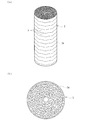
- the exhaust gas purifying apparatus is for purifying exhaust gas that is attached to, for example, a vehicle muffler or exhaust pipe and exhausted from an engine. As shown in FIG. And a cylindrical cushion material 2 and a columnar catalyst structure 3 (catalyst carrier).
- the container 1 is a metal cylindrical member made of stainless steel, and its outer peripheral surface is fixed in contact with the inner wall of the muffler or exhaust pipe of the vehicle, and the outer peripheral surface 2a (
- the cushion material 2 can be accommodated by abutting (see FIG. 3).
- the container 1 accommodates the cushion material 2 and the catalyst structure 3 in the inside thereof, thereby constituting a casing of the exhaust gas purifying apparatus.
- the cushion material 2 is made of, for example, a nonwoven fabric of about 70% alumina fiber and about 30% silica fiber, and is formed by forming the nonwoven fabric into a cylindrical shape as shown in FIG.
- the cushion material 2 is assembled with its outer peripheral surface 2a in contact with the inner peripheral surface of the container 1, and its inner peripheral surface 2b is in contact with the outer peripheral surface 3a (see FIG. 2) of the catalyst structure 3. As a result, it is configured to be interposed between the container 1 and the catalyst structure 3.
- the catalyst structure 3 according to the present embodiment is composed of a sheet-like (paper-like) catalyst structure obtained by a wet papermaking method (so-called “papermaking method”), as shown in FIG.
- the catalyst structure 3 is formed into a cylindrical shape (formed into a honeycomb structure), and then pressed into the cushion material 2 and fixed.
- the contact surface (that is, the outer peripheral surface 3a) of the catalyst structure 3 according to this embodiment with the cushion material 2 is substantially perpendicular to the press-fitting direction (vertical direction in FIG. 2) with respect to the cushion material 2.
- the fiber orientation is formed in the (direction).
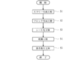
- an aqueous solution is prepared by introducing ceramic powder, predetermined fibers (heat-resistant fibers) containing alumina / silica fibers, catalyst powder and inorganic binder (binder), pore adjuster, etc. into a predetermined amount of water. Then, a slurry in which these contents are uniformly dispersed is prepared (slurry generating step S1).
- flocculant is added to the slurry to generate a floc (floc generating step S2), and then the floc is made (wet paper making method) to generate a sheet-like (paper-like) porous structure (sheet formation) Step S3).
- the heat-resistant fiber is made of amorphous ceramics mainly composed of silica and alumina, and is formed into a sheet shape by a wet papermaking method to form the catalyst structure 3.
- the heat-resistant fiber may be composed of other materials, such as aramid fiber, as long as the fiber is chemically and physically stable and the fibers are strongly entangled to obtain a high-strength structure.
- Organic fibers can also be used.
- a structure may be obtained by forming glass fiber or carbon fiber having high heat resistance and chemically stable into a paper shape by a wet papermaking method.
- the metal catalyst powder is a catalyst powder having a metal oxide as a carrier, and is then uniformly dispersed and adhered in the pores (voids) of the porous structure by a wet papermaking method.
- Rare noble metals such as rhodium and palladium can be used. If such a noble metal is used, for example, NO x contained in the exhaust gas is reduced and becomes N 2 to be purified (detoxified).
- an inorganic binder is a binder between a heat-resistant fiber and a metal catalyst, and those bonded by heat fusion such as glass and colloidal inorganic oxides (particularly colloidal silica, colloidal alumina, colloidal zirconia are dispersed). It is preferable to use one of them because it has excellent properties and high strength can be obtained.) It is roughly divided into two types, such as those that bring about their strength by chemical bonding and sintering by dehydration reaction such as silica gel.
- the inorganic binder used in the present embodiment is preferably the latter, that is, a material that is chemically bonded by a dehydration reaction.
- the flocculant for generating flocs contains a polymer flocculant and a metal cation, has a strong charge, and in the aqueous solution, the charge of a substance that is electrically charged and repels each other. It is neutralized and strongly entangled.
- the polymer flocculant has a function of entering between the entangled fibers and further strengthening the binding force, and the metal cation containing an Al 3+ cation in an aqueous solution of alum, aluminum sulfate or the like is used.
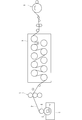
- the above-described flock (floc generated through the slurry generation step S ⁇ b> 1 and the flock generation step S ⁇ b> 2) including predetermined fibers, a binder, and the like is placed in the storage container 4. It is stored in a fixed amount and scooped up by a circular net 5 (a net-like member that adheres a certain amount of slurry to the outer peripheral surface and conveys it to the roller 6) that is rotationally driven in a range including the upper and lower sides of the liquid level in the container 4. A sheet-like structure P having a predetermined thickness is obtained. The sheet-like structure P is continuously conveyed from the roller 6 to the roll press 7 and is adjusted to a desired thickness by applying a predetermined pressure by the roll press 7.
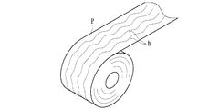
- the sheet-like structure P by which the pressure was given with the roll press 7 and was made into predetermined thickness is continuously sent to the dryer 8, and is dried in the process conveyed in the said dryer 8 ( Drying step S4). Thereafter, the dried sheet-like structure P is sequentially wound by the winding device 9 as shown in FIG. 5 (winding step S5). As a result, a predetermined amount of the sheet-like structure P can be obtained, and the sheet-like structure P is formed into a honeycomb structure as described later, and then fired to obtain a catalyst structure 3 made of a porous structure. Will be.
- the noble metal as the catalyst metal is supported in the micropores of the catalyst structure 3.
- fiber orientation is formed when the sheet-like structure P is made. That is, the sheet-like structure P is made of fibers in the conveying direction as shown in FIG. 5 during papermaking (specifically, during conveyance from papermaking by the circular mesh 5 to winding by the winding device 9). As a result, the fiber orientation h is naturally formed.
- the fiber orientation according to the present invention refers to a state in which the fibers are directed in a specific direction. In particular, in this embodiment, the orientation is formed in the transport direction (feed direction) of the sheet-like structure P.
- the sheet-like structure P taken up by the take-up device 9 has a predetermined length (long shape) that is not bent, and a corrugated (corrugated).
- the sheet-like structure Pb having a predetermined length (long shape) bent into a shape is formed into a sheet-like structure Pb having a predetermined length as shown in FIG.
- the sheet-like structure Pb formed in a corrugated shape on at least one surface of Pa is bonded with an adhesive or the like, and rolled into a roll shape as shown in FIG. This is the previous catalyst structure 3 ′ (see FIG. 4D).
- the catalyst structure 3 ′ is calcined at 1450 ° C. to 1550 ° C., for example, to obtain the catalyst structure 3 as shown in FIG.
- the catalyst structure 3 obtained through the above-described series of manufacturing steps is press-fitted and fixed to the cushion material 2 accommodated in the container 1 to obtain an exhaust gas purification apparatus as shown in FIG. Will be.
- the fiber orientation h is formed in the circumferential direction (direction substantially orthogonal to the press-fitting direction) on the outer peripheral surface 3a, and the fiber orientation h is in the inner circumference of the cushion material 2 in the press-fitted state. It is in a state facing the surface 2b.
- the surface roughness in the axial direction of the catalyst structure 3 according to the present embodiment was about 5.916 ( ⁇ m) (the graph on the right side in the figure).
- the surface roughness in the axial direction of the conventional ceramic catalyst structure was about 3.576 ( ⁇ m) (the graph on the left side in the figure).
- the surface roughness in the axial direction of the catalyst structure 3 according to this embodiment is rougher than that of a conventional ceramic catalyst structure.
- the catalyst structure 3 is composed of the sheet-like catalyst structure 3 obtained by the wet papermaking method, and the catalyst structure 3 is press-fitted into the cushion material 2 and fixed.
- the frictional resistance between the structure 3 and the cushion material 2 can be increased, and intense vibration is applied during the use process (mounted state in the vehicle) without increasing the pressure of the cushion material 2 on the catalyst structure 3.
- the displacement of the catalyst structure 3 with respect to the cushion material 2 can be suppressed.
- the fiber orientation h is formed on the contact surface of the catalyst structure 3 with the cushion material 2 in a direction substantially orthogonal to the press-fitting direction with respect to the cushion material 2, the catalyst structure 3 and the cushion material 2
- the frictional resistance in the press-fitting direction can be further increased, and the cushioning material 2 can be applied even if intense vibration is applied during the use process (mounted state in the vehicle) without increasing the pressure of the cushioning material 2 against the catalyst structure 3.
- the position shift of the catalyst structure 3 with respect to 2 can be more reliably suppressed.
- the catalyst structure 3 calcinates the sheet-like structure P produced by papermaking a floc obtained by adding a flocculant to a slurry in which a predetermined fiber and a binder are mixed in a predetermined amount of water.
- the fiber orientation is formed when the sheet-like structure P is made, the catalyst structure 3 in which the fiber orientation h is formed in a direction substantially orthogonal to the press-fitting direction with respect to the cushion material 2 is obtained more easily. be able to.
- the fiber orientation h is naturally formed in the process of transporting the sheet-like structure P at the time of papermaking, so that a separate process for forming the fiber orientation h is not required and the manufacturing cost is increased. It can be avoided.
- the catalyst structure 3 has a honeycomb structure in which a sheet-like structure Pb formed in a corrugated shape is bonded to at least one surface of a sheet-like structure Pa having a predetermined length and wound in a roll shape. Therefore, the honeycomb structured catalyst structure 3 in which the fiber orientation h is formed in a direction substantially orthogonal to the press-fitting direction with respect to the cushion material 2 can be obtained more easily. With such a honeycomb structure, the exhaust gas can be circulated favorably through the catalyst structure 3, and the purification action can be reliably performed.
- the present invention is not limited to this.
- the catalyst structure in which the fiber orientation h is not formed may be press-fitted into the cushion material 2 and fixed.
- the fiber orientation may be formed in the press-fitting direction with respect to the cushion material 2 or in a direction shifted from the press-fitting direction. That is, since the catalyst structure according to the present invention is composed of a sheet-like catalyst structure obtained by a wet papermaking method, resistance can be generated on the contact surface with the cushion material 2 by the fibers on the surface. .
- the fiber orientation h is formed when the sheet-like structure 3 is made (particularly when the sheet-like structure P is conveyed). The fiber orientation h may be formed.
- the catalyst structure is composed of a sheet-like catalyst structure obtained by a wet papermaking method, and if it is an exhaust gas purification device in which the catalyst structure is press-fitted and fixed to a cushion material, it is used for a vehicle.
- the present invention can be applied to other forms.
Landscapes
- Chemical & Material Sciences (AREA)
- Engineering & Computer Science (AREA)
- Ceramic Engineering (AREA)
- Chemical Kinetics & Catalysis (AREA)
- Materials Engineering (AREA)
- Structural Engineering (AREA)
- Organic Chemistry (AREA)
- Toxicology (AREA)
- Health & Medical Sciences (AREA)
- Combustion & Propulsion (AREA)
- Mechanical Engineering (AREA)
- General Engineering & Computer Science (AREA)
- Exhaust Gas After Treatment (AREA)
- Catalysts (AREA)
- Exhaust Gas Treatment By Means Of Catalyst (AREA)
- Manufacturing & Machinery (AREA)
Abstract
【課題】クッション材の触媒構造体に対する圧力を高めることなく、使用過程で激しい振動が付与されてもクッション材に対する触媒構造体の位置ずれを抑制することができる排気ガス浄化装置を提供する。 【解決手段】金属触媒を担持した触媒構造体3をクッション材2を介して筒状の容器1内に収容させて成る排気ガス浄化装置であって、触媒構造体3は、湿式抄紙法にて得られたシート状の触媒構造体3から成り、当該触媒構造体3をクッション材2に圧入して固定させたものであり、特に触媒構造体3におけるクッション材2との当接面には、当該クッション材2に対する圧入方向と略直交した方向に繊維配向hが形成されて成るものである。
Description
本発明は、金属触媒を担持した触媒構造体をクッション材を介して筒状の容器内に収容させて成る排気ガス浄化装置に関するものである。
車両等のエンジンから排出される排気ガスを浄化するための排気ガス浄化装置は、通常、例えば白金、ロジウムやパラジウム等の貴金属触媒を担持した触媒構造体(触媒担体)を円筒状の金属製容器(ステンレス製)内に固定されて成るとともに、車両のマフラーやエキゾーストパイプ内に取り付けられるよう構成されている。かかる排気ガス浄化装置の触媒構造体として、近時においては、金属又はセラミックから成るハニカム構造から成るものが主に用いられている。
特に、セラミック製のハニカム構造体から成る触媒構造体を用いる場合、金属製(ステンレス製)容器と比べて熱膨張率が著しく小さいことから、当該金属製(ステンレス製)容器に直接セラミック製の触媒構造体を圧入した状態では、高温時に互いの接触面において熱応力が発生してしまう。かかる熱応力が発生してしまうのを抑制すべく、従来、金属製(ステンレス製)容器とセラミックス製の触媒構造体との間にクッション材を介在させて圧入させるものが提案されている(例えば特許文献1参照)。
しかしながら、上記従来の排気ガス浄化装置においては、触媒構造体がセラミックスから成るため、車両のマフラーやエキゾーストパイプ内に取り付けられて使用される過程で、車両から及ぼされる激しい振動が付与されると、クッション材に対して触媒構造体が圧入方向にずれてしまう虞があった。すなわち、セラミック製の触媒構造体は、通常、その表面の面粗さが低いため、クッション材との接触面で生じる摩擦抵抗が小さく、激しい振動等が付与されるクッション材に対して滑って位置がずれてしまう虞がある。
然るに、上記不具合を回避するためには、触媒構造体の径方向に加えるクッション材の圧力を大きくして車両から付与される激しい振動に耐えるよう構成する必要があるが、その場合、クッション材から付与される大きな圧力に十分耐え得る高強度の触媒構造体を用いる必要があるとともに、容器に対する触媒構造体の圧入作業が困難になってしまうという問題がある。
本発明は、このような事情に鑑みてなされたもので、クッション材の触媒構造体に対する圧力を高めることなく、使用過程で激しい振動が付与されてもクッション材に対する触媒構造体の位置ずれを抑制することができる排気ガス浄化装置を提供することにある。
請求項1記載の発明は、金属触媒を担持した触媒構造体をクッション材を介して筒状の容器内に収容させて成る排気ガス浄化装置であって、前記触媒構造体は、湿式抄紙法にて得られたシート状の触媒構造体から成り、当該触媒構造体を前記クッション材に圧入して固定させたことを特徴とする。
請求項2記載の発明は、請求項1記載の排気ガス浄化装置において、前記触媒構造体における前記クッション材との当接面には、当該クッション材に対する圧入方向と略直交した方向に繊維配向が形成されて成ることを特徴とする。
請求項3記載の発明は、請求項2記載の排気ガス浄化装置において、前記触媒構造体は、所定の繊維及び結合剤を所定量の水に混入させたスラリーに凝集剤を添加して得られたフロックを抄紙して生成されたシート状構造体を焼成して得られるとともに、当該シート状構造体の抄紙時に前記繊維配向が形成されることを特徴とする。
請求項4記載の発明は、請求項3記載の排気ガス浄化装置において、前記触媒構造体は、所定長さの前記シート状構造体の少なくとも一方の面に波形に折り曲げ形成させた前記シート状構造体を接着させ、ロール状に巻いてハニカム構造とされたものから成ることを特徴とする。
請求項1の発明によれば、触媒構造体は、湿式抄紙法にて得られたシート状の触媒構造体から成り、当該触媒構造体をクッション材に圧入して固定させたので、触媒構造体とクッション材との間の摩擦抵抗を大きくすることができ、クッション材の触媒構造体に対する圧力を高めることなく、使用過程で激しい振動が付与されてもクッション材に対する触媒構造体の位置ずれを抑制することができる。
請求項2の発明によれば、触媒構造体におけるクッション材との当接面には、当該クッション材に対する圧入方向と略直交した方向に繊維配向が形成されて成るので、触媒構造体とクッション材との間の圧入方向の摩擦抵抗をより大きくすることができ、クッション材の触媒構造体に対する圧力を高めることなく、使用過程で激しい振動が付与されてもクッション材に対する触媒構造体の位置ずれをより確実に抑制することができる。
請求項3の発明によれば、触媒構造体は、所定の繊維及び結合剤を所定量の水に混入させたスラリーに凝集剤を添加して得られたフロックを抄紙して生成されたシート状構造体を焼成して得られるとともに、当該シート状構造体の抄紙時に繊維配向が形成されるので、クッション材に対する圧入方向と略直交した方向に繊維配向が形成された触媒構造体をより容易に得ることができる。
請求項4の発明によれば、触媒構造体は、所定長さの前記シート状構造体の少なくとも一方の面に波形に折り曲げ形成させたシート状構造体を接着させ、ロール状に巻いてハニカム構造とされたものから成るので、クッション材に対する圧入方向と略直交した方向に繊維配向が形成されたハニカム構造の触媒構造体をより容易に得ることができる。
以下、本発明の実施形態について図面を参照しながら具体的に説明する。
本実施形態に係る排気ガス浄化装置は、例えば車両のマフラーやエキゾーストパイプ内に取り付けられてエンジンから排出される排気ガスを浄化するためのもので、図1に示すように、円筒状の容器1と、円筒状のクッション材2と、円柱状の触媒構造体3(触媒担体)とから主に構成されている。
本実施形態に係る排気ガス浄化装置は、例えば車両のマフラーやエキゾーストパイプ内に取り付けられてエンジンから排出される排気ガスを浄化するためのもので、図1に示すように、円筒状の容器1と、円筒状のクッション材2と、円柱状の触媒構造体3(触媒担体)とから主に構成されている。
容器1は、ステンレスから成る金属製の円筒状部材であり、その外周面が車両のマフラーやエキゾーストパイプの内壁に当接して固定されるとともに、その内周面にクッション材2の外周面2a(図3参照)を当接させて当該クッション材2を収容可能とされたものである。然るに、この容器1は、内部にクッション材2及び触媒構造体3を収容することにより、本排気ガス浄化装置の筐体を構成している。
クッション材2は、例えばアルミナ繊維約70%とシリカ繊維約30%の不織布から成り、図3に示すように、当該不織布を円筒状に成形して成るものである。かかるクッション材2は、その外周面2aが容器1の内周面に当接して組みつけられるとともに、その内周面2bが触媒構造体3の外周面3a(図2参照)と当接して組み付けられることにより、容器1と触媒構造体3との間に介装されるよう構成されている。
ここで、本実施形態に係る触媒構造体3は、湿式抄紙法(所謂「抄造法」)にて得られたシート状(ペーパー状)の触媒構造体から成り、図2に示すように、当該触媒構造体3を円柱状に成形(ハニカム構造に成形)した後、クッション材2に圧入して固定されるものである。特に本実施形態に係る触媒構造体3におけるクッション材2との当接面(すなわち、外周面3a)には、当該クッション材2に対する圧入方向(図2中上下方向)と略直交した方向(周方向)に繊維配向が形成されて成るものとされている。
以下、本実施形態に係るシート状の触媒構造体3の製造方法について、図7のフローチャートに基づいて説明する。
まず、所定量の水に対しセラミックス粉末、アルミナ・シリカ繊維を含んで成る所定の繊維(耐熱性繊維)、触媒粉末及び無機バインダ(結合剤)、気孔調整剤等を投入して水溶液を作製し、これら含有物を均一に分散させたスラリーを作製する(スラリー生成工程S1)。そして、当該スラリーに凝集剤を添加してフロックを生成(フロック生成工程S2)した後、当該フロックを抄紙(湿式抄紙法)してシート状(ペーパー状)の多孔質構造を生成する(シート化工程S3)。
まず、所定量の水に対しセラミックス粉末、アルミナ・シリカ繊維を含んで成る所定の繊維(耐熱性繊維)、触媒粉末及び無機バインダ(結合剤)、気孔調整剤等を投入して水溶液を作製し、これら含有物を均一に分散させたスラリーを作製する(スラリー生成工程S1)。そして、当該スラリーに凝集剤を添加してフロックを生成(フロック生成工程S2)した後、当該フロックを抄紙(湿式抄紙法)してシート状(ペーパー状)の多孔質構造を生成する(シート化工程S3)。
耐熱性繊維は、シリカ及びアルミナを主成分とした非晶質セラミックスから成り、湿式抄紙法でシート状に成形されて触媒構造体3を成すものである。尚、耐熱性繊維は、化学的、物理的に安定で、抄紙した際に繊維同士が強く絡み合って高強度な構造体を得ることができれば、他の材質から構成してもよく、アラミド繊維等の有機繊維を使用することもできる。その他、耐熱性が高く、化学的にも安定なガラス繊維や炭素繊維を湿式抄紙法でペーパー状に成形することにより構造体を得るようにしてもよい。
金属触媒粉末は、金属酸化物を担体とした触媒粉末とされた後、湿式抄紙法にて多孔質構造の空孔(空隙)内に均一に分散されて付着されるものであり、例えば、白金、ロジウム、パラジウム等の希少貴金属を使用することができる。こうした貴金属を用いれば、例えば排出ガス中に含まれるNOxが還元され、N2となって浄化(無害化)されることとなる。
また、金属触媒粉末の多孔質構造の空孔(空隙)内への付着は主に無機バインダ(結合剤)にて行われる。一般に無機バインダは、耐熱性繊維と金属触媒との結合材であり、ガラス類の如き加熱融着により結合させるものと、コロイド状無機酸化物(特に、コロイダルシリカ、コロイダルアルミナ、コロイダルジルコニアは、分散性に優れ、高強度を得ることができるので、これらのうちいずれかを用いるのが好ましい。)やシリカゲル等の如き脱水反応によって化学結合及び焼結によってその強度をもたらすものの2種類に大別されるが、本実施形態で使用される無機バインダとしては、後者、即ち脱水反応により化学結合させるものが好ましい。
フロックを生成するための凝集剤は、高分子凝集剤と金属カチオンとを含有し、強い電荷を有しており、水溶液中でそれぞれ電荷を帯びて電気的に反発し合っている物質の電荷を中和し、強く絡み付かせるものである。このうち高分子凝集剤は、絡み付いた繊維の間に入り込み、更に結合力を強化する働きがあり、金属カチオンはミョウバン、硫酸アルミニウム等の水溶液にAl3+カチオンを含むものが使用される。
本実施形態においては、図4に示すように、所定の繊維や結合剤等を含む上記した如きフロック(スラリー生成工程S1及びフロック生成工程S2を経て生成されたフロック)を収容容器4内に所定量収容しておき、この収容容器4内の液面の上下を含む範囲で回転駆動する円網5(外周面にスラリーを一定量貼り付かせてローラ6に搬送する網状部材)にて掬い上げ、所定厚さのシート状構造体Pを得るようになっている。このシート状構造体Pは、ローラ6から順次ロールプレス7まで連続的に搬送され、当該ロールプレス7にて所定圧力が付与されることにより所望厚さに調整される。
そして、ロールプレス7にて圧力が付与されて所定厚さとされたシート状構造体Pは、乾燥機8に連続的に送られ、当該乾燥機8内を搬送される過程で乾燥処理される(乾燥工程S4)。その後、乾燥されたシート状構造体Pは、図5に示すように、巻き取り装置9にて順次巻き取られることとなる(巻き取り工程S5)。これにより、シート状構造体Pを所定量得ることができ、かかるシート状構造体Pを後述の如くハニカム構造に成形した後、焼成することにより、多孔質構造体から成る触媒構造体3が得られることとなる。なお、触媒金属としての貴金属は、触媒構造体3の微小孔内に担持される。
ここで、本実施形態においては、シート状構造体Pの抄紙時に繊維配向が形成されるようになっている。すなわち、シート状構造体Pは、抄紙時(具体的には、円網5による抄紙から巻き取り装置9にて巻き取られるまでの搬送時)において、図5に示すように、搬送方向に繊維が向くことにより自然に繊維配向hが形成されるのである。本発明に係る繊維配向とは、繊維が特定の方向を向いた状態をいい、特に本実施形態においてはシート状構造体Pの搬送方向(送り方向)に配向が形成されている。
ところで、巻き取り装置9にて巻き取られたシート状構造体Pは、図6(a)に示すように、折り曲げされない所定長さ(長尺状)のシート状構造体Pa、及び波形(コルゲート状)に折り曲げ形成された所定長さ(長尺状)のシート状構造体Pbの2つの形状のものとされるとともに、同図(b)に示すように、所定長さのシート状構造体Paの少なくとも一方の面に波形に折り曲げ形成させたシート状構造体Pbを接着剤等にて接着させ、同図(c)に示すように、ロール状に巻くことにより、ハニカム構造とされた焼成前の触媒構造体3’とされる(同図(d)参照)。
そして、かかる触媒構造体3’を例えば1450℃~1550℃で焼成することにより、図2に示すような触媒構造体3を得ることができる。このような上記一連の製造工程を経て得られた触媒構造体3は、容器1内に収容されたクッション材2に対して圧入して固定され、図1に示すような排気ガス浄化装置が得られることとなる。しかるに、触媒構造体3は、その外周面3aにおいて、周方向(圧入方向と略直交した方向)に繊維配向hが形成されており、圧入された状態で繊維配向hがクッション材2の内周面2bに面した状態とされる。
上記の如く得られた本実施形態に係る触媒構造体3と、従来の如きセラミック製の触媒構造体と(何れもハニカム構造である)における軸方向(圧入方向と略直交した方向)の面粗さについて比較する実験を行ったところ、図8に示すように、本実施形態に係る触媒構造体3の軸方向の面粗さは約5.916(μm)(同図における右側のグラフ)だったのに対し、従来の如きセラミック製の触媒構造体の軸方向の面粗さは約3.576(μm)(同図における左側のグラフ)だった。この実験結果からも分かる通り、本実施形態に係る触媒構造体3の軸方向の面粗さは、従来のセラミックス製の触媒構造体に比べて粗くなっている。
上記実施形態によれば、触媒構造体3は、湿式抄紙法にて得られたシート状の触媒構造体3から成り、当該触媒構造体3をクッション材2に圧入して固定させたので、触媒構造体3とクッション材2との間の摩擦抵抗を大きくすることができ、クッション材2の触媒構造体3に対する圧力を高めることなく、使用過程(車両への搭載状態)で激しい振動が付与されてもクッション材2に対する触媒構造体3の位置ずれを抑制することができる。
また、触媒構造体3におけるクッション材2との当接面には、当該クッション材2に対する圧入方向と略直交した方向に繊維配向hが形成されて成るので、触媒構造体3とクッション材2との間の圧入方向の摩擦抵抗をより大きくすることができ、クッション材2の触媒構造体3に対する圧力を高めることなく、使用過程(車両への搭載状態)で激しい振動が付与されてもクッション材2に対する触媒構造体3の位置ずれをより確実に抑制することができる。
さらに、触媒構造体3は、所定の繊維及び結合剤を所定量の水に混入させたスラリーに凝集剤を添加して得られたフロックを抄紙して生成されたシート状構造体Pを焼成して得られるとともに、当該シート状構造体Pの抄紙時に繊維配向が形成されるので、クッション材2に対する圧入方向と略直交した方向に繊維配向hが形成された触媒構造体3をより容易に得ることができる。特に本実施形態においては、抄紙時におけるシート状構造体Pの搬送過程で自然に繊維配向hが形成されるので、繊維配向hを形成するための別個の工程を必要とせず、製造コストが嵩んでしまうのを回避できる。
また更に、触媒構造体3は、所定長さのシート状構造体Paの少なくとも一方の面に波形に折り曲げ形成させたシート状構造体Pbを接着させ、ロール状に巻いてハニカム構造とされたものから成るので、クッション材2に対する圧入方向と略直交した方向に繊維配向hが形成されたハニカム構造の触媒構造体3をより容易に得ることができる。かかるハニカム構造により、排気ガスが触媒構造体3内部を良好に流通させることができ、浄化作用を確実に行わせることができる。
以上、本実施形態について説明したが、本発明はこれに限定されるものではなく、例えば繊維配向hが形成されない触媒構造体をクッション材2に圧入させて固定させて成るものとしてもよく、或いは繊維配向がクッション材2に対する圧入方向若しくは圧入方向からずれた方向に形成されたものとしてもよい。すなわち、本発明に係る触媒構造体は、湿式抄紙法にて得られたシート状の触媒構造体から成るので、その表面の繊維によりクッション材2との当接面に抵抗を生じさせ得るのである。また、本実施形態においては、シート状構造体3の抄紙時(特にシート状構造体Pの搬送時)に繊維配向hが形成されるものとされているが、抄紙時とは異なる別個の工程で当該繊維配向hを形成するようにしてもよい。
触媒構造体は、湿式抄紙法にて得られたシート状の触媒構造体から成り、当該触媒構造体をクッション材に圧入して固定させた排気ガス浄化装置であれば、車両に用いられるものに限らず他の形態のものに適用することができる。
1 容器
2 クッション材
3 触媒構造体
4 収容容器
5 円網
6 ローラ
7 ロールプレス
8 乾燥機
9 巻き取り装置
P シート状構造体
h 繊維配向
2 クッション材
3 触媒構造体
4 収容容器
5 円網
6 ローラ
7 ロールプレス
8 乾燥機
9 巻き取り装置
P シート状構造体
h 繊維配向
Claims (4)
- 金属触媒を担持した触媒構造体をクッション材を介して筒状の容器内に収容させて成る排気ガス浄化装置であって、
前記触媒構造体は、湿式抄紙法にて得られたシート状の触媒構造体から成り、当該触媒構造体を前記クッション材に圧入して固定させたことを特徴とする排気ガス浄化装置。 - 前記触媒構造体における前記クッション材との当接面には、当該クッション材に対する圧入方向と略直交した方向に繊維配向が形成されて成ることを特徴とする請求項1記載の排気ガス浄化装置。
- 前記触媒構造体は、所定の繊維及び結合剤を所定量の水に混入させたスラリーに凝集剤を添加して得られたフロックを抄紙して生成されたシート状構造体を焼成して得られるとともに、当該シート状構造体の抄紙時に前記繊維配向が形成されることを特徴とする請求項2記載の排気ガス浄化装置。
- 前記触媒構造体は、所定長さの前記シート状構造体の少なくとも一方の面に波形に折り曲げ形成させた前記シート状構造体を接着させ、ロール状に巻いてハニカム構造とされたものから成ることを特徴とする請求項3記載の排気ガス浄化装置。
Priority Applications (3)
| Application Number | Priority Date | Filing Date | Title |
|---|---|---|---|
| CN201280012585.8A CN103429345B (zh) | 2011-03-10 | 2012-03-09 | 排气净化设备 |
| DE112012001169T DE112012001169T5 (de) | 2011-03-10 | 2012-03-09 | Abgasreinigungsvorrichtung |
| US14/021,966 US9500112B2 (en) | 2011-03-10 | 2013-09-09 | Exhaust gas purifying apparatus |
Applications Claiming Priority (2)
| Application Number | Priority Date | Filing Date | Title |
|---|---|---|---|
| JP2011-052653 | 2011-03-10 | ||
| JP2011052653A JP5719645B2 (ja) | 2011-03-10 | 2011-03-10 | 排気ガス浄化装置 |
Related Child Applications (1)
| Application Number | Title | Priority Date | Filing Date |
|---|---|---|---|
| US14/021,966 Continuation US9500112B2 (en) | 2011-03-10 | 2013-09-09 | Exhaust gas purifying apparatus |
Publications (1)
| Publication Number | Publication Date |
|---|---|
| WO2012121386A1 true WO2012121386A1 (ja) | 2012-09-13 |
Family
ID=46798337
Family Applications (1)
| Application Number | Title | Priority Date | Filing Date |
|---|---|---|---|
| PCT/JP2012/056169 Ceased WO2012121386A1 (ja) | 2011-03-10 | 2012-03-09 | 排気ガス浄化装置 |
Country Status (5)
| Country | Link |
|---|---|
| US (1) | US9500112B2 (ja) |
| JP (1) | JP5719645B2 (ja) |
| CN (1) | CN103429345B (ja) |
| DE (1) | DE112012001169T5 (ja) |
| WO (1) | WO2012121386A1 (ja) |
Families Citing this family (3)
| Publication number | Priority date | Publication date | Assignee | Title |
|---|---|---|---|---|
| EP3539658B1 (en) * | 2014-02-12 | 2020-09-09 | NIPPON STEEL Chemical & Material Co., Ltd. | Metal substrate for catalytic converters |
| JP6802075B2 (ja) * | 2017-01-20 | 2020-12-16 | 日本碍子株式会社 | ハニカム構造体 |
| CN108421371A (zh) * | 2018-03-23 | 2018-08-21 | 云汇环保科技南通有限公司 | 一种用于吸附VOCs的蜂窝载体的制备工艺 |
Citations (11)
| Publication number | Priority date | Publication date | Assignee | Title |
|---|---|---|---|---|
| JPH10216529A (ja) * | 1997-02-03 | 1998-08-18 | Babcock Hitachi Kk | 無機繊維触媒基材の製造方法および製造装置ならびに無機繊維触媒基材を用いた板状触媒の製造方法 |
| JPH11509287A (ja) * | 1995-06-30 | 1999-08-17 | ミネソタ・マイニング・アンド・マニュファクチャリング・カンパニー | 有機結合剤を有する膨張シート材とペースト |
| JP2003020938A (ja) * | 2001-06-22 | 2003-01-24 | Three M Innovative Properties Co | 触媒担体保持材及び触媒コンバータ |
| JP2003293758A (ja) * | 2002-03-29 | 2003-10-15 | Kihoku Engineer:Kk | 触媒コンバーター用保持材 |
| JP2004290899A (ja) * | 2003-03-27 | 2004-10-21 | Osaka Gas Co Ltd | 片段状ハニカムシートとその製造方法 |
| JP2007332922A (ja) * | 2006-06-16 | 2007-12-27 | Ibiden Co Ltd | 保持シール材、排ガス処理装置およびその製造方法 |
| WO2008146350A1 (ja) * | 2007-05-25 | 2008-12-04 | Ibiden Co., Ltd. | ハニカム構造体及びハニカム構造体の製造方法 |
| JP2009006312A (ja) * | 2007-05-29 | 2009-01-15 | Ibiden Co Ltd | ハニカムフィルタ |
| JP2009061443A (ja) * | 2007-08-09 | 2009-03-26 | Nissan Motor Co Ltd | 無機繊維触媒、その製造方法及び触媒構造体 |
| JP2009172522A (ja) * | 2008-01-24 | 2009-08-06 | F C C:Kk | 触媒及びその製造方法 |
| JP2010149119A (ja) * | 2002-12-05 | 2010-07-08 | Emitec Ges Fuer Emissionstechnologie Mbh | 粒子捕集器および排気ガス浄化システム |
Family Cites Families (13)
| Publication number | Priority date | Publication date | Assignee | Title |
|---|---|---|---|---|
| US3074839A (en) * | 1956-09-17 | 1963-01-22 | Messrs Dufaylite Developments | Method of making honeycomb material |
| JPS4931714A (ja) * | 1972-07-21 | 1974-03-22 | ||
| US4588443A (en) * | 1980-05-01 | 1986-05-13 | Aktieselskabet Aalborg Pottland-Cement-Fabrik | Shaped article and composite material and method for producing same |
| JPH0243955A (ja) | 1988-08-02 | 1990-02-14 | Ngk Insulators Ltd | ハニカム構造体およびその製造法 |
| DE4215986A1 (de) * | 1992-05-14 | 1993-11-18 | Emitec Emissionstechnologie | Vorrichtung zur katalytischen Abgasreinigung |
| JPH07265626A (ja) * | 1994-03-29 | 1995-10-17 | Matsushita Electric Ind Co Ltd | 窒化珪素多孔質耐熱材の製造方法及びその方法で製造されたディーゼルエンジン排ガス用フィルター |
| JP2001137713A (ja) * | 1999-11-12 | 2001-05-22 | Nichias Corp | ハニカム構造体 |
| US7052532B1 (en) * | 2000-03-09 | 2006-05-30 | 3M Innovative Properties Company | High temperature nanofilter, system and method |
| US7261864B2 (en) | 2001-06-22 | 2007-08-28 | 3M Innovative Properties Company | Catalyst carrier holding material and catalytic converter |
| US20030165638A1 (en) * | 2001-07-06 | 2003-09-04 | Louks John W. | Inorganic fiber substrates for exhaust systems and methods of making same |
| WO2006137151A1 (ja) | 2005-06-24 | 2006-12-28 | Ibiden Co., Ltd. | ハニカム構造体、及び、排気ガス浄化装置 |
| JP2009156254A (ja) * | 2007-12-05 | 2009-07-16 | Ibiden Co Ltd | 排気ガス処理体の保持シール部材及び排気ガス処理装置 |
| US20130260088A1 (en) * | 2012-03-30 | 2013-10-03 | Sabic Innovative Plastics Ip B.V. | Honeycomb paper |
-
2011
- 2011-03-10 JP JP2011052653A patent/JP5719645B2/ja active Active
-
2012
- 2012-03-09 WO PCT/JP2012/056169 patent/WO2012121386A1/ja not_active Ceased
- 2012-03-09 DE DE112012001169T patent/DE112012001169T5/de not_active Withdrawn
- 2012-03-09 CN CN201280012585.8A patent/CN103429345B/zh not_active Expired - Fee Related
-
2013
- 2013-09-09 US US14/021,966 patent/US9500112B2/en active Active
Patent Citations (11)
| Publication number | Priority date | Publication date | Assignee | Title |
|---|---|---|---|---|
| JPH11509287A (ja) * | 1995-06-30 | 1999-08-17 | ミネソタ・マイニング・アンド・マニュファクチャリング・カンパニー | 有機結合剤を有する膨張シート材とペースト |
| JPH10216529A (ja) * | 1997-02-03 | 1998-08-18 | Babcock Hitachi Kk | 無機繊維触媒基材の製造方法および製造装置ならびに無機繊維触媒基材を用いた板状触媒の製造方法 |
| JP2003020938A (ja) * | 2001-06-22 | 2003-01-24 | Three M Innovative Properties Co | 触媒担体保持材及び触媒コンバータ |
| JP2003293758A (ja) * | 2002-03-29 | 2003-10-15 | Kihoku Engineer:Kk | 触媒コンバーター用保持材 |
| JP2010149119A (ja) * | 2002-12-05 | 2010-07-08 | Emitec Ges Fuer Emissionstechnologie Mbh | 粒子捕集器および排気ガス浄化システム |
| JP2004290899A (ja) * | 2003-03-27 | 2004-10-21 | Osaka Gas Co Ltd | 片段状ハニカムシートとその製造方法 |
| JP2007332922A (ja) * | 2006-06-16 | 2007-12-27 | Ibiden Co Ltd | 保持シール材、排ガス処理装置およびその製造方法 |
| WO2008146350A1 (ja) * | 2007-05-25 | 2008-12-04 | Ibiden Co., Ltd. | ハニカム構造体及びハニカム構造体の製造方法 |
| JP2009006312A (ja) * | 2007-05-29 | 2009-01-15 | Ibiden Co Ltd | ハニカムフィルタ |
| JP2009061443A (ja) * | 2007-08-09 | 2009-03-26 | Nissan Motor Co Ltd | 無機繊維触媒、その製造方法及び触媒構造体 |
| JP2009172522A (ja) * | 2008-01-24 | 2009-08-06 | F C C:Kk | 触媒及びその製造方法 |
Also Published As
| Publication number | Publication date |
|---|---|
| JP2012187501A (ja) | 2012-10-04 |
| CN103429345B (zh) | 2015-11-25 |
| DE112012001169T5 (de) | 2013-12-05 |
| US20140010721A1 (en) | 2014-01-09 |
| JP5719645B2 (ja) | 2015-05-20 |
| US9500112B2 (en) | 2016-11-22 |
| CN103429345A (zh) | 2013-12-04 |
Similar Documents
| Publication | Publication Date | Title |
|---|---|---|
| CN101283167B (zh) | 用于污染控制元件和污染控制装置的保持材料 | |
| JP5756467B2 (ja) | 汚染制御装置のための低剪断取付けマット | |
| CN102575542B (zh) | 用于排气处理装置的安装垫 | |
| JP2018048647A (ja) | 汚染物質制御デバイス用の多層装着マット | |
| WO2012021817A2 (en) | Exhaust gas treatment device | |
| JPWO2006137160A1 (ja) | ハニカム構造体 | |
| JPWO2006137161A1 (ja) | ハニカム構造体 | |
| JP2002066331A (ja) | 触媒担体保持部材及びその製造方法並びに触媒コンバータ | |
| JP5719645B2 (ja) | 排気ガス浄化装置 | |
| JP6012968B2 (ja) | 気体処理装置用保持材、気体処理装置及びこれらの製造方法 | |
| WO2011084558A1 (en) | Use of microspheres in an exhaust gas treatment device mounting mat | |
| US8574335B2 (en) | Holding sealing material, exhaust gas purifying apparatus, and method of manufacturing exhaust gas purifying apparatus | |
| US8591614B2 (en) | Method of manufacturing exhaust gas purifying apparatus and exhaust gas purifying apparatus | |
| JP2015017344A (ja) | 無機繊維、無機繊維集合体の製造方法、保持シール材、及び、排ガス浄化装置 | |
| CN103415342B (zh) | 废气净化用催化剂承载体 | |
| US8632620B2 (en) | Holding sealing material, exhaust gas purifying apparatus, and method for manufacturing exhaust gas purifying apparatus | |
| JP6486328B2 (ja) | 排気ガス処理装置用保持材および排気ガス処理装置 | |
| JP2008307472A (ja) | 排出ガス浄化触媒の製造方法 | |
| JP4688614B2 (ja) | 保持シール材および排気ガス浄化装置 | |
| JP2001224967A (ja) | 排ガス浄化用触媒担体及びその製造方法 | |
| CN205517799U (zh) | 罐装的蜂窝状催化剂 | |
| JP6268084B2 (ja) | ハニカム担体の製造方法 | |
| JP2009243383A (ja) | 触媒装置 | |
| CN102481750B (zh) | 管状、连续、无缝、可压缩、有弹性的安装制品以及包括所述安装制品的污染控制装置 | |
| JP7313173B2 (ja) | マット材及び排ガス浄化装置 |
Legal Events
| Date | Code | Title | Description |
|---|---|---|---|
| 121 | Ep: the epo has been informed by wipo that ep was designated in this application |
Ref document number: 12754368 Country of ref document: EP Kind code of ref document: A1 |
|
| WWE | Wipo information: entry into national phase |
Ref document number: 1120120011694 Country of ref document: DE Ref document number: 112012001169 Country of ref document: DE |
|
| 122 | Ep: pct application non-entry in european phase |
Ref document number: 12754368 Country of ref document: EP Kind code of ref document: A1 |