WO2012121218A1 - Dispositif d'enregistrement à jet d'encre - Google Patents
Dispositif d'enregistrement à jet d'encre Download PDFInfo
- Publication number
- WO2012121218A1 WO2012121218A1 PCT/JP2012/055585 JP2012055585W WO2012121218A1 WO 2012121218 A1 WO2012121218 A1 WO 2012121218A1 JP 2012055585 W JP2012055585 W JP 2012055585W WO 2012121218 A1 WO2012121218 A1 WO 2012121218A1
- Authority
- WO
- WIPO (PCT)
- Prior art keywords
- scanning direction
- ink
- sub
- carriage
- area
- Prior art date
Links
Images


Classifications
-
- B—PERFORMING OPERATIONS; TRANSPORTING
- B41—PRINTING; LINING MACHINES; TYPEWRITERS; STAMPS
- B41J—TYPEWRITERS; SELECTIVE PRINTING MECHANISMS, i.e. MECHANISMS PRINTING OTHERWISE THAN FROM A FORME; CORRECTION OF TYPOGRAPHICAL ERRORS
- B41J29/00—Details of, or accessories for, typewriters or selective printing mechanisms not otherwise provided for
- B41J29/377—Cooling or ventilating arrangements
-
- B—PERFORMING OPERATIONS; TRANSPORTING
- B41—PRINTING; LINING MACHINES; TYPEWRITERS; STAMPS
- B41J—TYPEWRITERS; SELECTIVE PRINTING MECHANISMS, i.e. MECHANISMS PRINTING OTHERWISE THAN FROM A FORME; CORRECTION OF TYPOGRAPHICAL ERRORS
- B41J2/00—Typewriters or selective printing mechanisms characterised by the printing or marking process for which they are designed
- B41J2/005—Typewriters or selective printing mechanisms characterised by the printing or marking process for which they are designed characterised by bringing liquid or particles selectively into contact with a printing material
- B41J2/01—Ink jet
- B41J2/21—Ink jet for multi-colour printing
- B41J2/2107—Ink jet for multi-colour printing characterised by the ink properties
- B41J2/2114—Ejecting transparent or white coloured liquids, e.g. processing liquids
-
- B—PERFORMING OPERATIONS; TRANSPORTING
- B41—PRINTING; LINING MACHINES; TYPEWRITERS; STAMPS
- B41J—TYPEWRITERS; SELECTIVE PRINTING MECHANISMS, i.e. MECHANISMS PRINTING OTHERWISE THAN FROM A FORME; CORRECTION OF TYPOGRAPHICAL ERRORS
- B41J11/00—Devices or arrangements of selective printing mechanisms, e.g. ink-jet printers or thermal printers, for supporting or handling copy material in sheet or web form
- B41J11/0015—Devices or arrangements of selective printing mechanisms, e.g. ink-jet printers or thermal printers, for supporting or handling copy material in sheet or web form for treating before, during or after printing or for uniform coating or laminating the copy material before or after printing
- B41J11/002—Curing or drying the ink on the copy materials, e.g. by heating or irradiating
- B41J11/0021—Curing or drying the ink on the copy materials, e.g. by heating or irradiating using irradiation
- B41J11/00214—Curing or drying the ink on the copy materials, e.g. by heating or irradiating using irradiation using UV radiation
-
- B—PERFORMING OPERATIONS; TRANSPORTING
- B41—PRINTING; LINING MACHINES; TYPEWRITERS; STAMPS
- B41J—TYPEWRITERS; SELECTIVE PRINTING MECHANISMS, i.e. MECHANISMS PRINTING OTHERWISE THAN FROM A FORME; CORRECTION OF TYPOGRAPHICAL ERRORS
- B41J11/00—Devices or arrangements of selective printing mechanisms, e.g. ink-jet printers or thermal printers, for supporting or handling copy material in sheet or web form
- B41J11/0015—Devices or arrangements of selective printing mechanisms, e.g. ink-jet printers or thermal printers, for supporting or handling copy material in sheet or web form for treating before, during or after printing or for uniform coating or laminating the copy material before or after printing
- B41J11/002—Curing or drying the ink on the copy materials, e.g. by heating or irradiating
- B41J11/0022—Curing or drying the ink on the copy materials, e.g. by heating or irradiating using convection means, e.g. by using a fan for blowing or sucking air
-
- B—PERFORMING OPERATIONS; TRANSPORTING
- B41—PRINTING; LINING MACHINES; TYPEWRITERS; STAMPS
- B41J—TYPEWRITERS; SELECTIVE PRINTING MECHANISMS, i.e. MECHANISMS PRINTING OTHERWISE THAN FROM A FORME; CORRECTION OF TYPOGRAPHICAL ERRORS
- B41J2/00—Typewriters or selective printing mechanisms characterised by the printing or marking process for which they are designed
- B41J2/005—Typewriters or selective printing mechanisms characterised by the printing or marking process for which they are designed characterised by bringing liquid or particles selectively into contact with a printing material
- B41J2/01—Ink jet
-
- B—PERFORMING OPERATIONS; TRANSPORTING
- B41—PRINTING; LINING MACHINES; TYPEWRITERS; STAMPS
- B41M—PRINTING, DUPLICATING, MARKING, OR COPYING PROCESSES; COLOUR PRINTING
- B41M7/00—After-treatment of prints, e.g. heating, irradiating, setting of the ink, protection of the printed stock
- B41M7/0081—After-treatment of prints, e.g. heating, irradiating, setting of the ink, protection of the printed stock using electromagnetic radiation or waves, e.g. ultraviolet radiation, electron beams
Definitions
- the present invention relates to an inkjet recording apparatus that discharges ultraviolet curable ink.
- Patent Document 1 describes an ink jet recording apparatus using ultraviolet curable ink.
- a carriage mounted on the ink jet recording apparatus is equipped with a color ink recording head, a clear ink recording head, and an ultraviolet irradiation device.
- the ultraviolet irradiation device is disposed downstream of the color ink recording head in the recording medium conveyance direction. Is disposed, and an ultraviolet irradiation device is disposed downstream of the clear ink recording head in the recording medium conveyance direction.
- the amount of light emitted by the ultraviolet irradiation device located between the recording head for ejecting ink first and the recording head for ejecting ink later is selected from the color ink recording head and the clear ink recording head. Control.
- the present inventors conducted sincere research on the image quality of the printed matter in the ink jet recording apparatus using the ultraviolet curable ink. As a result, there was a difference in the image quality of the printed matter depending on the curing conditions of the ultraviolet curable ink. The knowledge that if you want to make the image quality glossy when recording with ink, it is necessary to cure the clear ink after a predetermined time has passed, without curing the clear ink immediately after the ink droplets have landed on the media I found.
- an object of the present invention is to provide an ink jet recording apparatus capable of recording with sufficient glossiness based on such knowledge.
- An ink jet recording apparatus includes a carriage that can reciprocate in the main scanning direction, and an ink ejection unit that is mounted on the carriage and that has a plurality of ink nozzles that eject ultraviolet curable ink on a recording medium in the sub scanning direction. And an ultraviolet irradiation means mounted on the carriage for irradiating the recording medium with ultraviolet rays, and a controller for controlling the ink ejection means and the ultraviolet irradiation means, and the carriage or the recording medium is sub-scanned perpendicular to the main scanning direction.
- Ink-jet recording apparatus that moves in the direction, further comprising air suction means for sucking air on the recording medium side or air blowing means for blowing gas to the recording medium side, and the ink nozzle can record a plurality of bands A plurality of pass areas are provided, and the ultraviolet irradiation means irradiates ultraviolet rays corresponding to the plurality of bands, respectively. It has a light source, the control unit, and controls the turning on and off of the light source to pass each area for ejecting ultraviolet curable ink.
- the light source of the ultraviolet irradiation means is provided corresponding to each of the plurality of bands, the presence / absence of ultraviolet irradiation can be controlled for each band. For this reason, by turning off the light source that irradiates ultraviolet light to the band where the pass area where ink droplets are ejected is located, the ink droplets ejected from the pass area are smoothed without being cured immediately after landing on the recording medium. Is done. This makes it possible to record with a sufficiently glossy feeling.
- the ink droplets ejected from the pass area are cured immediately after landing on the recording medium. Images can be formed. Further, by operating the air suction means or the air blowing means, dust adheres to the surface of the ink droplet after the ink droplet of the ultraviolet curable ink has landed on the recording medium and before the ultraviolet curable ink is cured. Thus, it is possible to prevent the printing image quality from being deteriorated. As a result, the image quality of printing can be kept high.
- the air suction means is preferably arranged at the front end or the rear end of the carriage in the scanning direction. According to this, it is possible to remove dust by scanning the carriage in the scanning direction.
- the blowing unit is disposed at the front end or the rear end of the carriage in the scanning direction and blows out gas in a direction orthogonal to the scanning direction. According to this, by blowing out the gas in the direction orthogonal to the scanning direction, the gas ejected to the ink droplet before being ejected and landed does not directly hit, so that so-called flight bending of the ink droplet can be suppressed.
- the air blowing means may be disposed at the front end of the carriage in the scanning direction and blow out gas forward in the scanning direction. According to this, it is possible to remove dust by blowing gas forward in the scanning direction.
- the light source that irradiates the band with ultraviolet light is turned off, and a plurality of Without irradiating UV curable ink from the pass area located upstream in the sub-scanning direction in the pass area, the light source that irradiates UV light to the band recorded by the pass area is turned on, and the carriage is moved in the main scanning direction. It is preferable to make it.
- the UV curable ink can be leveled by turning off the light source immediately after the recording of the UV curable ink, and the recording is not performed after the entire print area is printed with the UV curable ink.
- a control unit Illuminates a band in which a pass area for discharging colored UV curable ink is irradiated with ultraviolet light, and irradiates a band in which a pass area for discharging UV curable ink having translucency is positioned. It is preferable to turn off the light source.
- the colored ultraviolet curable ink is cured immediately after the ink droplets ejected from the pass area have landed on the recording medium, so that a clear color image can be formed without bleeding of the ink.
- translucent UV curable inks are smoothed without curing immediately after the ink droplets ejected from the pass area have landed on the recording medium. A feeling can be given.
- the control unit discharges the ultraviolet curable ink having translucency from the pass area arranged on the downstream side in the sub-scanning direction of the carriage or the recording medium, and discharges the ultraviolet curable ink having the translucency.
- the ink droplets of the ultraviolet curable ink discharged from the pass area are smoothed without being cured immediately after landing on the recording medium.
- the ultraviolet curable ink can be cured in a sufficiently smoothed state without changing the moving direction of the carriage or the recording medium, so that glossy recording can be performed efficiently.
- an image can be formed on the first layer with colored ultraviolet curable ink, and the second layer can be coated with a light transmissive ultraviolet curable ink to give gloss.
- the recording medium on which an image has already been formed can be provided with glossiness by coating the image with a UV curable ink having translucency as the first layer.
- the ultraviolet irradiation means has a plurality of light sources corresponding to a plurality of bands in which the respective pass areas are located, and the control unit is upstream of the pass area for discharging the ultraviolet curable ink having translucency in the sub-scanning direction. It is preferable to turn on a light source that irradiates ultraviolet light to a band disposed on the side, and to make the light amount of the light source on the downstream side in the sub-scanning direction of the light source to be lit smaller than the light amount of the upstream light source in the sub-scanning direction. .
- the amount of ultraviolet light irradiated to the light transmissive ultraviolet curable ink is increased step by step. Therefore, the UV curable ink having translucency can be reliably cured while preventing the occurrence of banding due to the rapid curing of the UV curable ink having translucency.
- the curing speed of the UV curable ink having translucency is slowed down, when other UV curable ink is recorded in the lower layer of the UV curable ink having translucency, the UV curing of this lower layer is performed. Adhesiveness with the mold ink can be improved.
- the control unit discharges the colored ultraviolet curable ink from the pass area arranged on the downstream side in the sub-scanning direction of the carriage or the recording medium, and the pass area for discharging the colored ultraviolet curable ink is located.
- a light source that emits ultraviolet light to a band located upstream in the sub-scanning direction of the pass area that discharges UV-curable ink having translucency, and is translucent.
- UV curable ink having transparency in the upper layer ultraviolet curable ink may be recorded.
- a colored ultraviolet curable ink is recorded on a recording medium. Since this colored ultraviolet curable ink is irradiated with ultraviolet rays immediately after landing on the recording medium, the graininess of ink droplets is detected. It cures with the remaining. Then, an ultraviolet curable ink having translucency is recorded on the upper layer of the cured colored ultraviolet curable ink, and the ultraviolet curable ink having translucency is not irradiated immediately after landing on the recording medium. Is not irradiated, so that it gradually gets wet and spreads without being cured, and the thickness is reduced, and the surface irregularities are smoothed. Thereby, sufficient glossiness can be given, ensuring the visibility of the recorded image.
- control unit moves the carriage or the recording medium in the sub-scanning direction, and discharges the colored UV-curable ink from the pass area arranged on the front side in the sub-scanning direction, and discharges the colored UV-curable ink.
- the control unit moves the carriage or the recording medium in the sub-scanning direction, and discharges the colored UV-curable ink from the pass area arranged on the front side in the sub-scanning direction, and discharges the colored UV-curable ink.
- the control unit moves the carriage or the recording medium in the sub-scanning direction, and discharges the colored UV-curable ink from the pass area arranged on the front side in the sub-scanning direction, and discharges the colored UV-curable ink.
- UV-curable ink having a light-transmitting upper layer ultraviolet curable ink of colored recorded on the recording medium.
- colored ultraviolet curable ink is ejected from the pass area disposed on the front side in the sub-scanning direction
- translucent ultraviolet curable ink is ejected from the pass area disposed on the rear side in the sub-scanning direction.
- control unit discharges the colored ultraviolet curable ink from the path area arranged on the downstream side of the carriage or the recording medium in the sub-scanning direction, and passes the path arranged on the upstream side of the carriage or the recording medium in the sub-scanning direction.
- a light source that irradiates ultraviolet light to a band in which the pass area where the colored UV curable ink and the transparent UV curable ink are discharged is discharged from the area.
- the colored ultraviolet curable ink is recorded on the recording medium, and the transparent ultraviolet curable ink is recorded on the upper layer of the colored ultraviolet curable ink, and the downstream side in the sub-scanning direction of the carriage or the recording medium
- the UV curable ink having translucency is ejected from the pass area arranged in the area, and the UV curable ink having translucency is ejected. Illuminate a band located upstream of the pass area in the sub-scanning direction with a light source that irradiates ultraviolet light, and irradiate the band where the pass area where the UV-curable ink having translucency is ejected is located.
- the light source to be turned off may be recorded, and the UV curable ink having translucency may be recorded on the upper layer of the UV curable ink having translucency recorded on the recording medium.
- an image is formed on the recording medium by recording colored ultraviolet curable ink on the recording medium, and the ultraviolet curable ink having translucency is superimposed on the upper layer of the image. .
- an ultraviolet curable ink having further translucency is recorded on the upper layer of the translucent ultraviolet curable ink.
- the ultraviolet curable ink has translucency and ink droplets have landed. Since it cures immediately afterwards, the thickness of the ultraviolet curable ink increases while maintaining the visibility of the image recorded on the recording medium.
- the UV curable ink having further translucency is recorded on the upper layer of the UV curable ink having translucency.
- the UV curable ink having translucency is landed on the recording medium.
- the film Since the ultraviolet rays are not immediately irradiated, the film gradually wets and spreads without being cured and the thickness is reduced, and the surface irregularities are smoothed. Thereby, while ensuring the visibility of the recorded image, the thickness of the ultraviolet curable ink can be increased, and a sufficient gloss can be given.
- control unit turns on the light source that irradiates the band where the pass area for discharging the UV curable ink recorded in the lower layer is located, and the pass area for discharging the UV curable ink stored in the upper layer is located. It is preferable to turn off the light source that irradiates the band to be irradiated with ultraviolet rays.
- the ultraviolet curable ink recorded in the lower layer is cured in a granular form
- the ultraviolet curable ink recorded in the upper layer is adjacent to the ultraviolet curable ink cured in the lower granular layer while oozing. Since the ink droplets are combined with each other, leveling is promoted. As a result, recording with a more glossy feeling can be performed.
- a printing method is a printing method using any one of the above-described inkjet recording apparatuses, and includes a light source that irradiates ultraviolet light to a band where a pass area for ejecting translucent ultraviolet curable ink is located.
- the UV curable ink having a light transmitting property is recorded on the recording medium after being turned off, and is arranged on the upstream side in the sub-scanning direction of the carriage or the recording medium from the pass area for discharging the UV curable ink having a light transmitting property.
- the ink droplets of the ultraviolet curable ink discharged from the pass area are smoothed without being cured immediately after landing on the recording medium, and are cured by being irradiated with ultraviolet rays in the next and subsequent scans. To do. Thereby, it is possible to perform recording with a sufficiently glossy feeling. In addition, since there is no need to change the direction of movement of the carriage or the recording medium, efficient glossy recording can be performed. Further, by operating the air suction means or the air blowing means, dust adheres to the surface of the ink droplet after the ink droplet of the ultraviolet curable ink has landed on the recording medium and before the ultraviolet curable ink is cured. Thus, it is possible to prevent the printing image quality from being deteriorated. As a result, the image quality of printing can be kept high.
- the UV curable type is turned on by illuminating the light source that irradiates UV light to the band where the pass area arranged upstream in the sub-scanning direction is adjacent to the pass area that discharges the UV curable ink having translucency. Irradiate the ink with ultraviolet light, and make the amount of ultraviolet light emitted from the light source arranged downstream in the sub-scanning direction smaller than the amount of ultraviolet light emitted from the light source arranged upstream in the sub-scanning direction. Is preferred. As a result, while reducing the initial amount of ultraviolet light irradiated to the light curable ultraviolet curable ink, the amount of ultraviolet light irradiated to the light transmissive ultraviolet curable ink is increased step by step.
- the UV curable ink having translucency can be reliably cured while preventing the occurrence of banding due to the rapid curing of the UV curable ink having translucency.
- the curing speed of the UV curable ink having translucency is slowed down, when other UV curable ink is recorded in the lower layer of the UV curable ink having translucency, the UV curing of this lower layer is performed. Adhesiveness with the mold ink can be improved.
- FIG. 1 is a schematic diagram illustrating an ink jet recording apparatus according to an embodiment. It is an enlarged view of the carriage shown in FIG. It is a bottom perspective view of an ultraviolet irradiation device. It is a lower surface perspective view of the ultraviolet irradiation device which removed the partition plate.
- FIG. 5 is a cross-sectional view taken along line VV shown in FIG. 2.
- FIG. 6 is a sectional view taken along line VI-VI shown in FIG. 2. It is the figure which showed the irradiation direction of the ultraviolet-ray when a partition plate is attached between all the UVLED. It is sectional drawing in the subscanning direction of the ultraviolet irradiation device which attached three partition plates at equal intervals.
- 6 is a flowchart illustrating a printing processing method in a matte image quality mode. It is a conceptual diagram which shows the example of an operation
- FIGS. 15A to 15C are views showing states of ink droplets that have landed on a medium. 6 is a flowchart illustrating a print processing method in a single-layer gloss image quality mode.
- FIG. 19A to FIG. 19C are conceptual diagrams showing an example of the operation mode of the carriage in the thick image quality mode. It is a figure which shows the ultraviolet irradiation device which attached seven partition plates. It is sectional drawing in the subscanning direction of the ultraviolet irradiation device which a partition plate can insert / extract in a recessed part from a main body. It is a figure which shows the lighting control example of UVLED in the image recording process of gross image quality mode. 23A and 23B are diagrams showing another configuration example of the ultraviolet irradiation device.
- 25A and 25B are schematic views illustrating another example of the dust removing unit of the ink jet recording apparatus according to the embodiment. It is the schematic which shows the other example of the dust removal means of the inkjet recording device which concerns on embodiment. It is the schematic which shows the other example of the dust removal means of the inkjet recording device which concerns on embodiment. It is the schematic which shows the other example of the dust removal means of the inkjet recording device which concerns on embodiment. It is the schematic which shows the other example of the dust removal means of the inkjet recording device which concerns on embodiment.
- the ink jet recording apparatus is an ink jet printer that performs printing using ultraviolet curable ink, and records an image by multipass printing that completes one band image in a plurality of passes.
- the same or corresponding parts are denoted by the same reference numerals.
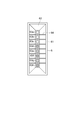
- FIG. 1 is a schematic view showing an ink jet recording apparatus according to the embodiment
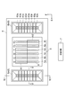
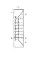
- FIG. 2 is an enlarged view of the carriage shown in FIG.
- the inkjet recording apparatus 1 according to the present embodiment includes a flat bed 2 on which a medium M as a recording medium is placed, and a flat bed 2 disposed above the flat bed 2 in the sub-scanning direction F.
- the main scanning direction S is a direction in which the carriage 4 is reciprocated to record an image band on the medium M.
- the sub-scanning direction F is a direction in which the Y bar 3 is moved relative to the medium M. This is a direction in which the position of the band recorded on the medium M is shifted.
- the ink jet recording apparatus 1 is configured to reciprocate the carriage 4 in the main scanning direction S while conveying the Y bar 3 by a predetermined pass width in the sub scanning direction F under the control of the control unit 7.
- An ultraviolet curable ink is ejected from the inkjet head 5 and an ultraviolet ray is irradiated from the ultraviolet irradiation device 6, whereby an image is recorded on the medium.
- the front in the main scanning direction S is the direction in which the carriage 4 moves in the main scanning direction S (left side in FIG. 1)
- the rear in the main scanning direction S is the carriage 4 in the main scanning direction S.
- the direction of movement in the opposite direction (right side in FIG. 1).
- the front in the sub scanning direction F is a direction in which the Y bar 3 moves in the sub scanning direction F (upper side in FIG. 1)
- the rear in the sub scanning direction F is the Y bar 3 in the sub scanning direction.
- the direction of movement in the direction opposite to F (the lower side in FIG. 1).
- the Y bar 3 conveys the carriage 4 with respect to the flat bed 2 in the sub-scanning direction F.
- the Y bar 3 is movably mounted on a guide rail (not shown) extending in the sub-scanning direction F, and is driven by a drive mechanism (not shown) such as a drive motor, so that it follows the guide rail. Reciprocal movement in the sub-scanning direction F is possible.
- the rear side of the sub-scanning direction F is the upstream side of the sub-scanning direction F of the Y bar 3
- the front side of the sub-scanning direction F is the sub-scanning direction of the Y bar 3. Downstream of F.
- the front side in the sub-scanning direction F is the upstream side of the Y-bar 3 in the sub-scanning direction F
- the rear side in the sub-scanning direction F is the Y-bar 3 side.
- the carriage 4 conveys the inkjet head 5 and the ultraviolet irradiation device 6 in the main scanning direction S with respect to the flat bed 2.
- the carriage 4 is movably held on a guide rail 9 extending in the main scanning direction S, and is driven by a driving mechanism (not shown) such as a driving motor, so that the main scanning direction S along the guide rail 9 is driven. It is possible to move back and forth.
- the rear side of the main scanning direction S is the upstream side of the main scanning direction S of the carriage 4
- the front side of the main scanning direction S is the downstream side of the main scanning direction S of the carriage 4.
- the carriage 4 moves backward in the main scanning direction S
- the front side of the main scanning direction S is the upstream side of the main scanning direction S of the carriage 4
- the rear side of the main scanning direction S is the main scanning direction of the carriage 4. S downstream.
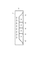
- the inkjet heads 5a to 5f are provided along the main scanning direction S. From the front side in the main scanning direction S, the inkjet head 5a, the inkjet head 5b, the inkjet head 5c, the inkjet head 5d, the inkjet head 5e, and the inkjet head 5f. They are arranged in order. Since each inkjet head 5 is mounted on the carriage 4, it is possible to eject ultraviolet curable ink while moving in the main scanning direction S as the carriage 4 is scanned.
- Each ink jet head 5 is formed with a plurality of ink nozzles 8 for discharging ultraviolet curable ink as ink droplets.
- the plurality of ink nozzles 8 are arranged to extend in the sub-scanning direction F to form a nozzle row.
- Colored ultraviolet curable ink (hereinafter also referred to as “color ink”) is ejected from the ink nozzles 8 of the inkjet heads 5a to 5d arranged on the front side in the main scanning direction S and arranged on the rear side in the main scanning direction S.
- translucent ultraviolet curable ink hereinafter also referred to as “clear ink” is ejected.
- black (K) color ink is ejected from each ink nozzle 8 of the inkjet head 5a
- cyan (C) color ink is ejected from each ink nozzle 8 of the inkjet head 5b.
- Magenta (M) color ink is ejected from each ink nozzle 8 of 5c
- yellow (Y) color ink is ejected from each ink nozzle 8 of the inkjet head 5d.
- clear ink (CL) is ejected from each ink nozzle 8 of the inkjet heads 5e and 5f.
- color ink is ejected only from the ink nozzles 8 in the first ejection region A1 arranged in the front half in the sub-scanning direction F. Color ink is not ejected from the ink nozzles 8 arranged in the rear half.
- clear ink is ejected only from the ink nozzles 8 in the second ejection region A2 arranged in the rear half in the sub-scanning direction F. Clear ink is not ejected from the ink nozzles 8 arranged in the front half.
- the color ink discharged from the first discharge area A1 of the inkjet heads 5a to 5d is applied to the medium M placed on the flat bed 2.
- Ink droplets are recorded, and then the clear ink droplets ejected from the second ejection areas A2 of the inkjet heads 5e and 5f are recorded on the surface (upper layer) of the color ink.
- the ultraviolet irradiation device 6 a is arranged in front of the inkjet head 5 in the main scanning direction S, and the ultraviolet irradiation device 6 b is arranged in the main scanning direction S behind the inkjet head 5.
- the ultraviolet irradiating device 6a and the ultraviolet irradiating device 6b are configured in the same way, and irradiate the ultraviolet curable ink recorded on the medium with ultraviolet rays to cure the ultraviolet curable ink.
- the ultraviolet irradiation device 6a and the ultraviolet irradiation device 6b are collectively described as the ultraviolet irradiation device 6. Since the ultraviolet irradiation device 6 is mounted on the carriage 4, it is possible to emit ultraviolet rays while moving in the main scanning direction S as the carriage 4 is scanned.
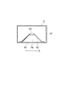
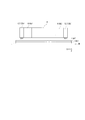
- FIG. 3 is a bottom perspective view of the ultraviolet irradiation device
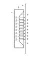
- FIG. 4 is a bottom perspective view of the ultraviolet irradiation device with the partition plate removed.
- 5 is a cross-sectional view taken along line VV shown in FIG. 2
- FIG. 6 is a cross-sectional view taken along line VI-VI shown in FIG.
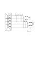
- the ultraviolet irradiation device 6 includes a main body 61, a recess 62 formed on the lower surface on the side facing the medium M of the main body 61 facing the flat bed 2, and a recess 62.
- a plurality of UVLEDs 63 (ultraviolet light emitting diodes) arranged and a plurality of partition plates 64 arranged in the recess 62 are provided.
- the concave portion 62 reflects ultraviolet rays emitted from the UVLED 63 and spreading in the main scanning direction S toward the flat bed 2 in the vertical direction, and is subjected to a mirror surface treatment.
- the recess 62 is formed in a mortar shape elongated in the sub-scanning direction F. More specifically, the recess 62 is a truncated pyramid having a small bottom and a large opening side, and is formed in an umbrella shape in which each inner side surface extends at an angle of about 60 ° with respect to the vertical downward direction. For this reason, the recess 62 has a trapezoid with a narrow cross section in the main scanning direction S (see FIG. 5) and a trapezoid with a wide cross section in the sub-scanning direction F (see FIG. 6).
- a transparent cover 65 for example, quartz glass having ultraviolet transmissivity is fitted into the rectangular opening formed in the lower end surface of the recess 62 from below in the vertical direction. Thereby, it is possible to transmit the ultraviolet rays emitted from the UVLED 63 while closing the opening of the recess 62.
- the UVLEDs 63 are arranged at the most concave position at the center bottom of the concave portion 62, and are arranged in a line at equal intervals along the sub-scanning direction F. In the main scanning direction S, a plurality of UVLEDs 63 are arranged at positions corresponding to the first ejection area A1 of the inkjet heads 5a to 5d and the second ejection area A2 of the inkjet heads 5e and 5f.
- the inkjet recording apparatus 1 when multi-pass printing is performed by the inkjet recording apparatus 1, it is possible to record a plurality of bands by ink droplets ejected from the first ejection area A1 and the second ejection area A2 in a plurality of passes. For this reason, the first discharge area A1 and the second discharge area A2 become pass areas.
- UVLEDs 63 are mounted on the ultraviolet irradiation device 6, and four UVLEDs 63 are arranged in the main scanning direction S at positions corresponding to the first ejection region A1 and the second ejection region A2, respectively. To do.
- arranging the four UVLEDs 63 at positions corresponding to the first ejection area A1 means that the ink droplets ejected from the first ejection area A1 and landed on the medium M are four UVLEDs 63, that is, UVLEDs 63a, 63b, 63c, 63d is an arrangement relationship that can be cured, and in the case where a band is recorded by ejecting ink droplets from the first ejection area A1 while moving the carriage 4 in the main scanning direction S, the first ejection area.
- UVLEDs 63a, 63b, 63c, and 63d are arranged at positions where the band recorded by A1 can be irradiated with ultraviolet rays and cured.
- arranging four UVLEDs 63 at positions corresponding to the second ejection area A2 means that the ink droplets ejected from the second ejection area A2 and landed on the medium M are four UVLEDs 63, that is, UVLEDs 63e and 63f. , 63g, and 63h, the second discharge area A2 when the band is recorded by discharging ink droplets from the second discharge area A2 while moving the carriage 4 in the main scanning direction S.
- the UVLEDs 63e, 63f, 63g, and 63h are arranged at positions where the bands recorded by the above can be cured by irradiating with ultraviolet rays.
- the UVLED 63 arranged at the position corresponding to the first ejection area A1 is arranged in the order of the UVLED 63a, UVLED 63b, UVLED 63c, UVLED 63d from the front side in the sub scanning direction F, and the UVLED 63 arranged at the position corresponding to the second ejection area A2 is
- the UVLED 63e, the UVLED 63f, the UVLED 63g, and the UVLED 63h are arranged in this order from the front side in the sub scanning direction F. Therefore, when performing 8-pass multi-pass printing, one UVLED 63 is associated with one band, and when performing 4-pass multi-pass printing, two UVLEDs 63 are associated with one band. When performing multi-pass printing of a pass, four UVLEDs 63 are associated with one band.
- each UVLED 63 emits highly directional ultraviolet rays, the illuminance in the direction inclined by 60 ° with respect to the vertical direction is about 50% with respect to the illuminance in the vertical direction.
- the partition plate 64 controls the irradiation of ultraviolet rays in the sub-scanning direction F, and is formed in a flat plate shape standing in the vertical direction and extending in the main scanning direction S.
- the partition plate 64 is formed in a trapezoidal shape having substantially the same dimension as the cross section of the recess 62 in the main scanning direction S, and is in close contact with the inner surface of the recess 62 and extends from the bottom of the recess 62 to the vicinity of the opening. . For this reason, by attaching the partition plate 64 to the recessed portion 62, the space between the recessed portion 62 and the partition plate 64 is closed without a gap, and the ultraviolet light does not leak from the space between the recessed portion 62 and the partition plate 64. Function.
- the partition plate 64 preferably extends to the opening side of the recess 62 as long as it does not hinder the fitting of the cover 65 into the opening of the recess 62.
- the cover 65 is fitted into the opening of the recess 62. It is good also as a dimension which the partition plate 64 just contact
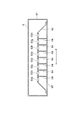
- the partition plate 64 is disposed between the adjacent UV LEDs 63 and is attached to the ultraviolet irradiation device 6 so as to be individually insertable / removable. For this reason, a maximum of seven partition plates 64 are attached to the ultraviolet irradiation device 6 on which eight UVLEDs 63 are mounted (see FIG. 3), and all the partition plates 64 can be removed (see FIG. 3). 4).
- FIG. 7 is a view showing the irradiation direction of ultraviolet rays when a partition plate is attached between all the UV LEDs.
- the ultraviolet rays emitted from the UVLEDs 63 travel only downward in the vertical direction, and vertically below the adjacent UVLEDs 63 in the sub-scanning direction F. Is prevented from entering For this reason, the medium M is irradiated with ultraviolet rays only from the UVLEDs 63 arranged vertically above, and is not irradiated with the UVLEDs 63 arranged adjacently before and after the sub-scanning direction F.
- the control unit 7 controls the Y bar 3, the carriage 4, the inkjet head 5, the ultraviolet irradiation device 6, and the like to perform print control for recording an image or the like on the medium M placed on the flat bed 2.
- the control unit 7 records the image quality of matte, glossy, and thick coating by these controls.
- a matte image forming mode is a matte image quality mode
- a glossy image forming mode is a gross image quality mode
- a single-layer gross image quality mode that performs only recording of gross image quality without forming an image
- the mode for forming the image is referred to as a thick image quality mode.
- the control unit 7 is configured mainly by a computer including a CPU, a ROM, and a RAM, for example, and each control of the control unit 7 described above reads predetermined computer software on the CPU or RAM, and controls the CPU. It is realized by operating under
- the dust removing means causes a dust removing action on the medium M by removing dust from the recording medium (here, the medium M) or preventing dust from entering the medium M, This mechanism prevents dust from adhering to ink droplets.
- the medium M the recording medium
- This mechanism prevents dust from adhering to ink droplets.
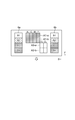
- FIG. 24 is a schematic diagram illustrating an example in which the inkjet recording apparatus 1 includes an air suction unit 12 that sucks air on the medium M side as a first example of the dust removing unit.
- the air suction means 12 is provided on the carriage 4.
- the air suction means 12 is preferably arranged at the front end or rear end of the carriage 4 in the scanning direction (here, the main scanning direction S).
- An example in the case of being provided at the front end is the air suction means 12 (12a), and an example in the case of being provided at the rear end is the air suction means 12 (12b). Is shown.
- the air suction means 12 As the air suction means 12, a known suction mechanism or decompression mechanism such as a fan or a pump can be employed. As an action thereof, the air on the medium M is sucked by operating the air suction means 12 before, after, or after the ink droplet of clear ink is ejected from the carriage 4. Thus, dust existing in the air can be sucked. Therefore, it is possible to suppress the adhesion of dust before the ink droplets of the clear ink ejected on the medium M are cured by the ultraviolet irradiation device 6.
- FIG. 25A and FIG. 25B are blower means for the ink jet recording apparatus 1 to blow gas (for example, air) to the medium M side as a second embodiment of the dust removing means.
- gas for example, air
- FIG. 25A and 25B the air blowing means 14 (14 a and 14 b) is provided on the carriage 4.
- the air blowing unit 14 is disposed at the front end or the rear end of the carriage 4 in the scanning direction (here, the main scanning direction S).
- FIG. 25A An example in the case of being provided at the front end is the air blowing means 14 (14a), and an example in the case of being provided at the rear end is the air blowing means 14 (14b), both of which are shown in one figure (in FIG. 25A) for convenience of explanation. I am doing.
- the air blowing means 14 a known air blowing mechanism such as a fan can be adopted. As its action, before the ink droplet of clear ink is ejected from the carriage 4, the ejected state or after it is ejected, the air blowing means 14 is operated to blow out the gas onto the medium M. Dust present in the air on the medium M can be removed. Therefore, it is possible to suppress the adhesion of dust before the ink droplets of the clear ink ejected on the medium M are cured by the ultraviolet irradiation device 6.
- the air blowing means 14 is preferably configured to blow out gas in a direction orthogonal to the scanning direction (here, the main scanning direction S). According to this, by blowing the gas in a direction orthogonal to the main scanning direction S, the gas ejected to the ink droplet before being ejected and landed does not directly hit, so that the flight bending of the ink droplet can be suppressed.
- the air blowing means 14 (14c) may be arranged at the front end of the carriage 4 in the scanning direction (here, the sub-scanning direction F). According to this, it is possible to remove the dust present in the air on the medium M by blowing the gas forward in the sub-scanning direction F.
- FIG. 27 is a schematic diagram illustrating an example in which the inkjet recording apparatus 1 includes a blowing unit 16 that blows out gas (for example, air) on the medium M side as a third embodiment of the dust removing unit. As shown in FIG. 27, the air blowing means 16 is provided on the Y bar 3.
- gas for example, air
- the air blowing means 16 can employ a known air blowing mechanism, such as a fan, as with the air blowing means 14. As its action, before the ink droplet of clear ink is ejected from the carriage 4, the ejected state or after the ejection, the air blowing means 16 is operated to blow out gas onto the medium M to Dust present in the air on the medium M can be removed. Therefore, it is possible to suppress the adhesion of dust before the ink droplets of the clear ink ejected on the medium M are cured by the ultraviolet irradiation device 6.
- a known air blowing mechanism such as a fan
- the air blowing means 16 may be arranged in a portion (for example, the flat bed 2) other than the Y bar 3 and the carriage 4 in the ink jet recording apparatus 1 (not shown).
- FIG. 28 is a schematic diagram showing an example in which the inkjet recording apparatus 1 includes an air suction means 18 for sucking air on the medium M side as a fourth embodiment of the dust removing means. As shown in FIG. 28, the air suction means 18 is provided on the Y bar 3.
- the air suction means 18 can employ a known suction mechanism or pressure reduction mechanism, such as a fan or a pump, similarly to the air suction means 12. As an action thereof, the air on the medium M is sucked by operating the air suction means 12 before, after, or after the ink droplet of clear ink is ejected from the carriage 4. Thus, dust existing in the air can be sucked. Therefore, it is possible to suppress the adhesion of dust before the ink droplets of the clear ink ejected on the medium M are cured by the ultraviolet irradiation device 6.
- a known suction mechanism or pressure reduction mechanism such as a fan or a pump
- the air suction means 18 may be arranged in a portion (for example, the flat bed 2) other than the Y bar 3 and the carriage 4 in the ink jet recording apparatus 1 (not shown).
- the following effects are exhibited. That is, even when a predetermined time elapses after the ink droplet of the clear ink has landed on the medium M and until the clear ink is cured, dust adheres to the surface of the ink droplet during the predetermined time. It is possible to prevent the image quality of tone printing from deteriorating. As a result, it is possible to maintain a high gloss image quality and realize a sufficiently glossy recording.
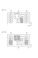
- First discharge area A1-b the second half of sub-scanning direction F in the second discharge area A2 is “second discharge area A2-a”, and the second half of sub-scanning direction F in the second discharge area A2 is “first”.
- the two discharge areas A2-b ′′ are assumed.
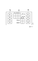
- the concave portion 62 includes an area B1 in which the UVLED 63a and the UVLED 63b are arranged, an area B2 in which the UVLED 63c and the UVLED 63d are arranged, an area B3 in which the UVLED 63e and the UVLED 63f are arranged, and a UVLED 63g.
- the area is divided into four areas: an area B4 where the UVLED 63h is arranged. Therefore, as shown in FIG.
- the area B1 corresponds to one band of the first ejection area A1-a
- the area B2 corresponds to one band of the first ejection area A1-b
- the area B3 Corresponds to one band of the second ejection area A2-a
- area B4 corresponds to one band of the second ejection area A2-b
- the area B1 corresponds to one band of the first ejection area A1-a means that the ink droplets ejected from the first ejection area A1-a and landed on the medium M are two UVLEDs, that is, UVLED 63a and 63b indicates that the area B2 corresponds to one band of the first ejection area A1-b.
- Ink droplets ejected from the first ejection area A1-b and landed on the medium M are collected.
- An arrangement relationship that can be cured by two UVLEDs, that is, the UVLEDs 63c and 63d, and that the area B3 corresponds to one band of the second discharge area A2-a is discharged from the second discharge area A2-a.
- Ink droplets ejected from the second ejection area A2-b and landed on the medium M can be cured by two UVLEDs, that is, UVLEDs 63g and 63h. It is a serious arrangement relationship. Therefore, when recording a band by discharging ink droplets from the first discharge area A1 while moving the carriage 4 in the main scanning direction S, the band recorded by the first discharge area A1-a is irradiated with ultraviolet rays.
- the UVLEDs 63a and 63b in the area B1 are arranged at the position where they can be cured, and the UVLEDs 63c and 63d in the area B2 are arranged at a position where the bands recorded by the first discharge area A1-b can be irradiated with ultraviolet rays.
- the UV LEDs 63e and 63f in the area B3 are arranged at positions where the band recorded by the second discharge area A2-a can be irradiated with ultraviolet rays and cured, and the band recorded by the second discharge area A2-b
- the UVLEDs 63g and 63h in the area B4 are arranged at positions where they can be irradiated and cured.
- a processing unit (not shown) constituted by a CPU or the like causes the Y bar 3, the carriage 4, the inkjet head 5, the ultraviolet irradiation device 6, etc.
- the following processing is performed by centralized control.
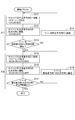
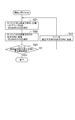
- FIG. 10 is a flowchart illustrating a print processing method in the mat image quality mode.
- FIG. 11 is a conceptual diagram showing an example of the operation mode of the carriage in the mat image quality mode.
- a thick arrow indicates the moving direction of the Y bar 3 in the sub-scanning direction F. That is, FIG. 11 shows that the Y bar 3 moves in the sub-scanning direction F.
- the ultraviolet curable ink is ejected only when the carriage 4 is moved forward in the main scanning direction S, and the ultraviolet curable ink is used when the carriage 4 is moved backward in the direction opposite to the main scanning direction S. It shall not be discharged.
- the medium M is placed on the flat bed 2, and the Y bar 3 is set at the rear end portion (print start position) in the sub-scanning direction F in the recording area of the medium M.
- step S1 ink droplets of color ink are ejected from the first ejection area A1-a and the area of the ultraviolet irradiation device 6b.
- the UV LEDs 63a and 63b arranged in B1 are turned on (step S1).
- step S2 when the carriage 4 is moved backward in the direction opposite to the main scanning direction S, the UVLED 63 for irradiating the band recorded in step S1 with ultraviolet rays is turned on (step S2).
- the UV LEDs 63 of both the ultraviolet irradiation device 6a and the ultraviolet irradiation device 6b may be turned on, or one of the UV LEDs 63 may be turned on.
- the first-pass recording is performed with the color ink ejected from the first ejection area A1-a, and this color ink is irradiated with ultraviolet rays immediately after landing on the medium M and hardened into a granular shape.
- step S3 When the reciprocation of the carriage 4 in the main scanning direction S is completed, it is next determined whether or not the Y bar 3 has been conveyed a predetermined number of times in the sub-scanning direction F (step S3).
- the print data is divided into a plurality of bands and recorded while the Y bar 3 is sequentially conveyed in the sub-scanning direction F.
- two-pass recording with color ink is performed in the first two scans
- two-pass recording with clear ink is performed in the subsequent two scans, so that recording in each band is completed in four scans.
- step S3 it is determined in step S3 that the Y bar 3 has been conveyed a predetermined number of times in the sub-scanning direction F after the fourth scan, and the predetermined number of times that the Y bar 3 is conveyed in the sub-scanning direction F in the mat image quality mode is Data division number + 3 times.
- step S3 NO
- step S4 Since the current scan is the first scan, it is determined that the Y bar 3 is not conveyed a predetermined number of times in the sub-scanning direction F (step S3: NO), and the Y bar 3 is moved by one band in the sub-scanning direction F. Only (pass width) is conveyed (step S4), and the process returns to step S1. Then, since the carriage 4 mounted on the Y bar 3 also moves by one band in the sub-scanning direction F, the inkjet head 5 and the ultraviolet irradiation device 6 are associated with the next pass line, and the recording position on the medium is set to the sub-scanning direction. It advances forward in the scanning direction F.
- step S2 when the carriage 4 is moved forward in the main scanning direction S, ink droplets of color ink are ejected from the first ejection area A1-a, and the UVLED 63a disposed in the area B1 of the ultraviolet irradiation device 6b and 63b is turned on, and ink droplets of color ink are discharged from the first discharge area A1-b, and the UV LEDs 63c and 63d arranged in the area B2 of the ultraviolet irradiation device 6b are turned on (step S1). Further, when the carriage 4 is moved backward in the direction opposite to the main scanning direction S, the UVLED 63 for irradiating the band recorded in step S1 with ultraviolet rays is turned on (step S2).
- the UV LEDs 63 of both the ultraviolet irradiation device 6a and the ultraviolet irradiation device 6b may be turned on, or one of the UV LEDs 63 may be turned on.
- the first pass printing is performed with the color ink ejected from the first ejection area A1-a.
- step S3 NO
- step S4 the process returns to step S1.
- the carriage 4 mounted on the Y bar 3 also moves by one band in the sub-scanning direction F
- the inkjet head 5 and the ultraviolet irradiation device 6 are associated with the next pass line, and the recording position on the medium is set to the sub-scanning direction. It advances forward in the scanning direction F.
- ink droplets of color ink are ejected from the first ejection areas A1-a and A1-b, and areas B1 and B2 of the ultraviolet irradiation device 6b are ejected.
- the UVLEDs 63a to 63d disposed in the LED are turned on, the ink droplets of the clear ink are ejected from the second ejection region A2-a, and the UVLEDs 63e and 63f disposed in the area B3 of the ultraviolet irradiation device 6b are lit (step) S1).
- the UVLED 63 for irradiating the band recorded in step S1 with ultraviolet rays is turned on (step S2).
- the UV LEDs 63 of both the ultraviolet irradiation device 6a and the ultraviolet irradiation device 6b may be turned on, or one of the UV LEDs 63 may be turned on.
- the first pass recording is performed with the color ink ejected from the first ejection area A1-a, and in the same manner as in the second scan, the first ejection area A1 is performed.
- the second pass printing is performed with the color ink ejected from -b.
- step S3 NO
- step S4 the process returns to step S1.
- the carriage 4 mounted on the Y bar 3 also moves by one band in the sub-scanning direction F
- the inkjet head 5 and the ultraviolet irradiation device 6 are associated with the next pass line, and the recording position on the medium is set to the sub-scanning direction. It advances forward in the scanning direction F.
- the UVLEDs 63a to 63d disposed in the light are turned on, the ink droplets of the clear ink are ejected from the second ejection region A2-a, the UVLEDs 63e and 63f disposed in the area B3 of the ultraviolet irradiation device 6b are turned on, and the first Ink droplets of clear ink are ejected from the two ejection areas A2-b, and the UV LEDs 63g and 63h arranged in the area B4 of the ultraviolet irradiation device 6b are turned on (step S1).
- the UVLED 63 for irradiating the band recorded in step S1 with ultraviolet rays is turned on (step S2).
- the UV LEDs 63 of both the ultraviolet irradiation device 6a and the ultraviolet irradiation device 6b may be turned on, or one of the UV LEDs 63 may be turned on.
- the fourth pass is recorded by the clear ink discharged from the second discharge area A2-b on the band where the third pass recording is performed by the clear ink discharged from the second discharge area A2-a.
- the first pass printing is performed with the color ink ejected from the first ejection area A1-a, and in the same manner as in the second scan, the first ejection area A1 is performed.
- the second pass recording is performed with the color ink ejected from -b, and the third pass recording is performed with the clear ink ejected from the second ejection area A2-a, as in the third scan.
- the current scanning is the fourth scanning, so it is next determined whether or not the Y bar 3 has been conveyed a predetermined number of times in the sub-scanning direction F (step). S3).
- step S3 If it is determined that the Y bar 3 has not been conveyed a predetermined number of times in the sub-scanning direction F (step S3: NO), the Y bar 3 is conveyed by one band (pass width) in the sub-scanning direction F. (Step S4), the process returns to Step S1. Then, since the carriage 4 moves by one band in the sub-scanning direction F, the inkjet head 5 and the ultraviolet irradiation device 6 are associated with the next pass line, and the recording position on the medium is advanced forward in the sub-scanning direction F. . The above-described steps S1 to S3 are repeated until it is determined in step S3 that the Y bar 3 has been conveyed a predetermined number of times in the sub-scanning direction F.
- step S3 YES
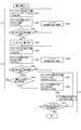
- FIG. 12 is a flowchart illustrating a print processing method in the gross image quality mode.
- 13A and 13B are conceptual diagrams illustrating an example of an operation mode of the carriage in the gross image quality mode.
- a thick arrow indicates a moving direction of the Y bar 3 in the sub-scanning direction F. That is, FIG. 13A shows that the Y bar 3 moves in the sub-scanning direction F, and FIG. 13B shows that the Y bar 3 moves in the direction opposite to the sub-scanning direction F.
- the ultraviolet curable ink is ejected only when the carriage 4 moves forward in the main scanning direction S, and the ultraviolet curable ink is used when the carriage 4 moves backward in the direction opposite to the main scanning direction S. It shall not be discharged.
- step S11 to step S14 the Y bar 3 is sequentially conveyed in the sub-scanning direction F to record an image with color ink.
- steps S15 to S18 the Y bar 3 is sequentially conveyed in the direction opposite to the sub-scanning direction F to coat the image with clear ink. That is, in the gross image quality mode, an image is recorded with color ink in the forward path of the Y bar 3 conveyed in the sub-scanning direction F, and clear ink is used in the return path of the Y bar 3 conveyed in the direction opposite to the sub-scanning direction F. Perform image coating.
- Steps S11 to S14 are referred to as an image recording process ⁇ 1, and an example of the operation mode of the carriage in the image recording process ⁇ 1 is shown in FIG. 13A.
- Steps S15 to S18 are referred to as a coating process ⁇ 2, and an example of the operation mode of the carriage in the coating process ⁇ 2 is shown in FIG. 13B.
- the medium M is placed on the flat bed 2, the Y bar 3 is set at the rear end portion (printing start position) in the sub scanning direction F in the recording area of the medium M, and the Y bar 3 is sequentially moved in the sub scanning direction F.
- the image recording process ⁇ 1 is performed while being conveyed.
- step S11 when the carriage 4 is moved forward in the main scanning direction S, ink droplets of color ink are ejected from the first ejection area A1-a and ultraviolet rays are ejected.
- the UV LEDs 63 of both the ultraviolet irradiation device 6a and the ultraviolet irradiation device 6b may be turned on, or one of the UV LEDs 63 may be turned on.
- the first-pass recording is performed with the color ink ejected from the first ejection area A1-a, and this color ink is irradiated with ultraviolet rays immediately after landing on the medium M and hardened into a granular shape.
- step S13 When the reciprocation of the carriage 4 in the main scanning direction S is completed, it is next determined whether or not the Y bar 3 has been conveyed a predetermined number of times in the sub-scanning direction F (step S13).
- the print data is divided into a plurality of bands and recorded while sequentially transporting the Y bar 3 in the sub-scanning direction F.
- Each band is subjected to two-pass printing with color ink and ultraviolet irradiation in the first two scans, and further irradiated with ultraviolet rays in the subsequent two scans, so that each band is subjected to four scans (four passes). Recording is complete.
- step S13 it is determined in step S13 that the Y bar 3 has been conveyed a predetermined number of times in the sub-scanning direction F after the fourth scan, and the predetermined number of times that the Y bar 3 is conveyed in the sub-scanning direction F in the image recording step ⁇ 1 is The number of print data divisions is +3.
- step S13 NO
- step S14 the process returns to step S11.
- step S11 the carriage 4 mounted on the Y bar 3 also moves by one band in the sub-scanning direction F
- the inkjet head 5 and the ultraviolet irradiation device 6 are associated with the next pass line, and the recording position on the medium is set to the sub-scanning direction. It advances forward in the scanning direction F.
- ink droplets of color ink are ejected from the first ejection area A1-a, and the area B1 of the ultraviolet irradiation device 6b is ejected.
- the arranged UV LEDs 63a and 63b are turned on, and further, ink droplets of color ink are ejected from the first ejection area A1-b, and the UV LEDs 63c and 63d arranged in the area B2 of the ultraviolet irradiation device 6b are turned on (step S11). ).
- the UVLED 63 for irradiating the band recorded in step S11 with ultraviolet rays is turned on (step S12).
- the UV LEDs 63 of both the ultraviolet irradiation device 6a and the ultraviolet irradiation device 6b may be turned on, or one of the UV LEDs 63 may be turned on.
- the color ink ejected from the first ejection area A1-b is applied to the band on which the first pass recording has been performed by the color ink ejected from the first ejection area A1-a.
- step S13 NO
- step S14 the process returns to step S11.
- step S11 the carriage 4 mounted on the Y bar 3 also moves by one band in the sub-scanning direction F
- the inkjet head 5 and the ultraviolet irradiation device 6 are associated with the next pass line, and the recording position on the medium is set to the sub-scanning direction. It advances forward in the scanning direction F.
- step S11 when the carriage 4 moves forward in the main scanning direction S, ink droplets of color ink are ejected from the first ejection areas A1-a and A1-b, and the ultraviolet irradiation device 6b.
- the UVLEDs 63a to 63d arranged in the areas B1 and B2 are turned on, and the UVLEDs 63e and 63f arranged in the area B3 are turned on (step S11).
- step S12 when the carriage 4 is moved backward in the direction opposite to the main scanning direction S, the UVLED 63 for irradiating the band recorded in step S11 with ultraviolet rays and the UVLEDs 63e and 63f arranged in the area B3 are turned on (step S12).
- the second pass recording is performed by the color ink ejected from the first ejection region A1-b in the previous scan.
- the color ink recorded in the band is further cured.
- the third scan as in the first scan, the first pass recording is performed with the color ink ejected from the first ejection area A1-a, and in the same manner as in the second scan, the first ejection area A1 is performed.
- the second pass printing is performed with the color ink ejected from -b.
- step S13 NO
- step S14 the process returns to step S11.
- step S11 the carriage 4 mounted on the Y bar 3 also moves by one band in the sub-scanning direction F
- the inkjet head 5 and the ultraviolet irradiation device 6 are associated with the next pass line, and the recording position on the medium is set to the sub-scanning direction. It advances forward in the scanning direction F.
- ink droplets of color ink are ejected from the first ejection areas A1-a and A1-b, and the ultraviolet irradiation device 6b.
- the UVLEDs 63a to 63d arranged in the areas B1 and B2 are turned on, the UVLEDs 63e and 63f arranged in the area B3 are turned on, and the UVLEDs 63g and 63h arranged in the area B4 are turned on (step S11).
- the UVLED 63 for irradiating the band recorded in step S11 with ultraviolet rays and the UVLEDs 63e to 63h arranged in the areas B3 and B4 are turned on (step S12). . Then, ultraviolet rays were irradiated from the UVLEDs 63g and 63h arranged in the area B4 as the fourth pass to the band irradiated with the ultraviolet rays from the UVLEDs 63e and 63f arranged in the area B3 in the previous scan, and recorded in the band.
- the color ink is further cured.
- the first pass printing is performed with the color ink ejected from the first ejection area A1-a, and in the same manner as in the second scan, the first ejection area A1 is performed.
- the second-pass recording is performed with the color ink ejected from -b, and the UVLEDs 63e and 63f arranged in the area B4 are irradiated with ultraviolet rays on the band where the second-pass recording is performed, as in the third scan.
- the current scanning is the fourth scanning of the image recording step ⁇ 1, so whether or not the Y bar 3 has been conveyed in the sub scanning direction F a predetermined number of times. Is determined (step S13).
- step S13 If it is determined that the Y bar 3 has not been conveyed a predetermined number of times in the sub-scanning direction F (step S13: NO), the Y bar 3 is conveyed by one band (pass width) in the sub-scanning direction F. (Step S14), the process returns to Step S11. Then, since the carriage 4 moves by one band in the sub-scanning direction F, the inkjet head 5 and the ultraviolet irradiation device 6 are associated with the next pass line, and the recording position on the medium is advanced forward in the sub-scanning direction F. . The above-described steps S11 to S13 are repeated until it is determined in step S13 that the Y bar 3 has been conveyed a predetermined number of times in the sub-scanning direction F.
- the UVLED 63 for irradiating the band recorded in step S11 with ultraviolet rays and the UVLEDs 63e to 63h arranged in the areas B3 and B4 are turned on (step S12).
- the second band is printed with the color ink discharged from the first discharge area A1-a to the last band where the first pass recording is performed with the color ink discharged from the first discharge area A1-a. Is recorded.
- the UVLEDs 63e and 63f arranged in the area B3 are irradiated with ultraviolet rays to the band on which the second pass recording has been performed by the color ink ejected from the first ejection area A1-b in the previous scan, and the area B3 is irradiated.
- the bands irradiated with ultraviolet rays from the arranged UVLEDs 63e and 63f are irradiated with ultraviolet rays from the UVLEDs 63g and 63h arranged in the area B4.
- step S11 the UV LEDs 63e to 63h arranged in the areas B3 and B4 are turned on.
- the UV LEDs 63e to 63h arranged in the areas B3 and B4 are turned on (step S12).
- ultraviolet rays are irradiated from the UV LEDs 63e and 63f arranged in the area B3 to the last band on which the second pass recording is performed by the color ink ejected from the first ejection area A1-b in the previous scan. Further, ultraviolet rays are irradiated from the UVLEDs 63g and 63h arranged in the area B4 to the band irradiated with ultraviolet rays from the UVLEDs 63e and 63f arranged in the area B3 in the previous scan.
- the discharge of the color ink from the first discharge areas A1-a and A1-b is stopped and arranged in the area B3.
- the UV LEDs 63e and 63f are turned off, and only the UV LEDs 63g and 63h arranged in the area B4 are turned on (step S11). Further, when the carriage 4 is moved backward in the direction opposite to the main scanning direction S, only the UV LEDs 63g and 63h arranged in the area B4 are turned on (step S12).
- the last band irradiated with ultraviolet rays from the UVLEDs 63e and 63f arranged in the area B3 in the previous scan is irradiated with ultraviolet rays from the UVLEDs 63g and 63h arranged in the area B4.
- the image recording process ⁇ 1 is completed in a state where the second ejection area A2-b is arranged in the pass line of the final band.
- step S13 YES
- the coating process ⁇ 2 is performed while sequentially conveying the Y bar 3 in the direction opposite to the sub-scanning direction F. Do.
- step S15 when moving the carriage 4 in the main scanning direction S, ink droplets of clear ink are ejected from the second ejection area A2-b, and ultraviolet irradiation is performed.
- step S16 when the carriage 4 is moved backward in the direction opposite to the main scanning direction S, the UV LEDs 63g and 63h arranged in the band where the clear ink is recorded in step S15 are turned off (step S16).
- the second ejection area A2-b is disposed on the pass line of the final band in the image recording process ⁇ 1.
- the fifth pass printing is performed with the clear ink ejected from the second ejection area A2-b in the last band of the image recording process ⁇ 1 and the band disposed most forward in the sub-scanning direction F.
- the UVLEDs 63g and 63h arranged in the area B4 for irradiating the band on which the clear ink discharged from the second discharge area A2-b is irradiated with the ultraviolet light are turned off, the fifth pass that has landed on the medium M
- the clear ink gradually gets wet and spreads without being cured, and the thickness is reduced, and the surface irregularities are smoothed.
- the UV LEDs 63a to 63d arranged in the areas B1 and B2 may be turned on or off.
- step S17 When the carriage 4 has been reciprocated in the main scanning direction S, it is next determined whether or not the Y bar 3 has been conveyed a predetermined number of times in the direction opposite to the sub-scanning direction F (step S17).
- the print data is divided into a plurality of bands and recorded while sequentially transporting the Y bar 3 in the direction opposite to the sub-scanning direction F.
- Each band is recorded in two passes with clear ink in the first two scans, and the clear ink recorded in each band is irradiated with ultraviolet rays in the subsequent two scans. Recording to the band is complete.
- step S17 it is determined in step S17 that the Y bar 3 has been conveyed a predetermined number of times in the direction opposite to the sub-scanning direction F after the fourth scan, and the Y bar 3 is conveyed in the direction opposite to the sub-scanning direction F in the coating process ⁇ 2.
- the predetermined number of times is the number of print data divisions + 3.
- step S17 NO
- step S18 Transport one band (pass width) in the opposite direction of the scanning direction F
- step S18 The process returns to step S15.
- the carriage 4 mounted on the Y bar 3 also moves by one band in the direction opposite to the sub-scanning direction F
- the inkjet head 5 and the ultraviolet irradiation device 6 are associated with the next pass line, and recording on the medium is performed.
- the position is advanced in the direction opposite to the sub-scanning direction F.
- ink droplets of clear ink are ejected from the second ejection area A2-b, and the ultraviolet irradiation device 6a and the ultraviolet irradiation device 6b.
- the UV LEDs 63g and 63h disposed in the area B4 are turned off, and ink droplets of clear ink are ejected from the second ejection area A2-a, and the UVLEDs 63g and 63h are disposed in the area B3 of the ultraviolet irradiation apparatus 6a and the ultraviolet irradiation apparatus 6b.
- the UV LEDs 63e and 63f are turned off (step S15).
- step S15 When the carriage 4 is moved backward in the direction opposite to the main scanning direction S, the UV LEDs 63e to 63h arranged in the band where the clear ink is recorded in step S15 are turned off (step S16). Then, in the first scan, the band in which the fifth pass recording is performed by the clear ink ejected from the second ejection area A2-b, the sixth pass by the clear ink ejected from the second ejection area A2-a. Recording is performed.
- the sixth pass that has landed on the medium M The clear ink gradually gets wet and spreads together with the clear ink of the fifth pass without being cured, and the thickness is reduced, and the surface unevenness is smoothed.
- the fifth pass printing is performed with the clear ink ejected from the second ejection area A2-b.
- the UV LEDs 63a to 63d arranged in the areas B1 and B2 may be turned on or off.
- step S17 NO
- step S18 the process returns to step S15.
- step S15 since the carriage 4 mounted on the Y bar 3 also moves by one band in the direction opposite to the sub-scanning direction F, the inkjet head 5 and the ultraviolet irradiation device 6 are associated with the next pass line, and recording on the medium is performed.
- the position is advanced in the direction opposite to the sub-scanning direction F.
- step S15 when moving the carriage 4 in the main scanning direction S, ink droplets of clear ink are ejected from the second ejection areas A2-a and A2-b, and the ultraviolet irradiation device 6a and The UV LEDs 63e to 63h arranged in the areas B3 and B4 of the ultraviolet irradiation device 6b are turned off, and the UV LEDs 63c and 63d arranged in the area B2 are turned on (step S15). Further, when the carriage 4 is moved backward in the direction opposite to the main scanning direction S, the UV LEDs 63c and 63d arranged in the area B2 are turned on (step S16).
- the UV LEDs 63c and 63d to be lit may be both the ultraviolet irradiation device 6a and the ultraviolet irradiation device 6b, or any one of them.
- the fifth pass printing is performed by the clear ink ejected from the second ejection area A2-b, and in the same manner as in the second scan, the second ejection area A2 is performed.
- Recording of the sixth pass is performed by the clear ink ejected from -a.
- the current scan is the third scan of the coating process ⁇ 2 (step S17: NO), so the Y bar 3 is moved to one band in the direction opposite to the sub-scanning direction F.
- the amount (pass width) is conveyed (step S18), and the process returns to step S15.
- the carriage 4 mounted on the Y bar 3 also moves by one band in the direction opposite to the sub-scanning direction F, the inkjet head 5 and the ultraviolet irradiation device 6 are associated with the next pass line, and recording on the medium is performed.
- the position is advanced in the direction opposite to the sub-scanning direction F.
- ink droplets of clear ink are ejected from the second ejection areas A2-a and A2-b, and the ultraviolet irradiation device 6a and
- the UVLEDs 63e to 63h arranged in the areas B3 and B4 of the ultraviolet irradiation device 6b are turned off, the UVLEDs 63c and 63d arranged in the area B2 are turned on, and the UVLEDs 63a and 63b arranged in the area B1 are turned on (step S15).
- the UV LEDs 63a to 63d arranged in the areas B1 and B2 are turned on (step S16).
- the UV LEDs 63a to 63d to be lit may be both the ultraviolet irradiation device 6a and the ultraviolet irradiation device 6b, or any one of them.
- the UV LED 63c and 63d arranged in the area B2 in the third scan before the first scan is irradiated with the ultraviolet light from the UV LEDs 63a and 63b arranged in the area B1 as the eighth pass, and the band is cleared. Curing of the ink is sufficiently accelerated.
- the fifth pass recording is performed by the clear ink ejected from the second ejection area A2-b, and in the same manner as in the second scan, the second ejection area A2 is performed.
- the sixth pass recording is performed by the clear ink ejected from -a, and the ultraviolet rays are irradiated to the band where the sixth pass recording was performed before the first scan, as in the third scan.
- step S17 When the reciprocating movement of the carriage 4 in the main scanning direction S is completed in this way, the current scanning is the fourth scanning of the coating process ⁇ 2, so the Y bar 3 is then moved in a direction opposite to the sub-scanning direction F. It is determined whether or not the sheet has been conveyed a number of times (step S17).
- step S17 If it is determined that the Y bar 3 has not been conveyed a predetermined number of times in the direction opposite to the sub-scanning direction F (step S17: NO), the Y bar 3 is moved by one band in the direction opposite to the sub-scanning direction F (pass width). ) Is conveyed (step S18), and the process returns to step S15. Then, since the carriage 4 moves by one band in the direction opposite to the sub-scanning direction F, the inkjet head 5 and the ultraviolet irradiation device 6 are associated with the next pass line, and the recording position on the medium is in the sub-scanning direction F. Proceed in the opposite direction. Steps S15 to S17 described above are repeated until it is determined in step S17 that the Y bar 3 has been conveyed a predetermined number of times in the direction opposite to the sub-scanning direction F.
- step S17 YES
- the smoothed clear ink is recorded on the upper layer of the image recorded on the medium M, the image can be given glossiness while ensuring the visibility of the image.
- the amount of light emitted from the UVLEDs 63 (UVLEDs 63c and 63d) arranged in the area B2 may be made smaller than the amount of light emitted from the UVLEDs (UVLEDs 63a and 63b) arranged in the area B1.
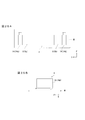
- Such light quantity control of ultraviolet rays can be realized by individually controlling lighting of each UVLED 63. For example, as shown in FIG. 14A, it can be realized by lowering the amount of light of the UVLEDs 63c and 63d by reducing the current applied to the UVLEDs 63c and 63d.
- the UVLED 63c is a UVLED 63a. And 63b can be turned on and the UVLED 63d can be turned off. In the case of ink having very good curability, only the UV LEDs 63a and 63b may be turned on.
- FIGS. 15A to 15C are views showing states of ink droplets that have landed on a medium.
- the color ink Ink1 is cured in a granular form as shown in FIG. 15A.
- the clear ink Ink2 does not cure immediately even when the ink droplet of the clear ink lands on the medium M. Therefore, as shown in FIGS. 15B and 15C, the clear ink Ink2 is between the color inks Ink1 cured in a granular form.
- the ink droplets are combined with adjacent ink droplets, and the thickness is reduced so as to spread out and the surface irregularities are smoothed.
- the color ink in the lower layer is flat, the movement of the clear ink in the upper layer is not activated, and the speed at which the clear ink is smoothed becomes slower. In this way, the color ink in the lower layer is cured in a granular form. By doing so, since the movement of the clear ink in the upper layer is activated, the speed at which the clear ink is smoothed can be increased. Since the clear ink Ink2 is sufficiently smoothed and then cured, a gloss image is obtained.
- steps S15 and S16 it is preferable to carry out a dust removing process using the dust removing means (the dust removing means and the dust removing action are described above). According to this, it is possible to prevent dust from adhering to the surface of the ink droplets of the clear ink after the clear ink is discharged onto the medium M and before the clear ink is irradiated with ultraviolet rays and cured. That is, since it is possible to prevent the image quality of the glossy printing from being deteriorated, it is possible to realize a high-quality gloss image with sufficient gloss.
- FIG. 16 is a flowchart illustrating a print processing method in the single-layer gloss image quality mode.
- FIG. 17 is a conceptual diagram illustrating an example of an operation mode of the carriage in the single-layer gloss image quality mode.
- the thick arrow indicates the moving direction of the Y bar 3 in the sub-scanning direction F. That is, FIG. 17 shows that the Y bar 3 moves in the direction opposite to the sub-scanning direction F.
- the ultraviolet curable ink is ejected only when the carriage 4 is moved forward in the main scanning direction S, and the ultraviolet curable type is used when the carriage 4 is moved backward in the direction opposite to the main scanning direction S. Ink is not ejected.
- the Y bar 3 is conveyed in the direction opposite to the sub-scanning direction F, and only the gloss image quality is recorded.
- the medium M is placed on the flat bed 2 and the Y bar 3 is set at the front end portion (printing start position) in the sub-scanning direction F in the recording area of the medium M.
- step S21 when the carriage 4 is moved forward in the main scanning direction S, ink droplets of clear ink are ejected from the second ejection area A2-b.
- step S22 when the carriage 4 is moved backward in the direction opposite to the main scanning direction S, the UV LEDs 63g and 63h arranged in the band where the clear ink is recorded in step S21 are turned off (step S22).
- the first pass printing is performed with the clear ink ejected from the second ejection area A2-b in the band arranged most forward in the sub-scanning direction F.
- the UVLEDs 63g and 63h arranged in the area B4 for irradiating the band on which the clear ink discharged from the second discharge area A2-b is irradiated with ultraviolet light are turned off, the first pass that has landed on the medium M
- the clear ink gradually gets wet and spreads without being cured, and the thickness is reduced, and the surface irregularities are smoothed.
- the UV LEDs 63a to 63d arranged in the areas B1 and B2 may be turned on or off.
- step S23 When the carriage 4 has been reciprocated in the main scanning direction S, it is next determined whether or not the Y bar 3 has been conveyed a predetermined number of times in the direction opposite to the sub-scanning direction F (step S23).
- the print data is divided into a plurality of bands and recorded while sequentially transporting the Y bar 3 in the direction opposite to the sub-scanning direction F.
- Each band is recorded in two passes with clear ink in the first two scans, and the clear ink recorded in each band is irradiated with ultraviolet rays in the subsequent two scans. Recording to the band is complete.
- step S23 it is determined in step S23 that the Y bar 3 has been conveyed a predetermined number of times in the direction opposite to the sub scanning direction F after the fourth scan, and the Y bar 3 is moved in the direction opposite to the sub scanning direction F in the one-layer gloss image quality mode.
- the predetermined number of times to be conveyed to the print data is the number of print data divisions + 3.
- step S23 NO. Is conveyed by one band (pass width) in the direction opposite to the sub-scanning direction F (step S24), and the process returns to step S21. Then, since the carriage 4 mounted on the Y bar 3 also moves by one band in the direction opposite to the sub-scanning direction F, the inkjet head 5 and the ultraviolet irradiation device 6 are associated with the next pass line, and recording on the medium is performed. The position is advanced in the direction opposite to the sub-scanning direction F.
- step S21 when the carriage 4 is moved backward in the direction opposite to the main scanning direction S, the UV LEDs 63e to 63h arranged in the band where the clear ink is recorded in step S21 are turned off (step S22). Then, in the first scan, the band in which the first pass recording is performed by the clear ink ejected from the second ejection area A2-b, and the second pass by the clear ink ejected from the second ejection area A2-a. Recording is performed.
- the UVLEDs 63e and 63f arranged in the area B3 for irradiating the band on which the clear ink discharged from the second discharge area A2-a is irradiated with ultraviolet light are turned off, the second pass that has landed on the medium M
- the clear ink gradually gets wet and spreads together with the clear ink in the first pass without being cured, and the thickness is reduced, and the surface unevenness is smoothed.
- the first pass printing is performed with the clear ink ejected from the second ejection area A2-b.
- the UV LEDs 63 arranged in the areas B1 and B2 may be turned on or off.
- step S23 NO
- step S24 Only one band (pass width) is conveyed (step S24), and the process returns to step S21.
- the carriage 4 mounted on the Y bar 3 also moves by one band in the direction opposite to the sub-scanning direction F
- the inkjet head 5 and the ultraviolet irradiation device 6 are associated with the next pass line, and recording on the medium is performed.
- the position is advanced in the direction opposite to the sub-scanning direction F.
- step S16 when the carriage 4 is moved forward in the main scanning direction S, ink droplets of clear ink are ejected from the second ejection areas A2-a and A2-b, and an ultraviolet irradiation device is used.
- the UVLEDs 63e to 63h arranged in the areas B3 and B4 of the 6a and the ultraviolet irradiation device 6b are turned off, and the UVLEDs 63c and 63d arranged in the area B2 are turned on (step S21).
- step S16 when the carriage 4 is moved backward in the direction opposite to the main scanning direction S, the UV LEDs 63c and 63d arranged in the area B2 are turned on (step S16).
- the UV LEDs 63c and 63d to be lit may be both the ultraviolet irradiation device 6a and the ultraviolet irradiation device 6b, or any one of them.
- the UVLED 63c arranged in the area B2 as the third pass in the band where the second pass recording was performed by the clear ink ejected from the second ejection area A2-a in the second scan before the first scan and Ultraviolet rays are irradiated from 63d, and the first-pass and second-pass clear inks begin to cure in a sufficiently smoothed state.
- the first pass recording is performed by the clear ink ejected from the second ejection area A2-b, and in the same manner as in the second scan, the second ejection area A2 is performed.
- the second pass recording is performed by the clear ink ejected from -a.
- step S23 NO
- step S24 Only one band (pass width) is conveyed (step S24), and the process returns to step S21.
- the carriage 4 mounted on the Y bar 3 also moves by one band in the direction opposite to the sub-scanning direction F
- the inkjet head 5 and the ultraviolet irradiation device 6 are associated with the next pass line, and recording on the medium is performed.
- the position is advanced in the direction opposite to the sub-scanning direction F.
- the UV LEDs 63a to 63d arranged in the areas B1 and B2 are turned on (step S22).
- the UV LEDs 63a to 63d to be lit may be both the ultraviolet irradiation device 6a and the ultraviolet irradiation device 6b, or any one of them.
- the UV LED 63c and 63d arranged in the area B2 in the third scan before the first scan is irradiated with the ultraviolet light from the UV LEDs 63a and 63b arranged in the area B1 as the fourth pass, and the band is cleared. Curing of the ink is sufficiently accelerated.
- the first-pass recording is performed with the clear ink ejected from the second ejection area A2-b, and in the same manner as in the second scan, the second ejection area A2 is performed.
- the second pass recording is performed by the clear ink ejected from -a, and the ultraviolet rays are irradiated to the band where the second pass recording was performed before the first scan, as in the third scan.
- the current scanning is the fourth scanning in the single-layer gloss image quality mode. It is determined whether or not a predetermined number of times have been conveyed (step S23).
- step S23 If it is determined that the Y bar 3 has not been conveyed a predetermined number of times in the direction opposite to the sub-scanning direction F (step S23: NO), the Y bar 3 corresponds to one band in the direction opposite to the sub-scanning direction F (pass width). ) Is conveyed (step S24), and the process returns to step S21. Then, since the carriage 4 moves by one band in the direction opposite to the sub-scanning direction F, the inkjet head 5 and the ultraviolet irradiation device 6 are associated with the next pass line, and the recording position on the medium is in the sub-scanning direction F. Proceed in the opposite direction. The above-described steps S21 to S23 are repeated until it is determined in step S23 that the Y bar 3 has been conveyed a predetermined number of times in the direction opposite to the sub-scanning direction F.
- step S23 YES
- steps S21 and S22 it is preferable to carry out a dust removing process using the dust removing means (the dust removing means and the dust removing action are described above). According to this, it is possible to prevent dust from adhering to the surface of the ink droplets of the clear ink after the clear ink is discharged onto the medium M and before the clear ink is irradiated with ultraviolet rays and cured. That is, since it is possible to prevent the image quality of the glossy printing from being deteriorated, it is possible to realize a high-quality gloss image with sufficient gloss.
- FIG. 18 is a flowchart illustrating a print processing method in the build-up image quality mode.
- FIG. 19A to FIG. 19C are conceptual diagrams showing an example of an operation mode of the carriage in the thick image quality mode.
- a thick arrow indicates the moving direction of the Y bar 3 in the sub-scanning direction F. That is, FIG. 19A shows that the Y bar 3 moves in the sub scanning direction F, FIG. 19B shows that the Y bar 3 moves in the sub scanning direction F, and FIG. 19C shows the Y bar.
- ultraviolet curable ink is ejected only when the carriage 4 is moved forward in the main scanning direction S, and ultraviolet curable ink is used when the carriage 4 is moved backward in the direction opposite to the main scanning direction S. Shall not be discharged.
- step S31 to step S34 the Y bar 3 is sequentially conveyed in the sub-scanning direction F to record an image with color ink and clear ink.
- step S35 to step S40 the Y bar 3 is sequentially conveyed in the sub-scanning direction F to carry out embossing with clear ink.
- step S41 to step S44 the Y bar is coated. 3 is sequentially conveyed in the direction opposite to the sub-scanning direction F, and a gloss process using clear ink is performed.
- steps S31 to S34 are referred to as an image recording coating process ⁇ 1, and an example of the operation mode of the carriage in the image recording coating process ⁇ 1 is shown in FIG. 19A.
- steps S35 to S40 are referred to as a build-up process ⁇ 2, and an example of a carriage operation in the build-up process ⁇ 2 is shown in FIG. 19B.
- Steps S41 to S44 are referred to as a gloss processing step, and FIG. 19C shows an example of the carriage operation in the gloss processing step ⁇ 3.
- the medium M is placed on the flat bed 2, the Y bar 3 is set at the rear end portion (printing start position) in the sub scanning direction F in the recording area of the medium M, and the Y bar 3 is sequentially moved in the sub scanning direction F.
- the image recording coating step ⁇ 1 is performed while being conveyed.
- step S31 when the carriage 4 is moved forward in the main scanning direction S, ink droplets of color ink are ejected from the first ejection area A1-a.
- the UV LEDs 63 of both the ultraviolet irradiation device 6a and the ultraviolet irradiation device 6b may be turned on, or one of the UV LEDs 63 may be turned on.
- the first-pass recording is performed with the color ink ejected from the first ejection area A1-a, and this color ink is irradiated with ultraviolet rays immediately after landing on the medium M and hardened into a granular shape.
- step S33 it is next determined whether or not the Y bar 3 has been conveyed a predetermined number of times in the sub-scanning direction F (step S33).
- the print data is divided into a plurality of bands and recorded while sequentially transporting the Y bar 3 in the sub-scanning direction F.
- two-pass printing with color ink is performed in the first two scans, and two-pass printing is performed with clear ink in the subsequent two scans. Therefore, the recording in each band is completed in a total of four scans. .
- step S33 it is determined in step S33 that the Y bar 3 has been conveyed in the sub-scanning direction F a predetermined number of times after the fourth scan, and the predetermined number of times in which the Y bar 3 is conveyed in the sub-scanning direction F in the image recording coating process ⁇ 1 is The number of print data divisions +3.
- step S33 NO
- step S34 Only one band (pass width) is conveyed in the direction F (step S34), and the process returns to step S31.
- step S34 since the carriage 4 mounted on the Y bar 3 also moves by one band in the sub-scanning direction F, the inkjet head 5 and the ultraviolet irradiation device 6 are associated with the next pass line, and the recording position on the medium is set to the sub-scanning direction. It advances forward in the scanning direction F.
- the UVLED 63 for irradiating the band recorded in step S31 with ultraviolet rays is turned on (step S32).
- the UV LEDs 63 of both the ultraviolet irradiation device 6a and the ultraviolet irradiation device 6b may be turned on, or one of the UV LEDs 63 may be turned on.
- the band on which the first pass recording is performed with the color ink ejected from the first ejection region A1-a, and the second pass with the color ink ejected from the first ejection region A1-b.
- step S33 NO
- step S34 the process returns to step S31.
- step S34 since the carriage 4 mounted on the Y bar 3 also moves by one band in the sub-scanning direction F, the inkjet head 5 and the ultraviolet irradiation device 6 are associated with the next pass line, and the recording position on the medium is set to the sub-scanning direction. It advances forward in the scanning direction F.
- ink droplets of color ink are ejected from the first ejection areas A1-a and A1-b, and an ultraviolet irradiation device is used.
- the UVLEDs 63a to 63d arranged in the areas B1 and B2 of 6b are turned on, and the ink droplets of clear ink are ejected from the second ejection area A2-a, and the UVLEDs 63e and e arranged in the area B3 of the ultraviolet irradiation device 6b 63f is turned on (step S31).
- the UVLED 63 for irradiating the band recorded in step S31 with ultraviolet rays is turned on (step S32).
- the UV LEDs 63 of both the ultraviolet irradiation device 6a and the ultraviolet irradiation device 6b may be turned on, or one of the UV LEDs 63 may be turned on.
- the first pass recording is performed with the color ink ejected from the first ejection area A1-a, and in the same manner as in the second scan, the first ejection area A1 is performed.
- the second pass printing is performed with the color ink ejected from -b.
- step S33 NO
- step S34 the process returns to step S31.
- step S34 since the carriage 4 mounted on the Y bar 3 also moves by one band in the sub-scanning direction F, the inkjet head 5 and the ultraviolet irradiation device 6 are associated with the next pass line, and the recording position on the medium is set to the sub-scanning direction. It advances forward in the scanning direction F.
- ink droplets of color ink are ejected from the first ejection areas A1-a and A1-b, and an ultraviolet irradiation device
- the UVLEDs 63a to 63d arranged in the areas B1 and B2 of 6b are turned on to eject ink drops of clear ink from the second ejection area A2-a, and the UVLEDs 63e and 63f arranged in the area B3 of the ultraviolet irradiation device 6b are activated.
- the ink droplets of clear ink are ejected from the second ejection area A2-b, and the UV LEDs 63g and 63h arranged in the area B4 of the ultraviolet irradiation device 6b are illuminated (step S31). Further, when the carriage 4 is moved backward in the direction opposite to the main scanning direction S, the UVLED 63 for irradiating the band recorded in step S31 with ultraviolet rays is turned on (step S32). When the carriage 4 is moved back in the direction opposite to the main scanning direction S, the UV LEDs 63 of both the ultraviolet irradiation device 6a and the ultraviolet irradiation device 6b may be turned on, or one of the UV LEDs 63 may be turned on. .
- the fourth pass is recorded by the clear ink discharged from the second discharge area A2-b on the band where the third pass recording is performed by the clear ink discharged from the second discharge area A2-a. Recording is performed, and immediately after the clear ink has landed on the medium M, it is irradiated with ultraviolet rays and cured into a granular shape. As a result, the second layer of the clear ink is applied to the image.
- the first pass printing is performed with the color ink ejected from the first ejection area A1-a, and in the same manner as in the second scan, the first ejection area A1 is performed.
- the second pass recording is performed with the color ink ejected from -b
- the third pass recording is performed with the clear ink ejected from the second ejection area A2-a, as in the third scan.
- the current scan is the fourth scan of the image recording coating process ⁇ 1, so whether or not the Y bar 3 has been conveyed in the sub-scanning direction F a predetermined number of times. Is determined (step S33).
- step S33 If it is determined that the Y bar 3 has not been conveyed a predetermined number of times in the sub-scanning direction F (step S33: NO), the Y bar 3 is conveyed by one band (pass width) in the sub-scanning direction F. (Step S34), the process returns to Step S31. Then, since the carriage 4 moves by one band in the sub-scanning direction F, the inkjet head 5 and the ultraviolet irradiation device 6 are associated with the next pass line, and the recording position on the medium is advanced forward in the sub-scanning direction F. . The above-described steps S31 to S33 are repeated until it is determined in step S33 that the Y bar 3 has been conveyed a predetermined number of times in the sub-scanning direction F.
- step S33 YES
- the Y bar 3 is conveyed in the direction opposite to the sub-scanning direction F to return to the original position (print start position).
- step S35 the build-up step ⁇ 2 is performed while sequentially transporting the Y bar 3 in the sub-scanning direction F.
- the carriage 4 in the first scan of the build-up process ⁇ 2, the carriage 4 is reciprocated in the main scanning direction S and in the direction opposite to the main scanning direction S without performing ink ejection and ultraviolet irradiation (step S36, step S37).
- the band disposed most rearward in the sub-scanning direction F is blanked as the fifth pass.
- idling means that the carriage 4 is reciprocated without ejecting ink and irradiating ultraviolet rays.
- step S38 it is next determined whether or not the Y bar 3 has been conveyed a predetermined number of times in the sub-scanning direction F (step S38).
- the print data is divided into a plurality of bands and recorded while the Y bar 3 is sequentially conveyed in the sub-scanning direction F. Since the first two scans perform two-pass idling and the subsequent two scans perform two-pass printing with clear ink, the recording in each band is completed in four scans (four passes).
- step S38 it is determined in step S38 that the Y bar 3 has been conveyed in the sub-scanning direction F a predetermined number of times after the fourth scan, and the predetermined number of times in which the Y bar 3 is conveyed in the sub-scanning direction F in the build-up process ⁇ 2 is The number of print data divisions is +3.
- step S38 NO
- step S39 the process returns to step S36.
- step S40 the carriage 4 mounted on the Y bar 3 also moves by one band in the sub-scanning direction F
- the inkjet head 5 and the ultraviolet irradiation device 6 are associated with the next pass line, and the recording position on the medium is set to the sub-scanning direction. It advances forward in the scanning direction F.
- the carriage 4 is reciprocated in the main scanning direction S and the direction opposite to the main scanning direction S without performing ink ejection and ultraviolet irradiation (steps S36 and S37).
- the band that is most rearward in the sub-scanning direction F is blanked as the sixth pass, and the band adjacent to the front of the band in the sub-scanning direction F is blanked as the fifth pass. Is done.
- Step S38 NO
- the Y bar 3 is conveyed by one band (pass width) in the sub-scanning direction F
- Step S39 the process returns to Step S36.
- the carriage 4 mounted on the Y bar 3 also moves by one band in the sub-scanning direction F
- the inkjet head 5 and the ultraviolet irradiation device 6 are associated with the next pass line, and the recording position on the medium is set to the sub-scanning direction. It advances forward in the scanning direction F.
- step S35 when the carriage 4 moves forward in the main scanning direction S, clear ink ink droplets are ejected from the second ejection area A2-a, and the area B3 of the ultraviolet irradiation device 6b is ejected.
- the arranged UV LEDs 63e and 63f are turned on (step S35). Further, when the carriage 4 is moved backward in the direction opposite to the main scanning direction S, the UVLED 63 for irradiating the band recorded in step S35 with ultraviolet rays is turned on (step S36).
- the UV LEDs 63 of both the ultraviolet irradiation device 6a and the ultraviolet irradiation device 6b may be turned on, or one of the UV LEDs 63 may be turned on.
- the seventh pass printing is performed by the clear ink ejected from the second ejection area A2-a on the band arranged most rearward in the sub-scanning direction F, and this clear ink is immediately after landing on the medium M. Irradiates with ultraviolet rays and hardens in granular form. Thereby, the thickness of one layer is built up in the image formed by the image recording coating process ⁇ 1.
- Step S38 NO
- the Y bar 3 is conveyed by one band (pass width) in the sub-scanning direction F (Step S39)
- the process returns to Step S36.
- the carriage 4 mounted on the Y bar 3 also moves by one band in the sub-scanning direction F
- the inkjet head 5 and the ultraviolet irradiation device 6 are associated with the next pass line, and the recording position on the medium is set to the sub-scanning direction. It advances forward in the scanning direction F.
- the UVLED 63 for irradiating the band recorded in step S35 with ultraviolet rays is turned on (step S36).
- the UV LEDs 63 of both the ultraviolet irradiation device 6a and the ultraviolet irradiation device 6b may be turned on, or one of the UV LEDs 63 may be turned on.
- the eighth pass is performed by the clear ink ejected from the second ejection area A2-b.
- the clear ink is irradiated with ultraviolet rays and cured into a granular shape.
- the thickness of two layers is increased in the image formed in the image recording coating step ⁇ 1.
- the seventh pass printing is performed by the clear ink ejected from the second ejection area A2-a.
- the current scanning is the fourth scanning of the thickening process ⁇ 2, so whether or not the Y bar 3 is transported a predetermined number of times in the sub-scanning direction F next. Is determined (step S38).
- step S38 If it is determined that the Y bar 3 has not been conveyed a predetermined number of times in the sub-scanning direction F (step S38: NO), the Y bar 3 is conveyed by one band (pass width) in the sub-scanning direction F. (Step S39), the process returns to Step S36. Then, since the carriage 4 mounted on the Y bar 3 also moves by one band in the sub-scanning direction F, the inkjet head 5 and the ultraviolet irradiation device 6 are associated with the next pass line, and the recording position on the medium is set to the sub-scanning direction. It advances forward in the scanning direction F. The above-described steps S36 to S38 are repeated until it is determined in step S38 that the Y bar 3 has been conveyed a predetermined number of times in the sub-scanning direction F.
- the eighth pass printing is performed with the clear ink ejected from the second ejection area A2-b on the last band recorded with the clear ink ejected from the second ejection area A2-a in the previous scan.
- the UV LEDs 63g and 63h arranged in the area B4 are irradiated with ultraviolet rays.
- one image recording process ⁇ 1 in the build-up process ⁇ 2 is completed in a state where the second ejection area A2-b is arranged on the pass line of the final band.
- step S40 it is then determined whether or not the build-up process ⁇ 2 has been performed a predetermined number of times.
- the thickness increasing process ⁇ 2 is repeated as many times as necessary.
- the predetermined number of times of repeating the build-up process ⁇ 2 is specified by a predetermined set value, a value specified in the print data, or the like.
- step S40 when the number of times of the current build-up process ⁇ 2 has not reached the predetermined number, it is determined that the predetermined number of times is not performed, and the number of times of the current build-up process ⁇ 2 has reached the predetermined number of times. Is determined to have been performed a predetermined number of times.
- step S40 NO
- the process returns to step S35, and the above-described steps S35 to S40 are repeated again.
- step S40 YES
- the gloss treatment process ⁇ 3 is performed while sequentially transporting the Y bar 3 in the direction opposite to the sub-scanning direction F.
- step S41 when the carriage 4 moves forward in the main scanning direction S, ink droplets of clear ink are ejected from the second ejection area A2-b, and ultraviolet rays are also ejected.
- step S42 when the carriage 4 is moved backward in the direction opposite to the main scanning direction S, the UV LEDs 63g and 63h arranged in the band where the clear ink is recorded in step S41 are turned off (step S42).
- the second ejection area A2-b is disposed on the pass line of the final band in the build-up process ⁇ 2. For this reason, when the total number of passes in the embedding image quality mode is n, the second ejection area A2-b is ejected to the last band of the embedding process ⁇ 2 and the band disposed most forward in the sub-scanning direction F. Recording of the (n-3) th pass is performed by clear ink.
- the UVLEDs 63g and 63h arranged in the area B4 where the clear ink discharged from the second discharge area A2-b is irradiated with ultraviolet rays are turned off, the UVLEDs 63g and 63h are turned off and have landed on the medium M (n ⁇ 3)
- the clear ink in the first pass gradually wets and spreads without being cured, and the thickness is reduced, and the surface unevenness is smoothed.
- the UV LEDs 63a to 63d arranged in the areas B1 and B2 may be turned on or off.
- step S43 When the carriage 4 has been reciprocated in the main scanning direction S, it is next determined whether or not the Y bar 3 has been conveyed a predetermined number of times in the direction opposite to the sub-scanning direction F (step S43).
- the print data is divided into a plurality of bands and recorded while sequentially transporting the Y bar 3 in the direction opposite to the sub-scanning direction F.
- Each band is recorded in two passes with clear ink in the first two scans, and the clear ink recorded in each band is irradiated with ultraviolet rays in the subsequent two scans. Recording to the band is complete.
- step S43 it is determined in step S43 that the Y bar 3 has been conveyed a predetermined number of times in the direction opposite to the sub-scanning direction F after the fourth scan, and the Y bar 3 is moved in the direction opposite to the sub-scanning direction F in the gloss processing step ⁇ 3.
- the predetermined number of times of conveyance is the number of print data divisions + 3.
- step S43 NO.
- One band (pass width) is conveyed in the direction opposite to the sub-scanning direction F (step S44), and the process returns to step S41.
- the carriage 4 mounted on the Y bar 3 also moves by one band in the direction opposite to the sub-scanning direction F, the inkjet head 5 and the ultraviolet irradiation device 6 are associated with the next pass line, and recording on the medium is performed. The position is advanced in the direction opposite to the sub-scanning direction F.
- ink droplets of clear ink are ejected from the second ejection area A2-b, and the ultraviolet irradiation device 6a and the ultraviolet irradiation device are used.
- the UVLEDs 63g and 63h arranged in the area B4 of 6b are turned off, and ink droplets of clear ink are further ejected from the second ejection area A2-a, and the UVLEDs 63g and 63h are arranged in the area B3 of the ultraviolet irradiation apparatus 6a and the ultraviolet irradiation apparatus 6b.
- the UV LEDs 63e and 63f are turned off (step S41).
- step S42 the UV LEDs 63e to 63h arranged in the band where the clear ink is recorded in step S41 are turned off (step S42). Then, in the first scan, the clear ink ejected from the second ejection area A2-b and the clear ink ejected from the second ejection area A2-a onto the band where the (n-3) th pass recording was performed. (N-2) The recording of the pass is performed.
- the UVLEDs 63e and 63f arranged in the area B3 for irradiating the band on which the clear ink ejected from the second ejection area A2-a is irradiated with the ultraviolet light are extinguished and thus landed on the medium M (n ⁇ 2)
- the clear ink in the pass is not cured and gradually spreads with the clear ink in the (n-3) pass, and the thickness is reduced, and the unevenness on the surface is smoothed.
- the (n-3) th pass is recorded by the clear ink ejected from the second ejection area A2-b.
- the UV LEDs 63a to 63d arranged in the areas B1 and B2 may be turned on or off.
- step S43 NO
- step S44 the process returns to step S41.
- step S44 since the carriage 4 mounted on the Y bar 3 also moves by one band in the direction opposite to the sub-scanning direction F, the inkjet head 5 and the ultraviolet irradiation device 6 are associated with the next pass line, and recording on the medium is performed.
- the position is advanced in the direction opposite to the sub-scanning direction F.
- the UV LEDs 63c and 63d to be lit may be both the ultraviolet irradiation device 6a and the ultraviolet irradiation device 6b, or any one of them.
- the second scan which is one scan before, the band on which the (n-2) th pass recording is performed by the clear ink ejected from the second ejection area A2-a.
- the UV LEDs 63c and 63d arranged in the area B2 are irradiated with ultraviolet rays, and the clear ink in the (n-3) th pass and the (n-2) th pass starts to be cured in a sufficiently smoothed state.
- the (n-3) pass printing is performed by the clear ink ejected from the second ejection area A2-b, and in the same manner as in the second scan, the first scan is performed.
- the (n-2) th pass recording is performed by the clear ink ejected from the second ejection area A2-a.
- step S43 NO
- step S44 the process returns to step S41.
- step S44 since the carriage 4 mounted on the Y bar 3 also moves by one band in the direction opposite to the sub-scanning direction F, the inkjet head 5 and the ultraviolet irradiation device 6 are associated with the next pass line, and recording on the medium is performed.
- the position is advanced in the direction opposite to the sub-scanning direction F.
- the UV LEDs 63a to 63d arranged in the areas B1 and B2 are turned on (step S42).
- the UV LEDs 63a to 63d to be lit may be both the ultraviolet irradiation device 6a and the ultraviolet irradiation device 6b, or any one of them.
- ultraviolet rays are emitted from the UVLEDs 63a and 63b arranged in the area B1 to the band irradiated with the ultraviolet rays from the UVLEDs 63c and 63d arranged in the area B2 in the third scan before the first scan as the n-th pass as the final pass.
- Irradiation can sufficiently accelerate the curing of the clear ink.
- the (n-3) pass printing is performed by the clear ink ejected from the second ejection area A2-b, and in the same manner as in the second scan, the first scan is performed.
- (N-2) -pass printing was performed by the clear ink ejected from the second ejection area A2-a, and (n-2) -pass printing was performed one scan before the same as the third scan.
- the band is irradiated with ultraviolet rays.
- the current scanning is the fourth scanning of the gloss processing step ⁇ 3, so the Y bar 3 is then conveyed a predetermined number of times in the direction opposite to the sub-scanning direction F. Is determined (step S43).
- step S43 If it is determined that the Y bar 3 has not been conveyed a predetermined number of times in the direction opposite to the sub-scanning direction F (step S43: NO), the Y bar 3 corresponds to one band in the direction opposite to the sub-scanning direction F (pass width). ) Is conveyed (step S44), and the process returns to step S41. Then, since the carriage 4 moves by one band in the direction opposite to the sub-scanning direction F, the inkjet head 5 and the ultraviolet irradiation device 6 are associated with the next pass line, and the recording position on the medium is in the sub-scanning direction F. Proceed in the opposite direction. The above-described steps S41 to S43 are repeated until it is determined in step S43 that the Y bar 3 has been conveyed a predetermined number of times in the direction opposite to the sub-scanning direction F.
- step S43 YES
- a thick overlay layer of clear ink is laminated on the upper layer of the image recorded on the medium M, and the smoothed clear ink is further recorded on the upper layer, thereby ensuring the visibility of the image. Further, the clear ink can be made thick, and the glossiness can be given to the image.
- steps S41 and S42 as in steps S15 and S16 in the gross image quality mode, the amount of light emitted from the UVLEDs 63 (UVLEDs 63c and 63d) arranged in the area B2 is changed to the UVLEDs (UVLEDs 63a and 63b) arranged in the area B1. It is preferable to make it smaller than the amount of light emitted from.
- the clear ink in the lower layer is cured in a granular manner, thereby activating the movement of the clear ink in the upper layer and smoothing the clear ink. Speed can be increased.
- steps S41 and S42 it is preferable to carry out the dust removing process using the dust removing means, as in steps S15 and S16 in the gross image quality mode (the dust removing means and the dust removing action are described above). According to this, it is possible to prevent dust from adhering to the surface of the ink droplets of the clear ink after the clear ink is discharged onto the medium M and before the clear ink is irradiated with ultraviolet rays and cured. That is, since it is possible to prevent the image quality of the glossy printing from being deteriorated, it is possible to realize a high-quality gloss image with sufficient gloss.
- the UVLED 63 is provided corresponding to each band, it is possible to control the presence / absence of ultraviolet irradiation for each band. For this reason, by turning off the UV LED 63 that irradiates the band where the pass area for ejecting ink droplets is irradiated with ultraviolet rays, the ink droplet ejected from the pass area is smoothed without being cured immediately after landing on the medium M. Is done. This makes it possible to record with a sufficiently glossy feeling.
- the UV LED 63 that irradiates ultraviolet rays to the band where the pass area where ink droplets are ejected is located, the ink droplets ejected from the pass area are cured immediately after landing on the medium M. Images can be formed.
- the color ink ejected from the first ejection area A1 is cured immediately after landing on the medium M, so that a clear color image is formed without bleeding of the ink. Can do.
- the clear ink discharged from the second discharge area A2 is smoothed without being cured immediately after landing on the medium M, and thus an image formed in the lower layer, etc. Can give a sufficient gloss.
- the clear ink is ejected from the second ejection area A2, and the Y bar 3 is moved in the direction opposite to the sub-scanning direction F, so that the clear ink that has landed on the medium M is irradiated with ultraviolet rays in the next and subsequent scans. To be cured. Accordingly, the clear ink can be discharged and the smoothed clear ink can be cured without changing the moving direction of the Y bar 3, so that glossy recording can be efficiently performed.
- the smoothed clear ink is recorded on the upper layer of the image recorded on the medium M, so that the image is glossy while ensuring the visibility of the image. be able to.
- the color ink is recorded on the medium M when the Y bar 3 moves in the sub-scanning direction F by discharging the color ink from the first discharge area A1 and discharging the clear ink from the second discharge area A2. Thereafter, when the Y bar 3 moves in the direction opposite to the sub-scanning direction F, the clear ink is recorded on the upper layer of the color ink.
- the glossy image can be efficiently recorded.
- a thick clear ink thick layer is stacked on the upper layer of the image recorded on the medium M, and the smoothed clear ink is further recorded on the upper layer. Therefore, the clear ink can be made thick while ensuring the visibility of the image, and the glossiness can be given to the image.
- the ultraviolet irradiation device 6 is arranged in front and rear of the first ejection area A1 and the second ejection area A2 in the main scanning direction S, so that the ink is moved in one scan for reciprocating the carriage in the main scanning direction. All ink droplets ejected from the nozzle can be cured.
- the present invention is not limited to the above embodiment.
- the number and arrangement of the UVLEDs 63 attached to the ultraviolet irradiation device 6, the number and arrangement of the partition plates 64 attached to the ultraviolet irradiation device 6, the lighting control of each UVLED 63, and the like depend on the illuminance distribution to be obtained and the image quality of the image to be obtained. Set as appropriate.
- ink droplets are ejected only in the forward path of the carriage 4 moving in the main scanning direction S.
- the forward path of the carriage 4 moving in the main scanning direction S is described.
- Ink droplets may be ejected in both the return path and the return path.
- the UV LEDs 63 are turned on in the image recording process ⁇ 1 in the gloss image quality mode.
- the UV LEDs 63 arranged in the areas B3 and B4 may be turned off. Thereby, after the ultraviolet ray is irradiated at the time of the second pass recording, the color ink is not irradiated with the ultraviolet ray until the coating step ⁇ 2, so that the color ink is prevented from being overcured and the adhesion between the color ink and the clear ink is suppressed. Can be improved.
- the embedding image quality mode has been described as performing the three processes of the image recording coating process ⁇ 1, the embedding process ⁇ 2, and the gloss processing process ⁇ 3.
- the embedding process ⁇ 2 is not necessarily required.
- only the two steps of the image recording coating step ⁇ 1 and the gloss processing step ⁇ 3 may be performed as the thick image quality mode.
- each partition plate 64 may be taken in and out by control using an actuator, a lead screw, or the like, and a knob fixed to each partition plate 64 is protruded from the main body 61 and this knob is operated. It may be done by.
- the partition plate 64 is described as being formed in a trapezoidal flat plate shape.
- the partition plate 64 may have any shape as long as it can block the ultraviolet rays in the sub-scanning direction F.
- the partition plate 64 was provided in the ultraviolet irradiation device 6 in the said embodiment and it demonstrated as what controls the advance to the subscanning direction F of the ultraviolet-ray radiate
- shielding means 66a to 66h are provided below the UVLEDs 63a to 63h in the vertical direction, and the ultraviolet rays emitted from the UVLEDs 63 adjacent below the UVLED 63 that has been turned off are irradiated. By suppressing this, the irradiation intensity of ultraviolet rays in the sub-scanning direction F may be changed. Further, as shown in the ultraviolet irradiation device 6B shown in FIG. 23B, the UVLEDs 63a to 63h are arranged on the lowermost surface of the ultraviolet irradiation device 63 without forming recesses, so that they are adjacent to each other below the extinguished UVLED 63 in the vertical direction. You may make it change the irradiation illumination intensity of the ultraviolet-ray in the subscanning direction F by suppressing that the ultraviolet-ray radiate
- the ultraviolet irradiation device 6 is described as being disposed both in front and rear of the main scanning direction S of the ink jet head 5, but either in front or rear of the main scanning direction S of the ink jet head 5. It is good also as what arranges only.
- the ultraviolet irradiation device 6a and the ultraviolet irradiation device 6b have been described as having the same configuration. However, the same configuration is not necessarily required, and different configurations are possible as long as they do not depart from the spirit of the present invention. It is good.
- a band for recording color ink and a band for recording clear ink are sub-recorded.
- the band on which the color ink is recorded and the clear ink by physically shifting the inkjet head that discharges the color ink and the inkjet head that discharges the clear ink in the sub-scanning direction F. May be shifted in the sub-scanning direction F.
- the nozzle rows of the ink nozzles 8 forming each band have been described as being aligned in the sub-scanning direction F.
- the nozzle row of the ink nozzles 8 may be shifted in the main scanning direction S for each of one or a plurality of bands.
- the ink nozzles 8 that discharge color ink and the ink nozzles 8 that discharge clear ink are described as being shifted in the main scanning direction S.
- these ink nozzles are arranged in the sub-scanning direction.
- F may be arranged in a line. In this case, the ink nozzle from which the color ink is ejected and the ink nozzle from which the clear ink is ejected may be formed on different ink jet heads or on the same ink jet head.
- the UV LED 63 is used as the light source of the ultraviolet irradiation device 6, but any means such as a UV lamp may be used as long as it can emit ultraviolet light.
- the inkjet head 5 is moved by the conveyance of the Y bar 3 to move the inkjet head 5 and the medium M relative to each other in the sub-scanning direction F.
- the ink jet head 5 and the medium M may be used, or both of them may be moved.
- it may be a grid rolling type in which the inkjet head 5 and the media M move relatively in the sub-scanning direction F by conveying the media M.
Landscapes
- Health & Medical Sciences (AREA)
- General Health & Medical Sciences (AREA)
- Toxicology (AREA)
- Ink Jet (AREA)
- Ink Jet Recording Methods And Recording Media Thereof (AREA)
Abstract
Priority Applications (4)
| Application Number | Priority Date | Filing Date | Title |
|---|---|---|---|
| KR1020137023558A KR101549564B1 (ko) | 2011-03-04 | 2012-03-05 | 잉크젯 기록장치 |
| CN201280021736.6A CN103596762B (zh) | 2011-03-04 | 2012-03-05 | 喷墨记录装置 |
| EP12754537.4A EP2682268B1 (fr) | 2011-03-04 | 2012-03-05 | Dispositif d'enregistrement à jet d'encre |
| US14/017,213 US9073306B2 (en) | 2010-10-22 | 2013-09-03 | Ink jet recording apparatus and printing method |
Applications Claiming Priority (2)
| Application Number | Priority Date | Filing Date | Title |
|---|---|---|---|
| JP2011047355A JP5702191B2 (ja) | 2010-10-22 | 2011-03-04 | インクジェット記録装置、及び印刷方法 |
| JP2011-047355 | 2011-03-04 |
Related Child Applications (1)
| Application Number | Title | Priority Date | Filing Date |
|---|---|---|---|
| US14/017,213 Continuation US9073306B2 (en) | 2010-10-22 | 2013-09-03 | Ink jet recording apparatus and printing method |
Publications (1)
| Publication Number | Publication Date |
|---|---|
| WO2012121218A1 true WO2012121218A1 (fr) | 2012-09-13 |
Family
ID=46798860
Family Applications (1)
| Application Number | Title | Priority Date | Filing Date |
|---|---|---|---|
| PCT/JP2012/055585 WO2012121218A1 (fr) | 2010-10-22 | 2012-03-05 | Dispositif d'enregistrement à jet d'encre |
Country Status (4)
| Country | Link |
|---|---|
| EP (1) | EP2682268B1 (fr) |
| KR (1) | KR101549564B1 (fr) |
| CN (1) | CN103596762B (fr) |
| WO (1) | WO2012121218A1 (fr) |
Cited By (1)
| Publication number | Priority date | Publication date | Assignee | Title |
|---|---|---|---|---|
| EP3042770A4 (fr) * | 2013-10-07 | 2017-01-11 | Mimaki Engineering Co., Ltd. | Procédé d'impression par jet d'encre |
Families Citing this family (8)
| Publication number | Priority date | Publication date | Assignee | Title |
|---|---|---|---|---|
| KR20200020861A (ko) * | 2017-06-30 | 2020-02-26 | 캐논 가부시끼가이샤 | 잉크젯 화상 형성 방법 및 잉크젯 화상 형성 장치 |
| CN111183038B (zh) * | 2017-10-06 | 2022-01-18 | 株式会社理光 | 喷射设备,图像形成设备,固化方法和计算机可读介质 |
| JP7115157B2 (ja) | 2017-10-06 | 2022-08-09 | 株式会社リコー | 吐出装置、画像形成装置、硬化方法およびプログラム |
| JP2019072914A (ja) * | 2017-10-16 | 2019-05-16 | 株式会社ミマキエンジニアリング | 立体模様印刷物の製造方法 |
| KR101878223B1 (ko) * | 2017-10-23 | 2018-07-13 | 니레코프로세스한국(주) | 분진 회수 수단을 갖는 금속재료용 마킹 장치 |
| US11331935B2 (en) | 2018-03-30 | 2022-05-17 | Ricoh Company, Ltd. | Liquid discharge apparatus having individually controlled irradiators and control method |
| CN108638672B (zh) * | 2018-07-07 | 2024-05-07 | 东莞市图创智能制造有限公司 | 油墨固化装置及具有该油墨固化装置的打印机 |
| CN114750522A (zh) * | 2022-04-22 | 2022-07-15 | 森大(深圳)技术有限公司 | 动态调节固化源固化液体的方法、装置、设备和存储介质 |
Citations (5)
| Publication number | Priority date | Publication date | Assignee | Title |
|---|---|---|---|---|
| JP2005271557A (ja) * | 2004-03-26 | 2005-10-06 | Canon Inc | インクジェット記録装置 |
| JP2010058441A (ja) * | 2008-09-05 | 2010-03-18 | Mimaki Engineering Co Ltd | インクジェットプリンタおよびヘッドユニット |
| WO2010061904A1 (fr) * | 2008-11-28 | 2010-06-03 | ローランドディー.ジー.株式会社 | Imprimante à jet d’encre |
| JP2010173308A (ja) * | 2009-02-02 | 2010-08-12 | Seiko Epson Corp | 液体吐出装置 |
| JP2010179537A (ja) * | 2009-02-04 | 2010-08-19 | Seiko Epson Corp | 印刷方法及び印刷装置 |
Family Cites Families (7)
| Publication number | Priority date | Publication date | Assignee | Title |
|---|---|---|---|---|
| US6523921B2 (en) * | 2000-08-30 | 2003-02-25 | L&P Property Management | Method and apparatus for printing on rigid panels and other contoured or textured surfaces |
| US7123854B1 (en) * | 2005-05-10 | 2006-10-17 | Xerox Corporation | Printer contaminant abatement systems and methods |
| JP4662822B2 (ja) * | 2005-07-19 | 2011-03-30 | 富士フイルム株式会社 | 光硬化型インクジェット記録装置 |
| CN100553976C (zh) * | 2005-11-29 | 2009-10-28 | 精工爱普生株式会社 | 液滴喷出装置 |
| JP4760907B2 (ja) * | 2006-06-23 | 2011-08-31 | コニカミノルタエムジー株式会社 | インクジェット記録装置 |
| JP5004280B2 (ja) * | 2007-03-30 | 2012-08-22 | 富士フイルム株式会社 | 清掃装置及び液体吐出装置並びに液体吐出面清掃方法 |
| JP2009248433A (ja) * | 2008-04-04 | 2009-10-29 | Seiko Epson Corp | 紫外線照射装置、及びインク噴射装置 |
-
2012
- 2012-03-05 KR KR1020137023558A patent/KR101549564B1/ko not_active IP Right Cessation
- 2012-03-05 CN CN201280021736.6A patent/CN103596762B/zh active Active
- 2012-03-05 WO PCT/JP2012/055585 patent/WO2012121218A1/fr active Application Filing
- 2012-03-05 EP EP12754537.4A patent/EP2682268B1/fr active Active
Patent Citations (5)
| Publication number | Priority date | Publication date | Assignee | Title |
|---|---|---|---|---|
| JP2005271557A (ja) * | 2004-03-26 | 2005-10-06 | Canon Inc | インクジェット記録装置 |
| JP2010058441A (ja) * | 2008-09-05 | 2010-03-18 | Mimaki Engineering Co Ltd | インクジェットプリンタおよびヘッドユニット |
| WO2010061904A1 (fr) * | 2008-11-28 | 2010-06-03 | ローランドディー.ジー.株式会社 | Imprimante à jet d’encre |
| JP2010173308A (ja) * | 2009-02-02 | 2010-08-12 | Seiko Epson Corp | 液体吐出装置 |
| JP2010179537A (ja) * | 2009-02-04 | 2010-08-19 | Seiko Epson Corp | 印刷方法及び印刷装置 |
Cited By (2)
| Publication number | Priority date | Publication date | Assignee | Title |
|---|---|---|---|---|
| EP3042770A4 (fr) * | 2013-10-07 | 2017-01-11 | Mimaki Engineering Co., Ltd. | Procédé d'impression par jet d'encre |
| US9827789B2 (en) | 2013-10-07 | 2017-11-28 | Mimaki Engineerings Co., Ltd. | Inkjet printing method |
Also Published As
| Publication number | Publication date |
|---|---|
| CN103596762A (zh) | 2014-02-19 |
| KR20130135900A (ko) | 2013-12-11 |
| EP2682268A4 (fr) | 2015-01-28 |
| EP2682268B1 (fr) | 2017-02-15 |
| KR101549564B1 (ko) | 2015-09-03 |
| EP2682268A1 (fr) | 2014-01-08 |
| CN103596762B (zh) | 2016-05-25 |
Similar Documents
| Publication | Publication Date | Title |
|---|---|---|
| JP5702191B2 (ja) | インクジェット記録装置、及び印刷方法 | |
| WO2012121218A1 (fr) | Dispositif d'enregistrement à jet d'encre | |
| JP5453681B2 (ja) | 画像形成装置及び画像形成方法 | |
| WO2012053647A1 (fr) | Dispositif d'impression à jet d'encre | |
| JP6497983B2 (ja) | インクジェット印刷装置およびインクジェット印刷方法 | |
| JP5247895B2 (ja) | インクジェットプリンタ | |
| JP4470495B2 (ja) | 画像記録装置 | |
| JP5041611B2 (ja) | インクジェット式記録装置 | |
| JP2010005934A (ja) | 印刷装置及び印刷方法 | |
| JP5391494B2 (ja) | 画像形成装置及び画像形成方法 | |
| JP5668462B2 (ja) | 印刷装置及び印刷方法 | |
| JP5378194B2 (ja) | インクジェット式画像形成装置 | |
| JP2011148126A (ja) | 記録装置 | |
| JP2021084240A (ja) | 造形装置及び造形方法 | |
| JP2011161824A (ja) | インクジェットプリンタ及び印刷方法 | |
| WO2024075846A1 (fr) | Dispositif et procédé d'impression | |
| WO2014045959A1 (fr) | Dispositif de rayonnement ultraviolet et dispositif de commande de durcissement d'encre | |
| JP2009056754A (ja) | インクジェット記録システム、インクジェット記録装置及びプログラム | |
| JP2023039990A (ja) | 印刷装置 | |
| JP2020026056A (ja) | 印刷装置 |
Legal Events
| Date | Code | Title | Description |
|---|---|---|---|
| 121 | Ep: the epo has been informed by wipo that ep was designated in this application |
Ref document number: 12754537 Country of ref document: EP Kind code of ref document: A1 |
|
| REEP | Request for entry into the european phase |
Ref document number: 2012754537 Country of ref document: EP |
|
| WWE | Wipo information: entry into national phase |
Ref document number: 2012754537 Country of ref document: EP |
|
| NENP | Non-entry into the national phase |
Ref country code: DE |
|
| ENP | Entry into the national phase |
Ref document number: 20137023558 Country of ref document: KR Kind code of ref document: A |