WO2012121148A1 - シート状ゴム成形装置及び方法 - Google Patents
シート状ゴム成形装置及び方法 Download PDFInfo
- Publication number
- WO2012121148A1 WO2012121148A1 PCT/JP2012/055395 JP2012055395W WO2012121148A1 WO 2012121148 A1 WO2012121148 A1 WO 2012121148A1 JP 2012055395 W JP2012055395 W JP 2012055395W WO 2012121148 A1 WO2012121148 A1 WO 2012121148A1
- Authority
- WO
- WIPO (PCT)
- Prior art keywords
- movable body
- rubber
- molding
- die
- sheet
- Prior art date
- Legal status (The legal status is an assumption and is not a legal conclusion. Google has not performed a legal analysis and makes no representation as to the accuracy of the status listed.)
- Ceased
Links
Images



Classifications
-
- B—PERFORMING OPERATIONS; TRANSPORTING
- B29—WORKING OF PLASTICS; WORKING OF SUBSTANCES IN A PLASTIC STATE IN GENERAL
- B29C—SHAPING OR JOINING OF PLASTICS; SHAPING OF MATERIAL IN A PLASTIC STATE, NOT OTHERWISE PROVIDED FOR; AFTER-TREATMENT OF THE SHAPED PRODUCTS, e.g. REPAIRING
- B29C48/00—Extrusion moulding, i.e. expressing the moulding material through a die or nozzle which imparts the desired form; Apparatus therefor
- B29C48/03—Extrusion moulding, i.e. expressing the moulding material through a die or nozzle which imparts the desired form; Apparatus therefor characterised by the shape of the extruded material at extrusion
- B29C48/13—Articles with a cross-section varying in the longitudinal direction, e.g. corrugated pipes
-
- B—PERFORMING OPERATIONS; TRANSPORTING
- B29—WORKING OF PLASTICS; WORKING OF SUBSTANCES IN A PLASTIC STATE IN GENERAL
- B29C—SHAPING OR JOINING OF PLASTICS; SHAPING OF MATERIAL IN A PLASTIC STATE, NOT OTHERWISE PROVIDED FOR; AFTER-TREATMENT OF THE SHAPED PRODUCTS, e.g. REPAIRING
- B29C48/00—Extrusion moulding, i.e. expressing the moulding material through a die or nozzle which imparts the desired form; Apparatus therefor
- B29C48/03—Extrusion moulding, i.e. expressing the moulding material through a die or nozzle which imparts the desired form; Apparatus therefor characterised by the shape of the extruded material at extrusion
- B29C48/12—Articles with an irregular circumference when viewed in cross-section, e.g. window profiles
-
- B—PERFORMING OPERATIONS; TRANSPORTING
- B29—WORKING OF PLASTICS; WORKING OF SUBSTANCES IN A PLASTIC STATE IN GENERAL
- B29C—SHAPING OR JOINING OF PLASTICS; SHAPING OF MATERIAL IN A PLASTIC STATE, NOT OTHERWISE PROVIDED FOR; AFTER-TREATMENT OF THE SHAPED PRODUCTS, e.g. REPAIRING
- B29C48/00—Extrusion moulding, i.e. expressing the moulding material through a die or nozzle which imparts the desired form; Apparatus therefor
- B29C48/25—Component parts, details or accessories; Auxiliary operations
- B29C48/255—Flow control means, e.g. valves
- B29C48/2552—Flow control means, e.g. valves provided in the feeding, melting, plasticising or pumping zone, e.g. screw, barrel, gear-pump or ram
-
- B—PERFORMING OPERATIONS; TRANSPORTING
- B29—WORKING OF PLASTICS; WORKING OF SUBSTANCES IN A PLASTIC STATE IN GENERAL
- B29C—SHAPING OR JOINING OF PLASTICS; SHAPING OF MATERIAL IN A PLASTIC STATE, NOT OTHERWISE PROVIDED FOR; AFTER-TREATMENT OF THE SHAPED PRODUCTS, e.g. REPAIRING
- B29C48/00—Extrusion moulding, i.e. expressing the moulding material through a die or nozzle which imparts the desired form; Apparatus therefor
- B29C48/25—Component parts, details or accessories; Auxiliary operations
- B29C48/30—Extrusion nozzles or dies
-
- B—PERFORMING OPERATIONS; TRANSPORTING
- B29—WORKING OF PLASTICS; WORKING OF SUBSTANCES IN A PLASTIC STATE IN GENERAL
- B29C—SHAPING OR JOINING OF PLASTICS; SHAPING OF MATERIAL IN A PLASTIC STATE, NOT OTHERWISE PROVIDED FOR; AFTER-TREATMENT OF THE SHAPED PRODUCTS, e.g. REPAIRING
- B29C48/00—Extrusion moulding, i.e. expressing the moulding material through a die or nozzle which imparts the desired form; Apparatus therefor
- B29C48/25—Component parts, details or accessories; Auxiliary operations
- B29C48/30—Extrusion nozzles or dies
- B29C48/305—Extrusion nozzles or dies having a wide opening, e.g. for forming sheets
- B29C48/31—Extrusion nozzles or dies having a wide opening, e.g. for forming sheets being adjustable, i.e. having adjustable exit sections
-
- B—PERFORMING OPERATIONS; TRANSPORTING
- B29—WORKING OF PLASTICS; WORKING OF SUBSTANCES IN A PLASTIC STATE IN GENERAL
- B29C—SHAPING OR JOINING OF PLASTICS; SHAPING OF MATERIAL IN A PLASTIC STATE, NOT OTHERWISE PROVIDED FOR; AFTER-TREATMENT OF THE SHAPED PRODUCTS, e.g. REPAIRING
- B29C48/00—Extrusion moulding, i.e. expressing the moulding material through a die or nozzle which imparts the desired form; Apparatus therefor
- B29C48/25—Component parts, details or accessories; Auxiliary operations
- B29C48/30—Extrusion nozzles or dies
- B29C48/305—Extrusion nozzles or dies having a wide opening, e.g. for forming sheets
- B29C48/31—Extrusion nozzles or dies having a wide opening, e.g. for forming sheets being adjustable, i.e. having adjustable exit sections
- B29C48/313—Extrusion nozzles or dies having a wide opening, e.g. for forming sheets being adjustable, i.e. having adjustable exit sections by positioning the die lips
-
- B—PERFORMING OPERATIONS; TRANSPORTING
- B29—WORKING OF PLASTICS; WORKING OF SUBSTANCES IN A PLASTIC STATE IN GENERAL
- B29C—SHAPING OR JOINING OF PLASTICS; SHAPING OF MATERIAL IN A PLASTIC STATE, NOT OTHERWISE PROVIDED FOR; AFTER-TREATMENT OF THE SHAPED PRODUCTS, e.g. REPAIRING
- B29C48/00—Extrusion moulding, i.e. expressing the moulding material through a die or nozzle which imparts the desired form; Apparatus therefor
- B29C48/25—Component parts, details or accessories; Auxiliary operations
- B29C48/36—Means for plasticising or homogenising the moulding material or forcing it through the nozzle or die
- B29C48/365—Means for plasticising or homogenising the moulding material or forcing it through the nozzle or die using pumps, e.g. piston pumps
- B29C48/37—Gear pumps
-
- B—PERFORMING OPERATIONS; TRANSPORTING
- B29—WORKING OF PLASTICS; WORKING OF SUBSTANCES IN A PLASTIC STATE IN GENERAL
- B29C—SHAPING OR JOINING OF PLASTICS; SHAPING OF MATERIAL IN A PLASTIC STATE, NOT OTHERWISE PROVIDED FOR; AFTER-TREATMENT OF THE SHAPED PRODUCTS, e.g. REPAIRING
- B29C48/00—Extrusion moulding, i.e. expressing the moulding material through a die or nozzle which imparts the desired form; Apparatus therefor
- B29C48/25—Component parts, details or accessories; Auxiliary operations
- B29C48/36—Means for plasticising or homogenising the moulding material or forcing it through the nozzle or die
- B29C48/395—Means for plasticising or homogenising the moulding material or forcing it through the nozzle or die using screws surrounded by a cooperating barrel, e.g. single screw extruders
-
- B—PERFORMING OPERATIONS; TRANSPORTING
- B29—WORKING OF PLASTICS; WORKING OF SUBSTANCES IN A PLASTIC STATE IN GENERAL
- B29C—SHAPING OR JOINING OF PLASTICS; SHAPING OF MATERIAL IN A PLASTIC STATE, NOT OTHERWISE PROVIDED FOR; AFTER-TREATMENT OF THE SHAPED PRODUCTS, e.g. REPAIRING
- B29C48/00—Extrusion moulding, i.e. expressing the moulding material through a die or nozzle which imparts the desired form; Apparatus therefor
- B29C48/25—Component parts, details or accessories; Auxiliary operations
- B29C48/92—Measuring, controlling or regulating
-
- B—PERFORMING OPERATIONS; TRANSPORTING
- B29—WORKING OF PLASTICS; WORKING OF SUBSTANCES IN A PLASTIC STATE IN GENERAL
- B29D—PRODUCING PARTICULAR ARTICLES FROM PLASTICS OR FROM SUBSTANCES IN A PLASTIC STATE
- B29D30/00—Producing pneumatic or solid tyres or parts thereof
- B29D30/0061—Accessories, details or auxiliary operations not otherwise provided for
-
- B—PERFORMING OPERATIONS; TRANSPORTING
- B29—WORKING OF PLASTICS; WORKING OF SUBSTANCES IN A PLASTIC STATE IN GENERAL
- B29D—PRODUCING PARTICULAR ARTICLES FROM PLASTICS OR FROM SUBSTANCES IN A PLASTIC STATE
- B29D30/00—Producing pneumatic or solid tyres or parts thereof
- B29D30/06—Pneumatic tyres or parts thereof (e.g. produced by casting, moulding, compression moulding, injection moulding, centrifugal casting)
- B29D30/08—Building tyres
- B29D30/20—Building tyres by the flat-tyre method, i.e. building on cylindrical drums
- B29D30/30—Applying the layers; Guiding or stretching the layers during application
- B29D30/3007—Applying the layers; Guiding or stretching the layers during application by feeding a sheet perpendicular to the drum axis and joining the ends to form an annular element
-
- B—PERFORMING OPERATIONS; TRANSPORTING
- B29—WORKING OF PLASTICS; WORKING OF SUBSTANCES IN A PLASTIC STATE IN GENERAL
- B29D—PRODUCING PARTICULAR ARTICLES FROM PLASTICS OR FROM SUBSTANCES IN A PLASTIC STATE
- B29D30/00—Producing pneumatic or solid tyres or parts thereof
- B29D30/06—Pneumatic tyres or parts thereof (e.g. produced by casting, moulding, compression moulding, injection moulding, centrifugal casting)
- B29D30/52—Unvulcanised treads, e.g. on used tyres; Retreading
- B29D30/58—Applying bands of rubber treads, i.e. applying camel backs
- B29D30/62—Applying bands of rubber treads, i.e. applying camel backs by extrusion or injection of the tread on carcass
-
- B—PERFORMING OPERATIONS; TRANSPORTING
- B29—WORKING OF PLASTICS; WORKING OF SUBSTANCES IN A PLASTIC STATE IN GENERAL
- B29C—SHAPING OR JOINING OF PLASTICS; SHAPING OF MATERIAL IN A PLASTIC STATE, NOT OTHERWISE PROVIDED FOR; AFTER-TREATMENT OF THE SHAPED PRODUCTS, e.g. REPAIRING
- B29C2948/00—Indexing scheme relating to extrusion moulding
- B29C2948/92—Measuring, controlling or regulating
- B29C2948/92504—Controlled parameter
- B29C2948/92609—Dimensions
- B29C2948/92628—Width or height
-
- B—PERFORMING OPERATIONS; TRANSPORTING
- B29—WORKING OF PLASTICS; WORKING OF SUBSTANCES IN A PLASTIC STATE IN GENERAL
- B29C—SHAPING OR JOINING OF PLASTICS; SHAPING OF MATERIAL IN A PLASTIC STATE, NOT OTHERWISE PROVIDED FOR; AFTER-TREATMENT OF THE SHAPED PRODUCTS, e.g. REPAIRING
- B29C2948/00—Indexing scheme relating to extrusion moulding
- B29C2948/92—Measuring, controlling or regulating
- B29C2948/92819—Location or phase of control
- B29C2948/92857—Extrusion unit
- B29C2948/92876—Feeding, melting, plasticising or pumping zones, e.g. the melt itself
- B29C2948/92885—Screw or gear
-
- B—PERFORMING OPERATIONS; TRANSPORTING
- B29—WORKING OF PLASTICS; WORKING OF SUBSTANCES IN A PLASTIC STATE IN GENERAL
- B29C—SHAPING OR JOINING OF PLASTICS; SHAPING OF MATERIAL IN A PLASTIC STATE, NOT OTHERWISE PROVIDED FOR; AFTER-TREATMENT OF THE SHAPED PRODUCTS, e.g. REPAIRING
- B29C2948/00—Indexing scheme relating to extrusion moulding
- B29C2948/92—Measuring, controlling or regulating
- B29C2948/92819—Location or phase of control
- B29C2948/92857—Extrusion unit
- B29C2948/92904—Die; Nozzle zone
-
- B—PERFORMING OPERATIONS; TRANSPORTING
- B29—WORKING OF PLASTICS; WORKING OF SUBSTANCES IN A PLASTIC STATE IN GENERAL
- B29C—SHAPING OR JOINING OF PLASTICS; SHAPING OF MATERIAL IN A PLASTIC STATE, NOT OTHERWISE PROVIDED FOR; AFTER-TREATMENT OF THE SHAPED PRODUCTS, e.g. REPAIRING
- B29C48/00—Extrusion moulding, i.e. expressing the moulding material through a die or nozzle which imparts the desired form; Apparatus therefor
- B29C48/03—Extrusion moulding, i.e. expressing the moulding material through a die or nozzle which imparts the desired form; Apparatus therefor characterised by the shape of the extruded material at extrusion
- B29C48/07—Flat, e.g. panels
- B29C48/08—Flat, e.g. panels flexible, e.g. films
-
- B—PERFORMING OPERATIONS; TRANSPORTING
- B29—WORKING OF PLASTICS; WORKING OF SUBSTANCES IN A PLASTIC STATE IN GENERAL
- B29D—PRODUCING PARTICULAR ARTICLES FROM PLASTICS OR FROM SUBSTANCES IN A PLASTIC STATE
- B29D30/00—Producing pneumatic or solid tyres or parts thereof
- B29D30/06—Pneumatic tyres or parts thereof (e.g. produced by casting, moulding, compression moulding, injection moulding, centrifugal casting)
- B29D30/08—Building tyres
- B29D30/20—Building tyres by the flat-tyre method, i.e. building on cylindrical drums
- B29D30/30—Applying the layers; Guiding or stretching the layers during application
- B29D2030/3064—Details, accessories and auxiliary operations not otherwise provided for
- B29D2030/3078—Details, accessories and auxiliary operations not otherwise provided for the layers being applied being substantially continuous, i.e. not being cut before the application step
-
- B—PERFORMING OPERATIONS; TRANSPORTING
- B29—WORKING OF PLASTICS; WORKING OF SUBSTANCES IN A PLASTIC STATE IN GENERAL
- B29K—INDEXING SCHEME ASSOCIATED WITH SUBCLASSES B29B, B29C OR B29D, RELATING TO MOULDING MATERIALS OR TO MATERIALS FOR MOULDS, REINFORCEMENTS, FILLERS OR PREFORMED PARTS, e.g. INSERTS
- B29K2021/00—Use of unspecified rubbers as moulding material
Definitions
- the present invention relates to a sheet-like rubber molding apparatus and method for molding a tire constituent member having a predetermined width and height by extruding a sheet-like rubber from a die head of an extruder.
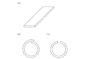
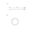
- the sheet-like tire constituent member is a flat plate in the unfolded state, but when forming into a tire shape, it is necessary to match the end and end on the forming drum. is there. However, if the ends are overlapped with each other or if a gap is formed, the uniformity is lowered, and the tire performance may be adversely affected (see FIGS. 6B and 6C).
- variable die head is controlled so that the dimension in the width direction of the opening of the die head is gradually changed. Moreover, in order to form a tread portion having a relatively large thickness, the tread portion is formed by overlapping a plurality of thin rubber layers.
- variable die head disclosed in the above-mentioned Patent Document 1 has a problem that not only the mold configuration is complicated, but also it takes a long time to form a plurality of thin rubber layers.
- the present invention has been made in view of the above circumstances, and an object thereof is to provide a sheet-like rubber molding apparatus and method capable of shortening molding time without complicating the mold configuration. .
- a sheet-like rubber molding apparatus for extruding a sheet-like rubber from a die head of an extruder and molding a tire constituent member having a predetermined width and height,
- a die body comprising the die head and having an opening having a predetermined cross-sectional shape;
- a variable die lip disposed on the front side of the die body and capable of changing the height of the opening;
- a die lip control unit for controlling the operation of the variable die lip,
- the variable die lip is composed of a first movable body located on one side in the height direction and a second movable body located on the other side in the height direction,
- the die lip control unit gradually drives the first movable body in the opening direction from the state where the first movable body and the second movable body are closed at the start of molding, and after reaching a predetermined height, the first movable body
- the variable die lip is controlled so that the position of the body and the second movable body is maintained, and the second movable body
- the die head is composed of an upstream die body and a downstream variable die lip.
- the die body is fixed and has an opening having a predetermined cross-sectional shape.
- the variable die lip includes a first movable body and a second movable body.
- the first movable body and the second movable body are in positions where the openings are closed.
- the height dimension of the extruded rubber member gradually increases from zero.
- the first movable body When the first movable body reaches a predetermined height, the first movable body and the second movable body hold their positions for a while after that. Thereby, a rubber member having a constant cross-sectional shape is extruded. At the end of molding, the second movable body is driven to gradually move in the closing direction. Thereby, the height dimension of the rubber member to be extrusion-molded gradually goes to zero.
- the variable die lip By controlling the variable die lip in this way, a tire constituent member having a shape as shown in FIG. 7B is formed.
- the configuration of the variable die lip has only two movable bodies and suppresses the complication of the configuration.
- the molding time can be shortened instead of stacking thin rubber members in layers. As described above, it is possible to provide a sheet-like rubber molding apparatus capable of reducing the molding time without complicating the mold configuration.
- the gear pump control unit preferably controls the gear pump to control the amount of rubber discharged from the die body.
- a fixed amount of rubber can be supplied to the die head by providing a gear pump. Further, since the cross-sectional shape of the extruded rubber changes at the start of molding and at the end of molding, it is necessary to supply the rubber accordingly. Therefore, by controlling the rotational speed of the gear pump and the like, the rubber can be supplied to the die head in accordance with the cross-sectional shape of the extruded rubber.
- a sheet-like rubber molding method uses a sheet-like rubber molding apparatus having the above-described characteristic configuration to extrude a sheet-like rubber from a die head of an extruder, and has a predetermined width and height.
- a sheet-like rubber molding method for molding a tire constituent member comprising: a first movable body gradually opening from a state in which the first movable body and the second movable body are closed at the start of molding of the tire constituent member Driving to Holding the position of the first movable body and the second movable body after the first movable body reaches a predetermined height; And a step of gradually driving the second movable body in the closing direction at the end of molding.
- the step of controlling the driving of the gear pump arranged on the upstream side of the die head further includes the step of controlling the gear pump to control the amount of rubber discharged from the variable die lip at the start of molding and at the end of molding when the variable die lip is controlled.
- the rubber can be supplied to the die head in accordance with the cross-sectional shape of the extruded rubber.
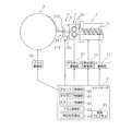
- FIG. 1 is a schematic diagram showing the configuration of a sheet-like rubber molding apparatus.
- a sheet-like rubber molding apparatus A includes an extruder 1, a gear pump 2 provided on the downstream side of the extruder 1, a die head 3 provided on the downstream side of the gear pump 2, and a later-described die head 3. And a movable body drive unit 4 for driving the variable die lip 31. Moreover, the shaping
- the extruder 1 includes a screw 10 for kneading rubber introduced from a hopper (not shown) and a screw driving unit 11 for rotationally driving the screw 10.
- the rubber kneaded by the screw 10 is fed into the gear pump 2.
- the gear pump 2 includes a pair of gears 20 and is driven by a gear pump driving unit 21.
- the gear pump 2 has a function of supplying a fixed amount of rubber to the die head 3 on the downstream side, whereby stable rubber can be supplied. The supply amount can be performed by controlling the rotation speed of the gear pump 2.
- the die head 3 includes a die body 30 and a variable die lip 31.
- the die body 30 is provided with a rubber passage inside, and an opening having a predetermined cross-sectional shape is formed.
- a trapezoidal opening 32 is formed.
- the shape of the opening 32 corresponds to the shape of the tire constituent member to be molded. In the present embodiment, an example in which a sheet-like tread portion is molded will be described.
- a variable die lip 31 is provided on the front side (downstream side) of the die body 30 and includes a first movable body 310 and a second movable body 311.
- the first and second movable bodies 310 and 311 are driven by the movable body driving unit 4. Details of the variable die lip 31 and the movable body drive unit 4 will be described later.
- the rubber extruded from the die head 3 is attached to the outer surface of the molding drum 5.
- the forming drum 5 is a rotating body having a cylindrical shape, and is driven by a drum driving unit 50.
- the controller 6 has a function of controlling the operation of each part of the sheet rubber molding apparatus A.
- the die lip control unit 60 controls driving of the variable die lip 31.
- the gear pump control unit 61 controls the rotational speed of the gear pump 2.
- the screw control unit 62 performs drive control of the screw 10 of the extruder 1.
- the drum control unit 63 controls the rotation speed and drive timing of the forming drum 5.
- the extruder drive unit 12 is a drive unit for bringing the entire extruder 1, die head 3, and movable body drive unit 4 close to and away from the forming drum 5.
- the extruder control unit 64 controls the extruder 1 and the like so that the distance from the forming drum 5 is appropriate.
- the controller 6 has a computer configuration such as a CPU and a memory, and its control is performed based on a control program 65.
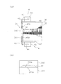
- FIG. 2A is a side sectional view
- FIG. 2B is a front view.
- a flow path 33 through which rubber flows is provided inside the die body 30, and gradually cuts from the upstream side where the gear pump 2 is disposed toward the downstream side where the opening 32 is formed.
- the area is set to be small.
- the variable die lip 31 includes a first movable body 310 and a second movable body 311 and is formed in a thick plate shape.
- the first movable body 310 is driven in the vertical direction of FIG. 2 by the first drive motor 40, the horizontal drive shaft 41, and the vertical drive shaft.
- the horizontal drive shaft 41 and the vertical drive shaft 42 are driven and transmitted by a bevel gear.
- a drive screw 42 is formed below the vertical drive shaft 42, and is screwed into the first movable body 310. Accordingly, the first movable body 310 can be driven in the vertical direction by driving the first drive motor 40 and rotating the vertical drive shaft 42.
- the second movable body 311 is also driven in the vertical direction in FIG. 2 by the second drive motor 43, the horizontal drive shaft 44, and the vertical drive shaft 45, similarly to the first movable body 310.
- a drive screw 45 a is formed on the top of the vertical drive shaft 45, and is screwed into the second movable body 311. Therefore, the second movable body 311 can be driven in the vertical direction by driving the second drive motor 43 and rotating the vertical drive shaft 45.
- the first drive motor 40 is mounted on a support base 46, and the support base 46 is attached to the upper surface of the die body 30.
- the second drive motor 43 is mounted on a support base 47, and the support base 47 is attached to the lower surface of the die body 30.
- These support bases 46 and 47 also have a bearing function for the vertical drive shafts 42 and 45.
- the opening 32 is trapezoidal when viewed from the front, and the lower side is longer than the upper side.
- the lower end portion 310a of the first movable body 310 and the upper end portion 311a of the second movable body 311 are in contact before the start of molding, and thus the opening 32 is in a completely closed state.
- the opening 32 is exposed, and rubber corresponding to the exposed area is extruded.
- the first and second movable bodies 310 and 311 are driven only in the vertical direction, and are not driven in the width direction (the horizontal direction in FIG. 2).
- variable die lip 31 is set to the initial state shown in FIG. That is, the first movable body 310 and the second movable body 311 are in contact with each other, and the opening 32 of the die head 3 is closed (S1).
- the first drive motor 40 is controlled by the die head controller 60 of the controller 6 to start driving the first movable body 310 upward (S2, FIG. 4A).
- the second movable body 311 is in a fixed state. Thereby, the opening part 32 is gradually exposed and rubber is extruded. The cross-sectional shape of the rubber gradually increases (FIG. 4B).
- FIG. 4C shows a state where the first movable body 310 is driven at a predetermined height (S3). At this time, the opening 32 is almost exposed.
- the stage in which the first movable body 310 moves to a predetermined height is defined as the molding start time, and is indicated by P1 in FIG.
- the first movable body 310 After the first movable body 310 is driven to a predetermined height, the first movable body 310 is held at that position (S4). Further, the second movable body 311 is still in the initial position. Therefore, after this, a rubber having a constant cross-sectional shape is extruded. Specifically, the rubber having the shape of the opening 32 is extruded. This state is defined as a steady state, and is indicated by P2 in FIG.
- the second drive motor 43 is controlled by the die lip control unit 60 to start driving the second movable body 311 upward (S5, FIG. 4D).
- the first movable body 310 remains stopped above. Thereby, the opening part 32 closes gradually (FIG. 4E).
- FIG. 5 shows the tire constituent member G in a state of being attached to the outer surface of the forming drum 5.
- a joint portion between the end portions of the tire constituent member G is indicated by G1.
- the tire constituent member G having a uniform thickness as a whole can be obtained by superimposing them.
- the control of the gear pump 2 at the start of molding and at the end of molding will be described.
- the cross-sectional shape of the extruded rubber gradually changes. Therefore, it is preferable that the amount of rubber supplied from the gear pump 2 to the die head 3 is also changed in conjunction with the change in the cross-sectional shape. Therefore, at the start of molding, control is performed so that the rotational speed of the gear pump 2 gradually increases. At regular times, the rotation of the gear pump 2 is maintained at a constant speed. At the end of molding, control is performed so that the rotational speed of the gear pump 2 gradually decreases.
- the joining portion can be joined to have a uniform thickness without a step, and the uniformity can be improved.
- the molding time is shortened and productivity is dramatically improved as compared with the molding method by strip build as described in the prior art.
- the tread portion is exemplified as the tire constituent member, but the present invention can also be applied to the case where a tire constituent member other than the tread portion is molded. Moreover, various modifications can be considered for the cross-sectional shape of the tire constituent member, and the tire shape member is not limited to a specific shape.
- the configuration in which the opening 32 is closed by the first movable body 310 as illustrated in FIG. 2 has been described, but a configuration in which the opening 32 is closed by the second movable body 311 may be employed.
- the second movable body 311 is driven downward to open the opening 32, and at the end of molding, the first movable body 310 is driven downward to close the opening 32. become. Therefore, the moving direction of the first and second movable bodies 310 and 311 when opening and closing the opening 32 is not limited to a specific direction.
- the speed at which the opening 32 is opened and closed can be set as appropriate.
- various modifications of the specific configuration of the movable body driving unit 4 are possible.
- a sheet-like rubber molding apparatus G tire component G1 joint 1 extruder 2 gear pump 3 die head 4 movable body drive 5 molding drum 6 controller 10 screw 20 gear 30 die body 31 die lip 32 opening 60 die lip controller 61 gear pump controller 62 Screw control unit 63 Drum control unit 64 Extruder control unit 310 First movable body 310a Lower end 311 Second movable body 311a Upper end
Landscapes
- Engineering & Computer Science (AREA)
- Mechanical Engineering (AREA)
- Manufacturing & Machinery (AREA)
- Extrusion Moulding Of Plastics Or The Like (AREA)
- Tyre Moulding (AREA)
Abstract
本発明は、金型構成を複雑化させることなく、かつ、成形時間も短縮化可能なシート状ゴム成形装置及び方法を提供する。本発明のシート状ゴム成形装置は、ダイヘッド3からシート状のゴムを押し出して、所定の幅および高さを有するタイヤ構成部材を成形するシート状ゴム成形装置Aであって、所定断面形状の開口部32を有するダイボディ30と、ダイボディ30の前方側に配置され、開口部32の高さ寸法を変更可能な可変ダイリップ31と、を備え、可変ダイリップ31は、高さ方向の一方に位置する第1可動体310と、他方に位置する第2可動体311とにより構成され、ダイヘッド制御部60は、成形開始時に第1・第2可動体310,311を閉じた状態から、第1可動体310を開方向へ駆動し、所定の高さに到達した後、第1・第2可動体310,311の位置を保持し、成形終了時に第2可動体311を閉方向へ駆動するように、可変ダイリップ31を制御する。
Description
本発明は、押出機のダイヘッドからシート状のゴムを押し出して、所定の幅および高さを有するタイヤ構成部材を成形するシート状ゴム成形装置及び方法に関するものである。
かかるシート状のタイヤ構成部材の一例としてトレッドゴムがある。シート状のタイヤ構成部材は、図6(a)に示すように、展開した状態では平板状であるが、タイヤ形状に成形するときは、成形ドラムの上で端部と端部を合わせる必要がある。しかし、端部同士を合わせるときに、重なりが生じたり、隙間が生じると、ユニフォミティが低下し、タイヤ性能に悪影響を及ぼす恐れがある(図6(b)(c)参照)。
そこで、図7(a)に示すように、シート状のタイヤ構成部材の前後の端部を厚みが徐々に変化するように形成する必要がある。これにより、図7(b)に示すように、端部同士を全体の厚みが均一になるように重ね合わせることができる。このような形状を有するゴムの成形を実現するために、下記特許文献1に開示される可変ダイヘッドによるゴム層成形方法が知られている。
具体的には、特許文献1の図6に開示されている。ダイヘッドの開口部の幅方向の寸法を徐々に変えていくように、可変ダイヘッドが制御される。また、厚みが比較的厚いトレッド部を形成するため、厚さの薄いゴムを何層も重ね合わせることで、トレッド部を形成している。
しかしながら、上記特許文献1に開示される可変ダイヘッドは金型構成が複雑化するだけでなく、厚さの薄いゴムを何層も重ねて成形するので成形時間がかかるという問題がある。
本発明は上記実情に鑑みてなされたものであり、その課題は、金型構成を複雑化させることなく、かつ、成形時間も短縮化可能なシート状ゴム成形装置及び方法を提供することである。
上記課題を解決するため本発明に係るシート状ゴム成形装置は、
押出機のダイヘッドからシート状のゴムを押し出して、所定の幅および高さを有するタイヤ構成部材を成形するシート状ゴム成形装置であって、
前記ダイヘッドを構成し、所定断面形状の開口部を有するダイボディと、
このダイボディの前方側に配置され、前記開口部の前記高さ寸法を変更可能な可変ダイリップと、
前記可変ダイリップの動作を制御するダイリップ制御部と、を備え、
前記可変ダイリップは、高さ方向の一方に位置する第1可動体と、高さ方向の他方に位置する第2可動体とにより構成され、
前記ダイリップ制御部は、成形開始時に前記第1可動体と第2可動体を閉じた状態から、第1可動体を徐々に開方向へ駆動し、所定の高さに到達した後、第1可動体と第2可動体の位置を保持し、成形終了時に第2可動体を徐々に閉方向へ駆動するように、前記可変ダイリップを制御することを特徴とするものである。
押出機のダイヘッドからシート状のゴムを押し出して、所定の幅および高さを有するタイヤ構成部材を成形するシート状ゴム成形装置であって、
前記ダイヘッドを構成し、所定断面形状の開口部を有するダイボディと、
このダイボディの前方側に配置され、前記開口部の前記高さ寸法を変更可能な可変ダイリップと、
前記可変ダイリップの動作を制御するダイリップ制御部と、を備え、
前記可変ダイリップは、高さ方向の一方に位置する第1可動体と、高さ方向の他方に位置する第2可動体とにより構成され、
前記ダイリップ制御部は、成形開始時に前記第1可動体と第2可動体を閉じた状態から、第1可動体を徐々に開方向へ駆動し、所定の高さに到達した後、第1可動体と第2可動体の位置を保持し、成形終了時に第2可動体を徐々に閉方向へ駆動するように、前記可変ダイリップを制御することを特徴とするものである。
かかる構成によるシート状ゴム成形装置の作用・効果を説明する。まず、ダイヘッドは上流側のダイボディと下流側の可変ダイリップにより構成される。ダイボディは固定であり、所定断面形状の開口部を有する。この開口部の高さ寸法を可変にするため、可変ダイリップは、第1可動体と第2可動体を備えている。成形開始時は、第1可動体と第2可動体は、開口部を閉じた位置にある。ついで、第1可動体を徐々に開方向へと駆動することで、押し出し成形されるゴム部材の高さ寸法が0から徐々に増加していく。第1可動体が所定の高さに到達すると、第1可動体と第2可動体は、その位置をその後しばらく保持する。これにより、一定の断面形状のゴム部材が押し出し成形される。そして、成形終了時には、第2可動体のほうを駆動して、徐々に閉方向へと移動させる。これにより、押し出し成形されるゴム部材の高さ寸法が徐々に0へと向かう。このように可変ダイリップを制御することで、図7(b)に示すような形状のタイヤ構成部材が成形される。可変ダイリップの構成は、2つの可動体を有するだけであり、構成が複雑化することを抑制している。また、厚さの薄いゴム部材を層状に重ねるのではなく、成形時間も短縮化することができる。以上のように、金型構成を複雑化させることなく、かつ、成形時間も短縮化可能なシート状ゴム成形装置を提供することができる。
本発明において、前記ダイヘッドの上流側に配置されるギアポンプと、このギアポンプの駆動を制御するギアポンプ制御部と、を備え、
前記ダイリップ制御部により、前記可変ダイリップの制御が行われているとき、前記ギアポンプ制御部は、前記ギアポンプを制御して、前記ダイボディからのゴム吐出量を制御することが好ましい。
前記ダイリップ制御部により、前記可変ダイリップの制御が行われているとき、前記ギアポンプ制御部は、前記ギアポンプを制御して、前記ダイボディからのゴム吐出量を制御することが好ましい。
ギアポンプを設けることで、ダイヘッドへ向けて定量のゴムを供給することができる。また、成形開始時と成形終了時では、押し出し成形されるゴムの断面形状が変化するため、それに合わせてゴムの供給を行う必要がある。そこで、ギアポンプの回転数等を制御することで、押し出し成形されるゴムの断面形状に合わせて、ダイヘッドへのゴムの供給を行うことができる。
上記課題を解決するため本発明に係るシート状ゴム成形方法は、上記特徴構成を有するシート状ゴム成形装置を用いて、押出機のダイヘッドからシート状のゴムを押し出して、所定の幅および高さを有するタイヤ構成部材を成形するシート状ゴム成形方法であって、前記タイヤ構成部材の成形開始時に前記第1可動体と第2可動体を閉じた状態から、第1可動体を徐々に開方向へ駆動するステップと、
前記第1可動体が所定の高さに到達した後、第1可動体と第2可動体の位置を保持するステップと、
成形終了時に前記第2可動体を徐々に閉方向へ駆動するステップと、を有することを特徴とするものである。
前記第1可動体が所定の高さに到達した後、第1可動体と第2可動体の位置を保持するステップと、
成形終了時に前記第2可動体を徐々に閉方向へ駆動するステップと、を有することを特徴とするものである。
かかる構成によるシート状ゴム成形方法の作用・効果は、すでに述べたとおりである。すなわち、金型構成を複雑化させることなく、かつ、成形時間も短縮化可能になる。
本発明において、前記ダイヘッドの上流側に配置されるギアポンプの駆動を制御するステップと、
前記可変ダイリップの制御が行われる前記成形開始時と前記成形終了時に、前記ギアポンプを制御して、前記可変ダイリップからのゴム吐出量を制御するステップと、を更に有することが好ましい。
前記可変ダイリップの制御が行われる前記成形開始時と前記成形終了時に、前記ギアポンプを制御して、前記可変ダイリップからのゴム吐出量を制御するステップと、を更に有することが好ましい。
かかる構成により、すでに述べたとおり、押し出し成形されるゴムの断面形状に合わせて、ダイヘッドへのゴムの供給を行うことができる。
本発明に係る前記タイヤ構成部材を成形ドラムに直接貼り付けるステップを有することが好ましい。これにより、成形工程を短縮化し、効率よくタイヤ構成部材を成形することができる。
本発明に係るシート状ゴム成形装置及び方法の好適な実施形態を図面を用いて説明する。図1は、シート状ゴム成形装置の構成を示す概略図である。
<シート状ゴム成形装置の構成>
図1において、シート状ゴム成形装置Aは、押出機1と、押出機1の下流側に設けられたギアポンプ2と、ギアポンプ2の下流側に設けられたダイヘッド3と、ダイヘッド3を構成する後述の可変ダイリップ31を駆動する可動体駆動部4とを備える。また、タイヤを構成するタイヤ構成部材を巻き付けるための成形ドラム5が設けられる。
図1において、シート状ゴム成形装置Aは、押出機1と、押出機1の下流側に設けられたギアポンプ2と、ギアポンプ2の下流側に設けられたダイヘッド3と、ダイヘッド3を構成する後述の可変ダイリップ31を駆動する可動体駆動部4とを備える。また、タイヤを構成するタイヤ構成部材を巻き付けるための成形ドラム5が設けられる。
押出機1は、不図示のホッパーから投入されたゴムを混錬するためのスクリュー10と、このスクリュー10を回転駆動するためのスクリュー駆動部11を備えている。スクリュー10により混錬されたゴムは、ギアポンプ2へと送り込まれる。ギアポンプ2は、一対のギヤ20により構成され、ギアポンプ駆動部21により駆動される。ギアポンプ2は、定量のゴムを下流側のダイヘッド3へ供給する機能を有し、これにより、安定したゴムの供給を行うことができる。供給量は、ギアポンプ2の回転速度を制御することで行うことができる。
ダイヘッド3は、ダイボディ30と、可変ダイリップ31により構成される。ダイボディ30は、内部にゴムの通路が設けられており、所定の断面形状を有する開口部が形成される。ダイボディ30を正面側(ゴムが吐出する側)から見ると、台形の開口部32が形成されている。この開口部32の形状は、成形するタイヤ構成部材の形状に対応しており、本実施形態では、シート状のトレッド部を成形する例を説明する。
ダイボディ30の前方側(下流側)には、可変ダイリップ31が設けられており、第1可動体310と第2可動体311を備えている。これら第1・第2可動体310,311は、可動体駆動部4により駆動される。これら可変ダイリップ31と、可動体駆動部4の詳細については、後述する。
ダイヘッド3から押し出し成形されたゴムは、成形ドラム5の外表面に貼り付けられる。成形ドラム5は、円筒形を有する回転体であり、ドラム駆動部50により駆動される。
コントローラ6は、シート状ゴム成形装置Aの各部の動作を制御する機能を有する。ダイリップ制御部60は、可変ダイリップ31の駆動を制御する。ギアポンプ制御部61は、ギアポンプ2の回転速度を制御する。スクリュー制御部62は、押出機1のスクリュー10の駆動制御を行う。ドラム制御部63は、成形ドラム5の回転速度や駆動タイミング等を制御する。押出機駆動部12は、押出機1、ダイヘッド3、可動体駆動部4の全体を、成形ドラム5に対して近接・離間させるための駆動部である。押出機制御部64は、上記押出機1等を制御して、成形ドラム5との間隔が適切になるように制御する。コントローラ6は、CPU、メモリ等のコンピュータの構成を備えており、その制御は、制御プログラム65に基づいて行われる。
<ダイヘッドの構成>
次に、図2によりダイヘッド3の詳細な構成について説明する。図2(a)は側断面図であり、図2(b)は、正面図である。図2に示すように、ダイボディ30の内部にはゴムが流れる流路33が設けられており、ギアポンプ2が配置される上流側から開口部32が形成される下流側へ向けて、徐々に断面積が小さくなるように設定されている。
次に、図2によりダイヘッド3の詳細な構成について説明する。図2(a)は側断面図であり、図2(b)は、正面図である。図2に示すように、ダイボディ30の内部にはゴムが流れる流路33が設けられており、ギアポンプ2が配置される上流側から開口部32が形成される下流側へ向けて、徐々に断面積が小さくなるように設定されている。
可変ダイリップ31は、第1可動体310と第2可動体311を備えており、厚みが厚いプレート状に形成される。第1可動体310は、第1駆動モータ40と、水平駆動軸41、垂直駆動軸42により図2の上下方向に駆動される。水平駆動軸41と垂直駆動軸42とは、傘歯車により駆動伝達される。垂直駆動軸42の下部には駆動ネジ42が形成されており、これが第1可動体310に螺合している。従って、第1駆動モータ40を駆動し、垂直駆動軸42を回転させることで、第1可動体310を上下方向に駆動させることができる。
第2可動体311も、第1可動体310と同様に、第2駆動モータ43、水平駆動軸44、垂直駆動軸45により図2の上下方向に駆動される。垂直駆動軸45の上部には駆動ネジ45aが形成されており、これが第2可動体311に螺合している。従って、第2駆動モータ43を駆動し、垂直駆動軸45を回転させることで、第2可動体311を上下方向に駆動させることができる。
第1駆動モータ40は、支持台46の上に搭載され、この支持台46は、ダイボディ30の上面に取り付けられている。第2駆動モータ43は、支持台47の上に搭載され、この支持台47は、ダイボディ30の下面に取り付けられている。これら支持台46,47は、垂直駆動軸42,45の軸受機能も備えている。
図2(b)に示すように、開口部32は正面から見ると台形であり、上辺よりも下辺のほうが長さが長い。第1可動体310の下端部310aと第2可動体311の上端部311aは、成形開始前は当接しており、従って、開口部32は完全に閉鎖された状態である。この第1・第2可動体310,311を上下方向に駆動することで、開口部32が露出し、その露出した面積に対応したゴムが押し出し成形される。第1・第2可動体310,311は、上下方向にのみ駆動され、幅方向(図2の左右方向)には駆動されない。
<タイヤ構成部材の成形工程>
次に、タイヤ構成部材であるトレッドゴムの成形工程を説明する。図3のフローチャートと、図4A~4Fにより説明する。
次に、タイヤ構成部材であるトレッドゴムの成形工程を説明する。図3のフローチャートと、図4A~4Fにより説明する。
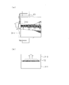
まず、可変ダイリップ31は図2に示す初期状態に設定されている。すなわち、第1可動体310と第2可動体311は、互いに当接しており、ダイヘッド3の開口部32は閉鎖されている(S1)。次に、コントローラ6のダイヘッド制御部60により、第1駆動モータ40を制御し、第1可動体310を上方に駆動開始する(S2、図4A)。第2可動体311は固定された状態である。これにより、徐々に開口部32が露出していき、ゴムが押し出し成形されていく。ゴムの断面形状は徐々に大きくなっていく(図4B)。
第1可動体310が所定の高さはで駆動された状態を図4Cに示す(S3)。このとき、開口部32は、ほぼ露出された状態になる。この第1可動体310が所定高さまで移動する段階を成形開始時と定義し、図7にP1で示す。
第1可動体310が所定高さまで駆動された後、第1可動体310はその位置で保持される(S4)。また、第2可動体311は、依然として初期位置のままである。従って、この後は、一定の断面形状のゴムが押し出し成形される。具体的には、開口部32の形状のゴムが押し出し成形される。この状態を定常時と定義し、図7にはP2で示す。
次に、成形終了時に向かうときは、ダイリップ制御部60により、第2駆動モータ43を制御し、第2可動体311を上方に駆動開始する(S5、図4D)。第1可動体310は、上方で停止したままである。これにより、徐々に開口部32が閉鎖していく(図4E)。
そして、第2可動体311が上昇して、第1可動体310の下端部310aと、第2可動体311の上端部311aが当接した時点でゴムの吐出が終了する(S6)。この第2可動体311が上昇して停止するまでの区間を成形終了時として定義し、図7にP3で示す。このとき、図4Fに示すように、開口部32は完全に閉鎖した状態になる。
図4Fの状態では、第1可動体310も第2可動体311も上方へ移動した状態なので、次のタイヤ構成部材の成形を開始するまでに、図2に示す、初期位置に復帰させる(S7)。すなわち、第1駆動モータ40と第2駆動モータ43の双方を駆動して、第1・2可動体310,311を下方へ駆動する。
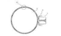
図5は、成形ドラム5の外表面に貼り付けられた状態のタイヤ構成部材Gを示す。タイヤ構成部材Gの端部同士の接合部がG1で示される。本発明による成形方法によれば、端部のゴムの厚みが徐々に薄くなっているので、それらを重ね合わせれば、全体として均一な厚みのタイヤ構成部材Gが得られる。
次に、図4で説明した成形工程において、ダイヘッド3と成形ドラム5の相対位置関係を説明する。成形開始時と成形終了時は、できるだけダイヘッド3が成形ドラム5に近接するように制御する。そして、成形開始時から定常時に向けて、徐々に成形ドラム5とダイヘッド3の距離が開いていくように制御する。また、定常時には、成形ドラム5とダイヘッド3の間隔は一定に保持する。そして、成形終了時に向けて、再び、ダイヘッド3が成形ドラム5に近接していくように制御する。図5は、近接した状態が示されている。
次に、成形開始時と成形終了時におけるギアポンプ2の制御について説明する。成形開始時と成形終了時は、押し出し成形されるゴムの断面形状が徐々に変化する。従って、ギアポンプ2からダイヘッド3へと供給するゴム量も、この断面形状の変化に連動して変化させることが好ましい。そこで、成形開始時は、徐々にギアポンプ2の回転速度が増加するように制御する。定常時は、ギアポンプ2の回転は一定速度に保持される。そして、成形終了時は、徐々にギアポンプ2の回転速度が減少するように制御する。このようにギアポンプ2の制御と連動させることで、適切な量のゴムをダイヘッド3の方へ供給することができ、押し出し成形されるゴムの形状も精度よく成形することができる。
本発明により成形されたタイヤ構成部材を用いることで、接合部に段差が生じることなく、均一な厚みになるように接合でき、ユニフォミティが向上する。また、従来技術で説明したようなストリップビルドによる成形方法に比べると、成形時間が短縮化され、生産性が飛躍的に向上する。
<別実施形態>
本実施形態において、ギアポンプを用いる構成を説明したが、ギアポンプがない場合でも、本発明は応用することができる。
本実施形態において、ギアポンプを用いる構成を説明したが、ギアポンプがない場合でも、本発明は応用することができる。
本実施形態において、タイヤ構成部材としてトレッド部を例示したが、トレッド部以外のタイヤ構成部材を成形する場合にも、本発明を応用することができる。また、タイヤ構成部材の断面形状についても、種々の変形例が考えられ、特定の形状に限定されるものではない。
可変ダイリップ31の駆動機構については種々の変形例が可能である。本実施形態では、図2に示すように第1可動体310により開口部32を閉鎖する構成を説明したが、第2可動体311により開口部32を閉鎖する構成を採用してもよい。この場合は、成形開始時において、第2可動体311が下方に駆動されて開口部32を開いていき、成形終了時には、第1可動体310が下方に駆動されて開口部32を閉鎖する形になる。従って、開口部32を開閉するときの第1・第2可動体310,311の移動方向は、特定の方向に限定されるものではない。開口部32を開閉していくときの速度は、適宜設定することができる。その他、可動体駆動部4の具体的な構成については、種々の変形例が可能である。
A シート状ゴム成形装置
G タイヤ構成部材
G1 接合部
1 押出機
2 ギアポンプ
3 ダイヘッド
4 可動体駆動部
5 成形ドラム
6 コントローラ
10 スクリュー
20 ギヤ
30 ダイボディ
31 ダイリップ
32 開口部
60 ダイリップ制御部
61 ギアポンプ制御部
62 スクリュー制御部
63 ドラム制御部
64 押出機制御部
310 第1可動体
310a 下端部
311 第2可動体
311a 上端部
G タイヤ構成部材
G1 接合部
1 押出機
2 ギアポンプ
3 ダイヘッド
4 可動体駆動部
5 成形ドラム
6 コントローラ
10 スクリュー
20 ギヤ
30 ダイボディ
31 ダイリップ
32 開口部
60 ダイリップ制御部
61 ギアポンプ制御部
62 スクリュー制御部
63 ドラム制御部
64 押出機制御部
310 第1可動体
310a 下端部
311 第2可動体
311a 上端部
Claims (5)
- 押出機のダイヘッドからシート状のゴムを押し出して、所定の幅および高さを有するタイヤ構成部材を成形するシート状ゴム成形装置であって、
前記ダイヘッドを構成し、所定断面形状の開口部を有するダイボディと、
このダイボディの前方側に配置され、前記開口部の前記高さ寸法を変更可能な可変ダイリップと、
前記可変ダイリップの動作を制御するダイリップ制御部と、を備え、
前記可変ダイリップは、高さ方向の一方に位置する第1可動体と、高さ方向の他方に位置する第2可動体とにより構成され、
前記ダイリップ制御部は、成形開始時に前記第1可動体と第2可動体を閉じた状態から、第1可動体を徐々に開方向へ駆動し、所定の高さに到達した後、第1可動体と第2可動体の位置を保持し、成形終了時に第2可動体を徐々に閉方向へ駆動するように、前記可変ダイリップを制御することを特徴とするシート状ゴム成形装置。 - 前記ダイヘッドの上流側に配置されるギアポンプと、
このギアポンプの駆動を制御するギアポンプ制御部と、を備え、
前記ダイリップ制御部により、前記可変ダイリップの制御が行われているとき、前記ギアポンプ制御部は、前記ギアポンプを制御して、前記固定ダイヘッド部分からのゴム吐出量を制御することを特徴とする請求項1に記載のシート状ゴム成形装置。 - 請求項1又は2に記載のシート状ゴム成形装置を用いて、押出機のダイヘッドからシート状のゴムを押し出して、所定の幅および高さを有するタイヤ構成部材を成形するシート状ゴム成形方法であって、
前記タイヤ構成部材の成形開始時に前記第1可動体と第2可動体を閉じた状態から、第1可動体を徐々に開方向へ駆動するステップと、
前記第1可動体が所定の高さに到達した後、第1可動体と第2可動体の位置を保持するステップと、
成形終了時に前記第2可動体を徐々に閉方向へ駆動するステップと、を有することを特徴とするシート状ゴム成形方法。 - 前記ダイヘッドの上流側に配置されるギアポンプの駆動を制御するステップと、
前記可変ダイリップの制御が行われる前記成形開始時と前記成形終了時に、前記ギアポンプを制御して、前記可変ダイリップからのゴム吐出量を制御するステップと、を更に有することを特徴とする請求項3に記載のシート状ゴム成形装置。 - 前記タイヤ構成部材を成形ドラムに直接貼り付けるステップを有することを特徴とする請求項3又は4に記載のシート状ゴム成形装置。
Priority Applications (3)
| Application Number | Priority Date | Filing Date | Title |
|---|---|---|---|
| CN201280011907.7A CN103582553B (zh) | 2011-03-08 | 2012-03-02 | 片状橡胶成型装置及方法 |
| US14/001,973 US9751269B2 (en) | 2011-03-08 | 2012-03-02 | Device and method for forming sheet-like rubber |
| US15/661,647 US10265917B2 (en) | 2011-03-08 | 2017-07-27 | Device and method for forming sheet-like rubber |
Applications Claiming Priority (2)
| Application Number | Priority Date | Filing Date | Title |
|---|---|---|---|
| JP2011-050442 | 2011-03-08 | ||
| JP2011050442A JP5651504B2 (ja) | 2011-03-08 | 2011-03-08 | シート状ゴム成形装置及び方法 |
Related Child Applications (2)
| Application Number | Title | Priority Date | Filing Date |
|---|---|---|---|
| US14/001,973 A-371-Of-International US9751269B2 (en) | 2011-03-08 | 2012-03-02 | Device and method for forming sheet-like rubber |
| US15/661,647 Division US10265917B2 (en) | 2011-03-08 | 2017-07-27 | Device and method for forming sheet-like rubber |
Publications (1)
| Publication Number | Publication Date |
|---|---|
| WO2012121148A1 true WO2012121148A1 (ja) | 2012-09-13 |
Family
ID=46798112
Family Applications (1)
| Application Number | Title | Priority Date | Filing Date |
|---|---|---|---|
| PCT/JP2012/055395 Ceased WO2012121148A1 (ja) | 2011-03-08 | 2012-03-02 | シート状ゴム成形装置及び方法 |
Country Status (4)
| Country | Link |
|---|---|
| US (2) | US9751269B2 (ja) |
| JP (1) | JP5651504B2 (ja) |
| CN (1) | CN103582553B (ja) |
| WO (1) | WO2012121148A1 (ja) |
Cited By (2)
| Publication number | Priority date | Publication date | Assignee | Title |
|---|---|---|---|---|
| US10821644B2 (en) | 2017-02-16 | 2020-11-03 | The Yokohama Rubber Co., Ltd. | Rubber extrusion device and method for manufacturing rubber extrudate |
| US11534950B2 (en) | 2017-08-21 | 2022-12-27 | The Yokohama Rubber Co., Ltd. | Rubber extrusion device and method for manufacturing rubber extrudate |
Families Citing this family (18)
| Publication number | Priority date | Publication date | Assignee | Title |
|---|---|---|---|---|
| JP6105330B2 (ja) * | 2013-03-07 | 2017-03-29 | 東洋ゴム工業株式会社 | ゴム部材成型装置 |
| JP6147613B2 (ja) * | 2013-09-02 | 2017-06-14 | 東洋ゴム工業株式会社 | ゴム成形装置 |
| JP6232269B2 (ja) * | 2013-12-03 | 2017-11-15 | 東洋ゴム工業株式会社 | シート状ゴム成形装置及びシート状ゴム成形用口金 |
| JP6511295B2 (ja) * | 2015-03-05 | 2019-05-15 | Toyo Tire株式会社 | ゴム部材の成形方法及び成形装置 |
| US11685095B2 (en) | 2015-06-30 | 2023-06-27 | The Goodyear Tire & Rubber Company | Method and apparatus for forming tire components using a coextruded strip |
| US10195779B2 (en) | 2015-07-29 | 2019-02-05 | The Boeing Company | Systems and methods for making composite structures |
| JP6520967B2 (ja) * | 2017-02-16 | 2019-05-29 | 横浜ゴム株式会社 | ゴム押出装置およびゴム押出物の製造方法 |
| JP6520968B2 (ja) | 2017-02-16 | 2019-05-29 | 横浜ゴム株式会社 | ゴム押出装置およびゴム押出物の製造方法 |
| JP6706215B2 (ja) * | 2017-03-24 | 2020-06-03 | 中田エンヂニアリング株式会社 | ビードエーペックスゴム形成装置 |
| FR3080063B1 (fr) * | 2018-04-17 | 2020-08-28 | Continental Reifen Deutschland Gmbh | Procede de recherche par similitude d’un profil geometrique de pneumatique ou d’un semi-produit de pneumatique |
| US10532512B2 (en) * | 2018-06-07 | 2020-01-14 | Thermwood Corporation | Additive manufacturing apparatus |
| JP7107122B2 (ja) * | 2018-09-18 | 2022-07-27 | 横浜ゴム株式会社 | ゴム材料の押出方法およびシステム |
| JP7107127B2 (ja) * | 2018-09-20 | 2022-07-27 | 横浜ゴム株式会社 | ゴム押出方法および装置 |
| JP7198151B2 (ja) * | 2019-05-17 | 2022-12-28 | Toyo Tire株式会社 | 帯状ゴム部材の成形方法及び成形装置 |
| KR102370656B1 (ko) * | 2020-10-19 | 2022-03-07 | 넥센타이어 주식회사 | 타이어 반제품 제조를 위한 가변형 압출 금형 |
| FR3117919B1 (fr) * | 2020-12-23 | 2022-12-02 | Michelin & Cie | Procédé de fermeture en deux temps d’une installation d’extrusion a rouleau permettant un ajustement précis de l’entrefer de génération d’un profilé |
| JP7719353B2 (ja) * | 2021-05-21 | 2025-08-06 | キョーラク株式会社 | 樹脂供給装置、ダイリップ開閉装置 |
| JP7635093B2 (ja) * | 2021-07-27 | 2025-02-25 | Toyo Tire株式会社 | ゴム部材成形方法、ゴム部材成形装置、成形ドラム、及びプログラム |
Citations (3)
| Publication number | Priority date | Publication date | Assignee | Title |
|---|---|---|---|---|
| JPH0952272A (ja) * | 1995-08-11 | 1997-02-25 | Bridgestone Corp | 帯状物押出用ゲージ可変ヘッド |
| JP2682872B2 (ja) * | 1988-08-18 | 1997-11-26 | アー‐ツェット ホルメン‐ウント マシーネンボウ ゲーエムベーハー | トレッドストリップを製造するためのインゼクタヘッド |
| JP2003011245A (ja) * | 2001-07-05 | 2003-01-15 | Sumitomo Rubber Ind Ltd | トレッドリングのジョイント量検定方法、及び検定装置 |
Family Cites Families (12)
| Publication number | Priority date | Publication date | Assignee | Title |
|---|---|---|---|---|
| HU163760B (ja) * | 1972-02-11 | 1973-10-27 | ||
| US3947201A (en) * | 1973-12-07 | 1976-03-30 | Usm Corporation | Extruder and roll die apparatus |
| DE3637358C1 (en) * | 1986-11-03 | 1988-03-24 | Hermann Berstoff Maschb Gmbh | Extruder-calender for producing films or sheets from plastic, rubber or similarly behaving materials |
| DE4034268A1 (de) * | 1990-03-28 | 1991-10-02 | Troester Maschf Paul | Vorrichtung zur herstellung von bahnenfoermigen platten und folien aus kautschukmischungen und/oder kunststoffen |
| DE9314733U1 (de) * | 1993-08-05 | 1994-06-30 | A-Z Formen- und Maschinenbau GmbH, 80992 München | Runderneuerungsvorrichtung |
| JPH08141466A (ja) * | 1994-11-28 | 1996-06-04 | Hirano Tecseed Co Ltd | リップコータ型塗工装置 |
| CN2222601Y (zh) * | 1995-01-25 | 1996-03-20 | 吴基祥 | 胎面挤出机头 |
| MXPA02000037A (es) * | 1999-06-21 | 2003-01-28 | E Cell Corp | Membrana de intercambio ionico heterogenea y metodo de manufactura de la misma. |
| JP2004243732A (ja) * | 2003-02-17 | 2004-09-02 | Toyo Tire & Rubber Co Ltd | 可変ダイヘッドによるゴム層成形方法及び可変ダイヘッド |
| JP2004249517A (ja) * | 2003-02-19 | 2004-09-09 | Toyo Tire & Rubber Co Ltd | 薄肉ゴムの押出装置及び押出方法 |
| JP4534225B2 (ja) * | 2004-10-29 | 2010-09-01 | 東洋ゴム工業株式会社 | ゴム部材成形設備及びゴム部材成形方法 |
| CN201296034Y (zh) * | 2008-08-12 | 2009-08-26 | 青岛高校软控股份有限公司 | 橡胶螺杆挤出机机头 |
-
2011
- 2011-03-08 JP JP2011050442A patent/JP5651504B2/ja not_active Expired - Fee Related
-
2012
- 2012-03-02 US US14/001,973 patent/US9751269B2/en not_active Expired - Fee Related
- 2012-03-02 CN CN201280011907.7A patent/CN103582553B/zh not_active Expired - Fee Related
- 2012-03-02 WO PCT/JP2012/055395 patent/WO2012121148A1/ja not_active Ceased
-
2017
- 2017-07-27 US US15/661,647 patent/US10265917B2/en not_active Expired - Fee Related
Patent Citations (3)
| Publication number | Priority date | Publication date | Assignee | Title |
|---|---|---|---|---|
| JP2682872B2 (ja) * | 1988-08-18 | 1997-11-26 | アー‐ツェット ホルメン‐ウント マシーネンボウ ゲーエムベーハー | トレッドストリップを製造するためのインゼクタヘッド |
| JPH0952272A (ja) * | 1995-08-11 | 1997-02-25 | Bridgestone Corp | 帯状物押出用ゲージ可変ヘッド |
| JP2003011245A (ja) * | 2001-07-05 | 2003-01-15 | Sumitomo Rubber Ind Ltd | トレッドリングのジョイント量検定方法、及び検定装置 |
Cited By (2)
| Publication number | Priority date | Publication date | Assignee | Title |
|---|---|---|---|---|
| US10821644B2 (en) | 2017-02-16 | 2020-11-03 | The Yokohama Rubber Co., Ltd. | Rubber extrusion device and method for manufacturing rubber extrudate |
| US11534950B2 (en) | 2017-08-21 | 2022-12-27 | The Yokohama Rubber Co., Ltd. | Rubber extrusion device and method for manufacturing rubber extrudate |
Also Published As
| Publication number | Publication date |
|---|---|
| US10265917B2 (en) | 2019-04-23 |
| CN103582553B (zh) | 2015-12-23 |
| US9751269B2 (en) | 2017-09-05 |
| JP2012187712A (ja) | 2012-10-04 |
| CN103582553A (zh) | 2014-02-12 |
| US20170320282A1 (en) | 2017-11-09 |
| US20130334722A1 (en) | 2013-12-19 |
| JP5651504B2 (ja) | 2015-01-14 |
Similar Documents
| Publication | Publication Date | Title |
|---|---|---|
| JP5651504B2 (ja) | シート状ゴム成形装置及び方法 | |
| JP5313741B2 (ja) | タイヤ成形方法 | |
| US10556394B2 (en) | Apparatus and method for manufacturing rubber member | |
| CN103128944B (zh) | 橡胶部件的制造装置以及橡胶部件的制造方法 | |
| CN107303737A (zh) | 胎圈芯包覆方法及胎圈芯包覆装置 | |
| JP5989387B2 (ja) | 円筒状ゴム部材の成形方法 | |
| JP2011173369A (ja) | ビード部材の製造装置及び製造方法 | |
| JP2004243732A (ja) | 可変ダイヘッドによるゴム層成形方法及び可変ダイヘッド | |
| JP2017193088A (ja) | ビードコア被覆方法及びビードコア被覆装置 | |
| CN103813899B (zh) | 圆环状构件成型方法及圆环状构件成型装置 | |
| JP2006159622A (ja) | ゴム部材成形設備及びゴム材料成形方法 | |
| JP2014000722A (ja) | 環状ゴム部材の成形方法および環状ゴム部材の成形設備 | |
| JP6511295B2 (ja) | ゴム部材の成形方法及び成形装置 | |
| JP4534225B2 (ja) | ゴム部材成形設備及びゴム部材成形方法 | |
| JP2018024170A (ja) | ゴム部材の成形装置及び成形方法 | |
| JP7138079B2 (ja) | ビードコア被覆方法及びビードコア被覆装置 | |
| JP2009132076A (ja) | ストリップゴム押出装置及びストリップゴム押出方法 | |
| JP5802717B2 (ja) | 免震装置用環状ゴム部材の成形方法及び免震装置用単位積層体の製造方法 | |
| JP2020049876A (ja) | ダイヘッド、ゴム押出装置及びゴム形成方法 | |
| JP2018024171A (ja) | ビードコア被覆方法及びビードコア被覆装置 | |
| JP6232269B2 (ja) | シート状ゴム成形装置及びシート状ゴム成形用口金 | |
| JP2018047561A (ja) | 円筒状ゴム部材の成形方法 | |
| JP2020049882A (ja) | ゴム部材及びゴム部材を製造する方法 | |
| JP2009143000A (ja) | ゴム部材成形設備及びゴム部材成形方法 | |
| JP2007237596A (ja) | タイヤ成形設備及びタイヤ成形方法 |
Legal Events
| Date | Code | Title | Description |
|---|---|---|---|
| 121 | Ep: the epo has been informed by wipo that ep was designated in this application |
Ref document number: 12754613 Country of ref document: EP Kind code of ref document: A1 |
|
| WWE | Wipo information: entry into national phase |
Ref document number: 14001973 Country of ref document: US |
|
| NENP | Non-entry into the national phase |
Ref country code: DE |
|
| 122 | Ep: pct application non-entry in european phase |
Ref document number: 12754613 Country of ref document: EP Kind code of ref document: A1 |