WO2012121035A1 - 熱線反射ガラス板 - Google Patents
熱線反射ガラス板 Download PDFInfo
- Publication number
- WO2012121035A1 WO2012121035A1 PCT/JP2012/054695 JP2012054695W WO2012121035A1 WO 2012121035 A1 WO2012121035 A1 WO 2012121035A1 JP 2012054695 W JP2012054695 W JP 2012054695W WO 2012121035 A1 WO2012121035 A1 WO 2012121035A1
- Authority
- WO
- WIPO (PCT)
- Prior art keywords
- heat ray
- glass plate
- metal film
- ray reflective
- film
- Prior art date
- Legal status (The legal status is an assumption and is not a legal conclusion. Google has not performed a legal analysis and makes no representation as to the accuracy of the status listed.)
- Ceased
Links
Images

Classifications
-
- C—CHEMISTRY; METALLURGY
- C03—GLASS; MINERAL OR SLAG WOOL
- C03C—CHEMICAL COMPOSITION OF GLASSES, GLAZES OR VITREOUS ENAMELS; SURFACE TREATMENT OF GLASS; SURFACE TREATMENT OF FIBRES OR FILAMENTS MADE FROM GLASS, MINERALS OR SLAGS; JOINING GLASS TO GLASS OR OTHER MATERIALS
- C03C17/00—Surface treatment of glass, not in the form of fibres or filaments, by coating
- C03C17/34—Surface treatment of glass, not in the form of fibres or filaments, by coating with at least two coatings having different compositions
- C03C17/36—Surface treatment of glass, not in the form of fibres or filaments, by coating with at least two coatings having different compositions at least one coating being a metal
-
- C—CHEMISTRY; METALLURGY
- C03—GLASS; MINERAL OR SLAG WOOL
- C03C—CHEMICAL COMPOSITION OF GLASSES, GLAZES OR VITREOUS ENAMELS; SURFACE TREATMENT OF GLASS; SURFACE TREATMENT OF FIBRES OR FILAMENTS MADE FROM GLASS, MINERALS OR SLAGS; JOINING GLASS TO GLASS OR OTHER MATERIALS
- C03C17/00—Surface treatment of glass, not in the form of fibres or filaments, by coating
- C03C17/34—Surface treatment of glass, not in the form of fibres or filaments, by coating with at least two coatings having different compositions
- C03C17/36—Surface treatment of glass, not in the form of fibres or filaments, by coating with at least two coatings having different compositions at least one coating being a metal
- C03C17/3602—Surface treatment of glass, not in the form of fibres or filaments, by coating with at least two coatings having different compositions at least one coating being a metal the metal being present as a layer
- C03C17/3605—Coatings of the type glass/metal/inorganic compound
-
- C—CHEMISTRY; METALLURGY
- C03—GLASS; MINERAL OR SLAG WOOL
- C03C—CHEMICAL COMPOSITION OF GLASSES, GLAZES OR VITREOUS ENAMELS; SURFACE TREATMENT OF GLASS; SURFACE TREATMENT OF FIBRES OR FILAMENTS MADE FROM GLASS, MINERALS OR SLAGS; JOINING GLASS TO GLASS OR OTHER MATERIALS
- C03C17/00—Surface treatment of glass, not in the form of fibres or filaments, by coating
- C03C17/34—Surface treatment of glass, not in the form of fibres or filaments, by coating with at least two coatings having different compositions
- C03C17/36—Surface treatment of glass, not in the form of fibres or filaments, by coating with at least two coatings having different compositions at least one coating being a metal
- C03C17/3602—Surface treatment of glass, not in the form of fibres or filaments, by coating with at least two coatings having different compositions at least one coating being a metal the metal being present as a layer
- C03C17/3644—Surface treatment of glass, not in the form of fibres or filaments, by coating with at least two coatings having different compositions at least one coating being a metal the metal being present as a layer the metal being silver
-
- C—CHEMISTRY; METALLURGY
- C03—GLASS; MINERAL OR SLAG WOOL
- C03C—CHEMICAL COMPOSITION OF GLASSES, GLAZES OR VITREOUS ENAMELS; SURFACE TREATMENT OF GLASS; SURFACE TREATMENT OF FIBRES OR FILAMENTS MADE FROM GLASS, MINERALS OR SLAGS; JOINING GLASS TO GLASS OR OTHER MATERIALS
- C03C17/00—Surface treatment of glass, not in the form of fibres or filaments, by coating
- C03C17/34—Surface treatment of glass, not in the form of fibres or filaments, by coating with at least two coatings having different compositions
- C03C17/36—Surface treatment of glass, not in the form of fibres or filaments, by coating with at least two coatings having different compositions at least one coating being a metal
- C03C17/3602—Surface treatment of glass, not in the form of fibres or filaments, by coating with at least two coatings having different compositions at least one coating being a metal the metal being present as a layer
- C03C17/3657—Surface treatment of glass, not in the form of fibres or filaments, by coating with at least two coatings having different compositions at least one coating being a metal the metal being present as a layer the multilayer coating having optical properties
-
- C—CHEMISTRY; METALLURGY
- C03—GLASS; MINERAL OR SLAG WOOL
- C03C—CHEMICAL COMPOSITION OF GLASSES, GLAZES OR VITREOUS ENAMELS; SURFACE TREATMENT OF GLASS; SURFACE TREATMENT OF FIBRES OR FILAMENTS MADE FROM GLASS, MINERALS OR SLAGS; JOINING GLASS TO GLASS OR OTHER MATERIALS
- C03C17/00—Surface treatment of glass, not in the form of fibres or filaments, by coating
- C03C17/34—Surface treatment of glass, not in the form of fibres or filaments, by coating with at least two coatings having different compositions
- C03C17/36—Surface treatment of glass, not in the form of fibres or filaments, by coating with at least two coatings having different compositions at least one coating being a metal
- C03C17/3602—Surface treatment of glass, not in the form of fibres or filaments, by coating with at least two coatings having different compositions at least one coating being a metal the metal being present as a layer
- C03C17/3686—Surface treatment of glass, not in the form of fibres or filaments, by coating with at least two coatings having different compositions at least one coating being a metal the metal being present as a layer the multilayer coating being used for ovens
-
- C—CHEMISTRY; METALLURGY
- C03—GLASS; MINERAL OR SLAG WOOL
- C03C—CHEMICAL COMPOSITION OF GLASSES, GLAZES OR VITREOUS ENAMELS; SURFACE TREATMENT OF GLASS; SURFACE TREATMENT OF FIBRES OR FILAMENTS MADE FROM GLASS, MINERALS OR SLAGS; JOINING GLASS TO GLASS OR OTHER MATERIALS
- C03C2217/00—Coatings on glass
- C03C2217/90—Other aspects of coatings
- C03C2217/94—Transparent conductive oxide layers [TCO] being part of a multilayer coating
-
- C—CHEMISTRY; METALLURGY
- C03—GLASS; MINERAL OR SLAG WOOL
- C03C—CHEMICAL COMPOSITION OF GLASSES, GLAZES OR VITREOUS ENAMELS; SURFACE TREATMENT OF GLASS; SURFACE TREATMENT OF FIBRES OR FILAMENTS MADE FROM GLASS, MINERALS OR SLAGS; JOINING GLASS TO GLASS OR OTHER MATERIALS
- C03C2218/00—Methods for coating glass
- C03C2218/30—Aspects of methods for coating glass not covered above
- C03C2218/365—Coating different sides of a glass substrate
Definitions
- the present invention relates to a heat ray reflective glass plate.
- Patent Document 1 discloses a heat ray reflective glass plate in which a heat ray reflective pattern made of a metal such as Ag is formed on a transparent glass plate. . Since the heat ray reflective pattern which consists of a metal with a high heat ray reflectivity is formed in the heat ray reflective glass plate of patent document 1, a high heat ray reflectivity is obtained. And since the light is permeate
- the present invention has been made in view of such a point, and an object thereof is to provide a heat ray reflective glass plate having high thermal durability.
- the heat ray reflective glass plate according to the present invention includes a glass substrate, a plurality of metal films, and a transparent conductive film.
- the glass substrate has first and second main surfaces.
- the metal film is formed on the first main surface.
- the metal films are arranged at a distance from each other.
- the transparent conductive film is formed on at least one of the first and second main surfaces so as to overlap with the metal film spaced from each other in plan view.
- the metal film Arranged at intervals from each other is an arrangement including the following first and second modes.
- first and second modes Arranged at intervals from each other is an arrangement including the following first and second modes.
- first aspect in a plan view, the metal film has a straight line, a curve, or a combination of both to form a stripe pattern or a lattice pattern intersecting each other, and the surfaces on which the metal film is not formed are spaced apart. This is the case when it is recognized.
- a state is shown in which a plurality of discontinuous metal films are formed in a regular or irregular shape on the main surface in plan view.
- the second aspect is preferable from this point of view.
- the main surfaces are two surfaces facing each other in the thickness direction of the glass substrate.
- the two main surfaces do not necessarily have to be parallel. That is, the structure which provided the desired unevenness
- plan view it means a view from a direction parallel to the thickness direction of the glass substrate.
- the following method may be employed to arrange the metal film on the main surface in the first or second mode as described above.
- the heat ray reflection function is realized by the metal film and the transparent conductive film. For this reason, for example, if the metal film is oxidized or denatured by heat, the heat ray reflection function is deteriorated.
- a transparent conductive film is provided in the heat ray reflective glass plate according to the present invention. For this reason, the intensity
- the “glass substrate” includes a crystallized glass substrate.
- the transparent conductive film may be formed on the second main surface.
- protective films made of Si oxide, Ti oxide, Zr oxide, Sn oxide, Al oxide or Si nitride are spaced apart from each other on the first main surface. It is preferable that the metal film is formed so as to cover the metal film disposed in the wall. By forming this protective film, it is possible to shut off the metal film and the outside air that are spaced apart from each other. Therefore, the transformation of the metal film can be more effectively suppressed. Therefore, the thermal durability of the heat ray reflective glass plate can be further enhanced.
- the transparent conductive film may be formed so as to cover the metal film disposed on the first main surface with a space therebetween.
- the transparent conductive film also has a function as a protective film that shields the metal film and the outside air that are spaced from each other. Therefore, even in this configuration, it is possible to more effectively suppress the transformation of the metal films arranged at intervals.
- the metal film is preferably made of a material having a high heat ray reflectivity.
- the metal film is preferably made of a metal selected from the group consisting of Al, Cu and Ag, or an alloy containing one or more metals selected from the group consisting of Al, Cu and Ag.
- the transparent conductive film is also preferably made of a material having a high heat ray reflectivity.
- the transparent conductive film preferably contains indium, tin, or zinc, and more preferably a transparent conductive film containing indium, tin, or zinc as a main component.
- the main component means that the metal component has a mass content of 60% or more.
- the area occupancy ratio of the metal film in the region where the surface areas of the metal films arranged at intervals from each other are large or the metal films arranged at intervals from each other on the first main surface are provided If it is too high, the visibility through the heat ray reflective glass plate may be lowered.
- the metal film when the metal films arranged at intervals from each other are in the second mode, the metal film is preferably circular or polygonal with a circle-equivalent diameter of 1 mm or less.
- the area occupation ratio of the metal film in the region where the plurality of metal films on the first main surface is provided is preferably 75% or less.
- the area occupation ratio of the metal film in the region where the plurality of metal films on the first main surface is provided is too low, the heat ray reflectivity of the heat ray reflective glass plate may be too low.
- region in which the metal film of the 1st main surface was provided is 20% or more.
- a heat ray reflective glass plate having high thermal durability and visibility can be provided.
- FIG. 1 is a schematic plan view of a part of the heat ray reflective glass plate according to the first embodiment.
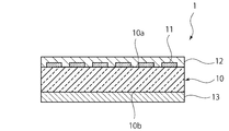
- FIG. 2 is a schematic cross-sectional view taken along line II-II in FIG.
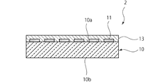
- FIG. 3 is a schematic cross-sectional view of a part of the heat ray reflective glass plate according to the second embodiment.
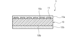
- FIG. 4 is a schematic cross-sectional view of a part of the heat ray reflective glass plate according to the third embodiment.
- FIG. 1 is a schematic plan view of a part of a heat ray reflective glass plate according to the present embodiment.
- FIG. 2 is a schematic cross-sectional view taken along line II-II in FIG.
- the heat ray reflective glass plate 1 shown in FIGS. 1 and 2 can be used as a heating device such as a stove or oven, a heating window plate, or a window glass.
- the heat ray reflective glass plate 1 includes a glass substrate 10.
- the glass substrate 10 can be formed of, for example, borate glass or heat resistant crystallized glass.
- the glass substrate 10 transmits light in the visible wavelength range (400 nm to 700 nm).
- “transmitting light in the visible wavelength region” means transmitting light in the visible wavelength region to the extent that the other side is visible, and specifically, the average light transmittance in the visible wavelength region is , 25% or more.
- the glass substrate 10 may be colorless and transparent, or may be colored and transparent.
- the thickness of the glass substrate 10 is not particularly limited as long as it is a thickness that can sufficiently ensure the mechanical strength of the heat ray reflective glass plate 1.
- the thickness of the glass substrate 10 can be about 0.5 mm to 10 mm, for example.
- the glass substrate 10 has first and second main surfaces 10a and 10b.
- the heat ray reflective glass plate 1 of the present embodiment is used by being arranged such that the second main surface 10b side faces the heat source side, that is, the high temperature side.
- a plurality of metal films 11 are formed on the first main surface 10a.
- the plurality of metal films 11 are arranged at intervals.
- the arrangement of the metal film 11 may be regular or irregular.
- an irregular arrangement not only the heat source side such as a heating device can be visually observed, but also the glass substrate can be easily provided with various shaded and decorative patterns.
- various abstract designs or concrete painting-like designs such as landscapes, animals and plants, buildings, or human figures can be applied.
- a regular arrangement is preferable.
- sequence it is preferable that it shall arrange in a matrix form, for example.
- the matrix shape is sufficient if a plurality of metal films are regularly arranged, rows and columns may be arranged in a straight line, or may be arranged in a staggered manner.
- each of the plurality of metal films 11 is circular or polygonal.
- the circle equivalent diameter of each metal film 11 is 1 mm or less.
- the equivalent circle diameter is the diameter of a circle having the same area.
- the area occupation ratio of the metal film in the region where the plurality of metal films 11 is provided on the first main surface 10a is 75% or less.
- the thickness of the metal film 11 is preferably 50 nm or more, and more preferably 200 nm or more.
- the thickness of the metal film 11 is preferably 20 ⁇ m or less, for example.
- the plurality of metal films 11 are main members responsible for the heat ray reflectivity of the heat ray reflective glass plate 1.
- the metal film 11 is preferably made of a material having a high heat ray reflectivity.
- the metal film 11 is preferably made of a metal selected from the group consisting of Al, Cu and Ag, or an alloy containing one or more metals selected from the group consisting of Al, Cu and Ag.
- a protective film 12 is formed on the first main surface 10 a so as to cover the plurality of metal films 11.
- the protective film 12 is preferably excellent in heat resistance and low in gas permeability. Moreover, it is preferable that this protective film 12 also transmits light in the visible wavelength region. Therefore, the protective film 12 is preferably made of an oxide of Si, an oxide of Ti, an oxide of Zr, an oxide of Sn, an oxide of Al or a nitride of Si.
- the thickness of the protective film 12 is not particularly limited, but can be, for example, about 50 nm to 500 nm.
- a transparent conductive film 13 that transmits light in the visible wavelength region is formed on the second main surface 10b.
- the transparent conductive film 13 substantially covers the entire second main surface 10b.
- the transparent conductive film 13 is disposed so as to overlap the plurality of metal films 11 in plan view.
- This transparent conductive film 13 has heat ray reflectivity.
- the transparent conductive film 13 can be formed of, for example, ITO (Indium Tin Oxide), ATO (Antimony Tin Oxide), FTO (Fluorine-Doped SnO2), or the like.
- the thickness of the transparent conductive film 13 is preferably 25 nm or more, and more preferably 200 nm or more.
- the metal film 11 mainly bears the heat ray reflectivity. For this reason, for example, if the metal film 11 is transformed due to oxidation or the like, the heat ray reflectivity of the heat ray reflective glass plate 1 is greatly reduced.
- the transparent conductive film 13 is provided so as to overlap the plurality of metal films 11 in plan view. For this reason, a part of the heat ray from the heat source is reflected by the transparent conductive film 13. Therefore, the intensity of the heat rays applied to the metal film 11 can be reduced. Therefore, since thermal transformation of the metal film 11 can be suppressed, excellent thermal durability can be realized.
- the metal film 11 is covered with the protective film 12. For this reason, the contact between the metal film 11 and the outside air is regulated. Therefore, thermal transformation of the metal film 11 is more effectively suppressed. Therefore, more excellent thermal durability can be realized.
- the transparent conductive film 13 also has heat ray reflectivity, the heat ray reflectivity required for the plurality of metal films 11 is low. Therefore, the area occupation ratio of the plurality of metal films 11 can be reduced, or the metal film 11 can be thinned. Therefore, the visibility through the heat ray reflective glass plate 1 can be further enhanced.
- each metal film 11 is 1 mm or less, and the area occupation ratio of the metal film in the region where the plurality of metal films 11 is provided on the first main surface 10a is 75. % Or less. Therefore, the visibility through the heat ray reflective glass plate 1 is further enhanced. From the viewpoint of further improving the visibility, each metal film 11 preferably has a diameter of 0.5 mm or less. Moreover, it is preferable that the area occupation rate of the metal film 11 in the area
- region in which the some metal film 11 of the 1st main surface 10a was provided is 20% or more.
- FIG. 3 is a schematic cross-sectional view of a part of the heat ray reflective glass plate according to the second embodiment.
- the transparent conductive film 13 is not provided on the second main surface 10b, and the protective film is formed on the first main surface 10a.
- a transparent conductive film 13 is formed.
- This heat ray reflective glass plate 2 is arranged and used such that the first main surface 10a side faces the heat source side.
- the heat ray reflective glass plate 2 of the present embodiment has excellent thermal durability like the heat ray reflective glass plate 1 of the first embodiment.
- FIG. 4 is a schematic cross-sectional view of a part of the heat ray reflective glass plate according to the third embodiment.
- transparent conductive films 13a and 13b are formed on the first and second main surfaces 10a and 10b of the glass substrate 10, respectively.
- the heat ray reflective glass plate 3 of the present embodiment suppresses the thermal deterioration of the metal film 11 even when the first and second main surfaces 10a and 10b are arranged so that either side faces the heat source side. can do.
- Example 1 A glass substrate made of crystallized glass that transmits visible light having a vertical and horizontal dimension of 30 mm and a thickness of 2.0 mm was prepared.
- Example 1 a plurality of circular Al metal films having a thickness of 0.5 mm as shown in Table 1 are formed in a matrix arrangement on the first main surface of the glass plate, and the second ITO was formed on the main surface to prepare a test piece.
- Comparative Example 1 a test piece was prepared in the same manner as in Example 1 except that the ITO film was not formed.
- the area occupation ratio of the circular Al metal film to the first main surface of the glass substrate was 50%.
- a hot plate set to 380 ° C. was prepared as a heat source.
- the sample was held for 5 minutes in a state of being placed so that the first main surface side of the test piece was in contact with the surface of the hot plate.
- the surface temperature of the surface not in contact with the hot plate (hereinafter referred to as the back surface) with respect to the surface in contact with the hot plate (hereinafter referred to as the surface) was measured with a thermocouple.
- the results are shown in Table 1 below.
- an Al metal film having a thickness of 250 nm was formed as a metal film on the back surface of the glass substrate with respect to the heat source, and the temperature of the surface of the Al metal film was 320 ° C.
- Example 1 an ITO film having a thickness of 250 nm was formed on the surface of the glass substrate so as to overlap the Al metal film.
- the temperature of the surface of the Al metal film was 310 ° C., which was higher than that of Comparative Example 1. It was low. That is, the temperature was lower in Example 1 than in Comparative Example 1 by forming the ITO film. From this result, it is understood that heat can be effectively shielded by providing the ITO film.
- Comparative Example 1 the temperature of the surface of the Al film was higher than that in Example 1 even when held for only 5 minutes, and there was a risk of causing trouble in thermal durability when held for a long period of time. .
- Example 2 About the test piece of Comparative Example 2 having the film structure shown in Table 2 and each sample piece of Example 2, crystallized glass installed in an electric furnace set in advance at 475 ° C. (Neoceram manufactured by Nippon Electric Glass) After placing the top and bottom of the film structure on the plate in the direction shown in Table 2 and holding for 24 hours, the appearance was visually observed.
- Comparative Example 2 a test piece having the same film configuration as Comparative Example 1 was used. In Comparative Example 2, since the test piece was heated for a long time, it was found that the Al metal film lost the metallic luster and was thermally deteriorated by visual observation and became white turbid (whitened).
- Example 2 in addition to the film configuration of the test piece of Example 1, a SiN (silicon nitride) film having a thickness of 100 nm was further formed on the Al metal film as a protective film. In the test piece of Example 2, the metallic luster of the Al metal film was not lost even after the test, and no change was observed.
- SiN silicon nitride
Landscapes
- Chemical & Material Sciences (AREA)
- Life Sciences & Earth Sciences (AREA)
- Engineering & Computer Science (AREA)
- Chemical Kinetics & Catalysis (AREA)
- General Chemical & Material Sciences (AREA)
- Geochemistry & Mineralogy (AREA)
- Materials Engineering (AREA)
- Organic Chemistry (AREA)
- Inorganic Chemistry (AREA)
- Surface Treatment Of Glass (AREA)
Abstract
高い熱的耐久性を有する熱線反射ガラス板を提供する。 熱線反射ガラス板1は、ガラス基板10と、金属膜11と、透明導電膜13とを備えている。ガラス基板10は、第1及び第2の主面10a、10bを有する。金属膜11は、第1の主面10aの上に形成されている。金属膜11は、相互に間隔をおいて配置されている。透明導電膜13は、平面視において金属膜11と重なるように、第1及び第2の主面10a、10bのうちの少なくとも一方の上に形成されている。
Description
本発明は、熱線反射ガラス板に関する。
従来、オーブンやストーブ、暖炉、窓ガラス等に、熱線を反射しつつ、光を透過させる透明熱線反射ガラス板が使用されている。このような熱線反射ガラス板の一例として、例えば、下記の特許文献1には、透明ガラス板の上に、Agなどの金属からなる熱線反射パターンが形成された熱線反射ガラス板が開示されている。特許文献1に記載の熱線反射ガラス板では、熱線反射率の高い金属からなる熱線反射パターンが形成されているため、高い熱線反射率が得られる。しかも、熱線反射パターンが形成されていない部分は、光が透過するため、熱線反射ガラス板の向こう側が視認可能である。
しかしながら、特許文献1に記載の熱線反射ガラス板には、熱的耐久性が低いという問題がある。
本発明は、斯かる点に鑑みて成されたものであり、その目的は、高い熱的耐久性を有する熱線反射ガラス板を提供することにある。
本発明に係る熱線反射ガラス板は、ガラス基板と、複数の金属膜と、透明導電膜とを備えている。ガラス基板は、第1及び第2の主面を有する。金属膜は、第1の主面の上に形成されている。金属膜は、相互に間隔をおいて配置されている。透明導電膜は、平面視において相互に間隔をおいた金属膜と重なるように、第1及び第2の主面のうちの少なくとも一方の上に形成されている。
相互に間隔をおいて配置されているとは、以下に示す第1、および第2の態様を含む配置である。まず、第1の態様として、平面視において、金属膜が直線、曲線あるいはこの両方が組み合わされ、ストライプ状、あるいは互いに交差した格子状の模様となり、金属膜が形成されていない面が間隔をおいて認められる場合が該当する。また、第2の態様として、平面視において、複数の不連続な構成の金属膜が主面上に規則状または不規則状となるように形成されている状態を示している。
ただ、第1の態様とする場合には、相互に間隔をおいて配置する際の金属膜の間隔に留意せねば、視覚的な干渉縞(モアレとも呼ぶ)が生じて十分な視認性が得難くなる場合もあり、このような観点から、第2の態様とする方が好ましい。
主面とは、ガラス基板の板厚方向に対向する2つの面のことである。2つの主面は、必ずしも平行でなくてもよい。すなわち必要に応じて所望の凹凸を設けた構成でもよい。
平面視においてとは、ガラス基板の板厚方向に平行な方向から見た場合を意味する。
平面視において相互に間隔をおいた金属膜と重なるようにとは、平面視した場合に金属膜と重なる部分があるということである。
金属膜の主面上の配置として、上記のような第1、あるいは第2の態様とするには、例えば次のような方法を採用すればよい。予め所定形状のマスキングを施して、成膜後にマスキングを除去する方法、成膜後にフォトリソグラフィ技術により不要箇所をエッチングで除去する方法、あるいはスクリーン印刷により膜を形成する方法などである。
本発明に係る熱線反射ガラス板では、金属膜と、透明導電膜とによって、熱線反射機能が実現されている。このため、例えば、金属膜が、熱により酸化したり、変成してしまうと、熱線反射機能が低下してしまうこととなる。しかしながら、本発明に係る熱線反射ガラス板では、透明導電膜が設けられている。このため、本発明に係る熱線反射ガラス板を、透明導電膜が高温側を向くように配置して使用することにより、金属膜に伝わる熱線の強度を低減することができる。よって、金属膜の変成を抑制することができる。従って、本発明に係る熱線反射ガラス板では、熱劣化による熱線反射機能の低下が生じにくい。すなわち、本発明に係る熱線反射ガラス板は、高い熱的耐久性を有する。
なお、本発明において、「ガラス基板」には、結晶化ガラス基板が含まれるものとする。
透明導電膜は、第2の主面の上に形成されていてもよい。その場合は、Siの酸化物、Tiの酸化物、Zrの酸化物、Snの酸化物、Alの酸化物またはSiの窒化物からなる保護膜が第1の主面の上に相互に間隔をおいて配置された金属膜を覆うように形成されていることが好ましい。この保護膜を形成することにより、相互に間隔をおいて配置された金属膜と外気とを遮断することができる。よって、金属膜の変成をより効果的に抑制することができる。従って、熱線反射ガラス板の熱的耐久性をさらに高めることができる。
透明導電膜は、第1の主面の上に相互に間隔をおいて配置された金属膜を覆うように形成されていてもよい。この場合は、相互に間隔をおいて配置された金属膜と外気とを遮蔽する保護膜としての機能を透明導電膜が兼ね備えることとなる。従って、この構成においても、相互に間隔をおいて配置された金属膜の変成をより効果的に抑制することができる。
金属膜は、熱線反射率の高い材料からなるものであることが好ましい。具体的には、金属膜は、Al,Cu及びAgからなる群から選ばれた金属、またはAl,Cu及びAgからなる群から選ばれた一種以上の金属を含む合金からなることが好ましい。金属膜をこれらの材料により形成することにより、熱線反射ガラス板の熱線反射能をさらに向上することができる。
透明導電膜も、熱線反射率の高い材料からなるものであることが好ましい。具体的には、透明導電膜は、インジウム、錫、または亜鉛を含有することが好ましく、インジウム、錫、または亜鉛を主成分とする透明導電膜であることがより好ましい。主成分とは、その金属成分が6割以上の質量含有率を有するということである。透明導電膜をこれらの材料により形成することにより、熱線反射ガラス板の熱線反射能をさらに向上することができる。
なお、相互に間隔をおいて配置された金属膜のそれぞれの表面積が大きかったり、第1の主面で相互に間隔をおいて配置された金属膜が設けられた領域における金属膜の面積占有率が高すぎたりすると、熱線反射ガラス板を通しての視認性が低下してしまう場合がある。
このため、例えば、相互に間隔をおいて配置された金属膜が、第2の態様である場合には、金属膜は、円相当直径が1mm以下の円形または多角形であることが好ましい。第1の主面の複数の金属膜が設けられた領域における金属膜の面積占有率が75%以下であることが好ましい。但し、第1の主面の複数の金属膜が設けられた領域における金属膜の面積占有率が低すぎると、熱線反射ガラス板の熱線反射能が低くなりすぎる場合がある。このため、第1の主面の金属膜が設けられた領域における金属膜の面積占有率は、20%以上であることが好ましい。
本発明によれば、高い熱的耐久性を有し、かつ視認性を有する熱線反射ガラス板を提供することができる。
以下、本発明を実施した好ましい形態の一例について説明する。但し、以下の実施形態は単なる一例である。本発明は、以下の実施形態に何ら限定されない。
(第1の実施形態)
図1は、本実施形態に係る熱線反射ガラス板の一部分の略図的平面図である。図2は、図1の線II-IIにおける略図的断面図である。図1及び図2に示す熱線反射ガラス板1は、ストーブ、オーブンなどの加熱装置、暖房の窓板や、窓ガラスとして使用可能なものである。
図1は、本実施形態に係る熱線反射ガラス板の一部分の略図的平面図である。図2は、図1の線II-IIにおける略図的断面図である。図1及び図2に示す熱線反射ガラス板1は、ストーブ、オーブンなどの加熱装置、暖房の窓板や、窓ガラスとして使用可能なものである。
図2に示すように、熱線反射ガラス板1は、ガラス基板10を備えている。ガラス基板10は、例えば、硼酸塩系ガラスや、耐熱性結晶化ガラスなどにより形成することができる。
ガラス基板10は、可視波長域(400nm~700nm)の光を透過するものである。ここで、「可視波長域の光を透過する」とは、向こう側が視認可能な程度に可視波長域の光を透過することを意味し、具体的には、可視波長域における平均光透過率が、25%以上であることを意味する。なお、ガラス基板10は、無色透明であってもよいし、有色透明であってもよい。
ガラス基板10の厚みは、熱線反射ガラス板1の機械的強度を十分に担保できる程度の厚みである限りにおいて特に限定されない。ガラス基板10の厚みは、例えば、0.5mm~10mm程度とすることができる。
ガラス基板10は、第1及び第2の主面10a、10bを有する。本実施形態の熱線反射ガラス板1は、第2の主面10b側が熱源側、すなわち高温側を向くように配置されて使用されるものである。
第1の主面10aの上には、複数の金属膜11が形成されている。これら複数の金属膜11は、相互に間隔をおいて配置されている。この金属膜11の配列は、規則的なものでも不規則なものであってもよい。不規則な配列とすることで、単に加熱装置などの熱源側を目視できるだけでなく、ガラス基板に様々な濃淡のある装飾性に富んだ模様をつけることが容易になる。具体的には、様々な抽象的デザイン、あるいは風景、動植物、建造物、あるいは人物像などの具象的な絵画調のデザインを施すこともできる。ただ、作製に要する労力や経済性等を考慮すると、規則的な配列とすることが好ましい。また規則的な配列としては、例えばマトリクス状に配置されているものとすることが好ましい。なお、本発明においてマトリクス状とは、複数の金属膜が規則的に配列していればよく、行と、列とを直線状に揃えて並んでいてもよく、千鳥状に並んでいてもよい。本実施形態では、複数の金属膜11のそれぞれは、円形または多角形である。各金属膜11の円相当直径は、1mm以下である。ちなみに、円相当直径は、同面積の円についての直径のことである。また、第1の主面10aの複数の金属膜11が設けられた領域における金属膜の面積占有率は、75%以下である。金属膜11の厚みは、例えば、50nm以上であることが好ましく、200nm以上であることがより好ましい。金属膜11の厚みは、例えば、20μm以下であることが好ましい。
複数の金属膜11は、熱線反射ガラス板1の熱線反射能を担う主たる部材である。このため、金属膜11は、熱線反射率の高い材料からなることが好ましい。具体的には、金属膜11は、Al,Cu及びAgからなる群から選ばれた金属、またはAl,Cu及びAgからなる群から選ばれた一種以上の金属を含む合金からなることが好ましい。
金属膜11の厚みは、特に限定されないが、例えば、200nm~20μm(=2×10⁴nm)程度とすることができる。
第1の主面10aの上には、複数の金属膜11を覆うように、保護膜12が形成されている。保護膜12は、耐熱性に優れ、かつ気体透過性が低いものであることが好ましい。また、この保護膜12も可視波長域の光を透過させるものであることが好ましい。このため、保護膜12は、Siの酸化物、Tiの酸化物、Zrの酸化物、Snの酸化物、Alの酸化物またはSiの窒化物からなるものであることが好ましい。
保護膜12の厚みは、特に限定されないが、例えば、50nm~500nm程度とすることができる。
一方、第2の主面10bの上には、可視波長域の光を透過する透明導電膜13が形成されている。この透明導電膜13により第2の主面10bの実質的に全体が覆われている。このため、本実施形態では、平面視において、透明導電膜13は、複数の金属膜11と重なるように配置されている。この透明導電膜13は、熱線反射能を有するものである。透明導電膜13は、例えば、ITO(Indium Tin Oxide)や、ATO(Antimony Tin Oxide)、FTO(Fluorine-Doped SnO2)などにより形成することができる。
透明導電膜13の厚みは、25nm以上であることが好ましく、200nm以上であることがより好ましい。また、透明導電膜13の厚みは、1μm(=1000nm)以下であることが好ましい。
上述のように、熱線反射ガラス板1においては、金属膜11が主として熱線反射能を担っている。このため、例えば、金属膜11が酸化するなどして変成してしまうと、熱線反射ガラス板1の熱線反射能が大きく低下してしまう。
ここで、例えば上記特許文献1に記載の熱線反射ガラス板のように、透明導電膜が設けられていない場合は、金属膜に強い熱線が照射される。このため、金属膜が酸化するなどして変成しやすい。従って、十分に優れた熱的耐久性を実現することは困難である。
それに対して、本実施形態の熱線反射ガラス板1では、透明導電膜13が平面視において複数の金属膜11と重なるように設けられている。このため、熱源からの熱線の一部が透明導電膜13により反射される。よって、金属膜11に照射される熱線の強度を弱くすることができる。従って、金属膜11の熱変成を抑制できるので、優れた熱的耐久性を実現することができる。
さらに、本実施形態では、金属膜11が保護膜12により覆われている。このため、金属膜11と外気との接触が規制されている。よって、金属膜11の熱変成がより効果的に抑制されている。従って、より優れた熱的耐久性を実現することができる。
また、本実施形態では、透明導電膜13も熱線反射能を有しているため、複数の金属膜11に要求される熱線反射能が低い。よって、複数の金属膜11の面積占有率を低くしたり、金属膜11を薄くしたりすることが可能となる。従って、熱線反射ガラス板1を通した視認性をより高めることができる。
特に、本実施形態では、各金属膜11の円相当直径が1mm以下とされており、かつ第1の主面10aの複数の金属膜11が設けられた領域における金属膜の面積占有率が75%以下とされている。従って、熱線反射ガラス板1を通した視認性がさらに高められている。視認性のさらなる向上を図る観点からは、各金属膜11の直径は0.5mm以下であることが好ましい。また、第1の主面10aの複数の金属膜11が設けられた領域における金属膜11の面積占有率は、75%以下であることが好ましい。但し、第1の主面10aの複数の金属膜11が設けられた領域における金属膜11の面積占有率が低すぎると、熱線反射ガラス板1の熱線反射能が低くなりすぎる場合がある。このため、第1の主面10aの複数の金属膜11が設けられた領域における金属膜11の面積占有率は、20%以上であることが好ましい。
以下、本発明を実施した好ましい形態の他の例について説明する。なお、以下の説明において、上記第1の実施形態と実質的に共通の機能を有する部材を共通の符号で参照し、説明を省略する。
(第2の実施形態)
図3は、第2の実施形態に係る熱線反射ガラス板の一部分の略図的断面図である。図3に示すように、本実施形態の熱線反射ガラス板2では、第2の主面10bの上に透明導電膜13が設けられておらず、第1の主面10aの上に、保護膜12に代えて透明導電膜13が形成されている。この熱線反射ガラス板2は、第1の主面10a側が熱源側を向くように配置されて使用される。
図3は、第2の実施形態に係る熱線反射ガラス板の一部分の略図的断面図である。図3に示すように、本実施形態の熱線反射ガラス板2では、第2の主面10bの上に透明導電膜13が設けられておらず、第1の主面10aの上に、保護膜12に代えて透明導電膜13が形成されている。この熱線反射ガラス板2は、第1の主面10a側が熱源側を向くように配置されて使用される。
本実施形態の熱線反射ガラス板2においても、透明導電膜13により金属膜11に照射する熱線の強度が低減されている。また、透明導電膜13により、金属膜11が外気から隔離されている。従って、本実施形態の熱線反射ガラス板2は、上記第1の実施形態の熱線反射ガラス板1と同様に、優れた熱的耐久性を有している。
(第3の実施形態)
図4は、第3の実施形態に係る熱線反射ガラス板の一部分の略図的断面図である。図4に示すように、本実施形態の熱線反射ガラス板3では、ガラス基板10の第1及び第2の主面10a、10bのそれぞれの上に透明導電膜13a、13bが形成されている。このため、本実施形態の熱線反射ガラス板3は、第1及び第2の主面10a、10bのどちら側が熱源側を向くように配置した場合であっても、金属膜11の熱劣化を抑制することができる。
図4は、第3の実施形態に係る熱線反射ガラス板の一部分の略図的断面図である。図4に示すように、本実施形態の熱線反射ガラス板3では、ガラス基板10の第1及び第2の主面10a、10bのそれぞれの上に透明導電膜13a、13bが形成されている。このため、本実施形態の熱線反射ガラス板3は、第1及び第2の主面10a、10bのどちら側が熱源側を向くように配置した場合であっても、金属膜11の熱劣化を抑制することができる。
本発明の第1の実施形態について、その性能を確認するため、以下の評価を行った。
(実験例1)
縦横寸法が各々30mm、厚さ2.0mmの可視光を透過する結晶化ガラス製のガラス基板を準備した。実施例1においては、このガラス板の第1の主面上に、表1に示すような膜厚の直径0.5mmの円形の複数のAl金属膜をマトリクス状配列で形成し、第2の主面上にはITOを形成し、試験片を作製した。比較例1では、ITO膜を形成していない以外は、実施例1と同様に試験片を作製した。
縦横寸法が各々30mm、厚さ2.0mmの可視光を透過する結晶化ガラス製のガラス基板を準備した。実施例1においては、このガラス板の第1の主面上に、表1に示すような膜厚の直径0.5mmの円形の複数のAl金属膜をマトリクス状配列で形成し、第2の主面上にはITOを形成し、試験片を作製した。比較例1では、ITO膜を形成していない以外は、実施例1と同様に試験片を作製した。
この円形状のAl金属膜のガラス基板の第1の主面に対するに面積占有率は、50%であった。
次に熱源として、380℃となるように設定されたホットプレートを準備した。このホットプレートの表面上に試験片の第1の主面側が接触するように載置した状態で、5分間保持した。その後、ホットプレートと接触している面(以後、表面と呼ぶ)に対して、ホットプレートと接触していない面側(以後、裏面と呼ぶ)の表面の温度を熱電対で計測した。結果を下記の表1に示す。

比較例1の試験片は、熱源に対してガラス基板の裏面に金属膜として250nmの厚みのAl金属膜が形成されているが、このAl金属膜の表面の温度は320℃であった。
一方、実施例1は、ガラス基板の表面にAl金属膜と重なるように、250nmの厚みのITO膜を形成しているが、Al金属膜の表面の温度は310℃で、比較例1よりも低かった。すなわち、ITO膜が形成されることにより実施例1では、比較例1よりも温度が低くなった。この結果から、ITO膜を設けることにより、効果的に熱を遮蔽できることが分かる。
一方、比較例1は、僅か5分の保持でも実施例1よりもAl膜の表面の温度が高くなり、長期間に亘る保持では、熱的な耐久性に支障の発生する危険性があった。
(実験例2)
表2に示す膜構成の比較例2の試験片、及び実施例2のそれぞれの試料片について、475℃に予め設定した電気炉内に設置した結晶化ガラス(日本電気硝子製 ネオセラム)
板上に膜構成の天地を表2に示す方向にして載置して24時間保持した後、その外観を目視観察した。
表2に示す膜構成の比較例2の試験片、及び実施例2のそれぞれの試料片について、475℃に予め設定した電気炉内に設置した結晶化ガラス(日本電気硝子製 ネオセラム)
板上に膜構成の天地を表2に示す方向にして載置して24時間保持した後、その外観を目視観察した。
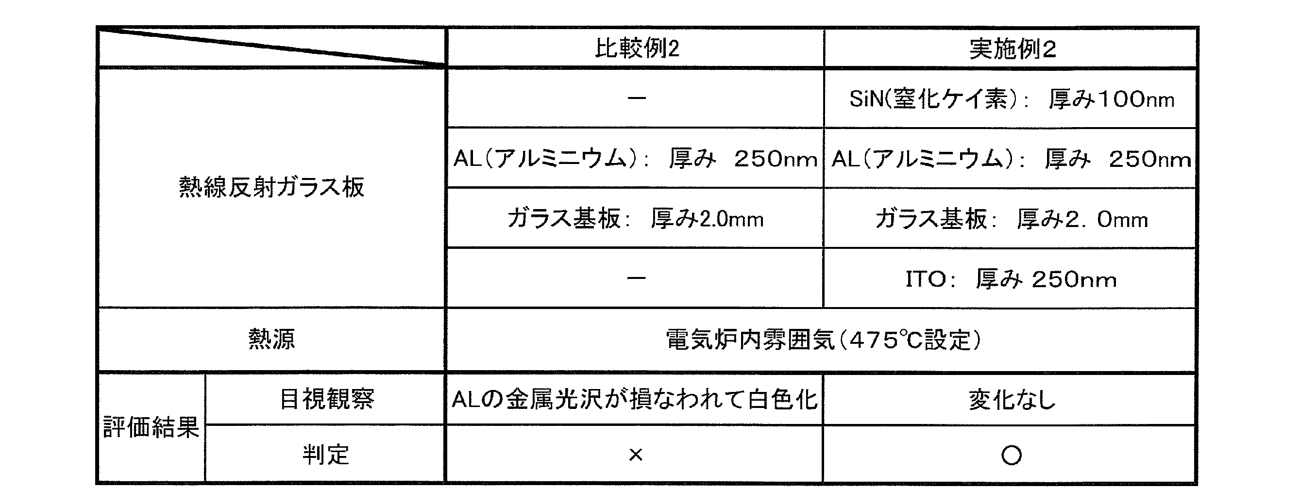
比較例2では、比較例1と同じ膜構成の試験片を使用した。比較例2は、試験片が長時間に亘り加熱されたため、Al金属膜が金属光沢を失い、目視観察によって熱劣化して白濁(白色化)していることが判明した。
一方、実施例2では、実施例1の試験片の膜構成に加えて、さらに保護膜としてAl金属膜上に厚み100nmのSiN(窒化ケイ素)膜を形成した。この実施例2の試験片は、試験後でもAl金属膜の金属光沢は失われず、何ら変化は認められなかった。
1~3…熱線反射ガラス板
10…ガラス基板
10a…第1の主面
10b…第2の主面
11…金属膜
12…保護膜
13、13a、13b…透明導電膜
10…ガラス基板
10a…第1の主面
10b…第2の主面
11…金属膜
12…保護膜
13、13a、13b…透明導電膜
Claims (7)
- 第1及び第2の主面を有するガラス基板と、
前記第1の主面の上に形成されており、相互に間隔をおいて配置された金属膜と、
平面視において前記金属膜と重なるように、前記第1及び第2の主面のうちの少なくとも一方の上に形成されている透明導電膜と、
を備える熱線反射ガラス板。 - 前記透明導電膜は、前記第2の主面の上に形成されており、
前記第1の主面の上に前記金属膜を覆うように形成されており、Siの酸化物、Tiの酸化物、Zrの酸化物、Snの酸化物、Alの酸化物またはSiの窒化物からなる保護膜をさらに備える、請求項1に記載の熱線反射ガラス板。 - 前記透明導電膜は、前記第1の主面の上に前記金属膜を覆うように形成されている、請求項1に記載の熱線反射ガラス板。
- 前記金属膜は、Al,Cu及びAgからなる群から選ばれた金属、またはAl,Cu及びAgからなる群から選ばれた一種以上の金属を含む合金からなる、請求項1~3のいずれか一項に記載の熱線反射ガラス板。
- 前記透明導電膜は、インジウム、錫、または亜鉛を含有する、請求項1~4のいずれか一項に記載の熱線反射ガラス板。
- 前記金属膜は、円相当直径が1mm以下の円形または多角形である、請求項1~5のいずれか一項に記載の熱線反射ガラス板。
- 前記第1の主面の前記金属膜が設けられた領域における前記金属膜の面積占有率が75%以下である、請求項1~6のいずれか一項に記載の熱線反射ガラス板。
Applications Claiming Priority (2)
| Application Number | Priority Date | Filing Date | Title |
|---|---|---|---|
| JP2011048840A JP2012184140A (ja) | 2011-03-07 | 2011-03-07 | 熱線反射ガラス板 |
| JP2011-048840 | 2011-03-07 |
Publications (1)
| Publication Number | Publication Date |
|---|---|
| WO2012121035A1 true WO2012121035A1 (ja) | 2012-09-13 |
Family
ID=46798003
Family Applications (1)
| Application Number | Title | Priority Date | Filing Date |
|---|---|---|---|
| PCT/JP2012/054695 Ceased WO2012121035A1 (ja) | 2011-03-07 | 2012-02-27 | 熱線反射ガラス板 |
Country Status (2)
| Country | Link |
|---|---|
| JP (1) | JP2012184140A (ja) |
| WO (1) | WO2012121035A1 (ja) |
Cited By (1)
| Publication number | Priority date | Publication date | Assignee | Title |
|---|---|---|---|---|
| WO2019102813A1 (ja) * | 2017-11-24 | 2019-05-31 | 国立大学法人東北大学 | 選択波長反射体 |
Families Citing this family (2)
| Publication number | Priority date | Publication date | Assignee | Title |
|---|---|---|---|---|
| LU100018B1 (en) * | 2017-01-11 | 2018-08-14 | Luxembourg Inst Science & Tech List | Infrared reflective and electrical conductive composite film and manufacturing method thereof |
| JP7229091B2 (ja) * | 2019-05-09 | 2023-02-27 | 大阪瓦斯株式会社 | 光制御体 |
Citations (4)
| Publication number | Priority date | Publication date | Assignee | Title |
|---|---|---|---|---|
| JPS56130347A (en) * | 1980-03-19 | 1981-10-13 | Nitto Electric Ind Co | Article with composite film |
| JPS58140344A (ja) * | 1982-02-10 | 1983-08-20 | Matsushita Electric Ind Co Ltd | 熱線反射ガラス |
| JP2008013420A (ja) * | 2006-07-10 | 2008-01-24 | Fujikura Ltd | 熱線反射ガラス |
| JP2008508173A (ja) * | 2004-07-30 | 2008-03-21 | ユーロケラ ソシエテ オン ノーム コレクティフ | 暖炉のインサート又はストーブ型の機器のための、ガラス材料で作られた板 |
-
2011
- 2011-03-07 JP JP2011048840A patent/JP2012184140A/ja not_active Withdrawn
-
2012
- 2012-02-27 WO PCT/JP2012/054695 patent/WO2012121035A1/ja not_active Ceased
Patent Citations (4)
| Publication number | Priority date | Publication date | Assignee | Title |
|---|---|---|---|---|
| JPS56130347A (en) * | 1980-03-19 | 1981-10-13 | Nitto Electric Ind Co | Article with composite film |
| JPS58140344A (ja) * | 1982-02-10 | 1983-08-20 | Matsushita Electric Ind Co Ltd | 熱線反射ガラス |
| JP2008508173A (ja) * | 2004-07-30 | 2008-03-21 | ユーロケラ ソシエテ オン ノーム コレクティフ | 暖炉のインサート又はストーブ型の機器のための、ガラス材料で作られた板 |
| JP2008013420A (ja) * | 2006-07-10 | 2008-01-24 | Fujikura Ltd | 熱線反射ガラス |
Cited By (5)
| Publication number | Priority date | Publication date | Assignee | Title |
|---|---|---|---|---|
| WO2019102813A1 (ja) * | 2017-11-24 | 2019-05-31 | 国立大学法人東北大学 | 選択波長反射体 |
| JPWO2019102813A1 (ja) * | 2017-11-24 | 2020-12-03 | 国立大学法人東北大学 | 選択波長反射体 |
| JP7345783B2 (ja) | 2017-11-24 | 2023-09-19 | 国立大学法人東北大学 | 選択波長反射体 |
| JP2023133313A (ja) * | 2017-11-24 | 2023-09-22 | 国立大学法人東北大学 | 選択波長反射体 |
| JP7618286B2 (ja) | 2017-11-24 | 2025-01-21 | 国立大学法人東北大学 | 選択波長反射体 |
Also Published As
| Publication number | Publication date |
|---|---|
| JP2012184140A (ja) | 2012-09-27 |
Similar Documents
| Publication | Publication Date | Title |
|---|---|---|
| CA2948639C (en) | Ig window unit for preventing bird collisions | |
| JP6328122B2 (ja) | 低い可視光線透過率を有する低放射率被覆製品 | |
| JP6181210B2 (ja) | 熱放射反射コーティングを有する板ガラス | |
| US12110252B2 (en) | Low-e coated architectural glass having high selectivity | |
| JP2014524405A (ja) | 熱処理が可能な低放射ガラス及びその製造方法 | |
| JP2010013345A (ja) | 熱放射反射配列構造体、同製造方法、及び同利用方法 | |
| SA515370185B1 (ar) | تزجيج ذو انبعاثية منخفضة ومضاد للطاقة الشمسية | |
| JP2008518875A (ja) | 拡散バリアを有するガラスセラミック製品及び拡散バリアを有するガラスセラミック製品の製造方法 | |
| JP4501152B2 (ja) | ガラス物品 | |
| KR20170077217A (ko) | 반사 방지 코팅된 유리 제품 | |
| JP2019529308A (ja) | 窓戸用機能性建材 | |
| JP2016530202A (ja) | 熱処理可能な被覆ガラス板 | |
| KR102939952B1 (ko) | 판형 물품과 그 용도, 및 이를 포함하는 가전제품 | |
| WO2012121035A1 (ja) | 熱線反射ガラス板 | |
| JP2018135260A (ja) | コーティングされた保護ウインドウ | |
| CN114436541A (zh) | 包括衬底和涂层的玻璃或玻璃陶瓷元件及制造方法和用途 | |
| JP6940597B2 (ja) | 低放射コーティングを含む窓戸用機能性建材 | |
| KR101975637B1 (ko) | 저방사 유리 | |
| CN113365954B (zh) | 玻璃陶瓷制品 | |
| JP6468195B2 (ja) | 薄膜形成方法およびコーティングガラス | |
| JP5160117B2 (ja) | 着色ガラス | |
| CN104628266A (zh) | 单层防火玻璃的制备方法 | |
| JP6709544B2 (ja) | 調理器用トッププレート | |
| JP7029567B1 (ja) | シリカ熱反射板 | |
| US10194493B2 (en) | Household appliance apparatus |
Legal Events
| Date | Code | Title | Description |
|---|---|---|---|
| 121 | Ep: the epo has been informed by wipo that ep was designated in this application |
Ref document number: 12755142 Country of ref document: EP Kind code of ref document: A1 |
|
| NENP | Non-entry into the national phase |
Ref country code: DE |
|
| 122 | Ep: pct application non-entry in european phase |
Ref document number: 12755142 Country of ref document: EP Kind code of ref document: A1 |