WO2012121031A1 - 含窒素炭素化合物 - Google Patents
含窒素炭素化合物 Download PDFInfo
- Publication number
- WO2012121031A1 WO2012121031A1 PCT/JP2012/054606 JP2012054606W WO2012121031A1 WO 2012121031 A1 WO2012121031 A1 WO 2012121031A1 JP 2012054606 W JP2012054606 W JP 2012054606W WO 2012121031 A1 WO2012121031 A1 WO 2012121031A1
- Authority
- WO
- WIPO (PCT)
- Prior art keywords
- nitrogen
- containing carbon
- carbon compound
- compound
- electrode
- Prior art date
- Legal status (The legal status is an assumption and is not a legal conclusion. Google has not performed a legal analysis and makes no representation as to the accuracy of the status listed.)
- Ceased
Links
Images






Classifications
-
- C—CHEMISTRY; METALLURGY
- C01—INORGANIC CHEMISTRY
- C01B—NON-METALLIC ELEMENTS; COMPOUNDS THEREOF; METALLOIDS OR COMPOUNDS THEREOF NOT COVERED BY SUBCLASS C01C
- C01B21/00—Nitrogen; Compounds thereof
- C01B21/06—Binary compounds of nitrogen with metals, with silicon, or with boron, or with carbon, i.e. nitrides; Compounds of nitrogen with more than one metal, silicon or boron
- C01B21/0605—Binary compounds of nitrogen with carbon
-
- C—CHEMISTRY; METALLURGY
- C01—INORGANIC CHEMISTRY
- C01P—INDEXING SCHEME RELATING TO STRUCTURAL AND PHYSICAL ASPECTS OF SOLID INORGANIC COMPOUNDS
- C01P2002/00—Crystal-structural characteristics
- C01P2002/70—Crystal-structural characteristics defined by measured X-ray, neutron or electron diffraction data
- C01P2002/72—Crystal-structural characteristics defined by measured X-ray, neutron or electron diffraction data by d-values or two theta-values, e.g. as X-ray diagram
-
- C—CHEMISTRY; METALLURGY
- C01—INORGANIC CHEMISTRY
- C01P—INDEXING SCHEME RELATING TO STRUCTURAL AND PHYSICAL ASPECTS OF SOLID INORGANIC COMPOUNDS
- C01P2002/00—Crystal-structural characteristics
- C01P2002/70—Crystal-structural characteristics defined by measured X-ray, neutron or electron diffraction data
- C01P2002/78—Crystal-structural characteristics defined by measured X-ray, neutron or electron diffraction data by stacking-plane distances or stacking sequences
-
- C—CHEMISTRY; METALLURGY
- C01—INORGANIC CHEMISTRY
- C01P—INDEXING SCHEME RELATING TO STRUCTURAL AND PHYSICAL ASPECTS OF SOLID INORGANIC COMPOUNDS
- C01P2002/00—Crystal-structural characteristics
- C01P2002/80—Crystal-structural characteristics defined by measured data other than those specified in group C01P2002/70
- C01P2002/82—Crystal-structural characteristics defined by measured data other than those specified in group C01P2002/70 by IR- or Raman-data
Definitions
- the present invention relates to a novel nitrogen-containing carbon compound and a method for producing the same. More specifically, the present invention relates to a novel nitrogen-containing carbon compound having a graphite structure and a method for producing the same.
- Patent Document 2 coal-based binder pitch and nitrogen-containing polymer compound
- Patent Document 3 coal-based binder pitch and nitrogen-containing polymer compound
- Patent Document 1 does not mention a method for producing a nitrogen-containing carbon compound.
- Patent Document 2 Patent Documents 3 and 4 since a polymer is used as a raw material compound serving as a carbon supply source, it is difficult to expect the growth of a graphite structure.
- problems such as the necessity of using a high temperature of 1000 ° C. and the necessity of installing relatively large-scale incidental equipment in the reactor because gas is generated during the production reaction of the nitrogen-containing carbon compound. there were.
- the obtained nitrogen-containing compound has a small graphite structure and a large amorphous structure, there is a problem that resistance to oxygen is low.
- the present invention has been made in view of the above problems, and an object thereof is to efficiently supply a novel nitrogen-containing carbon compound having a graphite structure on an industrial scale.
- the present inventors have found that a novel nitrogen-containing carbon compound having a graphite structure can be produced by discharging between carbon electrodes in an organic liquid medium containing a nitrogen-containing organic compound, and have completed the present invention. That is, the present invention provides the following.
- a method for producing a nitrogen-containing carbon compound according to [1] above comprising the step of discharging between carbon electrodes in an organic liquid medium to produce the nitrogen-containing carbon compound in the liquid medium, The manufacturing method, wherein the organic liquid medium contains at least one nitrogen-containing organic compound as a component.
- the nitrogen-containing organic compound is a nitrogen-containing aromatic organic compound.
- a novel nitrogen-containing carbon compound having a graphite structure can be efficiently obtained using a simple production facility.
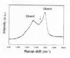
- FIG. 1 shows the Raman spectrum of the nitrogen-containing carbon compound obtained from Example 1.
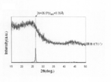
- FIG. 2 shows a powder X-ray diffraction pattern of the nitrogen-containing carbon compound obtained from Example 1.
- FIG. 3 shows the Raman spectrum of the nitrogen-containing carbon compound obtained from Example 2.
- FIG. 4 shows a powder X-ray diffraction pattern of the nitrogen-containing carbon compound obtained from Example 2.
- FIG. 5 shows the Raman spectrum of the nitrogen-containing carbon compound obtained from Example 3.
- FIG. 6 shows a powder X-ray diffraction pattern of the nitrogen-containing carbon compound obtained from Example 3.
- FIG. 7 shows the Raman spectrum of the nitrogen-containing carbon compound obtained from Example 4.
- FIG. 8 shows a powder X-ray diffraction pattern of the nitrogen-containing carbon compound obtained from Example 4.
- FIG. 1 shows the Raman spectrum of the nitrogen-containing carbon compound obtained from Example 1.
- FIG. 2 shows a powder X-ray diffraction pattern of the nitrogen-containing carbon compound obtained from Example 1.
- FIG. 3 shows
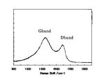
- FIG. 9 shows the Raman spectrum of the nitrogen-containing carbon compound obtained from Comparative Example 1.
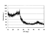
- FIG. 10 shows a powder X-ray diffraction pattern of the nitrogen-containing carbon compound obtained from Comparative Example 1.
- FIG. 11 shows a three-pole rotating electrode cell for measuring oxygen reduction activity using a nitrogen-containing carbon compound as a test electrode.
- the nitrogen-containing carbon compound of the present invention can be obtained by discharging between carbon electrodes in an organic liquid medium containing a nitrogen-containing organic compound.
- the organic liquid medium may be only the nitrogen-containing organic compound as long as it is liquid.
- the nitrogen-containing organic compound used is preferably a liquid under the temperature and pressure at which discharge is performed, and nitrogen-containing aromatic compounds such as pyridine, quinoline, isoquinoline, methylpyridine, lutidine, aminopyridine, and pyrrole, aniline, Aromatic amines such as monomethylaniline, monoethylaniline, dimethylaniline, diethylaniline, nitrogen-containing cyclic compounds such as piperidine, pyrrolidine, aliphatic amines such as trimethylamine, triethylamine, tributylamine, diethylamine, dibutylamine, ethanolamine, An amino alcohol such as N-methylethanolamine, diethanolamine, and triethanolamine can be used.
- nitrogen-containing aromatic compounds such as
- a nitrogen-containing aromatic compound an aromatic amine, or the like in consideration of the stability of the nitrogen-containing organic compound and the ease of growth of the graphite structure of the product nitrogen-containing carbon compound.
- aromatic amine an aromatic amine, or the like in consideration of the stability of the nitrogen-containing organic compound and the ease of growth of the graphite structure of the product nitrogen-containing carbon compound.
- the organic liquid medium used in the present invention may contain an organic compound other than the nitrogen-containing organic compound (that is, an organic compound not containing nitrogen).
- the nitrogen-free organic compound is preferably liquid at the temperature and pressure at which discharge is performed, for example, aliphatic hydrocarbons such as hexane, heptane, octane, decane, cyclohexane, cyclooctane, benzene, toluene, xylene , Aromatic hydrocarbons such as mesitylene and naphthalene, alcohols such as methanol, ethanol and propanol, and ethers such as diethyl ether, dibutyl ether, tetrahydrofuran and tetrahydropyran.
- the organic compound not containing nitrogen may be used alone or in combination.
- the mixing ratio of the nitrogen-containing organic compound and the organic compound not containing nitrogen is not particularly limited, but is usually included as a molar ratio in consideration of the amount of nitrogen introduced into the product nitrogen-containing carbon compound.
- Nitrogen compound Organic compound containing no nitrogen is mixed in the range of 1:10 to 10000: 1, preferably in the range of 1: 1 to 1000: 1.
- a carbon electrode is used as an electrode for discharging.
- the type of carbon material used for the electrode any of graphite, amorphous carbon, and glassy carbon may be used.
- the same or different carbon materials may be used as materials for the anode and cathode electrodes. In consideration of the discharge efficiency and the cost of the electrode material, it is preferable to use graphite for the electrode.
- the shape of the carbon electrode is not particularly limited, and a plate shape, a rod shape, a needle shape, or the like can be used.
- the size of the electrode is also not particularly limited.
- a plate shape a flat surface having a length of 10 mm to 1 m and a thickness of 0.2 mm to 20 mm.
- a rod shape a square cross section having a side of 1 mm to 30 mm
- a circular cross section of 1 mm ⁇ to 3 mm ⁇ and a length of 1 mm to 1 m can be used.
- the carbon electrode Since the purity of the carbon electrode affects the content of impurities incorporated into the produced nitrogen-containing carbon compound, it is preferable that the carbon electrode does not contain metals or other elements, and is usually 99% or more, more preferably 99.9%. The thing of the above purity is used.
- a voltage is applied between the carbon electrodes to discharge.
- the voltage at this time is not particularly limited as long as it can be discharged in an organic liquid medium containing a nitrogen-containing compound. Usually, it is in the range of 10 to 800V, preferably in the range of 20 to 500V, more preferably in the range of 50 to 300V.
- an excessive voltage is applied, the production rate of the target nitrogen-containing carbon compound becomes rate-determining and the energy efficiency is lowered. If the voltage is too low, the discharge is not stable and the generation efficiency is lowered, which is not preferable.
- the current is related to the amount of product produced, and is usually in the range of 5 to 200 A, preferably in the range of 10 to 180 A, and more preferably in the range of 20 to 160 A.
- an excessive current is passed, the production rate of the target nitrogen-containing carbon compound becomes rate-determining, and the energy efficiency is lowered.
- the current value is small, the yield of the obtained nitrogen-containing carbon compound is reduced and the productivity is lowered.
- the current and voltage patterns during discharge are not particularly limited, and any waveform such as a sine wave, a rectangular wave, or a triangular wave may be used. It is preferable to use a rectangular wave because discharge occurs rapidly and uniformly in the reaction field and the uniformity of the structure and composition of the resulting nitrogen-containing carbon compound is enhanced.
- either direct current or alternating current may be used.
- the current is a rectangular wave, it is preferable to use a direct current because the waveform control is easier.
- the discharge method may be either pulse discharge or continuous discharge.
- the duration of discharge is not particularly limited, and varies depending on which of pulse discharge and continuous discharge is adopted. In order to grow the graphite structure of the nitrogen-containing carbon compound relatively large, it is better to keep the discharge duration long. On the contrary, in order to make the graphite structure as small as possible, it is better to shorten the discharge duration.
- the discharge duration is preferably 1 ⁇ sec or more, and in order to make the discharge more stable, the pulse width is more preferably set to 10 ⁇ sec or more.
- the pulse pause time is usually in the range of 1 ⁇ sec to 100 msec, more preferably in the range of 2 ⁇ sec to 50 msec. If the pulse pause time is too long, the amount of nitrogen-containing carbon compound produced is reduced. On the other hand, if the pulse pause time is too short, the uniformity of the structure and composition of the resulting nitrogen-containing carbon compound is undesirable.
- the discharge duration can be arbitrarily set in seconds, minutes or hours as necessary. Considering the load limitation on the duration of 1 minute or less is preferable.
- the atmosphere in the reaction system in the production method of the present invention is not particularly limited, and can be produced under any pressure condition from a pressurized state to a reduced pressure state. This is not preferable because operability and convenience are impaired. In addition, when the reactivity of the gas is high, it is necessary to consider operational safety, which is not preferable. Therefore, it is usually carried out under an inert gas such as nitrogen or argon at atmospheric pressure.
- the temperature in the reaction system in the production method of the present invention depends on the type, nature and state of the organic liquid medium used, but is usually in the range of 0 to 200 ° C., preferably in the range of 5 to 160 ° C., operability, In consideration of safety, it is more preferably set in the range of 10 to 140 ° C.
- the nitrogen-containing carbon compound of the present invention can be easily separated and recovered by filtration and / or evaporation of an organic liquid medium.
- the nitrogen content of the nitrogen-containing carbon compound of the present invention is usually 1 wt% or more and 20 wt% or less, preferably 2 wt% or more and 15 wt% or less, more preferably 3 wt% or more and 12 wt% or less. And more preferably 3.5 wt% or more and 10 wt% or less.
- the nitrogen-containing carbon compound of the present invention has a d002 plane interval of 3.40 mm or more and 4.00 mm or less, preferably 3.40 mm or more, based on the 2 ⁇ value at the peak top of the diffraction intensity measured by the powder X-ray diffraction method. It can be confirmed that it has a graphite structure of 3.90 mm or less, more preferably 3.45 mm or more and 3.80 mm or less, and further preferably 3.50 mm or more and 3.76 mm or less.
- the Raman spectrum of the nitrogen-containing carbon compound of the present invention is measured, it can be confirmed that there are at least three peaks in the wave number range of 1200 to 1600 cm ⁇ 1 (FIG. 1, FIG. 3, FIG. 5 and FIG. FIG. 7).
- the peak appearing in this wave number region is derived from the presence of nitrogen incorporated as a constituent atom in the graphite structure in addition to the presence of the graphite structure. It can be said that the chemical structure of the nitrogen-containing carbon compound obtained by the production method of the present invention is characterized.
- the peak intensity derived from the D band appearing in the vicinity of 1350 cm -1 is at a constant rate or less with respect to the peak intensity derived from the G band appearing in the vicinity of 1550 cm -1
- the ratio (D / G) of the peak intensity derived from the D band to the peak intensity derived from the G band is preferably 0.80 or less, and more preferably 0.75 or less.
- D / G is preferably 0.30 or more, and more preferably 0.35 or more.
- the peak intensity of the Raman spectrum means a value based on the peak intensity at 1000 cm ⁇ 1 , that is, the difference from the peak intensity at 1000 cm ⁇ 1 .
- Powder X-ray diffraction measurement was performed using Rigaku RINT-2500VHF (CuK ⁇ ).
- the measurement of the Raman spectroscopic spectrum was carried out using a micro laser Raman spectroscope LabRAM ⁇ ARAMIS manufactured by Horiba.
- the carbon electrode used was C Rod C-076211 (manufactured by Nilaco, 8 mm ⁇ , length 100 mm).
- Example 1 Take 50 ml of pyridine (manufactured by Wako Pure Chemicals, special grade reagent) in a 100 ml beaker, immerse an 8 mm ⁇ carbon electrode and a 10 mm ⁇ 5 mm ⁇ 2 mm carbon plate electrode in pyridine, set the distance between the electrodes to 1 mm, and connect each electrode to a DC power supply did.
- the reactor was placed in a nitrogen box, and the inside of the box was purged with nitrogen, and then 200 V was applied between both electrodes.
- the discharge duration was set to 250 ⁇ s and the resting time was set to 30 milliseconds, and a current of 60 A was applied as a rectangular wave.
- the number of discharges was calculated with an oscilloscope and a discharge counter, and 100,000 discharges were performed.
- 100.5 mg of nitrogen-containing carbon compound was obtained, and as a result of elemental analysis, it was found to contain 84.6% by weight of carbon, 0.7% by weight of hydrogen, and 6.2% by weight of nitrogen. did.
- the Raman shift wave number of the peak indicated by the arrow was 1520 cm ⁇ 1 .
- the ratio D / G between the peak intensity of the D band (peak top near 1350 cm ⁇ 1 ) and the peak intensity of the G band (peak top near 1550 cm ⁇ 1 ) was 0.70.
- Example 2 Take 50 ml of aniline (manufactured by Wako Pure Chemicals, special grade reagent) in a 100 ml beaker, immerse an 8 mm ⁇ carbon electrode and a 10 mm ⁇ 5 mm ⁇ 2 mm carbon plate electrode in aniline, set the distance between the electrodes to 1 mm, and connect each electrode to a DC power supply did.
- the reactor was placed in a nitrogen box, and the inside of the box was purged with nitrogen, and then 200 V was applied between both electrodes.
- the discharge duration was set to 250 ⁇ s and the resting time was set to 30 milliseconds, and a current of 60 A was applied as a rectangular wave.
- the number of discharges was calculated with an oscilloscope and a discharge counter, and 100,000 discharges were performed.
- By filtering the reaction solution 166.1 mg of nitrogen-containing carbon compound was obtained, and as a result of elemental analysis, it was found to contain 86.9% by weight of carbon, 0.5% by weight of hydrogen, and 4.4% by weight of nitrogen. did.
- the Raman shift wave number of the peak indicated by the arrow was 1515 cm ⁇ 1 .
- the ratio D / G between the peak intensity of the D band (peak top near 1350 cm ⁇ 1 ) and the peak intensity of the G band (peak top near 1550 cm ⁇ 1 ) was 0.37.
- Example 3 In Example 1, the discharge duration was set to 50 ⁇ s and the resting time was set to 30 milliseconds, respectively, except that a current of 60 A was applied by a rectangular wave, and 90.1 mg of nitrogen-containing carbon compound was obtained. As a result of elemental analysis, it was found to contain 86.1% by weight of carbon, 0.9% by weight of hydrogen, and 7.8% by weight of nitrogen.
- the Raman shift wave number of the peak indicated by the arrow was 1520 cm ⁇ 1 .
- the ratio D / G between the peak intensity of the D band (peak top near 1350 cm ⁇ 1 ) and the peak intensity of the G band (peak top near 1550 cm ⁇ 1 ) was 0.69.
- a diffraction intensity pattern shown in FIG. 6 was obtained.
- Example 4 In Example 1, except that the discharge duration was set to 1000 ⁇ s and the resting time was set to 30 milliseconds, and a current of 60 A was passed by a rectangular wave, a nitrogen-containing carbon compound of 178.3 mg was obtained. As a result of elemental analysis, it was found to contain 89.4% by weight of carbon, 0.6% by weight of hydrogen, and 3.9% by weight of nitrogen.
- the Raman shift wave number of the peak indicated by the arrow was 1520 cm ⁇ 1 .
- the ratio D / G between the peak intensity of the D band (peak top near 1350 cm ⁇ 1 ) and the peak intensity of the G band (peak top near 1550 cm ⁇ 1 ) was 0.70.
- Reference Example 2 In Reference Example 1, a test electrode was prepared in the same manner as in Reference Example 1 except that the nitrogen-containing carbon compound prepared in Comparative Example 1 was used. Similar to Reference Example 1, the current was measured using cyclic voltammetry at an operating speed of 50 mV / s, a potential width of 0.05 V to 1.02 V, and 25 ° C., but no CV curve was obtained. Since the measurement liquid turned brown, the measurement was stopped and the test electrode was observed. As a result, the electrode catalyst layer had disappeared. It was considered that the electrode catalyst layer was oxidatively decomposed by energization, and it was found that the electrode catalyst layer has low practicality as an electrode for a fuel cell.
- the present invention provides a novel nitrogen-containing carbon compound and a simple and efficient method for producing the same, and in a technical field where development of a non-metallic catalyst replacing a noble metal-based catalyst such as platinum is desired. Useful.
Landscapes
- Chemical & Material Sciences (AREA)
- Organic Chemistry (AREA)
- Inorganic Chemistry (AREA)
- Carbon And Carbon Compounds (AREA)
- Catalysts (AREA)
- Inert Electrodes (AREA)
Abstract
本発明は、グラファイト構造を有する新規な含窒素炭素化合物を工業的規模で効率的に供給することを目的・課題とする。そして、本発明によれば、1重量%以上20重量%以下の窒素が含有され、粉末X線回折法により測定されるd002面の間隔が3.40Å 以上4.00Å 以下であるグラファイト構造を有する含窒素炭素化合物が提供される。この含窒素炭素化合物は、含窒素有機化合物中で炭素電極間に放電することにより製造される。
Description
本発明は、新規な含窒素炭素化合物、およびその製造方法に関する。より詳細には、本発明は、グラファイト構造を有する新規な含窒素炭素化合物およびその製造方法に関する。
炭化水素系液体媒体中に炭素電極を浸漬し、アセチレンおよび水素の混合ガスを供給しながら該炭素電極間に放電状態を発生させると、カーボンナノチューブのようなグラファイト構造を有する炭素化合物が生成することが知られている(特許文献1参照)。
また、近年、白金などの貴金属系触媒を代替し、種々の化学反応を効果的に促進することができる非貴金属系触媒の開発を指向して、新規な炭素系材料(特に、炭素のほかに窒素などの異種元素を含有する人工的な炭素系材料)の探索が行われており、グラファイト構造を構成する炭素の一部が窒素で置換された構造をとる含窒素炭素化合物の製造方法が報告されている。例えば、フェノールとキノリノールとの共重合体を配位子とする高分子金属錯体を1000℃で焼成し炭素化する方法(特許文献2参照)や、石炭系バインダーピッチと含窒素高分子化合物との混合物を1000℃の高温下で焼成して得る方法(特許文献3参照)、ピロールを電解重合後、800℃以上の高温下で焼成して得る方法が公知である(特許文献4参照)。
しかしながら、特許文献1の中に、含窒素炭素化合物の製造方法に関する言及はない。他方、特許文献2、特許文献3および4に挙げられた方法では、炭素の供給源となる原料化合物として高分子ポリマーが使用されているため、グラファイト構造の成長を期待し難いこと、製造に約1000℃の高温を使用する必要があること、含窒素炭素化合物の生成反応中にガスが発生するために反応装置に比較的大規模な付帯設備を設置する必要があること、などの問題点があった。さらに、得られた含窒素化合物はグラファイト構造が少なく、アモルファス構造を多く有するため、対酸素耐性が低いという問題点があった。
本発明は上記の問題点に鑑みてなされたもので、その目的は、グラファイト構造を有する新規な含窒素炭素化合物を効率よく工業的な規模で供給することにある。
本発明者らは、含窒素有機化合物を含有する有機液体媒体中で炭素電極間に放電することによって、グラファイト構造を有する新規な含窒素炭素化合物を製造できることを見出し、本発明を完成した。すなわち、本発明は、以下のものを提供する。
[1]1重量%以上20重量%以下の窒素が含有され、粉末X線回折法により測定されるd002面の間隔が3.40Å以上4.00Å以下であるグラファイト構造を有する含窒素炭素化合物。
[2]ラマンスペクトルにおいて、Dバンド由来のピーク強度とGバンド由来のピーク強度の比D/Gが0.30以上0.80以下の範囲である[1]に記載の含窒素炭素化合物。
[3]ラマンスペクトルにおいて、1200~1600cm-1のラマンシフトの波数範囲内に少なくとも3つピークを有する上記[1]または[2]に記載の含窒素炭素化合物。
[4]含窒素有機化合物中で炭素電極間に放電することによって製造することを特徴とする上記[1]~[3]のいずれかに記載の含窒素炭素化合物。
[5]上記[1]に記載の含窒素炭素化合物の製造方法であって、有機液体媒体中で炭素電極間に放電して該液体媒体中に前記含窒素炭素化合物を生成させる工程を含み、前記有機液体媒体が少なくとも1種類の含窒素有機化合物を成分として含むことを特徴とする製造方法。
[6]含窒素有機化合物が含窒素芳香族有機化合物である、上記[5]に記載の製造方法。
[1]1重量%以上20重量%以下の窒素が含有され、粉末X線回折法により測定されるd002面の間隔が3.40Å以上4.00Å以下であるグラファイト構造を有する含窒素炭素化合物。
[2]ラマンスペクトルにおいて、Dバンド由来のピーク強度とGバンド由来のピーク強度の比D/Gが0.30以上0.80以下の範囲である[1]に記載の含窒素炭素化合物。
[3]ラマンスペクトルにおいて、1200~1600cm-1のラマンシフトの波数範囲内に少なくとも3つピークを有する上記[1]または[2]に記載の含窒素炭素化合物。
[4]含窒素有機化合物中で炭素電極間に放電することによって製造することを特徴とする上記[1]~[3]のいずれかに記載の含窒素炭素化合物。
[5]上記[1]に記載の含窒素炭素化合物の製造方法であって、有機液体媒体中で炭素電極間に放電して該液体媒体中に前記含窒素炭素化合物を生成させる工程を含み、前記有機液体媒体が少なくとも1種類の含窒素有機化合物を成分として含むことを特徴とする製造方法。
[6]含窒素有機化合物が含窒素芳香族有機化合物である、上記[5]に記載の製造方法。
本発明によれば、簡易な製造設備を使用して、グラファイト構造を有する新規な含窒素炭素化合物が効率的に得られる。
本発明の含窒素炭素化合物は、含窒素有機化合物を含有する有機液体媒体中で、炭素電極間に放電することにより得られる。該有機液体媒体は液体であれば前記含窒素有機化合物のみであってもよい。使用される含窒素有機化合物としては、放電を行う温度および圧力下で液体であることが好ましく、ピリジン、キノリン、イソキノリン、メチルピリジン、ルチジン、アミノピリジン、ピロールなどの含窒素芳香族化合物、アニリン、モノメチルアニリン、モノエチルアニリン、ジメチルアニリン、ジエチルアニリンなどの芳香族アミン、ピペリジン、ピロリジンなどの含窒素環式化合物、トリメチルアミン、トリエチルアミン、トリブチルアミン、ジエチルアミン、ジブチルアミンなどの脂肪族アミン類、エタノールアミン、N-メチルエタノールアミン、ジエタノールアミン、トリエタノールアミンなどのアミノアルコールなどを使用することができる。これらの中でも含窒素有機化合物の安定性および生成物である含窒素炭素化合物のグラファイト構造の成長の容易性を考慮して、含窒素芳香族化合物、芳香族アミンなどを使用するのが好ましい。これらは、単独で使用しても、複数を混合して使用しても構わない。
本発明で用いる有機液体媒体は、含窒素有機化合物以外の有機化合物(すなわち窒素を含有しない有機化合物)を含有してもよい。該窒素を含有しない有機化合物は、放電を行う温度および圧力下で液体であることが好ましく、例えば、ヘキサン、ヘプタン、オクタン、デカン、シクロヘキサン、シクロオクタンなどの脂肪族炭化水素、ベンゼン、トルエン、キシレン、メシチレン、ナフタレンなどの芳香族炭化水素、メタノール、エタノール、プロパノールなどのアルコール、ジエチルエーテル、ジブチルエーテル、テトラヒドロフラン、テトラヒドロピランなどのエーテルが挙げられる。生成物である含窒素炭素化合物を構成するグラファイト構造の成長の容易性を考慮すると、芳香族炭化水素を使用するのが好ましい。該窒素を含有しない有機化合物は、単独で使用しても、複数を混合して使用しても構わない。含窒素有機化合物と窒素を含有しない有機化合物との混合比率としては、特に限定されるものではないが、生成物である含窒素炭素化合物への窒素導入量を考慮して、通常モル比として含窒素化合物:窒素を含有しない有機化合物が1:10~10000:1の範囲、好ましくは1:1~1000:1の範囲で混合する。
本発明では、放電のための電極として炭素電極を使用する。電極に用いる炭素材料の種類としては、グラファイト、アモルファスカーボン、グラッシーカーボンのいずれを用いてもよい。陽極および陰極の各電極の材料には、同一または相異なる炭素材料を使用してよい。放電効率、電極の材料にかかるコストを考慮して、グラファイトを電極に使用することが好ましい。
炭素電極の形状に特に限定はなく、板状、棒状、針状などのものを使用できる。電極のサイズも特に限定はなく、板状の場合、一辺10mm~1mの長さの平面と0.2mm~20mmの厚みを有するもの、棒状の場合、1辺1mm~30mmの角状の断面、または1mmφ~3mmφの円形の断面で長さ1mm~1mのものを使用できる。
炭素電極の純度は、生成する含窒素炭素化合物中に取り込まれる不純物の含有量に影響するため、金属や他の元素を含まないものが好ましく、通常は99%以上、より好ましくは99.9%以上の純度のものを用いる。
本発明では、炭素電極間に電圧を印加して放電させる。このときの電圧は特に制限されず、含窒素化合物を含有する有機液体媒体中で放電させることが可能な電圧であればよい。通常、10~800Vの範囲であり、好ましくは20~500Vの範囲内であり、より好ましくは50~300Vの範囲内である。過大な電圧を加えると、目的とする含窒素炭素化合物の生成速度が律速となり、エネルギー効率が低くなる。電圧が低過ぎると放電が安定せず、生成効率が低くなるため好ましくない。
電流は生成物の生成量に関係しており、通常5~200Aの範囲内であり、好ましくは10~180Aの範囲内であり、より好ましくは、20~160Aの範囲内である。過剰な電流を流すと、目的とする含窒素炭素化合物の生成速度が律速となり、エネルギー効率が低下する。電流値が少ないと、得られる含窒素炭素化合物の収量が減少し、生産性が低下する。
放電時の電流および電圧のパターンは、特に限定されるものではなく、正弦波、矩形波、三角波などいずれの波形を用いてもよい。反応場に放電が迅速且つ均一に発生し、得られる含窒素炭素化合物の構造および組成の均一性が高まることから、矩形波を用いることが好ましい。
電流の種類としては、直流電流または交流電流のいずれを用いても構わない。電流を矩形波とする場合、直流電流を用いる方が波形制御が容易であり好ましい。
放電の方式は、パルス放電および連続放電のいずれの方式を採用してもよい。放電の持続時間は特に限定されず、パルス放電および連続放電のいずれの方式を採用するかによっても異なる。含窒素炭素化合物のグラファイト構造を比較的大きく成長させるには放電持続時間を長く保った方がよく、反対に、グラファイト構造をできるだけ小さくするためには放電持続時間を短くした方がよい。
パルス放電を採用する場合、放電持続時間を1μ秒以上とすることが好ましく、放電をより安定させるためには10μ秒以上になるようにパルス幅を設定することがより好ましい。また、パルス休止時間は通常1μ秒~100m秒の範囲、より好ましくは、2μ秒~50m秒の範囲で実施される。パルス休止時間が長すぎる場合、含窒素炭素化合物の生成量が少なくなる一方、パルス休止時間が短すぎる場合、得られる含窒素炭素化合物の構造や組成の均一性が低下するため好ましくない。
連続放電を採用する場合、必要に応じて、放電持続時間を秒単位、分単位ないし時間単位で任意に設定することができるが、1秒以上の持続時間が好ましく、高電流を流す際の機器への負荷制限を考慮して1分以下の持続時間が好ましい。
本発明の製造方法における反応系内の雰囲気に関して特に制限はなく、加圧状態から減圧状態まで任意の圧力条件下で製造可能であるが、圧力調整のための付帯設備の増加は、反応装置の操作性・簡便性を損うため、好ましくない。また、気体の反応性が高い場合には、操作上の安全性を考慮する必要が生じるため、好ましくない。したがって、通常、大気圧下にて、窒素、アルゴンなどの不活性ガス下で実施される。
本発明の製造方法における反応系内の温度は、使用する有機液体媒体の種類、性質、状態に依存するが、通常、0~200℃の範囲、好ましくは5~160℃の範囲、操作性、安全性を考慮して、より好ましくは10~140℃の範囲に設定する。
本発明の含窒素炭素化合物は、ろ過および/または有機液体媒体の留去などにより容易に分離し回収することができる。
本発明の含窒素炭素化合物の窒素含有量は、通常1重量%以上20重量%以下であり、好ましくは2重量%以上15重量%以下であり、より好ましくは3重量%以上12重量%以下であり、さらに好ましく3.5重量%以上10重量%以下である。
本発明の含窒素炭素化合物は、粉末X線回折法により測定される回折強度のピークトップの2θ値から、d002面の間隔が3.40Å以上4.00Å以下であり、好ましくは3.40Å以上3.90Å以下であり、より好ましくは3.45Å以上3.80Å以下であり、さらに好ましくは3.50Å以上3.76Å以下であるようなグラファイト構造を有することが確認できる。
また、本発明の含窒素炭素化合物のラマンスペクトルを測定すると、1200~1600cm-1のラマンシフトの波数範囲内に少なくとも3つのピークが存在することが確認できる(図1、図3、図5および図7)。この波数領域に出現するピークは、グラファイト構造の存在に加え、グラファイト構造に構成原子として取り込まれている窒素の存在にも由来する。本発明の製造方法により得られる含窒素炭素化合物の化学構造を特徴付けるものといえる。
また、本発明の含窒素炭素化合物のラマンスペクトルにおいて、1350cm-1付近に現れるDバンドに由来するピーク強度が、1550cm-1付近に現れるGバンドに由来するピーク強度に対して一定以下の割合であることは、本発明の製造方法により得られる含窒素炭素化合物のアモルファスの割合が少なく、グラファイト構造の割合が多い結晶性の高さを特徴付けるものといえる。Dバンドに由来するピーク強度のGバンドに由来するピーク強度に対する比(D/G)は0.80以下であることが好ましく、0.75以下であることがより好ましい。また、工業生産性の観点からD/Gは0.30以上が好ましく、0.35以上がより好ましい。本明細書において、ラマンスペクトルのピーク強度は、1000cm-1のピーク強度を基準とした値、すなわち1000cm-1におけるピーク強度との差を意味する。
以下、実施例により本発明を具体的に説明するが、本発明はこれらに限定されるものではない。
粉末X線回折測定は、リガクRINT-2500VHF(CuKα)を使用して行った。
ラマン分光スペクトルの測定は、堀場製作所製顕微レーザラマン分光装置LabRAM ARAMISを使用して行った。
炭素電極は、C Rod C-072621(株式会社ニラコ製、8mmφ、長さ100mm)を使用した。
[実施例1]
ピリジン(和光純薬製、特級試薬)50mlを100mlビーカーに取り、8mmφ炭素電極と10mm×5mm×2mmの炭素板電極をピリジンに浸漬し、極間距離を1mmとして、各電極を直流電源に接続した。反応器を窒素ボックスに入れ、ボックス内を窒素置換した後、両極間に200Vを印加した。放電持続時間を250μ秒、休止時間を30m秒にそれぞれ設定して矩形波で60Aの電流を流した。放電回数をオシロスコープと放電カウンターで算出し、10万回の放電を行った。反応液をろ過することで、含窒素炭素化合物100.5mgが得られ、元素分析の結果、炭素84.6重量%、水素0.7重量%、窒素6.2重量%を含有することが判明した。
ピリジン(和光純薬製、特級試薬)50mlを100mlビーカーに取り、8mmφ炭素電極と10mm×5mm×2mmの炭素板電極をピリジンに浸漬し、極間距離を1mmとして、各電極を直流電源に接続した。反応器を窒素ボックスに入れ、ボックス内を窒素置換した後、両極間に200Vを印加した。放電持続時間を250μ秒、休止時間を30m秒にそれぞれ設定して矩形波で60Aの電流を流した。放電回数をオシロスコープと放電カウンターで算出し、10万回の放電を行った。反応液をろ過することで、含窒素炭素化合物100.5mgが得られ、元素分析の結果、炭素84.6重量%、水素0.7重量%、窒素6.2重量%を含有することが判明した。
得られた含窒素炭素化合物のラマン分光スペクトルを測定したところ、図1に示すスペクトルが得られ、1200~1600cm-1のラマンシフトの波数範囲内に3つのピークが存在することが確認された。図1中、矢印で示したピークのラマンシフト波数は1520cm-1であった。Dバンド(1350cm-1付近のピークトップ)のピーク強度とGバンド(1550cm-1付近のピークトップ)のピーク強度の比D/Gが0.70であった。
また、粉末X線回折測定の結果、図2に示す回折強度パターンが得られた。回折強度のピークトップの位置(2θ)が、24.8°であり、グラファイトのピーク(2θ=26.5°)より低角側に現れた。上記のピークトップの2θ値から、d002面間隔は3.59Åと算出できる。
[実施例2]
アニリン(和光純薬製、特級試薬)50mlを100mlビーカーに取り、8mmφ炭素電極と10mm×5mm×2mmの炭素板電極をアニリンに浸漬し、極間距離を1mmとして、各電極を直流電源に接続した。反応器を窒素ボックスに入れ、ボックス内を窒素置換した後、両極間に200Vを印加した。放電持続時間を250μ秒、休止時間を30m秒にそれぞれ設定して矩形波で60Aの電流を流した。放電回数をオシロスコープと放電カウンターで算出し、10万回の放電を行った。反応液をろ過することで、含窒素炭素化合物166.1mgが得られ、元素分析の結果、炭素86.9重量%、水素0.5重量%、窒素4.4重量%を含有することが判明した。
アニリン(和光純薬製、特級試薬)50mlを100mlビーカーに取り、8mmφ炭素電極と10mm×5mm×2mmの炭素板電極をアニリンに浸漬し、極間距離を1mmとして、各電極を直流電源に接続した。反応器を窒素ボックスに入れ、ボックス内を窒素置換した後、両極間に200Vを印加した。放電持続時間を250μ秒、休止時間を30m秒にそれぞれ設定して矩形波で60Aの電流を流した。放電回数をオシロスコープと放電カウンターで算出し、10万回の放電を行った。反応液をろ過することで、含窒素炭素化合物166.1mgが得られ、元素分析の結果、炭素86.9重量%、水素0.5重量%、窒素4.4重量%を含有することが判明した。
得られた含窒素炭素化合物のラマン分光スペクトルを測定したところ、図3に示すスペクトルが得られ、1200~1600cm-1のラマンシフトの波数範囲内に3つのピークが存在することが確認された。図3中、矢印で示したピークのラマンシフト波数は1515cm-1であった。Dバンド(1350cm-1付近のピークトップ)のピーク強度とGバンド(1550cm-1付近のピークトップ)のピーク強度の比D/Gが0.37であった。
また、粉末X線回折測定の結果、図4に示す回折強度のパターンが得られた。回折強度のピークトップは、グラファイトのピーク(2θ=26.5°)より低角側の2θ=24.6°の位置に現れた。上記のピークトップの2θ値から、d002面間隔は3.58Åと算出できる。
[実施例3]
実施例1において、放電持続時間を50μ秒、休止時間を30m秒にそれぞれ設定して矩形波で60Aの電流を流した以外は、実施例1と同様に行い、含窒素炭素化合物90.1mgが得られ、元素分析の結果、炭素86.1重量%、水素0.9重量%、窒素7.8重量%を含有することが判明した。
実施例1において、放電持続時間を50μ秒、休止時間を30m秒にそれぞれ設定して矩形波で60Aの電流を流した以外は、実施例1と同様に行い、含窒素炭素化合物90.1mgが得られ、元素分析の結果、炭素86.1重量%、水素0.9重量%、窒素7.8重量%を含有することが判明した。
得られた含窒素炭素化合物のラマン分光スペクトルを測定したところ、図5に示すスペクトルが得られ、1200~1600cm-1のラマンシフトの波数範囲内に3つのピークが存在することが確認された。図5中、矢印で示したピークのラマンシフト波数は1520cm-1であった。Dバンド(1350cm-1付近のピークトップ)のピーク強度とGバンド(1550cm-1付近のピークトップ)のピーク強度の比D/Gが0.69であった。
また、粉末X線回折測定の結果、図6に示す回折強度パターンが得られた。回折強度のピークトップが、グラファイトのピーク(2θ=26.5°)より低角側の2θ=23.6°の位置に現れた。上記のピークトップの2θ値から、d002面間隔は3.76Åと算出できる。
[実施例4]
実施例1において、放電持続時間を1000μ秒、休止時間を30m秒にそれぞれ設定して矩形波で60Aの電流を流した以外は、実施例1と同様に行い、含窒素炭素化合物178.3mgが得られ、元素分析の結果、炭素89.4重量%、水素0.6重量%、窒素3.9重量%を含有することが判明した。
実施例1において、放電持続時間を1000μ秒、休止時間を30m秒にそれぞれ設定して矩形波で60Aの電流を流した以外は、実施例1と同様に行い、含窒素炭素化合物178.3mgが得られ、元素分析の結果、炭素89.4重量%、水素0.6重量%、窒素3.9重量%を含有することが判明した。
得られた含窒素炭素化合物のラマン分光スペクトルを測定したところ、図7に示すスペクトルが得られ、1200~1600cm-1のラマンシフトの波数範囲内に3つのピークが存在することが確認された。図7中、矢印で示したピークのラマンシフト波数は1520cm-1であった。Dバンド(1350cm-1付近のピークトップ)のピーク強度とGバンド(1550cm-1付近のピークトップ)のピーク強度の比D/Gが0.70であった。
また、粉末X線回折測定の結果、図8に示す回折強度パターンが得られた。回折強度のピークトップが、グラファイトのピーク(2θ=26.5°)より低角側の2θ=26.2°の位置に現れた。上記のピークトップの2θ値から、d002面間隔は3.40Åと算出された。
[比較例1]
ピロール(和光純薬製)134mg、テトラエチルアンモニウムテトラフロロボレート4.34g(和光純薬製)を溶解したアセトニトリル(和光純薬)200mlに、白金電極(幅10mm×長さ50mm×厚さ0.1mm)を用いて、27℃にて8mAの電流下、120分間、電界重合を行った。電解液をろ過し、アセトンで洗浄して、重合物102mgを得た。得られた重合物を窒素気流下、石英ガラスチューブオーブンにて1000℃で30分間熱処理して、含窒素炭素化合物48mgを得た。元素分析の結果、炭素90.1重量%、水素1.2重量%、窒素3.1重量%を含有することがわかった。
ピロール(和光純薬製)134mg、テトラエチルアンモニウムテトラフロロボレート4.34g(和光純薬製)を溶解したアセトニトリル(和光純薬)200mlに、白金電極(幅10mm×長さ50mm×厚さ0.1mm)を用いて、27℃にて8mAの電流下、120分間、電界重合を行った。電解液をろ過し、アセトンで洗浄して、重合物102mgを得た。得られた重合物を窒素気流下、石英ガラスチューブオーブンにて1000℃で30分間熱処理して、含窒素炭素化合物48mgを得た。元素分析の結果、炭素90.1重量%、水素1.2重量%、窒素3.1重量%を含有することがわかった。
得られた含窒素炭素化合物のラマン分光スペクトルを測定したところ、図9に示すスペクトルが得られ、Dバンド(1350cm-1付近のピークトップ)のピーク強度とGバンド(1550cm-1付近のピークトップ)のピーク強度の比D/Gが1.45であり、グラファイト構造の割合が少なく、アモルファスの割合が多いことがわかる。また、実施例1~4において認められた1515~1520cm-1のピークは認められなかった。また、粉末X線回折測定の結果、図10に示す回折強度パターンが得られた。回折強度のピークトップが、グラファイトのピーク(2θ=26.5°)より低角側の2θ=26.1°の位置に現れた。上記のピークトップの2θ値から、d002面間隔は3.41Åと算出された。
[参考例1]
本発明の含窒素炭素化合物の燃料電池用の電極としての実用性を確認すべく、酸素還元活性を測定した。
(1)試験用電極の作製
実施例1で作製した含窒素炭素化合物50mgを、カーボンブラック(キャボット社製、商標名「Vulcan XC-72R」)5mgとともに、5質量%パーフルオロスルホン酸樹脂溶液(アルドリッチ社製)0.5mlをイオン交換水で1mlに溶解させた溶液に加え、超音波により分散させて触媒ペーストを調製した。触媒ペースト2μlを回転グラッシーカーボンディスク電極に塗布面積0.07cm2で塗布し、十分に乾燥して、試験用電極(電極触媒層)とした。
(2)測定装置
図11に示す3極回転電極セルを用いて測定した。この3極回転電極セルには、前記試験用電極からなる作用電極の両側に、参照電極(Ag/AgCl)と対極(Pt)を装着した。電極触媒層が形成されている作用電極を酸素で飽和した0.1mol/L過塩素酸水溶液に浸漬し、サイクリックボルタンメトリーを用いて、操作速度50mV/s、電位幅0.05V~1.02V、25℃にて電流を測定し、酸化還元電位を求めた。CV曲線から求めた電位が0.7Vの時の還元電流密度を酸素還元活性値とした。得られた酸素還元活性値は、-0.312mA/cm2であった。
本発明の含窒素炭素化合物の燃料電池用の電極としての実用性を確認すべく、酸素還元活性を測定した。
(1)試験用電極の作製
実施例1で作製した含窒素炭素化合物50mgを、カーボンブラック(キャボット社製、商標名「Vulcan XC-72R」)5mgとともに、5質量%パーフルオロスルホン酸樹脂溶液(アルドリッチ社製)0.5mlをイオン交換水で1mlに溶解させた溶液に加え、超音波により分散させて触媒ペーストを調製した。触媒ペースト2μlを回転グラッシーカーボンディスク電極に塗布面積0.07cm2で塗布し、十分に乾燥して、試験用電極(電極触媒層)とした。
(2)測定装置
図11に示す3極回転電極セルを用いて測定した。この3極回転電極セルには、前記試験用電極からなる作用電極の両側に、参照電極(Ag/AgCl)と対極(Pt)を装着した。電極触媒層が形成されている作用電極を酸素で飽和した0.1mol/L過塩素酸水溶液に浸漬し、サイクリックボルタンメトリーを用いて、操作速度50mV/s、電位幅0.05V~1.02V、25℃にて電流を測定し、酸化還元電位を求めた。CV曲線から求めた電位が0.7Vの時の還元電流密度を酸素還元活性値とした。得られた酸素還元活性値は、-0.312mA/cm2であった。
[参考例2]
参考例1において、比較例1で作製した含窒素炭素化合物を用いた以外は、参考例1と同様に行って、試験用電極を作製した。参考例1と同様に、サイクリックボルタンメトリーを用いて、操作速度50mV/s、電位幅0.05V~1.02V、25℃にて電流を測定したが、CV曲線が得られなかった。測定液が褐色化したため、測定を停止し、試験用電極を観察したところ、電極触媒層が消失していた。電極触媒層が通電によって酸化分解したものと考えられ、燃料電池用の電極として実用性の低いものであることがわかった。
参考例1において、比較例1で作製した含窒素炭素化合物を用いた以外は、参考例1と同様に行って、試験用電極を作製した。参考例1と同様に、サイクリックボルタンメトリーを用いて、操作速度50mV/s、電位幅0.05V~1.02V、25℃にて電流を測定したが、CV曲線が得られなかった。測定液が褐色化したため、測定を停止し、試験用電極を観察したところ、電極触媒層が消失していた。電極触媒層が通電によって酸化分解したものと考えられ、燃料電池用の電極として実用性の低いものであることがわかった。
本発明は、新規な含窒素炭素化合物、およびその簡便かつ効率的な製造法を提供するものであり、白金などの貴金属系触媒を代替する非金属系触媒の開発が望まれている技術分野において有用である。
Claims (6)
- 1重量%以上20重量%以下の窒素が含有され、粉末X線回折法により測定されるd002面の間隔が3.40Å以上4.00Å以下であるグラファイト構造を有する含窒素炭素化合物。
- ラマンスペクトルにおいて、Dバンド由来のピーク強度とGバンド由来のピーク強度の比D/Gが0.30以上0.80以下の範囲である請求項1に記載の含窒素炭素化合物。
- ラマンスペクトルにおいて、1200~1600cm-1のラマンシフトの波数範囲内に少なくとも3つピークを有する請求項1または2に記載の含窒素炭素化合物。
- 含窒素有機化合物中で炭素電極間に放電することによって製造することを特徴とする請求項1~3のいずれ1項に記載の含窒素炭素化合物。
- 請求項1に記載の含窒素炭素化合物の製造方法であって、有機液体媒体中で炭素電極間に放電して該液体媒体中に前記含窒素炭素化合物を生成させる工程を含み、前記有機液体媒体が少なくとも1種類の含窒素有機化合物を成分として含むことを特徴とする製造方法。
- 含窒素有機化合物が含窒素芳香族有機化合物である、請求項5に記載の製造方法。
Priority Applications (1)
| Application Number | Priority Date | Filing Date | Title |
|---|---|---|---|
| JP2013503454A JP5865893B2 (ja) | 2011-03-04 | 2012-02-24 | 含窒素炭素化合物 |
Applications Claiming Priority (2)
| Application Number | Priority Date | Filing Date | Title |
|---|---|---|---|
| JP2011-047851 | 2011-03-04 | ||
| JP2011047851 | 2011-03-04 |
Publications (1)
| Publication Number | Publication Date |
|---|---|
| WO2012121031A1 true WO2012121031A1 (ja) | 2012-09-13 |
Family
ID=46798000
Family Applications (1)
| Application Number | Title | Priority Date | Filing Date |
|---|---|---|---|
| PCT/JP2012/054606 Ceased WO2012121031A1 (ja) | 2011-03-04 | 2012-02-24 | 含窒素炭素化合物 |
Country Status (3)
| Country | Link |
|---|---|
| JP (1) | JP5865893B2 (ja) |
| TW (1) | TW201240917A (ja) |
| WO (1) | WO2012121031A1 (ja) |
Cited By (9)
| Publication number | Priority date | Publication date | Assignee | Title |
|---|---|---|---|---|
| JP2012216330A (ja) * | 2011-03-31 | 2012-11-08 | Kumamoto Univ | 非水系二次電池用電極材料 |
| JP2014100617A (ja) * | 2012-11-16 | 2014-06-05 | Nagoya Univ | カーボン系触媒の製造方法 |
| JP2016209798A (ja) * | 2015-05-01 | 2016-12-15 | 公益財団法人科学技術交流財団 | 有機化合物触媒体とその製造方法 |
| WO2017209244A1 (ja) * | 2016-06-02 | 2017-12-07 | 日清紡ホールディングス株式会社 | 炭素触媒、電池電極及び電池 |
| JP2017222538A (ja) * | 2016-06-15 | 2017-12-21 | 国立大学法人 熊本大学 | グラフェン及び化学修飾グラフェンの製造方法 |
| JPWO2019066013A1 (ja) * | 2017-09-29 | 2020-10-22 | 国立研究開発法人科学技術振興機構 | ヘテロ元素含有グラフェン |
| JP2021061090A (ja) * | 2019-10-02 | 2021-04-15 | 株式会社クラレ | 蓄電デバイス用炭素質材料の製造方法および蓄電デバイス用炭素質材料 |
| JP2021061089A (ja) * | 2019-10-02 | 2021-04-15 | 株式会社クラレ | 蓄電デバイス用炭素質材料の製造方法および蓄電デバイス用炭素質材料 |
| JP2022022942A (ja) * | 2020-06-25 | 2022-02-07 | コリア・マリタイム・ユニバーシティ・インダストリー-アカデミック・コーポレーション・ファンデーション | 異種元素ドープ多孔質炭素体の製造方法、及びこれにより製造される異種元素ドープ多孔質炭素体 |
Families Citing this family (1)
| Publication number | Priority date | Publication date | Assignee | Title |
|---|---|---|---|---|
| CN114671417B (zh) * | 2022-04-26 | 2023-07-18 | 山西大学 | 一种高比表面积氮空位型氮化碳的制备方法及其应用 |
Citations (8)
| Publication number | Priority date | Publication date | Assignee | Title |
|---|---|---|---|---|
| JPH07201317A (ja) * | 1993-12-28 | 1995-08-04 | Toshiba Corp | リチウムイオン二次電池 |
| JPH08236118A (ja) * | 1986-03-27 | 1996-09-13 | Sharp Corp | 電極及びその製造方法 |
| JPH09169512A (ja) * | 1995-12-22 | 1997-06-30 | Unitika Ltd | 炭素材料及びそれを用いた二次電池 |
| JPH09235111A (ja) * | 1995-06-01 | 1997-09-09 | Toray Ind Inc | 炭素体、電極およびそれを用いた二次電池 |
| JPH1021911A (ja) * | 1996-06-28 | 1998-01-23 | Matsushita Electric Ind Co Ltd | 非水電解質二次電池 |
| JP2001080914A (ja) * | 1999-09-10 | 2001-03-27 | Sony Corp | 炭素材料及びその製造方法、並びに非水電解質電池及びその製造方法 |
| JP2003031220A (ja) * | 2001-07-13 | 2003-01-31 | Asahi Glass Co Ltd | 二次電源 |
| JP2007169159A (ja) * | 2001-09-06 | 2007-07-05 | Rosseter Holdings Ltd | ナノ粒子及びナノチューブの生成装置及び生成方法、並びにガス貯蔵のためのこれらの使用 |
-
2012
- 2012-02-24 JP JP2013503454A patent/JP5865893B2/ja active Active
- 2012-02-24 WO PCT/JP2012/054606 patent/WO2012121031A1/ja not_active Ceased
- 2012-03-02 TW TW101106847A patent/TW201240917A/zh unknown
Patent Citations (8)
| Publication number | Priority date | Publication date | Assignee | Title |
|---|---|---|---|---|
| JPH08236118A (ja) * | 1986-03-27 | 1996-09-13 | Sharp Corp | 電極及びその製造方法 |
| JPH07201317A (ja) * | 1993-12-28 | 1995-08-04 | Toshiba Corp | リチウムイオン二次電池 |
| JPH09235111A (ja) * | 1995-06-01 | 1997-09-09 | Toray Ind Inc | 炭素体、電極およびそれを用いた二次電池 |
| JPH09169512A (ja) * | 1995-12-22 | 1997-06-30 | Unitika Ltd | 炭素材料及びそれを用いた二次電池 |
| JPH1021911A (ja) * | 1996-06-28 | 1998-01-23 | Matsushita Electric Ind Co Ltd | 非水電解質二次電池 |
| JP2001080914A (ja) * | 1999-09-10 | 2001-03-27 | Sony Corp | 炭素材料及びその製造方法、並びに非水電解質電池及びその製造方法 |
| JP2003031220A (ja) * | 2001-07-13 | 2003-01-31 | Asahi Glass Co Ltd | 二次電源 |
| JP2007169159A (ja) * | 2001-09-06 | 2007-07-05 | Rosseter Holdings Ltd | ナノ粒子及びナノチューブの生成装置及び生成方法、並びにガス貯蔵のためのこれらの使用 |
Cited By (15)
| Publication number | Priority date | Publication date | Assignee | Title |
|---|---|---|---|---|
| JP2012216330A (ja) * | 2011-03-31 | 2012-11-08 | Kumamoto Univ | 非水系二次電池用電極材料 |
| JP2014100617A (ja) * | 2012-11-16 | 2014-06-05 | Nagoya Univ | カーボン系触媒の製造方法 |
| JP2016209798A (ja) * | 2015-05-01 | 2016-12-15 | 公益財団法人科学技術交流財団 | 有機化合物触媒体とその製造方法 |
| US11114672B2 (en) | 2016-06-02 | 2021-09-07 | Nisshinbo Holdings Inc. | Carbon catalyst, battery electrode, and battery |
| JPWO2017209244A1 (ja) * | 2016-06-02 | 2019-03-28 | 日清紡ホールディングス株式会社 | 炭素触媒、電池電極及び電池 |
| WO2017209244A1 (ja) * | 2016-06-02 | 2017-12-07 | 日清紡ホールディングス株式会社 | 炭素触媒、電池電極及び電池 |
| JP2017222538A (ja) * | 2016-06-15 | 2017-12-21 | 国立大学法人 熊本大学 | グラフェン及び化学修飾グラフェンの製造方法 |
| JPWO2019066013A1 (ja) * | 2017-09-29 | 2020-10-22 | 国立研究開発法人科学技術振興機構 | ヘテロ元素含有グラフェン |
| JP7036448B2 (ja) | 2017-09-29 | 2022-03-15 | 国立研究開発法人科学技術振興機構 | ヘテロ元素含有グラフェン |
| JP2021061090A (ja) * | 2019-10-02 | 2021-04-15 | 株式会社クラレ | 蓄電デバイス用炭素質材料の製造方法および蓄電デバイス用炭素質材料 |
| JP2021061089A (ja) * | 2019-10-02 | 2021-04-15 | 株式会社クラレ | 蓄電デバイス用炭素質材料の製造方法および蓄電デバイス用炭素質材料 |
| JP7411952B2 (ja) | 2019-10-02 | 2024-01-12 | 株式会社クラレ | 蓄電デバイス用炭素質材料の製造方法および蓄電デバイス用炭素質材料 |
| JP7414233B2 (ja) | 2019-10-02 | 2024-01-16 | 株式会社クラレ | 蓄電デバイス用炭素質材料の製造方法および蓄電デバイス用炭素質材料 |
| JP2022022942A (ja) * | 2020-06-25 | 2022-02-07 | コリア・マリタイム・ユニバーシティ・インダストリー-アカデミック・コーポレーション・ファンデーション | 異種元素ドープ多孔質炭素体の製造方法、及びこれにより製造される異種元素ドープ多孔質炭素体 |
| JP7133599B2 (ja) | 2020-06-25 | 2022-09-08 | コリア・マリタイム・ユニバーシティ・インダストリー-アカデミック・コーポレーション・ファンデーション | 異種元素ドープ多孔質炭素体の製造方法、及びこれにより製造される異種元素ドープ多孔質炭素体 |
Also Published As
| Publication number | Publication date |
|---|---|
| JPWO2012121031A1 (ja) | 2014-07-17 |
| TW201240917A (en) | 2012-10-16 |
| JP5865893B2 (ja) | 2016-02-17 |
Similar Documents
| Publication | Publication Date | Title |
|---|---|---|
| JP5865893B2 (ja) | 含窒素炭素化合物 | |
| Heidary et al. | Electrochemical biomass valorization on gold-metal oxide nanoscale heterojunctions enables investigation of both catalyst and reaction dynamics with operando surface-enhanced Raman spectroscopy | |
| Daiyan et al. | Nitrate reduction to ammonium: from CuO defect engineering to waste NO x-to-NH 3 economic feasibility | |
| Roy et al. | Mechanistic insights into the promotional effect of Ni substitution in non-noble metal carbides for highly enhanced water splitting | |
| Zhang et al. | Bi-metallic nitroxide nanodot-decorated tri-metallic sulphide nanosheets by on-electrode plasma-hydrothermal sprouting for overall water splitting | |
| Li et al. | Stable multiphasic 1T/2H MoSe2 nanosheets integrated with 1D sulfide semiconductor for drastically enhanced visible-light photocatalytic hydrogen evolution | |
| Yu et al. | Direct growth of porous crystalline NiCo 2 O 4 nanowire arrays on a conductive electrode for high-performance electrocatalytic water oxidation | |
| Munir et al. | Controlled engineering of nickel carbide induced N-enriched carbon nanotubes for hydrogen and oxygen evolution reactions in wide pH range | |
| Panomsuwan et al. | In situ solution plasma synthesis of nitrogen-doped carbon nanoparticles as metal-free electrocatalysts for the oxygen reduction reaction | |
| Liu et al. | Non-precious cobalt oxalate microstructures as highly efficient electrocatalysts for oxygen evolution reaction | |
| Hermann et al. | Mechanistic studies of oxygen reduction at La0. 6Ca0. 4CoO3-activated carbon electrodes in a channel flow cell | |
| US20140213441A1 (en) | Electrocatalytic materials and methods for manufacturing same | |
| Wu et al. | Manganese oxide–graphene composite as an efficient catalyst for 4-electron reduction of oxygen in alkaline media | |
| Sun et al. | Controlling and self assembling of monodisperse platinum nanocubes as efficient methanol oxidation electrocatalysts | |
| Ding et al. | Pt–Ni bimetallic composite nanocatalysts prepared by using multi-walled carbon nanotubes as reductants for ethanol oxidation reaction | |
| Javan et al. | Fabrication and electrochemical kinetics studies of reduced carbon quantum dots-supported palladium nanoparticles as bifunctional catalysts in methanol oxidation and hydrogen evolution reactions | |
| JP2021507092A (ja) | 酸化炭素材料によって触媒される過酸化水素への高効率酸素還元 | |
| Antoni et al. | Oxidative deposition of manganese oxide nanosheets on nitrogen-functionalized carbon nanotubes applied in the alkaline oxygen evolution reaction | |
| Chen et al. | Inductive effect as a universal concept to design efficient catalysts for CO 2 electrochemical reduction: electronegativity difference makes a difference | |
| Shen et al. | Magnéli phase Ti 8 O 15 nanowires as conductive carbon-free energy materials to enhance the electrochemical activity of palladium nanoparticles for direct ethanol oxidation | |
| Muhammad et al. | Unveiling dynamic surface transformations: Mo-doped Fe-based MOFs as next-generation oxygen evolution catalysts | |
| Zhang et al. | High throughput screening driven discovery of Mn5Co10Fe30Ni55Ox as electrocatalyst for water oxidation and electrospinning synthesis | |
| Vishnu et al. | Green synthesis of fusiform-shaped Fe-PANI as a phenomenal dual electrocatalyst for overall water splitting and assessment of its sustainability standards | |
| Ding et al. | Pt‐Activated Surface Nucleophilicity on High‐Entropy Oxides Enables Superior Biomass Upgrading | |
| Wang et al. | An efficient bi-functional Ir-based catalyst for the acidic overall water splitting reaction |
Legal Events
| Date | Code | Title | Description |
|---|---|---|---|
| 121 | Ep: the epo has been informed by wipo that ep was designated in this application |
Ref document number: 12755339 Country of ref document: EP Kind code of ref document: A1 |
|
| ENP | Entry into the national phase |
Ref document number: 2013503454 Country of ref document: JP Kind code of ref document: A |
|
| NENP | Non-entry into the national phase |
Ref country code: DE |
|
| 122 | Ep: pct application non-entry in european phase |
Ref document number: 12755339 Country of ref document: EP Kind code of ref document: A1 |