WO2012117908A1 - 摺動部材の製造方法 - Google Patents
摺動部材の製造方法 Download PDFInfo
- Publication number
- WO2012117908A1 WO2012117908A1 PCT/JP2012/054219 JP2012054219W WO2012117908A1 WO 2012117908 A1 WO2012117908 A1 WO 2012117908A1 JP 2012054219 W JP2012054219 W JP 2012054219W WO 2012117908 A1 WO2012117908 A1 WO 2012117908A1
- Authority
- WO
- WIPO (PCT)
- Prior art keywords
- bulk material
- alloy
- sliding member
- manufacturing
- sliding
- Prior art date
Links
- 238000000034 method Methods 0.000 title claims abstract description 30
- 239000013590 bulk material Substances 0.000 claims abstract description 103
- XEEYBQQBJWHFJM-UHFFFAOYSA-N Iron Chemical compound [Fe] XEEYBQQBJWHFJM-UHFFFAOYSA-N 0.000 claims abstract description 43
- 229910000881 Cu alloy Inorganic materials 0.000 claims abstract description 25
- 229910052742 iron Inorganic materials 0.000 claims abstract description 21
- 229910045601 alloy Inorganic materials 0.000 claims description 47
- 239000000956 alloy Substances 0.000 claims description 47
- 229910017518 Cu Zn Inorganic materials 0.000 claims description 35
- 229910017752 Cu-Zn Inorganic materials 0.000 claims description 35
- 229910017943 Cu—Zn Inorganic materials 0.000 claims description 35
- TVZPLCNGKSPOJA-UHFFFAOYSA-N copper zinc Chemical compound [Cu].[Zn] TVZPLCNGKSPOJA-UHFFFAOYSA-N 0.000 claims description 35
- 238000004519 manufacturing process Methods 0.000 claims description 23
- 238000005245 sintering Methods 0.000 claims description 21
- 238000010438 heat treatment Methods 0.000 claims description 13
- 229910052751 metal Inorganic materials 0.000 claims description 9
- 239000002184 metal Substances 0.000 claims description 9
- 239000007790 solid phase Substances 0.000 claims description 9
- 238000003825 pressing Methods 0.000 claims description 7
- 238000002490 spark plasma sintering Methods 0.000 abstract description 5
- 239000010949 copper Substances 0.000 description 21
- 229910052802 copper Inorganic materials 0.000 description 17
- RYGMFSIKBFXOCR-UHFFFAOYSA-N Copper Chemical compound [Cu] RYGMFSIKBFXOCR-UHFFFAOYSA-N 0.000 description 14
- 238000009792 diffusion process Methods 0.000 description 13
- 238000005304 joining Methods 0.000 description 13
- 238000002149 energy-dispersive X-ray emission spectroscopy Methods 0.000 description 12
- 238000013507 mapping Methods 0.000 description 12
- 239000000463 material Substances 0.000 description 11
- 238000001878 scanning electron micrograph Methods 0.000 description 11
- PXHVJJICTQNCMI-UHFFFAOYSA-N Nickel Chemical compound [Ni] PXHVJJICTQNCMI-UHFFFAOYSA-N 0.000 description 9
- 239000007787 solid Substances 0.000 description 8
- 239000011701 zinc Substances 0.000 description 8
- 229910002482 Cu–Ni Inorganic materials 0.000 description 7
- 229910000831 Steel Inorganic materials 0.000 description 6
- 239000000470 constituent Substances 0.000 description 6
- 239000000203 mixture Substances 0.000 description 6
- 238000007747 plating Methods 0.000 description 6
- 239000010959 steel Substances 0.000 description 6
- 230000000052 comparative effect Effects 0.000 description 5
- 239000010720 hydraulic oil Substances 0.000 description 5
- 238000012360 testing method Methods 0.000 description 5
- 230000015572 biosynthetic process Effects 0.000 description 4
- 229910052759 nickel Inorganic materials 0.000 description 4
- 239000000843 powder Substances 0.000 description 4
- 239000002699 waste material Substances 0.000 description 4
- 229910052725 zinc Inorganic materials 0.000 description 4
- 229910001209 Low-carbon steel Inorganic materials 0.000 description 3
- 239000011230 binding agent Substances 0.000 description 3
- 238000010586 diagram Methods 0.000 description 3
- 230000007246 mechanism Effects 0.000 description 3
- 238000002844 melting Methods 0.000 description 3
- 230000008018 melting Effects 0.000 description 3
- 238000005121 nitriding Methods 0.000 description 3
- 230000008569 process Effects 0.000 description 3
- 238000003746 solid phase reaction Methods 0.000 description 3
- 239000006104 solid solution Substances 0.000 description 3
- UGFAIRIUMAVXCW-UHFFFAOYSA-N Carbon monoxide Chemical compound [O+]#[C-] UGFAIRIUMAVXCW-UHFFFAOYSA-N 0.000 description 2
- HCHKCACWOHOZIP-UHFFFAOYSA-N Zinc Chemical compound [Zn] HCHKCACWOHOZIP-UHFFFAOYSA-N 0.000 description 2
- 229910002091 carbon monoxide Inorganic materials 0.000 description 2
- 238000007731 hot pressing Methods 0.000 description 2
- 238000005259 measurement Methods 0.000 description 2
- 238000010587 phase diagram Methods 0.000 description 2
- QGZKDVFQNNGYKY-UHFFFAOYSA-N Ammonia Chemical compound N QGZKDVFQNNGYKY-UHFFFAOYSA-N 0.000 description 1
- 229910001369 Brass Inorganic materials 0.000 description 1
- 229910000906 Bronze Inorganic materials 0.000 description 1
- 229910002535 CuZn Inorganic materials 0.000 description 1
- 230000004323 axial length Effects 0.000 description 1
- 229910002056 binary alloy Inorganic materials 0.000 description 1
- 239000010951 brass Substances 0.000 description 1
- 238000005255 carburizing Methods 0.000 description 1
- 238000006243 chemical reaction Methods 0.000 description 1
- 239000012141 concentrate Substances 0.000 description 1
- 238000010276 construction Methods 0.000 description 1
- 238000001816 cooling Methods 0.000 description 1
- 238000005520 cutting process Methods 0.000 description 1
- 230000007423 decrease Effects 0.000 description 1
- 230000003247 decreasing effect Effects 0.000 description 1
- 230000000694 effects Effects 0.000 description 1
- 230000005684 electric field Effects 0.000 description 1
- 230000005496 eutectics Effects 0.000 description 1
- 239000012530 fluid Substances 0.000 description 1
- 238000012986 modification Methods 0.000 description 1
- 230000004048 modification Effects 0.000 description 1
- 239000003921 oil Substances 0.000 description 1
- 230000000149 penetrating effect Effects 0.000 description 1
- 230000002093 peripheral effect Effects 0.000 description 1
- 239000012071 phase Substances 0.000 description 1
- 238000012545 processing Methods 0.000 description 1
Images


Classifications
-
- B—PERFORMING OPERATIONS; TRANSPORTING
- B23—MACHINE TOOLS; METAL-WORKING NOT OTHERWISE PROVIDED FOR
- B23P—METAL-WORKING NOT OTHERWISE PROVIDED FOR; COMBINED OPERATIONS; UNIVERSAL MACHINE TOOLS
- B23P15/00—Making specific metal objects by operations not covered by a single other subclass or a group in this subclass
-
- B—PERFORMING OPERATIONS; TRANSPORTING
- B22—CASTING; POWDER METALLURGY
- B22F—WORKING METALLIC POWDER; MANUFACTURE OF ARTICLES FROM METALLIC POWDER; MAKING METALLIC POWDER; APPARATUS OR DEVICES SPECIALLY ADAPTED FOR METALLIC POWDER
- B22F3/00—Manufacture of workpieces or articles from metallic powder characterised by the manner of compacting or sintering; Apparatus specially adapted therefor ; Presses and furnaces
- B22F3/10—Sintering only
- B22F3/105—Sintering only by using electric current other than for infrared radiant energy, laser radiation or plasma ; by ultrasonic bonding
-
- B—PERFORMING OPERATIONS; TRANSPORTING
- B22—CASTING; POWDER METALLURGY
- B22F—WORKING METALLIC POWDER; MANUFACTURE OF ARTICLES FROM METALLIC POWDER; MAKING METALLIC POWDER; APPARATUS OR DEVICES SPECIALLY ADAPTED FOR METALLIC POWDER
- B22F3/00—Manufacture of workpieces or articles from metallic powder characterised by the manner of compacting or sintering; Apparatus specially adapted therefor ; Presses and furnaces
- B22F3/12—Both compacting and sintering
- B22F3/14—Both compacting and sintering simultaneously
-
- B—PERFORMING OPERATIONS; TRANSPORTING
- B22—CASTING; POWDER METALLURGY
- B22F—WORKING METALLIC POWDER; MANUFACTURE OF ARTICLES FROM METALLIC POWDER; MAKING METALLIC POWDER; APPARATUS OR DEVICES SPECIALLY ADAPTED FOR METALLIC POWDER
- B22F5/00—Manufacture of workpieces or articles from metallic powder characterised by the special shape of the product
- B22F5/008—Manufacture of workpieces or articles from metallic powder characterised by the special shape of the product of engine cylinder parts or of piston parts other than piston rings
-
- B—PERFORMING OPERATIONS; TRANSPORTING
- B22—CASTING; POWDER METALLURGY
- B22F—WORKING METALLIC POWDER; MANUFACTURE OF ARTICLES FROM METALLIC POWDER; MAKING METALLIC POWDER; APPARATUS OR DEVICES SPECIALLY ADAPTED FOR METALLIC POWDER
- B22F7/00—Manufacture of composite layers, workpieces, or articles, comprising metallic powder, by sintering the powder, with or without compacting wherein at least one part is obtained by sintering or compression
- B22F7/02—Manufacture of composite layers, workpieces, or articles, comprising metallic powder, by sintering the powder, with or without compacting wherein at least one part is obtained by sintering or compression of composite layers
-
- B—PERFORMING OPERATIONS; TRANSPORTING
- B22—CASTING; POWDER METALLURGY
- B22F—WORKING METALLIC POWDER; MANUFACTURE OF ARTICLES FROM METALLIC POWDER; MAKING METALLIC POWDER; APPARATUS OR DEVICES SPECIALLY ADAPTED FOR METALLIC POWDER
- B22F7/00—Manufacture of composite layers, workpieces, or articles, comprising metallic powder, by sintering the powder, with or without compacting wherein at least one part is obtained by sintering or compression
- B22F7/06—Manufacture of composite layers, workpieces, or articles, comprising metallic powder, by sintering the powder, with or without compacting wherein at least one part is obtained by sintering or compression of composite workpieces or articles from parts, e.g. to form tipped tools
- B22F7/08—Manufacture of composite layers, workpieces, or articles, comprising metallic powder, by sintering the powder, with or without compacting wherein at least one part is obtained by sintering or compression of composite workpieces or articles from parts, e.g. to form tipped tools with one or more parts not made from powder
-
- B—PERFORMING OPERATIONS; TRANSPORTING
- B23—MACHINE TOOLS; METAL-WORKING NOT OTHERWISE PROVIDED FOR
- B23K—SOLDERING OR UNSOLDERING; WELDING; CLADDING OR PLATING BY SOLDERING OR WELDING; CUTTING BY APPLYING HEAT LOCALLY, e.g. FLAME CUTTING; WORKING BY LASER BEAM
- B23K10/00—Welding or cutting by means of a plasma
- B23K10/02—Plasma welding
- B23K10/027—Welding for purposes other than joining, e.g. build-up welding
-
- B—PERFORMING OPERATIONS; TRANSPORTING
- B23—MACHINE TOOLS; METAL-WORKING NOT OTHERWISE PROVIDED FOR
- B23K—SOLDERING OR UNSOLDERING; WELDING; CLADDING OR PLATING BY SOLDERING OR WELDING; CUTTING BY APPLYING HEAT LOCALLY, e.g. FLAME CUTTING; WORKING BY LASER BEAM
- B23K35/00—Rods, electrodes, materials, or media, for use in soldering, welding, or cutting
- B23K35/001—Interlayers, transition pieces for metallurgical bonding of workpieces
- B23K35/007—Interlayers, transition pieces for metallurgical bonding of workpieces at least one of the workpieces being of copper or another noble metal
-
- B—PERFORMING OPERATIONS; TRANSPORTING
- B32—LAYERED PRODUCTS
- B32B—LAYERED PRODUCTS, i.e. PRODUCTS BUILT-UP OF STRATA OF FLAT OR NON-FLAT, e.g. CELLULAR OR HONEYCOMB, FORM
- B32B15/00—Layered products comprising a layer of metal
- B32B15/01—Layered products comprising a layer of metal all layers being exclusively metallic
- B32B15/013—Layered products comprising a layer of metal all layers being exclusively metallic one layer being formed of an iron alloy or steel, another layer being formed of a metal other than iron or aluminium
- B32B15/015—Layered products comprising a layer of metal all layers being exclusively metallic one layer being formed of an iron alloy or steel, another layer being formed of a metal other than iron or aluminium the said other metal being copper or nickel or an alloy thereof
-
- C—CHEMISTRY; METALLURGY
- C22—METALLURGY; FERROUS OR NON-FERROUS ALLOYS; TREATMENT OF ALLOYS OR NON-FERROUS METALS
- C22C—ALLOYS
- C22C1/00—Making non-ferrous alloys
- C22C1/02—Making non-ferrous alloys by melting
-
- C—CHEMISTRY; METALLURGY
- C22—METALLURGY; FERROUS OR NON-FERROUS ALLOYS; TREATMENT OF ALLOYS OR NON-FERROUS METALS
- C22C—ALLOYS
- C22C1/00—Making non-ferrous alloys
- C22C1/04—Making non-ferrous alloys by powder metallurgy
-
- C—CHEMISTRY; METALLURGY
- C22—METALLURGY; FERROUS OR NON-FERROUS ALLOYS; TREATMENT OF ALLOYS OR NON-FERROUS METALS
- C22C—ALLOYS
- C22C1/00—Making non-ferrous alloys
- C22C1/04—Making non-ferrous alloys by powder metallurgy
- C22C1/0425—Copper-based alloys
-
- C—CHEMISTRY; METALLURGY
- C22—METALLURGY; FERROUS OR NON-FERROUS ALLOYS; TREATMENT OF ALLOYS OR NON-FERROUS METALS
- C22C—ALLOYS
- C22C38/00—Ferrous alloys, e.g. steel alloys
- C22C38/02—Ferrous alloys, e.g. steel alloys containing silicon
-
- C—CHEMISTRY; METALLURGY
- C22—METALLURGY; FERROUS OR NON-FERROUS ALLOYS; TREATMENT OF ALLOYS OR NON-FERROUS METALS
- C22C—ALLOYS
- C22C38/00—Ferrous alloys, e.g. steel alloys
- C22C38/04—Ferrous alloys, e.g. steel alloys containing manganese
-
- C—CHEMISTRY; METALLURGY
- C22—METALLURGY; FERROUS OR NON-FERROUS ALLOYS; TREATMENT OF ALLOYS OR NON-FERROUS METALS
- C22C—ALLOYS
- C22C38/00—Ferrous alloys, e.g. steel alloys
- C22C38/18—Ferrous alloys, e.g. steel alloys containing chromium
-
- C—CHEMISTRY; METALLURGY
- C22—METALLURGY; FERROUS OR NON-FERROUS ALLOYS; TREATMENT OF ALLOYS OR NON-FERROUS METALS
- C22C—ALLOYS
- C22C38/00—Ferrous alloys, e.g. steel alloys
- C22C38/18—Ferrous alloys, e.g. steel alloys containing chromium
- C22C38/22—Ferrous alloys, e.g. steel alloys containing chromium with molybdenum or tungsten
-
- C—CHEMISTRY; METALLURGY
- C22—METALLURGY; FERROUS OR NON-FERROUS ALLOYS; TREATMENT OF ALLOYS OR NON-FERROUS METALS
- C22C—ALLOYS
- C22C38/00—Ferrous alloys, e.g. steel alloys
- C22C38/18—Ferrous alloys, e.g. steel alloys containing chromium
- C22C38/40—Ferrous alloys, e.g. steel alloys containing chromium with nickel
-
- C—CHEMISTRY; METALLURGY
- C22—METALLURGY; FERROUS OR NON-FERROUS ALLOYS; TREATMENT OF ALLOYS OR NON-FERROUS METALS
- C22C—ALLOYS
- C22C9/00—Alloys based on copper
- C22C9/01—Alloys based on copper with aluminium as the next major constituent
-
- C—CHEMISTRY; METALLURGY
- C22—METALLURGY; FERROUS OR NON-FERROUS ALLOYS; TREATMENT OF ALLOYS OR NON-FERROUS METALS
- C22C—ALLOYS
- C22C9/00—Alloys based on copper
- C22C9/02—Alloys based on copper with tin as the next major constituent
-
- C—CHEMISTRY; METALLURGY
- C22—METALLURGY; FERROUS OR NON-FERROUS ALLOYS; TREATMENT OF ALLOYS OR NON-FERROUS METALS
- C22C—ALLOYS
- C22C9/00—Alloys based on copper
- C22C9/04—Alloys based on copper with zinc as the next major constituent
-
- C—CHEMISTRY; METALLURGY
- C22—METALLURGY; FERROUS OR NON-FERROUS ALLOYS; TREATMENT OF ALLOYS OR NON-FERROUS METALS
- C22C—ALLOYS
- C22C9/00—Alloys based on copper
- C22C9/06—Alloys based on copper with nickel or cobalt as the next major constituent
-
- C—CHEMISTRY; METALLURGY
- C22—METALLURGY; FERROUS OR NON-FERROUS ALLOYS; TREATMENT OF ALLOYS OR NON-FERROUS METALS
- C22C—ALLOYS
- C22C9/00—Alloys based on copper
- C22C9/08—Alloys based on copper with lead as the next major constituent
-
- F—MECHANICAL ENGINEERING; LIGHTING; HEATING; WEAPONS; BLASTING
- F04—POSITIVE - DISPLACEMENT MACHINES FOR LIQUIDS; PUMPS FOR LIQUIDS OR ELASTIC FLUIDS
- F04B—POSITIVE-DISPLACEMENT MACHINES FOR LIQUIDS; PUMPS
- F04B1/00—Multi-cylinder machines or pumps characterised by number or arrangement of cylinders
- F04B1/04—Multi-cylinder machines or pumps characterised by number or arrangement of cylinders having cylinders in star- or fan-arrangement
- F04B1/0404—Details or component parts
- F04B1/0408—Pistons
-
- F—MECHANICAL ENGINEERING; LIGHTING; HEATING; WEAPONS; BLASTING
- F04—POSITIVE - DISPLACEMENT MACHINES FOR LIQUIDS; PUMPS FOR LIQUIDS OR ELASTIC FLUIDS
- F04B—POSITIVE-DISPLACEMENT MACHINES FOR LIQUIDS; PUMPS
- F04B1/00—Multi-cylinder machines or pumps characterised by number or arrangement of cylinders
- F04B1/12—Multi-cylinder machines or pumps characterised by number or arrangement of cylinders having cylinder axes coaxial with, or parallel or inclined to, main shaft axis
- F04B1/122—Details or component parts, e.g. valves, sealings or lubrication means
- F04B1/124—Pistons
-
- F—MECHANICAL ENGINEERING; LIGHTING; HEATING; WEAPONS; BLASTING
- F04—POSITIVE - DISPLACEMENT MACHINES FOR LIQUIDS; PUMPS FOR LIQUIDS OR ELASTIC FLUIDS
- F04B—POSITIVE-DISPLACEMENT MACHINES FOR LIQUIDS; PUMPS
- F04B1/00—Multi-cylinder machines or pumps characterised by number or arrangement of cylinders
- F04B1/12—Multi-cylinder machines or pumps characterised by number or arrangement of cylinders having cylinder axes coaxial with, or parallel or inclined to, main shaft axis
- F04B1/20—Multi-cylinder machines or pumps characterised by number or arrangement of cylinders having cylinder axes coaxial with, or parallel or inclined to, main shaft axis having rotary cylinder block
- F04B1/2014—Details or component parts
- F04B1/2078—Swash plates
-
- F—MECHANICAL ENGINEERING; LIGHTING; HEATING; WEAPONS; BLASTING
- F04—POSITIVE - DISPLACEMENT MACHINES FOR LIQUIDS; PUMPS FOR LIQUIDS OR ELASTIC FLUIDS
- F04B—POSITIVE-DISPLACEMENT MACHINES FOR LIQUIDS; PUMPS
- F04B53/00—Component parts, details or accessories not provided for in, or of interest apart from, groups F04B1/00 - F04B23/00 or F04B39/00 - F04B47/00
- F04B53/14—Pistons, piston-rods or piston-rod connections
-
- B—PERFORMING OPERATIONS; TRANSPORTING
- B23—MACHINE TOOLS; METAL-WORKING NOT OTHERWISE PROVIDED FOR
- B23K—SOLDERING OR UNSOLDERING; WELDING; CLADDING OR PLATING BY SOLDERING OR WELDING; CUTTING BY APPLYING HEAT LOCALLY, e.g. FLAME CUTTING; WORKING BY LASER BEAM
- B23K2103/00—Materials to be soldered, welded or cut
- B23K2103/18—Dissimilar materials
- B23K2103/22—Ferrous alloys and copper or alloys thereof
-
- F—MECHANICAL ENGINEERING; LIGHTING; HEATING; WEAPONS; BLASTING
- F05—INDEXING SCHEMES RELATING TO ENGINES OR PUMPS IN VARIOUS SUBCLASSES OF CLASSES F01-F04
- F05C—INDEXING SCHEME RELATING TO MATERIALS, MATERIAL PROPERTIES OR MATERIAL CHARACTERISTICS FOR MACHINES, ENGINES OR PUMPS OTHER THAN NON-POSITIVE-DISPLACEMENT MACHINES OR ENGINES
- F05C2201/00—Metals
- F05C2201/04—Heavy metals
- F05C2201/0469—Other heavy metals
- F05C2201/0475—Copper or alloys thereof
-
- Y—GENERAL TAGGING OF NEW TECHNOLOGICAL DEVELOPMENTS; GENERAL TAGGING OF CROSS-SECTIONAL TECHNOLOGIES SPANNING OVER SEVERAL SECTIONS OF THE IPC; TECHNICAL SUBJECTS COVERED BY FORMER USPC CROSS-REFERENCE ART COLLECTIONS [XRACs] AND DIGESTS
- Y10—TECHNICAL SUBJECTS COVERED BY FORMER USPC
- Y10T—TECHNICAL SUBJECTS COVERED BY FORMER US CLASSIFICATION
- Y10T29/00—Metal working
- Y10T29/49—Method of mechanical manufacture
Definitions
- the present invention relates to a method for manufacturing a sliding member having a sliding portion.
- JP 2005-257035A discloses that a copper base layer is plated on the surface of a steel member, and lead bronze alloy powder is sintered to the steel member through the plating.
- the solid solubility of copper in iron is 1.9 at%
- the solid solubility of iron in copper is 4.6 at%. Absent. Therefore, in order to firmly join the steel member and the copper alloy, it is common to use plating as a binder as in Patent Document 1.
- the present invention has been made in view of the above problems, and an object thereof is to easily join an iron-based metal and a Cu alloy as a sliding portion with high joint strength.
- a manufacturing method of a sliding member having a sliding portion which is a bulk material of an iron-based metal that functions as a main body portion of the sliding member and a Cu alloy that functions as the sliding portion.
- a sliding member manufacturing method for manufacturing a sliding member by solid-phase bonding of the bulk material to the bulk material by heating and pressurizing by a discharge plasma sintering method is provided.
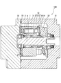
- FIG. 1 is a cross-sectional view of a piston pump to which a shoe according to an embodiment of the present invention is applied.
- FIG. 2 is a diagram showing a shoe manufacturing method according to the embodiment of the present invention in time series.
- FIG. 3 is a schematic view of a discharge plasma sintering apparatus.
- FIG. 4 is a diagram showing heat treatment conditions and pressure conditions for joining the bulk material 30 and the bulk material 31.
- FIG. 5A is a scanning electron micrograph of the bonding interface between the bulk material 30 and the bulk material 31 in the first embodiment.
- FIG. 5B is a scanning electron micrograph of the bonding interface between the bulk material 30 and the bulk material 31 in the first embodiment, and is a mapping image of FeL ⁇ by EDX analysis.
- FIG. 5A is a scanning electron micrograph of the bonding interface between the bulk material 30 and the bulk material 31 in the first embodiment.
- FIG. 5B is a scanning electron micrograph of the bonding interface between the bulk material 30 and the bulk material 31 in the first
- FIG. 5C is a scanning electron micrograph of the bonding interface between the bulk material 30 and the bulk material 31 in the first embodiment, and is a mapping image of CuL ⁇ by EDX analysis.
- FIG. 6A is a scanning electron micrograph of the bonding interface between the bulk material 30 and the bulk material 31 in the first embodiment, and is a mapping image of SiK ⁇ by EDX analysis.
- FIG. 6B is a scanning electron micrograph of the bonding interface between the bulk material 30 and the bulk material 31 in the first embodiment, and is a mapping image of AlK ⁇ by EDX analysis.
- FIG. 7A is a scanning electron micrograph of the bonding interface between the bulk material 30 and the bulk material 31 in the second embodiment.
- FIG. 7B is a scanning electron micrograph of the bonding interface between the bulk material 30 and the bulk material 31 in the second embodiment, and is a mapping image of FeL ⁇ by EDX analysis.
- FIG. 7C is a scanning electron micrograph of the bonding interface between the bulk material 30 and the bulk material 31 in the second embodiment, and is a mapping image of CuL ⁇ by EDX analysis.
- the piston pump 100 is mounted on a construction machine such as a hydraulic excavator or a hydraulic crane, for example, and supplies a working fluid (working oil) to a hydraulic cylinder or a hydraulic motor as an actuator.
- a construction machine such as a hydraulic excavator or a hydraulic crane, for example, and supplies a working fluid (working oil) to a hydraulic cylinder or a hydraulic motor as an actuator.
- the piston pump 100 includes a drive shaft 1 to which engine power is transmitted and a cylinder block 2 that rotates as the drive shaft 1 rotates.
- a plurality of cylinder bores 3 are formed in the cylinder block 2 so as to be parallel to the drive shaft 1.
- a piston 5 that defines a volume chamber 4 is inserted into the cylinder bore 3 so as to reciprocate.
- a shoe 10 is rotatably connected to the tip of the piston 5 via a spherical spherical seat 11.
- the shoe 10 includes a flat plate portion 12 formed integrally with the spherical seat 11.
- the flat plate portion 12 is in surface contact with the swash plate 20 fixed to the case 21.
- the cylinder block 2 rotates, the flat plate portion 12 of each shoe 10 comes into sliding contact with the swash plate 20, and each piston 5 reciprocates with a stroke amount corresponding to the tilt angle of the swash plate 20.
- the volume of each volume chamber 4 is increased or decreased by the reciprocation of each piston 5.
- a valve plate 23 with which the base end surface of the cylinder block 2 is in sliding contact is attached to the case 22.
- a suction port and a discharge port are formed in the valve plate 23.
- the shoe 10 connected to the tip of the piston 5 is in sliding contact with the swash plate 20. Therefore, it is necessary to reduce the frictional force between the flat plate portion 12 of the shoe 10 and the swash plate 20 in order to smoothly perform the reciprocating motion of the piston 5 and perform stable suction and discharge of the hydraulic oil. Further, when the discharge pressure of the piston pump 100 increases, the flat plate portion 12 of the shoe 10 is strongly pressed against the swash plate 20, so that the frictional force between the flat plate portion 12 and the swash plate 20 increases. Therefore, in order to increase the pressure of the piston pump 100, it is necessary to improve the slidability of the flat plate portion 12.
- the shoe 10 includes the main body portion 13 including the spherical seat 11 and the flat plate portion 12, and the sliding portion 14 that is in sliding contact with the swash plate 20.
- an iron-based metal bulk material 30 that functions as the main body portion 13 and a Cu alloy bulk material 31 that functions as the sliding portion 14 are used.
- the bulk material 30 and the bulk material 31 are cylindrical members having the same diameter as that of the shoe 10.
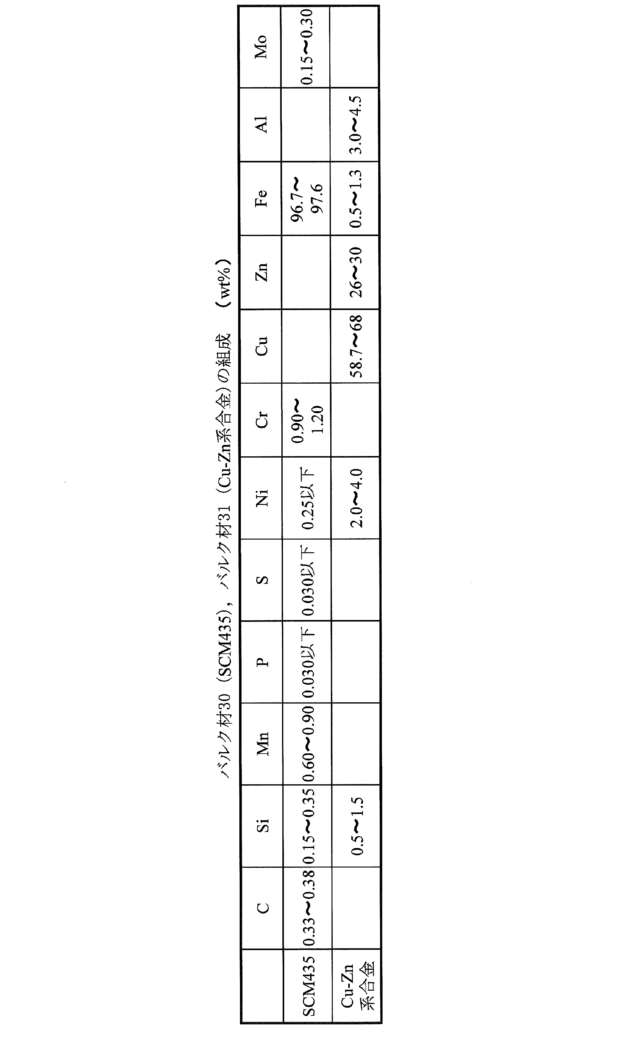
- SCM435 (JIS) of Cr—Mo steel is used as the iron-based metal of the bulk material 30.
- a Cu—Zn alloy is used as the Cu alloy of the bulk material 31.
- Cu alloy refers to an alloy mainly composed of copper.
- the Cu—Zn-based alloy refers to an alloy containing copper as a main component and containing zinc. Specifically, zinc is desirably 35 wt% or less in order to suppress formation of a brittle CuZn phase.
- Table 1 shows the composition of the bulk material 30 (SCM435) and the bulk material 31 (Cu—Zn alloy).
- the bulk material 30 is cut to a desired thickness. Specifically, it is cut into a dimension corresponding to the axial length of the main body 13.
- the bulk material 31 is also cut to a desired thickness. Specifically, it is cut into a dimension corresponding to the thickness of the sliding portion 14.
- the bulk material 30 and the bulk material 31 cut to a desired thickness in the first step have their end faces formed by heating and pressing by a spark plasma sintering method (SPS (Spark Plasma Sintering) method).
- SPS Spark Plasma Sintering
- the discharge plasma sintering method is a sintering method in which a pulsed large current is applied to the gap between the objects to be joined and the heat and electric field diffusion are promoted by the discharge plasma generated instantaneously.
- the discharge plasma sintering apparatus 40 in which the discharge plasma sintering method of a 2nd process is performed is demonstrated.
- the discharge plasma sintering apparatus 40 includes a cylindrical jig 48 made of high-strength WC in which the members to be joined are accommodated, and an upper punch 41a and a lower punch 41b for holding the members to be joined and holding them in the jig 48.
- An upper electrode 42a and a lower electrode 42b that are arranged in contact with the upper punch 41a and the lower punch 41b to apply a current to the member to be joined, and a power source 43 connected to the upper electrode 42a and the lower electrode 42b.
- the jig 48 is disposed in the vacuum chamber 46, and the joined members are joined in a vacuum atmosphere.
- a through hole penetrating the inner and outer peripheral surfaces is formed in the body portion of the jig 48, and a thermocouple 47 is inserted into the through hole. Since the thermocouple 47 is arranged so that the tip thereof is positioned in the vicinity of the bonding surface of the member to be bonded, the temperature of the bonding surface of the member to be bonded can be measured.
- the measurement result by the thermocouple 47 is transmitted to the control device 45, and the control device 45 turns the power source 43 on the basis of the measurement result so that the temperature of the joining surface of the member to be joined and the rate of temperature increase become a predetermined set value. Control.
- a method for joining the bulk material 30 and the bulk material 31 that are the members to be joined will be specifically described.
- the bulk material 30 and the bulk material 31 are accommodated in the hollow portion of the jig 48 and are sandwiched between the upper punch 41a and the lower punch 41b. Thereby, the bulk material 30 and the bulk material 31 are accommodated in the jig 48 in a state in which the end surfaces of the bulk material 30 and the bulk material 31 are stacked.
- a current is applied to the bulk material 30 and the bulk material 31 through a power source 43, and the temperature is raised to a predetermined temperature at a predetermined temperature increase rate.
- the predetermined temperature that is, the bonding temperature
- the predetermined temperature is set to be equal to or lower than the melting point of the bulk material 30 (SCM435) and the bulk material 31 (Cu—Zn alloy).
- a predetermined pressing force is applied to the bulk material 30 and the bulk material 31 through the upper punch 41a and the lower punch 41b by the pressurizing mechanism 44, and the state is maintained for a certain period of time.
- the bulk material 30 and the bulk material 31 are heat-pressed in a state where the end surfaces of the bulk material 30 and the bulk material 31 are in close contact with each other, and discharge plasma is generated at the bonding interface to cause a solid-phase reaction to be bonded.
- the bulk material 30 and the bulk material 31 are compressed and deformed by being pressurized, and the thickness is reduced by about 5%.
- the solid line indicates temperature
- the dotted line indicates pressure.
- the temperature was raised to 600 ° C. in 2 minutes
- the temperature was raised from 600 ° C. to 730 ° C. in 1 minute
- the temperature was raised from 730 ° C. to the bonding temperature of 750 ° C. in 1 minute, and held at 750 ° C. for 3 minutes, Then naturally cool.
- pressurization starts at the same time as the temperature rise, maintains a pressure of 20 MPa, and releases at the same time as natural cooling.
- the time required for joining is 7 minutes in total, and joining is completed in a short time.
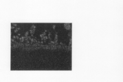
- FIGS. 5A to 5C scanning electron micrographs of the bonding interface between the bulk material 30 and the bulk material 31 bonded under the heat treatment conditions and pressure conditions shown in FIG. 4 are shown in FIGS. 5A to 5C.
- 5A is a secondary electron image
- FIG. 5B is a mapping image of FeL ⁇ by EDX analysis
- FIG. 5C is a mapping image of CuL ⁇ by EDX analysis.
- 5A to 5C the upper side of the photograph is SCM435, and the lower side of the photograph is a Cu—Zn alloy.
- SCM435 diffused to the Cu—Zn alloy side, and formation of a columnar structure in which SCM435 and the Cu—Zn alloy were skewered across the initial bonding interface was confirmed.
- This columnar structure can be said to indicate solid phase diffusion bonding between SCM435 and a Cu—Zn alloy.
- FIG. 5B and FIG. 5C it was confirmed that atomic interdiffusion occurred mutually across the junction interface.
- the constituent elements of SCM435 and Cu—Zn alloys and Fe or Cu which is the main element of the counterpart alloy in which the constituent elements diffuse
- the constituent elements of SCM435 and Cu—Zn alloys are both Whether to form a concentration gradient between the alloys was examined based on the equilibrium diagram.
- the solid solubility limit of Si, which is a constituent element of both the SCM435 and Cu—Zn alloy, in Cu is 9.95 at% at 552 ° C.
- the solid solubility limit of Si in Fe is 1200. It is 29.8 at% at ° C. Therefore, Si can be expected to diffuse from the Cu—Zn-based alloy to SCM435, and may form a concentration gradient.
- the solid solubility limit of Al which is a constituent element of the Cu—Zn alloy, in Fe is 55.0 at% at the eutectic temperature of 1102 ° C.
- the solid solubility limit of Al in Cu is 567 ° C. 19.7 at%. Therefore, Al can be expected to diffuse from the Cu—Zn-based alloy into the SCM 435, and may form a concentration gradient.
- FIG. 6A and 6B show scanning electron micrographs of the bonding interface between the bulk material 30 and the bulk material 31.
- FIG. 6A is a mapping image of SiK ⁇ by EDX analysis
- FIG. 6B is a mapping image of AlK ⁇ by EDX analysis.
- the upper side of the photograph is SCM435 and the lower side of the photograph is a Cu—Zn alloy.
- Si shows a strong concentration gradient.
- Al shows a concentration gradient though not as much as Si. From the above, it is considered that the Cu—Zn alloy containing Si and Al promoted the diffusion of Fe atoms to the Cu—Zn alloy side. That is, it is considered that the inclusion of at least one of Al and Si as the Cu—Zn-based alloy promotes the formation of the columnar structure.
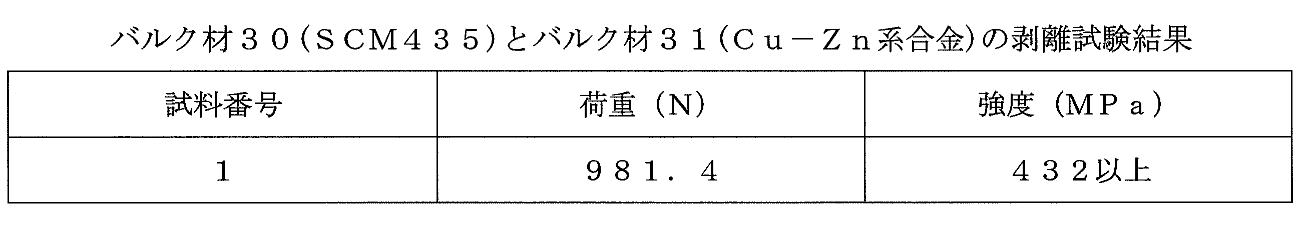
- the bonding strength between the bulk material 30 and the bulk material 31 was evaluated by a peeling test in which the bonded bulk material 30 and the bulk material 31 were pulled in opposite directions and measured for peeling strength.
- Table 2 shows the peel test results
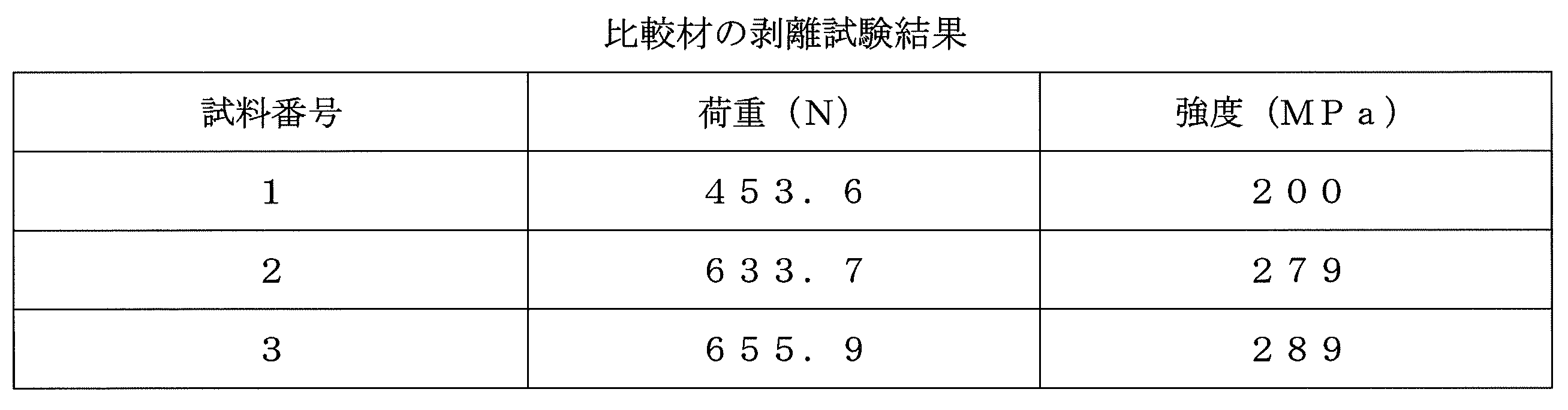
- Table 3 shows the peel test results of the comparative materials.
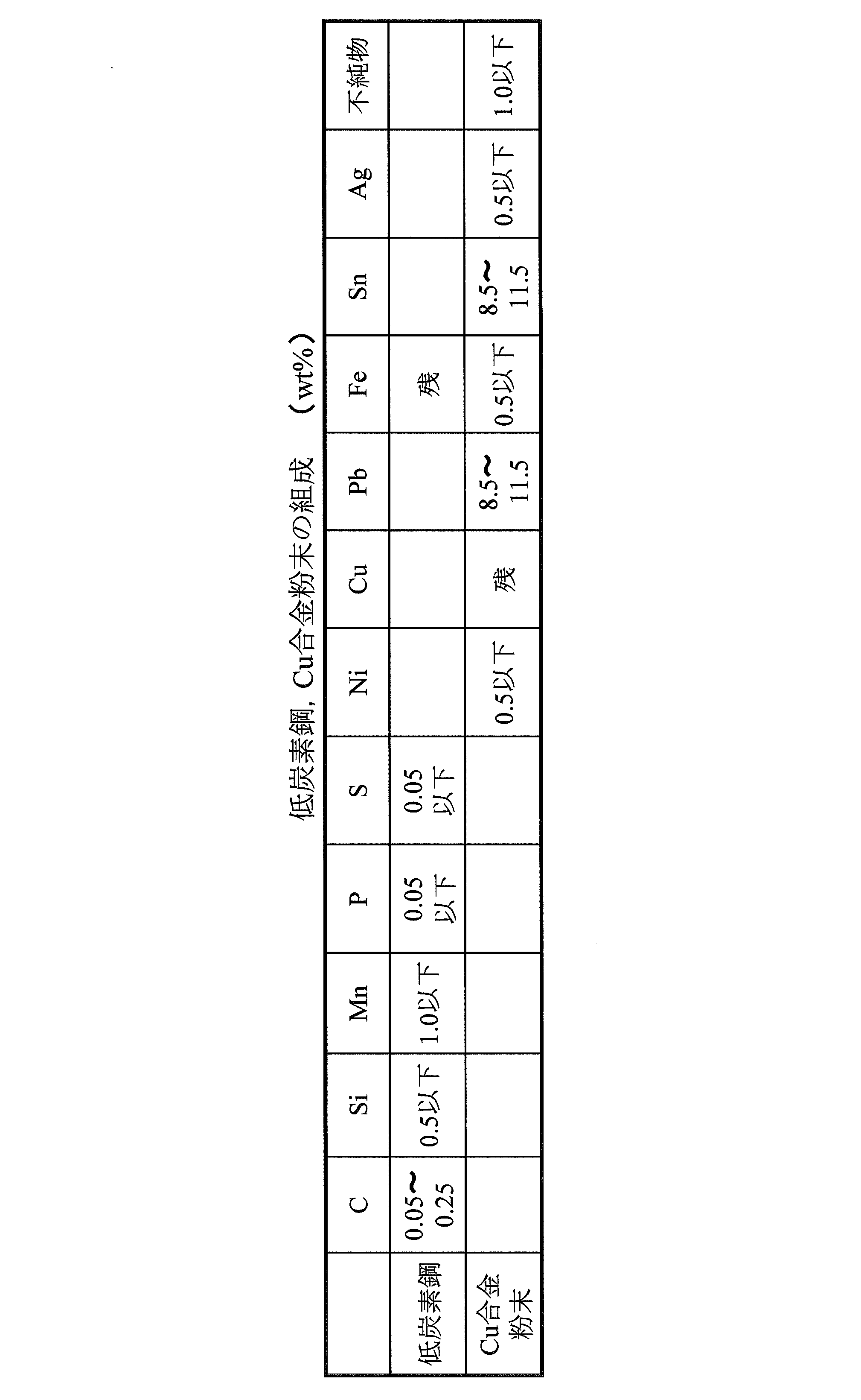
- the comparative material is obtained by a conventional manufacturing method, and is obtained by joining a low carbon steel and a Cu alloy by sintering Cu alloy powder on a copper underlayer plated on the low carbon steel.
- Table 4 shows the compositions of the low-carbon steel and Cu alloy powder as comparative materials.
- the bonding strength between the bulk material 30 and the bulk material 31 is greater than that of the comparative material. In this way, by joining SCM435 and Cu—Zn-based alloy by the discharge plasma sintering method, both can be joined directly, and can be joined via a columnar structure. High bonding strength can be obtained as compared with the conventional bonding.
- the bulk material 30 and the bulk material 31 are firmly joined to obtain the material 32 that is the basis of the shoe 10.
- the material 32 is processed into a desired shape. Specifically, the bulk material 30 of the material 32 is cut into the shape of the spherical seat 11 and the flat plate portion 12. Further, the bulk material 31 is formed with a sliding portion 14 by cutting a circular groove 31 a at the end face. Finally, a through hole (not shown) that passes through the spherical seat 11, the flat plate portion 12, and the sliding portion 14 in the axial direction is cut. This through hole is for guiding the hydraulic oil inside the piston 5 to the groove 31 a and reducing the surface pressure of the sliding portion 14 and the swash plate 20.
- the groove 31a is not an essential configuration and may be omitted.
- the waste material in the processing of the material 32 is SCM 435 which is mainly cut into the shape of the spherical seat 11 and the flat plate portion 12, and most of the Cu—Zn-based alloy which is expensive compared to the SCM 435 is waste material.
- SCM 435 which is mainly cut into the shape of the spherical seat 11 and the flat plate portion 12
- most of the Cu—Zn-based alloy which is expensive compared to the SCM 435 is waste material.
- the entire shoe 10 is manufactured from a Cu—Zn alloy, a large amount of the Cu—Zn alloy becomes a waste material when it is cut into the shape of the spherical seat 11 and the flat plate portion 12.
- the amount of waste material of the Cu—Zn alloy can be reduced, and the manufacturing cost can be reduced. be able to.
- nitriding is performed on the material 32 processed in the third step.
- gas soft nitriding is performed.
- the gas soft nitriding treatment is performed in a mixed gas atmosphere of carburizing gas (RX gas) and ammonia gas (NH 3 gas) mainly composed of carbon monoxide (CO) at a temperature of 570 ° C. for 2.5 hours.
- RX gas carburizing gas
- NH 3 gas ammonia gas
- CO carbon monoxide
- SCM435 and Cu—Zn alloy can be directly solid-phase bonded without using a binder such as plating.
- the main body 13 that is pivotally connected to the tip of the piston 5 and that requires strength is formed of the SCM 435, and the sliding portion 14 that is in sliding contact with the swash plate 20 and requires slidability is made of a Cu—Zn alloy.
- a highly functional bimetal shoe 10 combining the advantages of SCM435 and Cu—Zn alloy can be obtained.
- the bulk material 30 of the SCM 435 and the bulk material 31 of the Cu—Zn alloy can be easily joined with high joint strength by using the heating and pressurization by the discharge plasma sintering method. .
- the Cu alloy of the bulk material 31 is a Cu—Zn alloy.
- the Cu alloy of the present invention is not limited to a Cu—Zn alloy. Therefore, in the second embodiment, a case where the Cu alloy of the bulk material 31 is a Cu—Ni alloy will be described.
- the Cu—Ni alloy is an alloy containing copper as a main component and nickel. However, considering that the solid solution hardening becomes too large when nickel is contained in a large amount and that nickel is expensive, the nickel content is desirably 10 wt% or more and 30 wt% or less.
- Table 5 shows the composition of the bulk material 31 (Cu—Ni alloy). Sn is added for the purpose of improving the friction resistance of the sliding portion 14.
- the composition of the bulk material 30 (SCM435) is as shown in Table 1.
- the manufacturing method of the shoe 10 is the same as the process shown in FIG.
- FIGS. 7A to 7C Scanning electron micrographs of the bonding interface between the bulk material 30 and the bulk material 31 bonded under the heat treatment condition and the pressure condition shown in FIG. 4 are shown in FIGS. 7A to 7C.
- 7A is a secondary electron image
- FIG. 7B is a mapping image of FeL ⁇ by EDX analysis
- FIG. 7C is a mapping image of CuL ⁇ by EDX analysis.
- 7A to 7C the upper side of the photograph is SCM435 and the lower side of the photograph is a Cu—Ni-based alloy. Even in the combination of the bulk material 30 of SCM435 and the bulk material 31 of the Cu—Ni alloy, both are directly applied by generating a discharge plasma at the bonding interface and causing a solid phase reaction while applying pressure. Can be joined.
- the bonding strength between the bulk material 30 and the bulk material 31 was evaluated by a peeling test in which the bonded bulk material 30 and the bulk material 31 were pulled in opposite directions and measured for peeling strength.
- Table 6 shows the peel test results.
- the bonding strength of the bulk material 30 and the bulk material 31 is equivalent to the bonding strength of the comparative material shown in Table 3.
- a high joint strength equivalent to that of the conventional one can be obtained, although it is not jointed via the columnar structure.
- SCM435 and Cu—Ni alloy can also be directly solid-phase bonded without using a binder such as plating by using heating and pressurizing by the discharge plasma sintering method. it can.
- the bulk material of the iron-based metal and the bulk material of the Cu alloy are high in bonding strength. And it can join simply.
- the method for manufacturing the shoe 10 of the swash plate type piston pump has been described.
- the method can be naturally applied to the method of manufacturing the shoe of the swash plate type piston motor.
- the sliding member of the present invention is the shoe 10 of the swash plate type piston pump motor
- the sliding member is not limited to this, and may be a sliding bearing that supports the shaft.
- the sliding portion that is in sliding contact with the shaft may be made of a Cu alloy, and the other main body portion may be made of an iron-based metal.
- the sliding member manufactured by the manufacturing method of the present invention can be applied to a shoe of a piston pump motor.
Landscapes
- Engineering & Computer Science (AREA)
- Chemical & Material Sciences (AREA)
- Mechanical Engineering (AREA)
- Materials Engineering (AREA)
- Organic Chemistry (AREA)
- Metallurgy (AREA)
- Manufacturing & Machinery (AREA)
- General Engineering & Computer Science (AREA)
- Physics & Mathematics (AREA)
- Composite Materials (AREA)
- Optics & Photonics (AREA)
- Plasma & Fusion (AREA)
- Reciprocating Pumps (AREA)
- Pressure Welding/Diffusion-Bonding (AREA)
- Powder Metallurgy (AREA)
- Details Of Reciprocating Pumps (AREA)
Abstract
Description
以下では、摺動部材が斜板型ピストンポンプのシューである場合について説明する。まず、図1を参照して、ピストンポンプ100について説明する。
以下の第2実施形態の説明では、上記第1実施形態と異なる点を中心に説明し、上記第1実施形態と同一の構成には同一の符号を付して説明を省略する。


Claims (4)
- 摺動部を有する摺動部材の製造方法であって、
前記摺動部材の本体部として機能する鉄系金属のバルク材と前記摺動部として機能するCu合金のバルク材とを放電プラズマ焼結法による加熱加圧によって固相接合して摺動部材を製造する摺動部材の製造方法。 - 請求項1に記載の摺動部材の製造方法であって、
前記Cu合金は、Cu-Zn系合金であり、
前記鉄系金属のバルク材と前記Cu合金のバルク材とは、柱状組織を介して接合される摺動部材の製造方法。 - 請求項2に記載の摺動部材の製造方法であって、
前記Cu合金は、Al及びSiの少なくとも一方を含む摺動部材の製造方法。 - 請求項1に記載の摺動部材の製造方法であって、
前記摺動部材は、ピストンポンプモータにおいてピストンの先端に回動自在に連結されると共に斜板に摺接するシューであり、
前記鉄系金属は、前記ピストンの先端に回動自在に連結される本体部として機能し、
前記Cu合金は、前記斜板に摺接する摺動部として機能する摺動部材の製造方法。
Priority Applications (4)
| Application Number | Priority Date | Filing Date | Title |
|---|---|---|---|
| KR20137025466A KR20140010101A (ko) | 2011-03-02 | 2012-02-22 | 미끄럼 이동 부재의 제조 방법 |
| CN2012800110852A CN103402690A (zh) | 2011-03-02 | 2012-02-22 | 滑动构件的制造方法 |
| EP12752662.2A EP2682217B1 (en) | 2011-03-02 | 2012-02-22 | Method for fabricating slidable member |
| US14/002,655 US20130333200A1 (en) | 2011-03-02 | 2012-02-22 | Sliding member manufacturing method |
Applications Claiming Priority (2)
| Application Number | Priority Date | Filing Date | Title |
|---|---|---|---|
| JP2011-045554 | 2011-03-02 | ||
| JP2011045554A JP5706193B2 (ja) | 2011-03-02 | 2011-03-02 | 摺動部材の製造方法 |
Publications (1)
| Publication Number | Publication Date |
|---|---|
| WO2012117908A1 true WO2012117908A1 (ja) | 2012-09-07 |
Family
ID=46757847
Family Applications (1)
| Application Number | Title | Priority Date | Filing Date |
|---|---|---|---|
| PCT/JP2012/054219 WO2012117908A1 (ja) | 2011-03-02 | 2012-02-22 | 摺動部材の製造方法 |
Country Status (7)
| Country | Link |
|---|---|
| US (1) | US20130333200A1 (ja) |
| EP (1) | EP2682217B1 (ja) |
| JP (1) | JP5706193B2 (ja) |
| KR (1) | KR20140010101A (ja) |
| CN (1) | CN103402690A (ja) |
| TW (1) | TWI554352B (ja) |
| WO (1) | WO2012117908A1 (ja) |
Cited By (2)
| Publication number | Priority date | Publication date | Assignee | Title |
|---|---|---|---|---|
| WO2014042161A1 (ja) * | 2012-09-12 | 2014-03-20 | 株式会社タカコ | 摺動部材の製造方法 |
| CN104400339A (zh) * | 2014-10-28 | 2015-03-11 | 东莞市中一合金科技有限公司 | 连续条复焊料带材加工工艺及焊料带材 |
Families Citing this family (6)
| Publication number | Priority date | Publication date | Assignee | Title |
|---|---|---|---|---|
| US10384301B2 (en) | 2013-10-16 | 2019-08-20 | Komatsu Ltd. | Sliding component, method for producing sliding component, and device for producing sliding component |
| CN104014921B (zh) * | 2014-04-25 | 2016-04-27 | 长安大学 | 一种快速制备铜钼多层复合材料的方法 |
| JP5939590B2 (ja) * | 2014-06-30 | 2016-06-22 | 株式会社日本製鋼所 | 高硬度高熱伝導性複合金属材、高硬度高熱伝導性複合金属材の製造方法およびプラスチックまたは繊維強化プラスチック成形用金型 |
| DE112015006451T5 (de) | 2015-04-15 | 2018-01-18 | Komatsu Ltd. | Gleitendes Bauteil und Verfahren zum Herstellen desselben |
| KR101814665B1 (ko) * | 2016-07-26 | 2018-01-04 | 주식회사대영금속 | 방전 플라즈마를 이용한 이종복합소재의 제조 및 접합방법 |
| CN112091211B (zh) * | 2020-08-20 | 2021-09-10 | 上海交通大学 | 一种扩散多元节的制备方法 |
Citations (8)
| Publication number | Priority date | Publication date | Assignee | Title |
|---|---|---|---|---|
| JPH05156388A (ja) * | 1991-12-03 | 1993-06-22 | Oiles Ind Co Ltd | 複層焼結摺動部材ならびにその製造方法 |
| JPH10196552A (ja) * | 1997-01-16 | 1998-07-31 | Komatsu Ltd | 焼結接合シリンダブロック |
| JP2000230476A (ja) * | 1999-02-08 | 2000-08-22 | Hitachi Constr Mach Co Ltd | 斜板式液圧回転機 |
| JP2003112264A (ja) * | 2001-09-28 | 2003-04-15 | Sumitomo Coal Mining Co Ltd | 小接合面用パルス通電接合方法、接合装置及び接合体 |
| JP2005257035A (ja) | 2004-03-15 | 2005-09-22 | Kayaba Ind Co Ltd | 多層軸受材料 |
| JP2007253240A (ja) * | 2007-05-14 | 2007-10-04 | Sps Syntex Inc | 小接合面用パルス通電接合装置 |
| JP2008121095A (ja) * | 2006-11-15 | 2008-05-29 | Hitachi Powdered Metals Co Ltd | 複合焼結機械部品の製造方法およびシリンダブロック |
| JP2012024833A (ja) * | 2010-07-27 | 2012-02-09 | Japan Aerospace Exploration Agency | パルス通電接合方法及びパルス通電接合装置 |
Family Cites Families (15)
| Publication number | Priority date | Publication date | Assignee | Title |
|---|---|---|---|---|
| EP0389625A1 (en) * | 1988-02-29 | 1990-10-03 | Kabushiki Kaisha Komatsu Seisakusho | Process for resistance diffusion junction |
| JPH0677829B2 (ja) * | 1988-08-19 | 1994-10-05 | 株式会社小松製作所 | 摺動部品の製造方法 |
| DE4411762A1 (de) * | 1994-04-06 | 1995-10-12 | Kolbenschmidt Ag | Gleitlagerwerkstoff |
| JP4100583B2 (ja) * | 1997-08-25 | 2008-06-11 | 中越合金鋳工株式会社 | 鉄系材料と高力黄銅合金を接合する方法 |
| JPH11158514A (ja) * | 1997-11-25 | 1999-06-15 | Matsushita Electric Works Ltd | 金属バルク材の接合方法及び金属バルク材の接合体 |
| JP3548509B2 (ja) * | 2000-06-07 | 2004-07-28 | 諏訪熱工業株式会社 | パルス通電接合方法及び接合装置並びに接合体 |
| JP3857535B2 (ja) * | 2001-03-21 | 2006-12-13 | 独立行政法人科学技術振興機構 | 非晶質合金材料のパルス通電接合方法 |
| JP4301761B2 (ja) * | 2002-03-08 | 2009-07-22 | 昌雄 本藤 | パルス通電による接合装置 |
| JP3737989B2 (ja) * | 2002-05-17 | 2006-01-25 | 昌雄 本藤 | パルス通電による部材の接合方法 |
| EP1508693B1 (en) * | 2003-08-18 | 2015-08-12 | Senju Metal Industry Co., Ltd. | Multi layer sliding part and a method for its manufacture |
| CN100415910C (zh) * | 2006-09-08 | 2008-09-03 | 北京科技大学 | 用放电等离子烧结技术制备储氢合金的方法 |
| FR2906242B1 (fr) * | 2006-09-27 | 2009-01-16 | Commissariat Energie Atomique | Procede d'assemblage de pieces en ceramique refractaire par frittage a chaud avec champ electrique pulse ("sps") |
| JP5132685B2 (ja) * | 2007-11-08 | 2013-01-30 | 相田化学工業株式会社 | 金属熱成形体、その製造方法、及び模様金属板材の製造方法 |
| CN201374833Y (zh) * | 2009-03-02 | 2009-12-30 | 深圳大学 | 一种复合电极压头及放电等离子烧结设备 |
| CN101733623B (zh) * | 2009-12-10 | 2012-05-09 | 北京科技大学 | 一种金属层状复合材料放电等离子体制备方法 |
-
2011
- 2011-03-02 JP JP2011045554A patent/JP5706193B2/ja active Active
-
2012
- 2012-02-22 US US14/002,655 patent/US20130333200A1/en not_active Abandoned
- 2012-02-22 KR KR20137025466A patent/KR20140010101A/ko not_active Application Discontinuation
- 2012-02-22 CN CN2012800110852A patent/CN103402690A/zh active Pending
- 2012-02-22 EP EP12752662.2A patent/EP2682217B1/en active Active
- 2012-02-22 WO PCT/JP2012/054219 patent/WO2012117908A1/ja active Application Filing
- 2012-03-01 TW TW101106628A patent/TWI554352B/zh active
Patent Citations (8)
| Publication number | Priority date | Publication date | Assignee | Title |
|---|---|---|---|---|
| JPH05156388A (ja) * | 1991-12-03 | 1993-06-22 | Oiles Ind Co Ltd | 複層焼結摺動部材ならびにその製造方法 |
| JPH10196552A (ja) * | 1997-01-16 | 1998-07-31 | Komatsu Ltd | 焼結接合シリンダブロック |
| JP2000230476A (ja) * | 1999-02-08 | 2000-08-22 | Hitachi Constr Mach Co Ltd | 斜板式液圧回転機 |
| JP2003112264A (ja) * | 2001-09-28 | 2003-04-15 | Sumitomo Coal Mining Co Ltd | 小接合面用パルス通電接合方法、接合装置及び接合体 |
| JP2005257035A (ja) | 2004-03-15 | 2005-09-22 | Kayaba Ind Co Ltd | 多層軸受材料 |
| JP2008121095A (ja) * | 2006-11-15 | 2008-05-29 | Hitachi Powdered Metals Co Ltd | 複合焼結機械部品の製造方法およびシリンダブロック |
| JP2007253240A (ja) * | 2007-05-14 | 2007-10-04 | Sps Syntex Inc | 小接合面用パルス通電接合装置 |
| JP2012024833A (ja) * | 2010-07-27 | 2012-02-09 | Japan Aerospace Exploration Agency | パルス通電接合方法及びパルス通電接合装置 |
Non-Patent Citations (1)
| Title |
|---|
| See also references of EP2682217A4 |
Cited By (3)
| Publication number | Priority date | Publication date | Assignee | Title |
|---|---|---|---|---|
| WO2014042161A1 (ja) * | 2012-09-12 | 2014-03-20 | 株式会社タカコ | 摺動部材の製造方法 |
| JP2014055554A (ja) * | 2012-09-12 | 2014-03-27 | Takako:Kk | 摺動部材の製造方法 |
| CN104400339A (zh) * | 2014-10-28 | 2015-03-11 | 东莞市中一合金科技有限公司 | 连续条复焊料带材加工工艺及焊料带材 |
Also Published As
| Publication number | Publication date |
|---|---|
| KR20140010101A (ko) | 2014-01-23 |
| TWI554352B (zh) | 2016-10-21 |
| TW201300185A (zh) | 2013-01-01 |
| CN103402690A (zh) | 2013-11-20 |
| EP2682217A1 (en) | 2014-01-08 |
| JP2012179649A (ja) | 2012-09-20 |
| EP2682217A4 (en) | 2015-06-03 |
| EP2682217B1 (en) | 2017-05-10 |
| JP5706193B2 (ja) | 2015-04-22 |
| US20130333200A1 (en) | 2013-12-19 |
Similar Documents
| Publication | Publication Date | Title |
|---|---|---|
| WO2012117908A1 (ja) | 摺動部材の製造方法 | |
| KR100987556B1 (ko) | 소결 복합체 기계 부품 및 그의 제조 방법 | |
| US8361939B2 (en) | Multilayered sintered sliding member | |
| WO2012147780A1 (ja) | 摺動材料、軸受用合金及び軸受用複層金属材 | |
| KR20180075535A (ko) | 스퍼터링 타깃의 제조 방법 및 스퍼터링 타깃 | |
| JP5386373B2 (ja) | 焼結銅合金摺動材の製造方法及び焼結銅合金摺動材 | |
| JP6027825B2 (ja) | 摺動部材の製造方法 | |
| JP2010215951A (ja) | 焼結複合摺動部品およびその製造方法 | |
| Kundu et al. | Interfacial reaction and microstructure study of DSS/Cu/Ti64 diffusion-welded couple | |
| JP5981868B2 (ja) | 摺動部材およびすべり軸受 | |
| JP2015121328A (ja) | 摺動部材の製造方法 | |
| JP6190804B2 (ja) | ピストンポンプ・モータ | |
| CN113118716B (zh) | 一种高结合强度铜钢双金属减摩耐磨复合材料的焊接方法 | |
| KR20110118283A (ko) | 무급유 방청 소결 베어링 | |
| JP4383837B2 (ja) | 金属基複合材料の製造方法及びその方法で製造された複合材料 | |
| JPH07256445A (ja) | 銅合金のライニング方法 | |
| JP5953103B2 (ja) | 摺動材料の製造方法 | |
| JP5562463B1 (ja) | スラスト軸受 | |
| JP4446073B2 (ja) | チタンアルミ金属間化合物と銅合金との接合法 | |
| EP2957649A1 (en) | Sliding member and production method for sliding member | |
| JP2013136078A (ja) | 複合ろう材とそれを用いたろう付方法及びその接合した鉄鋼製品 | |
| KR20020054938A (ko) | 피스톤식 유압펌프의 피스톤 슈 제조방법 |
Legal Events
| Date | Code | Title | Description |
|---|---|---|---|
| 121 | Ep: the epo has been informed by wipo that ep was designated in this application |
Ref document number: 12752662 Country of ref document: EP Kind code of ref document: A1 |
|
| WWE | Wipo information: entry into national phase |
Ref document number: 14002655 Country of ref document: US |
|
| NENP | Non-entry into the national phase |
Ref country code: DE |
|
| ENP | Entry into the national phase |
Ref document number: 20137025466 Country of ref document: KR Kind code of ref document: A |
|
| REEP | Request for entry into the european phase |
Ref document number: 2012752662 Country of ref document: EP |
|
| WWE | Wipo information: entry into national phase |
Ref document number: 2012752662 Country of ref document: EP |