WO2012117760A1 - 車両用内装部品 - Google Patents
車両用内装部品 Download PDFInfo
- Publication number
- WO2012117760A1 WO2012117760A1 PCT/JP2012/051054 JP2012051054W WO2012117760A1 WO 2012117760 A1 WO2012117760 A1 WO 2012117760A1 JP 2012051054 W JP2012051054 W JP 2012051054W WO 2012117760 A1 WO2012117760 A1 WO 2012117760A1
- Authority
- WO
- WIPO (PCT)
- Prior art keywords
- opening
- interior
- interior part
- vehicle
- door
- Prior art date
- Legal status (The legal status is an assumption and is not a legal conclusion. Google has not performed a legal analysis and makes no representation as to the accuracy of the status listed.)
- Ceased
Links
Images





Classifications
-
- B—PERFORMING OPERATIONS; TRANSPORTING
- B60—VEHICLES IN GENERAL
- B60R—VEHICLES, VEHICLE FITTINGS, OR VEHICLE PARTS, NOT OTHERWISE PROVIDED FOR
- B60R13/00—Elements for body-finishing, identifying, or decorating; Arrangements or adaptations for advertising purposes
- B60R13/02—Internal Trim mouldings ; Internal Ledges; Wall liners for passenger compartments; Roof liners
-
- B—PERFORMING OPERATIONS; TRANSPORTING
- B60—VEHICLES IN GENERAL
- B60R—VEHICLES, VEHICLE FITTINGS, OR VEHICLE PARTS, NOT OTHERWISE PROVIDED FOR
- B60R13/00—Elements for body-finishing, identifying, or decorating; Arrangements or adaptations for advertising purposes
- B60R13/02—Internal Trim mouldings ; Internal Ledges; Wall liners for passenger compartments; Roof liners
- B60R13/0237—Side or rear panels
- B60R13/0243—Doors
-
- B—PERFORMING OPERATIONS; TRANSPORTING
- B60—VEHICLES IN GENERAL
- B60N—SEATS SPECIALLY ADAPTED FOR VEHICLES; VEHICLE PASSENGER ACCOMMODATION NOT OTHERWISE PROVIDED FOR
- B60N2/00—Seats specially adapted for vehicles; Arrangement or mounting of seats in vehicles
- B60N2/75—Arm-rests
- B60N2/78—Arm-rests post or panel mounted
- B60N2/783—Arm-rests post or panel mounted sill suspended, e.g. window sill
Definitions
- the present invention relates to a vehicle interior part provided in a passenger compartment.
- Patent Document 1 An interior part for a vehicle attached to an armrest of a door is known as disclosed in Patent Document 1.
- This interior part is a pocket for a container, and is inserted through an opening of a door lining which is an interior of a vehicle compartment, and an edge is engaged with the opening. Further, since the lower part of the interior part is fastened to the door lining with a screw member, the number of parts can be reduced, and the interior part can be attached without taking time and effort.
- Patent Document 1 may inadvertently drop the screw member when the screw member is fastened to the lower part with a tool. When the dropped screw member falls into the door, it takes time to take out the screw member from the door.
- the screw part used for fastening to the fixed part, and the fastening opened to pass the screw part
- an interior part for a vehicle including a hole, a tray part formed below the fastening hole, and an opening formed in the tray part so as not to pass the screw part.
- the opening preferably comprises a plurality of openings.
- the screw part when the interior part is assembled with the screw part, the screw part can be inadvertently received by the tray even if the screw part is dropped from the tool or the fastening hole, and the screw part can be prevented from falling. it can.
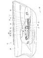
- FIG. 4 is a perspective view of the interior part shown in FIG. 3.
- FIG. 5 is a cross-sectional view taken along line 5-5 of FIG.
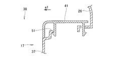
- FIG. 6 is a cross-sectional view taken along line 6-6 in FIG.
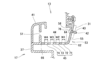
- FIG. 7 is a cross-sectional view taken along line 7-7 in FIG.
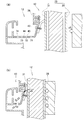
- It is sectional drawing which showed the state which attaches an interior component to an inner panel with a screw component. It is sectional drawing which showed the state which discharges water from the interior component shown in FIG. It is the figure which showed the state which an interior component absorbs an impact, (a) is sectional drawing which showed the state before an impact load is input, (b) is the cross section which showed the state after input FIG.
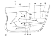
- the door 12 is a right front door and includes a door opening lever 16, an armrest 17, and an operation panel 21 disposed on the armrest 17. On the operation panel 21, buttons for opening and closing the glass 22 of the right front door 12 and the door glass of the left front door (not shown) are arranged.
- the door 12 includes a storage box that is an interior part 13 disposed on the armrest 17 and a speaker placement portion 24.
- a door interior wall 26 is attached to the door body 25.
- the door body 25 includes an outer panel 28 and an inner panel 31.
- the door interior wall 26, the interior part 13, and the armrest 17 are fixed to the inner panel 31.
- the armrest 17 projects from the door interior wall 26 (in the direction of arrow a1 in FIG. 6) and has an armrest main body portion 32 formed to hang the elbow.
- an interior part (container box) 13 is connected to the armrest main body 32 so that the opening 34 faces upward of the vehicle body 11, and the operation panel 21 connects the button 35 to the vehicle body 11. 11 is arranged upward.
- the armrest 17 extends in the front-rear direction of the vehicle body 11.
- the base box portion 37 of the armrest 17 on which the interior part 13 and the operation panel 21 are placed projects from the door interior wall 26 toward the vehicle compartment 38 as indicated by an arrow a ⁇ b> 1.
- the cover member 41 is attached to the base box portion 37. The state where the cover member 41 and the operation panel 21 are removed is shown in FIGS.
- the cover member 41 is a cover for the operation panel 21 and a cover for the interior part 13.
- the interior part 13 is attached to an inner panel 31 that is a fixed part of the door 12.
- the interior part 13 has a fastening hole 43 formed to allow the screw part 42 to pass therethrough.
- the screw part 42 is used for fastening the interior part 13 to the inner panel 31.
- a tray portion 44 is formed below the fastening hole 43.
- the opening 45 formed in the tray portion 44 is formed in a size that does not allow the screw component 42 to pass through.
- the opening 45 is formed by a first opening 71, a second opening 72, a third opening 73, and a fourth opening 74).
- the interior part (container box) 13 has a box body 47 having a rectangular shape and a desired average depth B.
- a peripheral flange portion 48 continuous with the edge of the box body 47 is attached to the upper edge 51 (FIG. 4) of the base box portion 37.
- a fastening bracket 53 is formed on the outer side of the box body 47 continuously to the front edge flange portion 52 facing the front of the vehicle body 11 in the peripheral flange portion 48, in other words, the front edge flange portion 52 close to the operation panel 21. .
- the fastening bracket 53 includes a fastening bracket main body 55, a reinforcing bracket 56, and a tray portion 44.
- the fastening bracket main body 55 is plate-shaped and has a fastening hole 43 which is opposed to the inner panel 31 of the door 12 and is opened in an upper portion 58 located in the vicinity of the front edge flange portion 52.
- a plate-shaped reinforcing bracket 56 is connected to the edge of the fastening bracket main body 55 that is close to the box main body 47 and extends toward the vehicle compartment 38 so that the surface faces the front-rear direction of the vehicle body 11.
- a tray portion 44 is formed integrally with the lower edge 61 of the reinforcing bracket 56 and the lower edge 62 of the fastening bracket body 55.
- the tray portion 44 is plate-shaped, and the first fixed end 64 is integrally connected to the lower edge 62 of the fastening bracket body 55, and the second edge 61 is connected to the lower edge 61 of the reinforcing bracket 56 (FIG. 5).
- the fixed end 65 is integrally connected.
- An end facing the first fixed end 64 is a first free tip 66 that is not connected.
- the second free tip 67 shown in FIGS. 4 and 5 is not connected to the tip facing the second fixed end 65.
- the opening 45 formed in the tray portion 44 includes a first opening 71 formed close to the inner panel 31 of the door 12 and close to the lower side of the fastening hole 43, and the first opening.
- the second opening 72, the third opening 73, and the fourth opening 74 are formed in order in parallel with 71.
- the size (W1 to W4) of the first opening 71 to the fourth opening 74 is smaller than the head 76 of the screw part 42.
- the screw component 42 does not fall from the first opening 71 to the fourth opening 74.
- the screw component 42 when the screw component 42 is received by the tray portion 44 and rolls on the tray portion 44, the screw component 42 fits into any one of the first opening 71 to the fourth opening 74, and the screw component is removed from the tray portion 44. There is an advantage that 42 does not easily fall.
- FIG. 10 (a) when a load is applied to the door 12 from the outside, for example, a side collision impact (load) is input as shown by an arrow a5, as shown in FIG. 10 (b).
- a compression load is applied to the interior part 13 as indicated by an arrow a6.
- the load concentrates on the first opening 71 to the fourth opening 74 (FIG. 10A) of the tray portion 44, so that the tray portion 44 breaks down compared to the one without the opening 45. It is easy and can exhibit a buffer function.
- the interior part of the present invention is suitable for a vehicle door.
Landscapes
- Engineering & Computer Science (AREA)
- Mechanical Engineering (AREA)
- Aviation & Aerospace Engineering (AREA)
- Transportation (AREA)
- Vehicle Step Arrangements And Article Storage (AREA)
- Vehicle Interior And Exterior Ornaments, Soundproofing, And Insulation (AREA)
Abstract
Description
Claims (2)
- 車体側の固定部に取り付けられている車両用内装部品であって、
前記固定部への締結に用いるねじ部品と、
前記ねじ部品を通すよう開けられた締結孔と、
前記締結孔の下方に形成された受け皿部と、
前記受け皿部に前記ねじ部品が通過しない大きさに形成された開口と、
を備えていることを特徴とする車両用内装部品。 - 前記開口は、複数の開口からなる、請求項1記載の車両用内装部品。
Priority Applications (4)
| Application Number | Priority Date | Filing Date | Title |
|---|---|---|---|
| JP2013502210A JP5768125B2 (ja) | 2011-02-28 | 2012-01-19 | 車両用内装部品 |
| CN201280009915.8A CN103402800B (zh) | 2011-02-28 | 2012-01-19 | 车辆用内饰部件 |
| CA2827911A CA2827911C (en) | 2011-02-28 | 2012-01-19 | Interior part for vehicle |
| US14/000,718 US9321411B2 (en) | 2011-02-28 | 2012-01-19 | Interior part for vehicle |
Applications Claiming Priority (2)
| Application Number | Priority Date | Filing Date | Title |
|---|---|---|---|
| JP2011-041759 | 2011-02-28 | ||
| JP2011041759 | 2011-02-28 |
Publications (1)
| Publication Number | Publication Date |
|---|---|
| WO2012117760A1 true WO2012117760A1 (ja) | 2012-09-07 |
Family
ID=46757702
Family Applications (1)
| Application Number | Title | Priority Date | Filing Date |
|---|---|---|---|
| PCT/JP2012/051054 Ceased WO2012117760A1 (ja) | 2011-02-28 | 2012-01-19 | 車両用内装部品 |
Country Status (5)
| Country | Link |
|---|---|
| US (1) | US9321411B2 (ja) |
| JP (1) | JP5768125B2 (ja) |
| CN (1) | CN103402800B (ja) |
| CA (1) | CA2827911C (ja) |
| WO (1) | WO2012117760A1 (ja) |
Cited By (1)
| Publication number | Priority date | Publication date | Assignee | Title |
|---|---|---|---|---|
| JP2016060281A (ja) * | 2014-09-16 | 2016-04-25 | トヨタ紡織株式会社 | 車両用ドアトリム |
Families Citing this family (1)
| Publication number | Priority date | Publication date | Assignee | Title |
|---|---|---|---|---|
| JP6605980B2 (ja) * | 2016-02-15 | 2019-11-13 | 本田技研工業株式会社 | 車両の内装材固定構造 |
Citations (1)
| Publication number | Priority date | Publication date | Assignee | Title |
|---|---|---|---|---|
| JP2009269414A (ja) * | 2008-04-30 | 2009-11-19 | Kasai Kogyo Co Ltd | 車両用内装部品 |
Family Cites Families (5)
| Publication number | Priority date | Publication date | Assignee | Title |
|---|---|---|---|---|
| US5339676A (en) * | 1993-06-02 | 1994-08-23 | Del Johnson | Water leak detection, collection and support device |
| JPH08183406A (ja) | 1994-12-28 | 1996-07-16 | Tokyo Seat Kk | 樹脂発泡成形品に対する部品の締結固定構造 |
| US6713029B1 (en) * | 2000-09-08 | 2004-03-30 | Zimmer Technology, Inc. | Sterilization tray |
| US6899363B2 (en) * | 2003-02-19 | 2005-05-31 | Lear Corporation | Method of forming a vehicle component |
| JP4992390B2 (ja) * | 2006-11-08 | 2012-08-08 | トヨタ車体株式会社 | 車両用の収納構造 |
-
2012
- 2012-01-19 CA CA2827911A patent/CA2827911C/en active Active
- 2012-01-19 CN CN201280009915.8A patent/CN103402800B/zh not_active Expired - Fee Related
- 2012-01-19 US US14/000,718 patent/US9321411B2/en active Active
- 2012-01-19 WO PCT/JP2012/051054 patent/WO2012117760A1/ja not_active Ceased
- 2012-01-19 JP JP2013502210A patent/JP5768125B2/ja not_active Expired - Fee Related
Patent Citations (1)
| Publication number | Priority date | Publication date | Assignee | Title |
|---|---|---|---|---|
| JP2009269414A (ja) * | 2008-04-30 | 2009-11-19 | Kasai Kogyo Co Ltd | 車両用内装部品 |
Cited By (1)
| Publication number | Priority date | Publication date | Assignee | Title |
|---|---|---|---|---|
| JP2016060281A (ja) * | 2014-09-16 | 2016-04-25 | トヨタ紡織株式会社 | 車両用ドアトリム |
Also Published As
| Publication number | Publication date |
|---|---|
| JPWO2012117760A1 (ja) | 2014-07-07 |
| US9321411B2 (en) | 2016-04-26 |
| CA2827911C (en) | 2015-11-24 |
| CN103402800A (zh) | 2013-11-20 |
| US20130328338A1 (en) | 2013-12-12 |
| CA2827911A1 (en) | 2012-09-07 |
| CN103402800B (zh) | 2016-06-22 |
| JP5768125B2 (ja) | 2015-08-26 |
Similar Documents
| Publication | Publication Date | Title |
|---|---|---|
| JP5556959B2 (ja) | 車両用フード構造 | |
| JP5403155B2 (ja) | バンパ構造 | |
| JP5165491B2 (ja) | リヤコンソール | |
| JP5557001B2 (ja) | 車両用トリム材 | |
| JP2010042697A (ja) | 車体衝撃吸収構造及び自動車搭載部品取付ブラケット | |
| JP5768125B2 (ja) | 車両用内装部品 | |
| US20140215769A1 (en) | Connecting device of door trim and pull handle for vehicle | |
| JP5820453B2 (ja) | 前部車体構造 | |
| WO2017135407A1 (ja) | 車両用内装部品 | |
| US20150232036A1 (en) | Glove compartment box with tear seam | |
| KR102522281B1 (ko) | 차량용 충격 완화장치 | |
| JP6148195B2 (ja) | 車両用ドアトリム | |
| JP2014065406A (ja) | プルハンドルの取付構造 | |
| JP2015085791A (ja) | バンパ一体型アンダーランプロテクタの支持構造 | |
| JP5664436B2 (ja) | 助手席側ニープロテクタ構造 | |
| JP5809454B2 (ja) | 車両用内装構造 | |
| JP6772647B2 (ja) | 車両用内装材 | |
| JP6224398B2 (ja) | 車両用フロントフード | |
| KR100695797B1 (ko) | 차량 조수석의 글로브박스 | |
| EP1946994B1 (en) | Cowl structure of motor vehicle | |
| JP5979011B2 (ja) | 車両用収納構造 | |
| JP3904487B2 (ja) | 自動車用フリーラックの衝撃吸収構造 | |
| JP2006123673A (ja) | 車両用内装部品 | |
| JP2004009802A (ja) | 車体前部構造 | |
| JP6709026B2 (ja) | 樹脂成形体の取付構造 |
Legal Events
| Date | Code | Title | Description |
|---|---|---|---|
| 121 | Ep: the epo has been informed by wipo that ep was designated in this application |
Ref document number: 12751835 Country of ref document: EP Kind code of ref document: A1 |
|
| ENP | Entry into the national phase |
Ref document number: 2827911 Country of ref document: CA |
|
| WWE | Wipo information: entry into national phase |
Ref document number: 14000718 Country of ref document: US |
|
| NENP | Non-entry into the national phase |
Ref country code: DE |
|
| WWE | Wipo information: entry into national phase |
Ref document number: 1301004771 Country of ref document: TH |
|
| ENP | Entry into the national phase |
Ref document number: 2013502210 Country of ref document: JP Kind code of ref document: A |
|
| 122 | Ep: pct application non-entry in european phase |
Ref document number: 12751835 Country of ref document: EP Kind code of ref document: A1 |