WO2012117571A1 - 切断用ブレード - Google Patents
切断用ブレード Download PDFInfo
- Publication number
- WO2012117571A1 WO2012117571A1 PCT/JP2011/057755 JP2011057755W WO2012117571A1 WO 2012117571 A1 WO2012117571 A1 WO 2012117571A1 JP 2011057755 W JP2011057755 W JP 2011057755W WO 2012117571 A1 WO2012117571 A1 WO 2012117571A1
- Authority
- WO
- WIPO (PCT)
- Prior art keywords
- filler
- crystal structure
- cutting blade
- cutting
- dimensional crystal
- Prior art date
- Legal status (The legal status is an assumption and is not a legal conclusion. Google has not performed a legal analysis and makes no representation as to the accuracy of the status listed.)
- Ceased
Links
Images


Classifications
-
- B—PERFORMING OPERATIONS; TRANSPORTING
- B24—GRINDING; POLISHING
- B24D—TOOLS FOR GRINDING, BUFFING OR SHARPENING
- B24D5/00—Bonded abrasive wheels, or wheels with inserted abrasive blocks, designed for acting only by their periphery; Bushings or mountings therefor
- B24D5/12—Cut-off wheels
-
- B—PERFORMING OPERATIONS; TRANSPORTING
- B24—GRINDING; POLISHING
- B24D—TOOLS FOR GRINDING, BUFFING OR SHARPENING
- B24D3/00—Physical features of abrasive bodies, or sheets, e.g. abrasive surfaces of special nature; Abrasive bodies or sheets characterised by their constituents
- B24D3/02—Physical features of abrasive bodies, or sheets, e.g. abrasive surfaces of special nature; Abrasive bodies or sheets characterised by their constituents the constituent being used as bonding agent
- B24D3/20—Physical features of abrasive bodies, or sheets, e.g. abrasive surfaces of special nature; Abrasive bodies or sheets characterised by their constituents the constituent being used as bonding agent and being essentially organic
- B24D3/28—Resins or natural or synthetic macromolecular compounds
Definitions
- the present invention relates to a cutting blade used for cutting various electronic material parts such as a semiconductor device.
- QFN cuts highly ductile metal lead frames, such as Cu, which are arranged at intervals in the molding resin. There is a problem in that metal burrs such as the lead frame are likely to occur in the direction and rotation direction.
- Patent Document 1 proposes a whisker added in a cured resin
- Patent Document 2 proposes a WC powder added in a predetermined amount in a cured resin. Has been.
- the whisker added in the cured resin is arranged with directionality, Although it has relatively strong wear resistance, strong wear resistance cannot be obtained in the other directions, and good wear resistance as a whole cannot be obtained.
- the direction of arrangement of whiskers or the like in the cured resin is determined in one direction, and anisotropy appears remarkably.
- the dimensional accuracy as a product is lowered due to the fact that the shrinkage rate of the resin increases in a specific direction after molding, and the desired cutting performance cannot be obtained.
- the present invention has been made under such a background.
- the anisotropy of the filler added in the bond portion is relaxed, and the wear resistance and the cutting performance can be improved.
- An object of the present invention is to provide a cutting blade that can be suppressed.
- the cutting blade according to the present invention is a cutting blade having a layer shape of at least one layer, and is bonded to the bond portion, the abrasive grains dispersed in the bond portion, and distributed in the bond portion.
- the filler includes a filler having a three-dimensional crystal structure in which needle-like portions extend in four directions from the center of the tetrahedron toward each vertex. That is, the filler includes a crystal having a three-dimensional structure having a plurality of needle-shaped portions extending in all directions, and the crystal of the three-dimensional structure forms a tetrahedron when the vertices of the needle-shaped portions are connected to each other by virtual lines. Eggplant.
- the needle-like portion extends in all directions from the center of the tetrahedron toward each vertex, and has a filler having a three-dimensional crystal structure that approximates a so-called tetrapot.
- the filler of this structure has no directionality and the overall length and width are not changed when viewed from any direction. For this reason, the bond portion to which such a filler is added is relaxed in anisotropy, and can secure substantially the same wear resistance in any direction, resulting in excellent wear resistance. It becomes.
- a situation in which the shrinkage rate in a specific direction becomes high can be avoided, and the dimensional accuracy as a product can be improved. Accordingly, the cutting performance is improved and the generation of burrs can be suppressed.
- the filler may have a powdery filler having a hardness higher than that of the filler having the three-dimensional crystal structure. That is, the filler may have a powdery crystal having a hardness higher than that of the crystal having the three-dimensional structure, in addition to the crystal having the three-dimensional structure as described above.
- a cutting blade new abrasive grains are always exposed when the bond portion is appropriately worn, thereby ensuring good cutting over a long period of time. If the bond part has only a filler with a three-dimensional crystal structure and does not have a powdery filler with relatively high hardness, the wear of the bond part proceeds more than necessary, and the tool life is shortened. End up.
- the filler in addition to the filler having a three-dimensional crystal structure, a powdery filler having a hardness higher than that of the filler having the three-dimensional crystal structure is used, so that the progress of wear of the bond portion can be appropriately suppressed.
- the cutting performance is improved and the generation of burrs is suppressed, and the life can be extended.
- the length of the needle-like portion may be in the range of 0.1 ⁇ m to 100 ⁇ m. That is, the length of the acicular portion of the three-dimensional structure crystal may be not less than 0.1 ⁇ m and not more than 100 ⁇ m. If the length of the needle-shaped part is less than 0.1 ⁇ m, the size as a filler cannot be secured, and it is difficult to supplement the mechanical strength, which is an effect when the filler is added. Become. Further, when the length of the needle-shaped part exceeds 100 ⁇ m, the needle-shaped part itself is easily damaged, and for example, the needle-shaped part may be bent or bent when added to the bond part or at the time of subsequent molding. Yes, it is difficult to obtain the advantage of the three-dimensional crystal structure.
- the filler having the three-dimensional crystal structure may be made of a metal oxide crystal structure. That is, the crystal having the three-dimensional structure may be made of a metal oxide. With the metal oxide crystal structure, the aforementioned three-dimensional crystal structure can be easily obtained. For example, by performing an oxidation heat treatment on zinc in a predetermined atmosphere, it is possible to easily obtain a three-dimensional crystal structure in which needle-shaped portions extend in four directions from the center of the tetrahedron toward each vertex.
- the filler of the metal oxide crystal structure includes a filler having a shape different from the three-dimensional crystal structure in addition to the filler of the three-dimensional crystal structure, and the filler of the three-dimensional crystal structure and the three-dimensional crystal structure
- the volume ratio of the filler to a different shape may be in the range of 10:90 to 90:10. That is, the volume ratio between the crystal having the three-dimensional structure and the crystal having a shape different from the crystal having the three-dimensional structure may be included in the range of 10:90 to 90:10.
- fillers of metal oxide crystal structures are easily damaged, and even if the shape changes due to, for example, a needle-like part being broken, a filler with a three-dimensional crystal structure, and a three-dimensional crystal structure If the volume ratio of the filler to the filler having a different shape is in the range of 10:90 to 90:10, the function of relaxing the anisotropy characteristic of the filler having a three-dimensional crystal structure can be sufficiently exhibited.
- a silane coupling agent may be mixed in the bond part.
- these fillers tend to be unevenly distributed locally in the bond part. If a silane coupling agent is mixed, this silane cup Since the ring agent is interposed between the filler and the bond part, the local uneven distribution of the fine powdery filler is eliminated, and the filler can be uniformly distributed in the bond part.
- the surface of the filler having the three-dimensional crystal structure may be coated with a silane coupling agent. Fine irregularities are formed on the surface of the filler having a three-dimensional crystal structure, and the resin in the bond part is less likely to enter the bottom of the depressions.
- the surface of the filler having the three-dimensional crystal structure is pre-coated with a silane coupling agent, the wettability of the filler surface having the three-dimensional crystal structure is improved and the resin of the bond portion is sufficiently blended. For this reason, the resin in the bond portion penetrates into the recess on the surface of the filler having the three-dimensional crystal structure. As a result, the holding power of the bond portion with respect to the filler having the three-dimensional crystal structure is increased, and the filler with the three-dimensional crystal structure can be prevented from dropping off from the bond portion.
- the volume percentage of the filler of the crystal structure of the metal oxide in the bond part without abrasive grains may be set to 1 to 40%.
- the function of the three-dimensional crystal structure of the metal oxide crystal structure ie, anisotropic It is possible to sufficiently exhibit the function of relieving the wear, so that the wear resistance and cutting performance can be improved and the occurrence of metal burrs can be suppressed.
- the anisotropy of the filler added to the bond portion can be relaxed, the wear resistance and the cutting performance can be improved, and the occurrence of metal burrs can be suppressed.
- FIG. 1 is a cross-sectional view of a QFN cut according to an example of the present invention and Comparative Examples 1 and 2. It is sectional drawing of the IrDA board
- FIG. 1 is a side view of a cutting blade
- FIG. 2 is an enlarged view of an outer peripheral edge of a thin blade abrasive grain layer in the cutting blade shown in FIG.
- FIG. 3 is a perspective view showing various types of zinc oxide crystal structures used in the cutting blade of the embodiment shown in FIG.
- the cutting blade according to the present embodiment has an annular shape centering on the axis O and has a thin plate shape with a thickness of about 0.05 to 0.5 mm, as shown in FIG. It is formed by the thin blade abrasive grain layer 1 and is used for cutting an electronic component material having a metal material in a resin such as QFN or IrDA described above.
- the inner peripheral portion of the cutting blade is attached to the main shaft of the cutting device and rotated around the axis O while being sent in a direction perpendicular to the axis O, so that the outer peripheral edge of the thin blade abrasive grain layer 1, that is, the thickness
- the outer peripheral surface 1A having an extremely small width, the outer peripheral side of both side surfaces 1B, and both circumferential edge portions 1C where the outer peripheral surface 1A intersects both side surfaces 1B are cut.
- the thin blade abrasive grain layer 1 is made of a resin binder phase (bond part) 2 made of a synthetic resin such as a phenol resin or a polyimide resin, an abrasive grain 3 such as diamond or cBN, and a crystal structure of zinc oxide.
- the filler 4 and the powdery filler 5 made of, for example, WC having a hardness higher than that of the filler 4 having a crystal structure of zinc oxide are dispersed substantially uniformly and held.
- the filler 4 made of a zinc oxide crystal structure has various shapes. That is, the filler 4 includes several types of zinc oxide crystals having different shapes.
- FIG. 3A shows a filler 4a having a three-dimensional crystal structure in which needle-like portions 4aa extend from the center of a regular tetrahedron or a simple tetrahedron toward each vertex. That is, the crystal 4a of the filler 4 shown in FIG. 3A has four needle-like portions 4aa extending in four directions, and forms a tetrahedron when the vertices of the needle-like portions 4aa are connected to each other by virtual lines.
- FIG. 3A shows a filler 4a having a three-dimensional crystal structure in which needle-like portions 4aa extend from the center of a regular tetrahedron or a simple tetrahedron toward each vertex. That is, the crystal 4a of the filler 4 shown in FIG. 3A has four needle-like portions 4aa extending in four directions, and
- FIG. 3B shows a filler 4b having a shape in which one of the four needle-like parts 4aa is broken from the root in the filler 4a having the three-dimensional crystal structure. That is, the crystal 4b of the filler 4 shown in FIG. 3B has a three-dimensional structure in which one of the needle-like portions 4aa extending in all directions is missing.
- FIG. 3C shows a filler 4c having a shape in which two of the four needle-like portions 4aa are broken from the root in the filler 4a having the three-dimensional crystal structure. That is, the crystal 4c of the filler 4 shown in FIG. 3C has a structure in which two of the acicular portions 4aa extending in all directions are missing.
- FIG. 3D shows the filler 4d formed in a plate shape. That is, the crystal 4d of the filler 4 shown in FIG. 3D has a structure that grows in a plate shape instead of a needle shape.
- there is a simple needle-shaped filler in which the tip of the needle-shaped portion 4aa in the filler 4a having the three-dimensional crystal structure is bent. That is, the needle-like portion missing from the crystal 4a also exists as a crystal.
- the filler 4a having a three-dimensional crystal structure in which needle-shaped portions extend in four directions from the center of the regular tetrahedron or a simple tetrahedron toward each vertex is a single crystal obtained by subjecting zinc to an oxidation heat treatment in a predetermined atmosphere. It is.
- the filler 4a has an average fiber length of 10 ⁇ m, a specific gravity of 5.78, a bulk specific gravity of 0.1, a melting point of 2000 ° C., a sublimation point of 1720 ° C., and a thermal expansion coefficient of 3.18 ⁇ . It has a property of 10-6 ° C.
- the length of the acicular portion 4aa is in the range of 0.1 ⁇ m to 100 ⁇ m.
- the volume ratio between the filler 4a having the three-dimensional crystal structure and fillers (4b, 4c, 4d) having other shapes made of the zinc oxide crystal structure is: The range is from 10:90 to 90:10.
- the volume percentage of the filler 4 of the metal oxide crystal structure in the resin binder phase 2 without the abrasive grains 3 is set to 1 to 40%, more preferably 10%. It is set to ⁇ 20%.
- the powdery filler 5 made of WC has an average particle size of about 0.1 to 5 ⁇ m, a Mohs hardness of about 8, and a Mohs hardness of about 5 to 6. The hardness is higher than that of the filler 4a.
- the cutting blade having the above structure is manufactured as follows. First, for example, a predetermined amount of phenol resin is weighed, and 10 ml of IPA solvent is added to dissolve the phenol resin. Next, the filler 4 made of a dissolved resin solution, a silane coupling agent, and a zinc oxide crystal structure or a powdery filler 5 made of WC having a higher hardness than the filler 4 made of a three-dimensional crystal structure is added. Then, for example, a sheet having a thickness of 0.3 mm is formed by the doctor blade method. Next, after the sheet is dried, a disk-shaped blade having a diameter of 70 mm is cut out from the sheet, and the disk-shaped blade is compression-molded by a hot press.
- the molding conditions are a hot plate 200 ° C., 180 ° C. ⁇ 30 minutes, and a pressure 12.7 MPa. That is, a hot plate heated to 200 ° C. is used, and a pressure of 12.7 MPa is applied to the blade placed in the mold at a temperature of 180 ° C. for 30 minutes.
- a cutting blade having a desired shape can be obtained by cutting or grinding the outer peripheral portion and the inner peripheral portion so that the disk-shaped blade thus obtained has a predetermined size.
- the cutting blade configured as described above has a filler 4 including a crystal 4a having a three-dimensional crystal structure approximating a so-called tetrapot in which needle-like portions extend in four directions from the center of the tetrahedron toward each vertex.
- the filler 4a having such a structure has no directionality and the entire length and width do not change from any direction. For this reason, the resin binder phase 2 to which such a filler 4a is added is relaxed in anisotropy, and can secure substantially the same wear resistance in any direction, resulting in wear resistance. It will be excellent.
- a powdery filler 5 having a hardness higher than that of the filler having this crystal structure is used as the filler.
- a cutting blade new abrasive grains 3 are always exposed when the resin binder phase 2 is appropriately worn, and thus good cutting can be performed over a long period of time. If the resin binder phase 2 does not have only the filler 4 having a crystal structure of zinc oxide and the powdery filler 5 made of WC having relatively high hardness, the resin binder phase 2 is worn more than necessary. The life as a cutting blade is shortened.
- the filler WC having a higher hardness than the filler 4 having the crystal structure is used as the filler in addition to the crystal structure filler 4 of the zinc oxide, the wear of the resin binder phase 2 appropriately proceeds.
- the cutting performance is improved and the generation of burrs is suppressed, and the life can be extended.
- the length of the needle-like portion 4aa is in the range of 0.1 ⁇ m to 100 ⁇ m. Thereby, the effect which relieves the anisotropy which is the characteristic effect of this filler can fully be exhibited. If the length of the needle-like portion 4aa is less than 0.1 ⁇ m, the size as a filler cannot be ensured, and a point that compensates for mechanical strength, which is an effect when the filler is added, is obtained. It becomes impossible. Further, if the length of the needle-like part 4aa exceeds 100 ⁇ m, the needle-like part 4aa itself is liable to be damaged. For example, when adding to the resin binder phase 2 or at the time of molding, the needle-like part 4aa is broken or bent. The advantage of the three-dimensional crystal structure cannot be obtained.
- the filler 4a having a three-dimensional crystal structure is made of a metal oxide crystal structure.
- the three-dimensional crystal structure can be easily obtained. For example, as described above, by performing an oxidation heat treatment of zinc in a predetermined atmosphere, it is possible to easily obtain a three-dimensional crystal structure in which needle-like portions extend in all directions from the center of the tetrahedron toward each vertex. it can.
- the filler 4 of the crystal structure of the metal oxide is often easily damaged, and the whole shape may change due to, for example, the needle-like portion being broken.
- the volume ratio of the filler 4a having a three-dimensional crystal structure and the filler having another shape made of a metal oxide crystal structure is set in a range of 10:90 to 90:10. If so, the function of relaxing the anisotropy, which is a feature of the filler 4a having a three-dimensional crystal structure, can be sufficiently exhibited.
- fine powdery fillers 5 of WC are dispersed and arranged in the resin binder phase 2, but these fine powdery fillers 5 are usually unevenly distributed locally in the resin binder phase 2.
- a silane coupling agent is mixed in the resin binder phase 2, and this silane coupling agent is interposed between the fine powdery filler 5 and the resin binder phase 2.
- the surface of the filler 4a having the three-dimensional crystal structure is preferably pre-coated with a silane coupling agent. This is for the following reason. Fine irregularities are generated on the surface of the filler 4a having a three-dimensional crystal structure, and the resin binder phase 2 is less likely to enter the bottom of the recesses of the irregularities. However, when the surface of the filler 4a having a three-dimensional crystal structure is pre-coated with a silane coupling agent, the wettability of the surface of the filler 4a having a three-dimensional crystal structure is improved and the resin binder phase 2 is sufficiently blended. Therefore, the resin binder phase 2 penetrates to the bottom of the recess in the surface of the filler 4a having a three-dimensional crystal structure.
- the holding power of the resin binder phase 2 with respect to the filler 4a having the three-dimensional crystal structure is increased, and the filler 4a having the three-dimensional crystal structure can be prevented from dropping off from the resin binder phase 2 unnecessarily.
- a known dry processing method or slurry method is employed as a method for coating the surface of the filler 4a having a three-dimensional crystal structure with a silane coupling agent in advance.
- the volume percentage of the filler 4 of the metal oxide crystal structure in the resin binder phase 2 without abrasive grains is set to 1 to 40%.
- the function of the three-dimensional crystal structure of the metal oxide crystal structure, that is, anisotropic Therefore, the wear resistance and cutting performance can be improved and the occurrence of metal burrs can be suppressed.
- the present invention is not limited to the above-described embodiment, and can be appropriately modified as necessary.
- the cutting blade shown in FIG. 1 there is one thin-blade abrasive grain layer 1.
- the present invention is not limited to this, and the present invention can be applied to those having a plurality of such thin-blade abrasive grain layers 1. is there.
- the said embodiment gave and demonstrated the resin binder phase 2 which consists of a phenol resin as an example as a bond part, it is not restricted to this, Even if it is a vitrified bond using a ceramic binder phase, this embodiment The invention is applicable.
- a filler added to the resin binder phase 2 it is not necessarily restricted to the filler 4 which consists of a crystal structure of zinc oxide, The crystal structure of metal oxides other than zinc oxide is used. It may be added.
- the filler other than the metal oxide crystal structure is not limited to the powdery filler 5 made of WC, but is also a conductive powder made of Ti, TiN, carbon or the like, whisker or glass. A fiber or the like may be added.
- the content of the filler 5 which is powdery WC is constant (25%), and the addition ratio of the filler 4 which is a zinc oxide crystal structure is variously changed in the resin binder phase 2.
- a zinc oxide crystal structure with a filler 4 addition ratio of 10% without mixing a silane coupling agent, and a zinc oxide crystal structure without mixing a silane coupling agent into the resin binder phase 2 A total of 10 types of cutting blades according to the present invention were prepared, although the addition ratio of the filler 4 in the body was 35% and the WC powdery filler 5 was not included.
- This cutting blade has an outer diameter of 58 mm, an inner diameter of 40 mm, and a thickness of 0.3 mm.
- the resin binder phase 2 is a phenol resin
- the abrasive grains 3 are diamond abrasive grains having a particle size # 230, and the degree of concentration is 75.
- Comparative examples 1 and 2 having the same shape as in Examples 1 to 10 except that 10% by volume of SiC whiskers and glass fibers were added instead of adding the zinc oxide crystal structure 4 respectively.
- the same abrasion test as in Examples 1 to 10 was performed.
- Table 1 below The compositions of the cutting blades of Examples 1 to 10 and Comparative Examples 1 and 2 at this time are shown in Table 1 below.
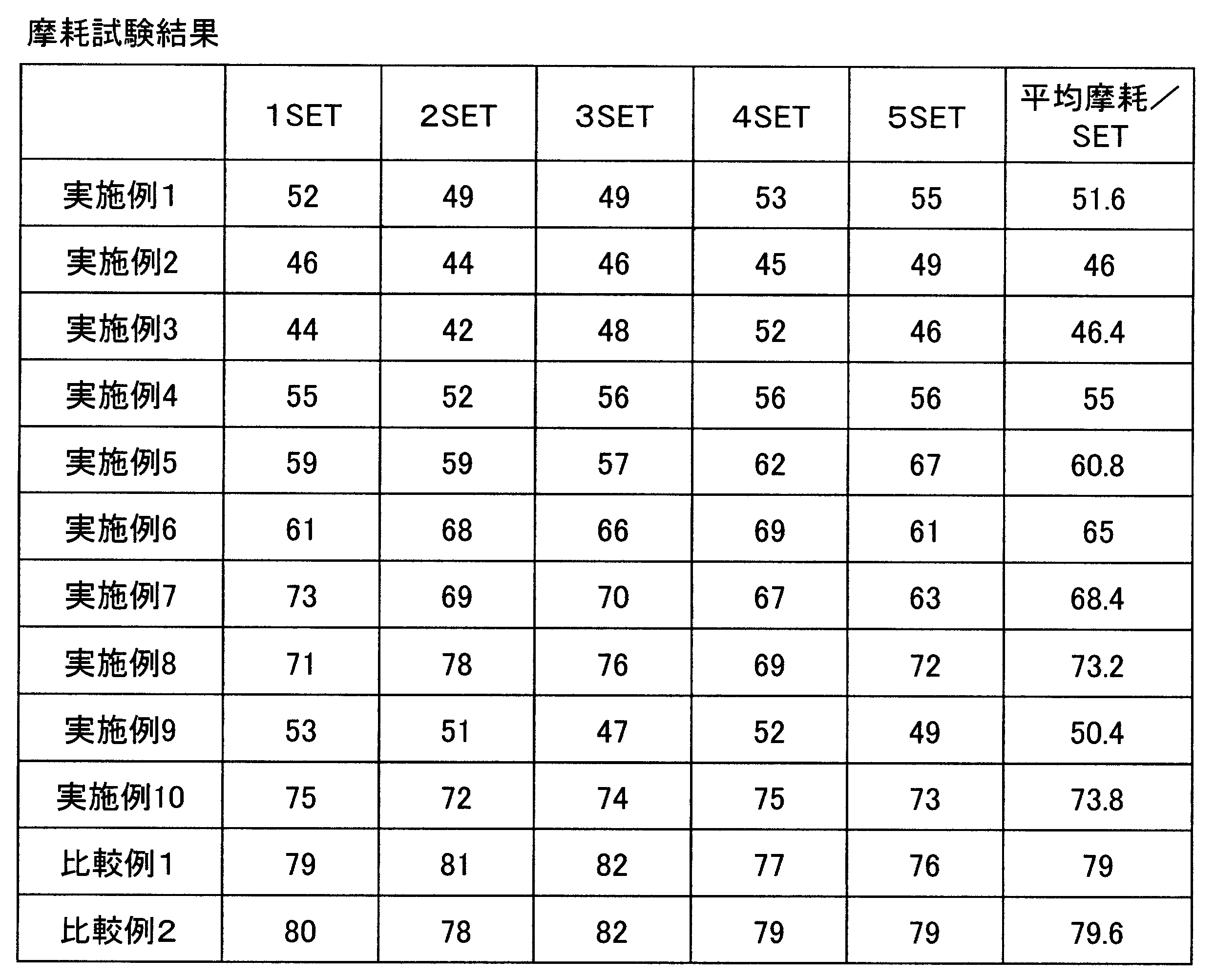
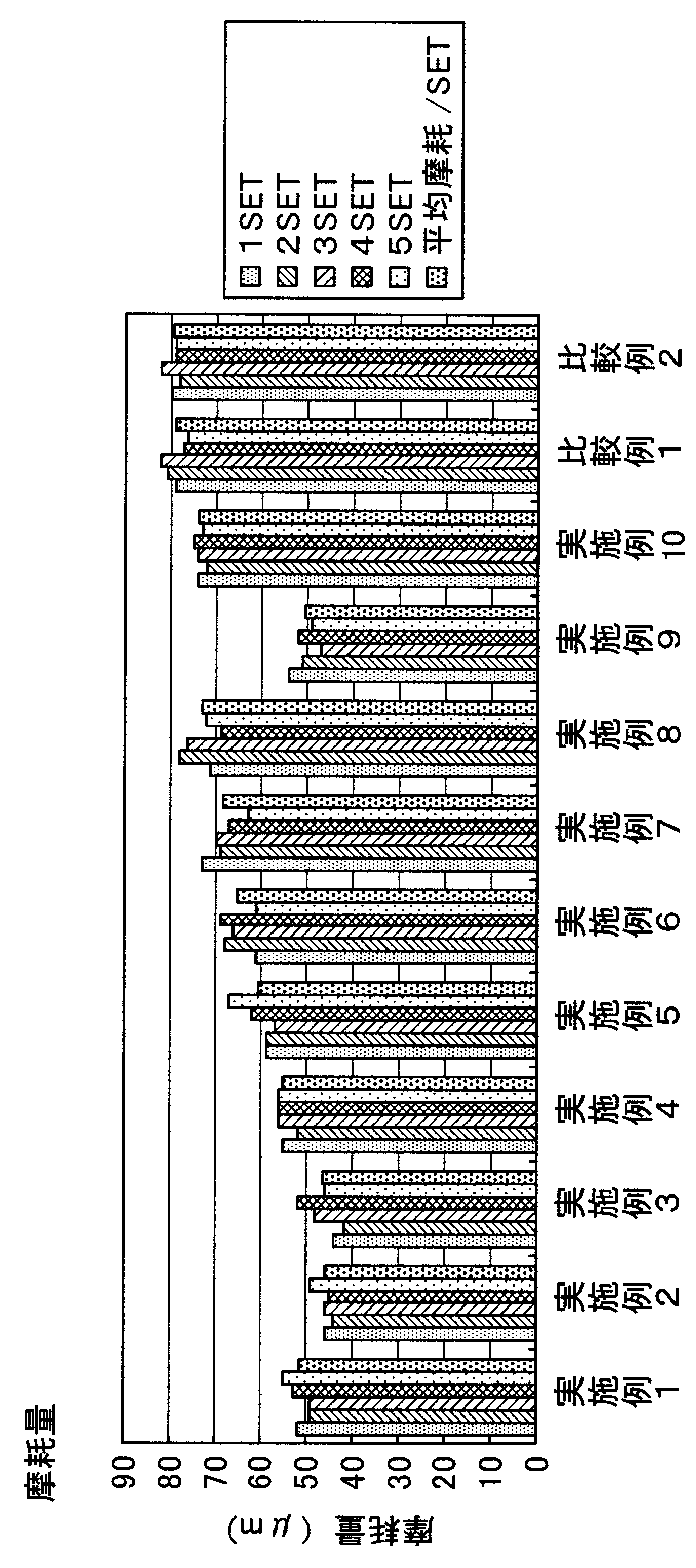
- the test conditions are as follows. Used Cider Tokyo Seimitsu / A-WD-10A Used dress plate WA # 200 Spindle speed 15000min -1 Feed speed 100mm / s Cooling water: 1.2 L / min in the circumferential direction, 0.8 L / min on both sides In addition, 30 grooving processes were performed for each set, 5 sets were performed, and a total of 150 grooving processes were performed. The abrasion test results are shown in Tables 4 and 5 below.
- Table 2 shows the average wear as a result of 5 sets
- Table 3 shows the cumulative wear after 5 sets. These wear amounts are shown in graphs in Tables 4 and 5 below.
- the cutting blades of Examples 1 to 10 to which the filler 4 having a crystal structure of zinc oxide was added had a small amount of friction, and in particular, the filler was in the range of 10% by volume or 20% by volume.
- the amount of wear of the cutting blades of Examples 2 and 3 added in Example 2 was small. This is presumed that the anisotropic relaxation function of the filler having a three-dimensional crystal structure among the fillers of the zinc oxide crystal structure was sufficiently exhibited.
- the addition ratio of the filler of the zinc oxide crystal structure became 30 volume% or more, it turned out that the bond strength of a phenol resin weakens and conversely the amount of wear increases. Further, it was found that the amount of wear was large in the cutting blades of Comparative Examples 1 and 2 that did not have a zinc oxide crystal structure filler but instead added SiC whisker or glass fiber filler.
- a disk-shaped blade having a diameter of 70 mm was cut out from a sheet molded by adopting the doctor blade method, the disk-shaped blade was compression-molded by a hot press and sintered, and the warpage of the sintered body was measured. .
- the results are shown in Table 6 below.
- the test conditions are as follows. Used Cider Tokyo Seimitsu / A-WD-10A Used dress plate WA # 200 Spindle speed 21000min -1 Feeding speed 80mm / s Cooling water: 1.2 L / min in the circumferential direction, 0.8 L / min on both sides
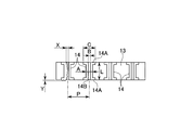
- the outer diameter d of the Cu lead frame 12 was 0.3 mm, and the pitch P between adjacent Cu lead frames 12 was 0.35 mm.
- the base material 13 made of glass epoxy resin is spaced apart by a blade for cutting the same shape, dimensions, and resin binder as in Examples 1 to 10 and Comparative Examples 1 and 2.
- the IrDA substrate on which the Ni—Cr—Au metal plating 14 was applied to the inner peripheral surface of the formed through hole so as to have flange-like portions 14A at both ends was cut.
- the cutting resistance and the wear amount and the size of the burr extending from the metal plating 14 (in the lateral direction in the through hole (as shown in FIG. 5)
- the size of burrs extending in the feed direction) is X, and the size of burrs extending downward from the bottom of the substrate is Y).
- the cutting resistance, burrs, and wear amount are all kept low from the beginning of cutting. Further, at the time of cutting 500 m, the amount of wear increases in Examples 8 and 10, and the size of burrs tends to increase particularly when cutting IrDA substrates. It can be seen that in the cutting blades of Examples 1 to 7 and 9, there is no change in the cutting resistance, and the wear amount and the size of the burr are suppressed to a sufficiently small range. It can also be seen that, among Examples 1 to 10, in Examples 2 and 3, in which the filler content of the zinc oxide crystal structure is 10% by volume and 20% by volume, the amount of wear is particularly suppressed.
- the present invention relates to a cutting blade used for cutting various electronic material parts such as a semiconductor device.
- the cutting blade of the present invention is a cutting blade having a layer shape of at least one layer, and is distributed in a bond portion, abrasive grains distributed in the bond portion, and dispersed in the bond portion.
- the filler includes a filler having a three-dimensional crystal structure in which needle-like portions extend in four directions from the center of the tetrahedron toward each vertex, and are thereby added to the bond portion.
Landscapes
- Engineering & Computer Science (AREA)
- Mechanical Engineering (AREA)
- Polishing Bodies And Polishing Tools (AREA)
- Nonmetal Cutting Devices (AREA)
- Crystals, And After-Treatments Of Crystals (AREA)
Abstract
Description
本願は、2011年2月28日に日本に出願された特願2011-041573号について優先権を主張し、その内容をここに援用する。
(a)QFN(quad flat non-leaded package)と称されるもののように、リードフレーム上に一括して多数の素子を実装してこれらをまとめてモールディングした後に切断することにより個片化されて製造される電子材料部品。
(b)IrDA(Infrared Data Association; 赤外線データ通信協会)規格の光伝送モジュール(以下、単にIrDAと略称する)のように、ガラスエポキシ樹脂製の基体に形成されたスルーホールの内周面にNi、Au、Cu等のめっきが施された基板を有し切断により個片化される電子材料部品。
このような電子材料部品の切断においては、例えばQFNではモールディング樹脂中に間隔をあけて配置されたCu等の延性の高い金属リードフレームを切断することとなるため、切断の際の薄刃砥石の送り方向や回転方向にこのリードフレーム等の金属バリが生じ易いという問題がある。
特に、ドクターブレード法を用いて成型される切断用ブレードにあっては、硬化樹脂中のウィスカー等の配列方向が一方向に定まってしまい、異方性が顕著に現れる。
加えて、前述した切断用ブレードにあっては、成型後に特定方向へ樹脂の収縮率が大きくなることに起因して、製品としての寸法精度が低下し、所望の切断性能が得られない。
このため、このようなフィラーが添加されたボンド部は、異方性が緩和されることとなり、どの方向に対しても略同一の耐摩耗性を確保でき、結果的に耐摩耗性に優れるものとなる。また、成型後のボンド部においては、特定方向への収縮率が高くなるといった事態を回避でき、製品としての寸法精度の向上が図れる。これに伴い、切断性能が向上するとともに、バリの発生を抑制できる。
金属酸化物の結晶構造体のフィラーは、損傷され易いものが多く、例え針状部が折れる等してその形状が変わる場合であっても、三次元結晶構造のフィラーと、三次元結晶構造とは異なる形状のフィラーとの体積比が10:90~90:10の範囲であれば、三次元結晶構造のフィラーの特徴である異方性を緩和する機能を充分発揮できる。
この場合、金属酸化物の結晶構造体のフィラーの体積パーセントが1~40%に設定されていれば、金属酸化物の結晶構造体のうち三次元結晶構造のものもつ機能、つまり、異方性を緩和する機能を充分発揮することができ、もって、耐摩耗性並びに切断性能の向上が図れるとともに金属バリの発生も抑えることができる。
切断用ブレードの内径部が切断装置の主軸に取り付けられて上記軸線O回りに回転されつつ該軸線Oに垂直な方向に送り出されることにより、この薄刃砥粒層1の外周縁部、すなわち上記厚さと等しい極小さな幅の外周面1Aと、両側面1Bの外周側、およびこれら外周面1Aと両側面1Bとが交差する円周状の両エッジ部1Cとによって、電子部品材料を切断する。
図3(a)には、正四面体あるいは単なる四面体の中心から各頂点に向かって針状部4aaが四方に伸びた三次元結晶構造のフィラー4aを示す。すなわち、図3(a)に示すフィラー4の結晶4aは、四方に伸びた4本の針状部4aaを有し、針状部4aaの各頂点を仮想線で相互に結ぶと四面体をなす三次元構造を有する。図3(b)には、前記三次元結晶構造のフィラー4aにおいて、4本ある針状部4aaのうちの1本が根元から折れた形状のフィラー4bを示す。すなわち、図3(b)に示すフィラー4の結晶4bは、四方に伸びた針状部4aaのうち一本が欠落した三次元構造を有する。図3(c)には、前記三次元結晶構造のフィラー4aにおいて、4本ある針状部4aaのうちの2本が根元から折れた形状のフィラー4cを示す。すなわち、図3(c)に示すフィラー4の結晶4cは、四方に伸びた針状部4aaのうち二本が欠落した構造を有する。図3(d)には、板状に形成されたフィラー4dを示す。すなわち、図3(d)に示すフィラー4の結晶4dは、針状ではなく板状に成長した構造を有する。
その他、前記三次元結晶構造のフィラー4aにおける針状部4aaの先端部分が折れてなる、単なる針状部形状のフィラーもある。すなわち、結晶4aから欠落した針状部も結晶として存在する。
また、前記酸化亜鉛の結晶構造体からなるフィラー4のうち、前記三次元結晶構造のフィラー4aと酸化亜鉛の結晶構造体からなる他の形状のフィラー(4b、4c、4d)との体積比は、10:90~90:10の範囲に設定されている。
また、前記WCからなる粉末状のフィラー5は、平均粒径が0.1~5μm程度であり、モース硬度がおおよそ8であって、モース硬度が5~6程度である前記三次元結晶構造のフィラー4aに比べて高い硬度となっている。
まず、例えばフェノール樹脂を所定量秤量し、IPA溶媒を10ml加えてフェノール樹脂を溶解させる。次に、溶解させた樹脂溶液、シランカップリング剤、並びに酸化亜鉛の結晶構造体からなるフィラー4や三次元結晶構造からなるフィラー4よりも硬度が高い例えばWCからなる粉末状のフィラー5を添加し、ドクターブレード法により、例えば、厚さ0.3mmのシートを成型する。
次いで、このシートを乾燥させた後、該シートから直径70mmの円板状ブレードをくり抜き、この円板状ブレードをホットプレスにて圧縮成型する。成型条件は、熱板200℃、180℃×30分間、圧力12.7MPaである。すなわち、200℃に熱した熱板を使用し、型に入れたブレードに180℃の温度下で30分間にわたって12.7MPaの圧力を作用させる。
こうして得られる円板状ブレードを所定サイズとなるよう、外周部と内周部を切断あるいは研削加工することで所望形状の切断用ブレードを得ることができる。
このため、このようなフィラー4aが添加された樹脂結合剤相2は、異方性が緩和されることとなり、どの方向に対しても略同一の耐摩耗性を確保でき、結果的に耐摩耗性に優れるものとなる。また、成型後の樹脂結合剤相2においては、ある方向への収縮率が高くなるといった事態が回避でき、製品としての寸法精度の向上が図れる。これに伴い、切断性能が向上するとともに、バリの発生を抑制できる。
仮に、樹脂結合剤相2に、酸化亜鉛の結晶構造のフィラー4のみで比較的硬度が高いWCからなる粉末状のフィラー5を有さない場合には、樹脂結合剤相2の磨耗が必要以上に進んでしまい、切断用ブレードとしての寿命が短くなってしまう。ここでは、フィラーとして、酸化亜鉛の結晶構造フィラー4の他に該結晶構造のフィラー4よりも硬度が高い粉末状のフィラーWCを用いているので、樹脂結合剤相2の磨耗が進むのを適宜抑えることができ、これによって、前述したように切断性能の向上並びにバリの発生を抑制する他、長寿命化を図ることもできる。
三次元結晶構造のフィラー4aの表面に微細な凹凸が生じており、この凹凸のうち凹所の底部には樹脂結合剤相2が侵入しにくい。しかしながら、三次元結晶構造のフィラー4aの表面がシランカップリング剤で予めコーティンされていると、三次元結晶構造のフィラー4aの表面の濡れ性が改善されて、樹脂結合剤相2と十分なじむこととなり、このため、三次元結晶構造のフィラー4aの表面の凹所の底部にまで、樹脂結合剤相2が侵入する。この結果、樹脂結合剤相2の三次元結晶構造のフィラー4aに対する保持力が高まり、三次元結晶構造のフィラー4aが樹脂結合剤相2からむやみに脱落するのを回避できる。
なお、三次元結晶構造のフィラー4aの表面はシランカップリング剤で予めコーティング処理する方法としては、公知の乾式処理法やスラリー法が採用される。
例えば、図1に示す切断用ブレードでは、薄刃砥粒層1が一つであるが、これに限られることなく、このような薄刃砥粒層1が複数あるものにも本発明は適用可能である。
また、前記実施形態では、樹脂結合剤相2に添加されるフィラーとしては、必ずしも、酸化亜鉛の結晶構造体からなるフィラー4に限られることなく、酸化亜鉛以外の金属酸化物の結晶構造体を添加してもよい。また、金属酸化物の結晶構造体以外のフィラーとしても、WCからなる粉末状のフィラー5に限られることなくTiやTiN、もしくはカーボン等からなる導電性を持つ粉状体や、更にウィスカーあるいはグラスファイバ等を加えてもよい。
〈第1実施例〉
本実施例では、粉末状WCであるフィラー5の含有量を一定とし(25%)、酸化亜鉛の結晶構造体であるフィラー4の添加割合を種々変えた8種、樹脂結合剤相2中にシランカップリング剤を混入することなく酸化亜鉛の結晶構造体のフィラー4の添加割合を10%としたもの、並びに樹脂結合剤相2中にシランカップリング剤を混入することなく酸化亜鉛の結晶構造体のフィラー4の添加割合を35%としかつWC粉末状のフィラー5を含まないものの合計10種の本発明に係わる切断用ブレードを用意した。この切断ブレードは、外径58mm、内径40mm、厚さ0.3mmである。また、樹脂結合剤相2はフェノール樹脂、砥粒3は粒度♯230のダイヤモンド砥粒であって集中度は75である。この切断用ブレードにより、ドレッサープレートに溝入れ加工を実施し、摩耗試験を行った。
また、上記実施例1~10と同じ形状であって、酸化亜鉛の結晶構造体4の添加する代わりに、SiCウィスカーやグラスファイバをそれぞれ10体積%添加したものを比較例1,2とし、これら比較例1,2の切断用ブレードを用いて実施例1~10と同様の摩耗試験を行った。
このときの、実施例1~10、比較例1、2の切断用ブレードの組成を下記の表1に示す。

使用サイダー東京精密製/A―WD-10A
使用ドレスプレートWA ♯200
スピンドル回転数15000min-1
送り速度100mm/s
冷却水:周方向1.2L/min、両側面0.8L/min
また、1セットごとに30本の溝入れ加工を施し、これを5セット行い、合計150本の溝入れ加工を行った。摩耗試験結果を下記の表4、表5に示す。

また、これら摩耗量を下記の表4、表5ではそれぞれグラフに表した。
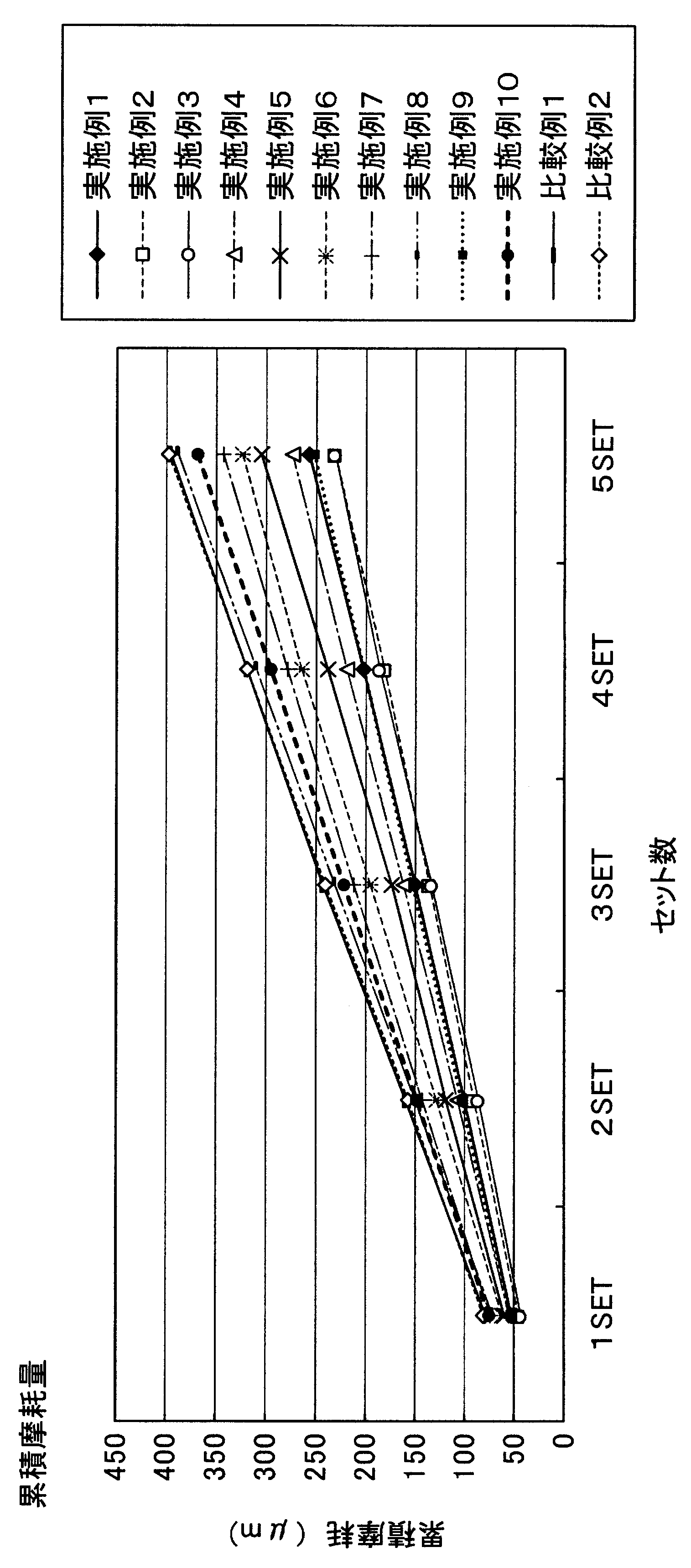
これは、酸化亜鉛の結晶構造体のフィラーのうち、三次元結晶構造のフィラーの異方性緩和機能が充分発揮されたものと推測される。なお、酸化亜鉛の結晶構造体のフィラーの添加割合が30体積%以上になると、フェノール樹脂の結合力が弱まり、逆に摩耗量が増えることがわかった。
また、酸化亜鉛の結晶構造体のフィラーを有さず、代わりにSiCウィスカーやグラスファイバのフィラーを添加した比較例1,2の切断用ブレードでは、摩耗量が大きいことがわかった。
その結果を下記の表6に示す。

〈第2実施例〉
使用サイダー東京精密製/A―WD-10A
使用ドレスプレートWA ♯200
スピンドル回転数21000min-1
送り速度80mm/s
冷却水:周方向1.2L/min、両側面0.8L/min
なお、上記Cuリードフレーム12の外径dは0.3mm、隣接するCuリードフレーム12間のピッチPは0.35mmであった。
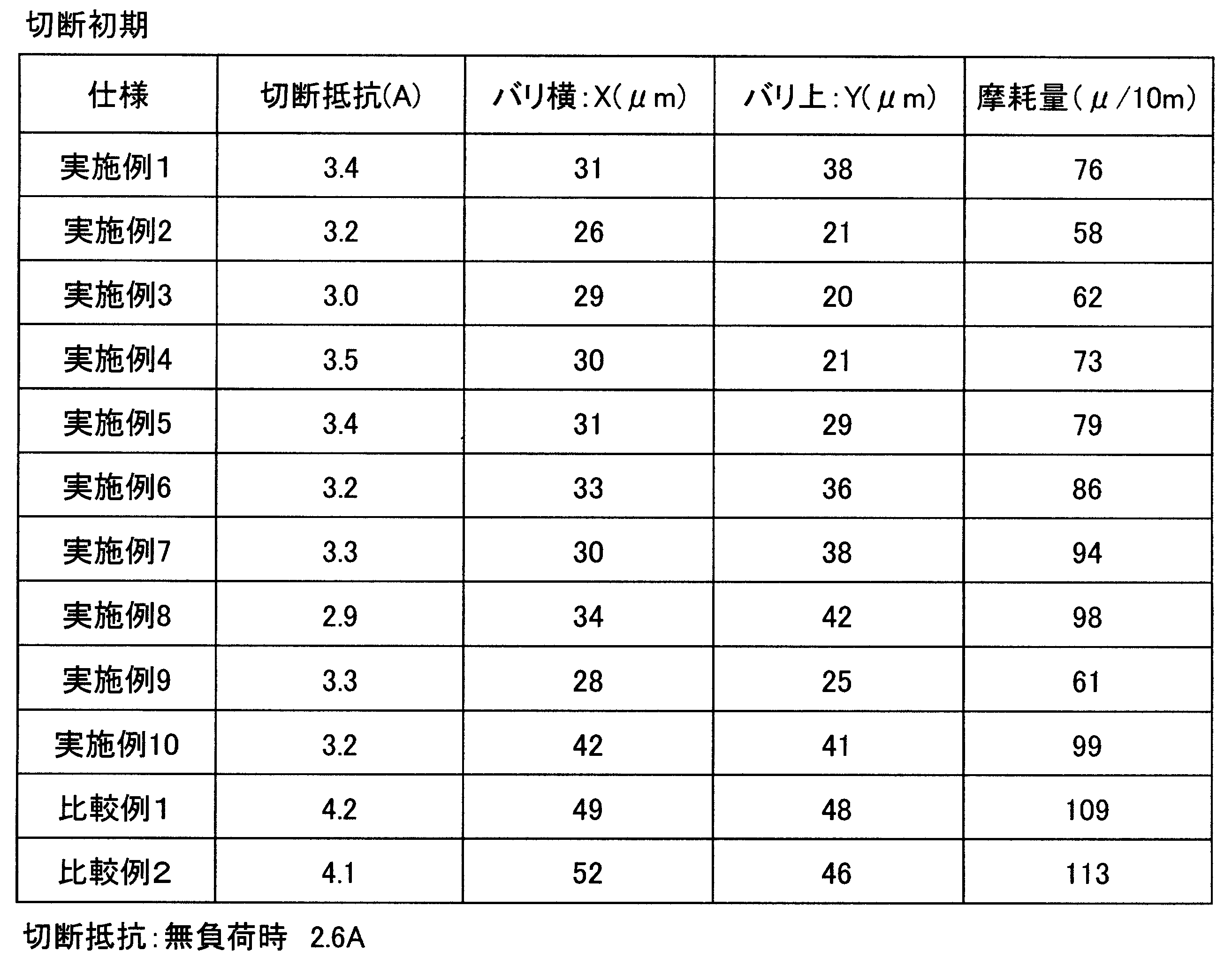
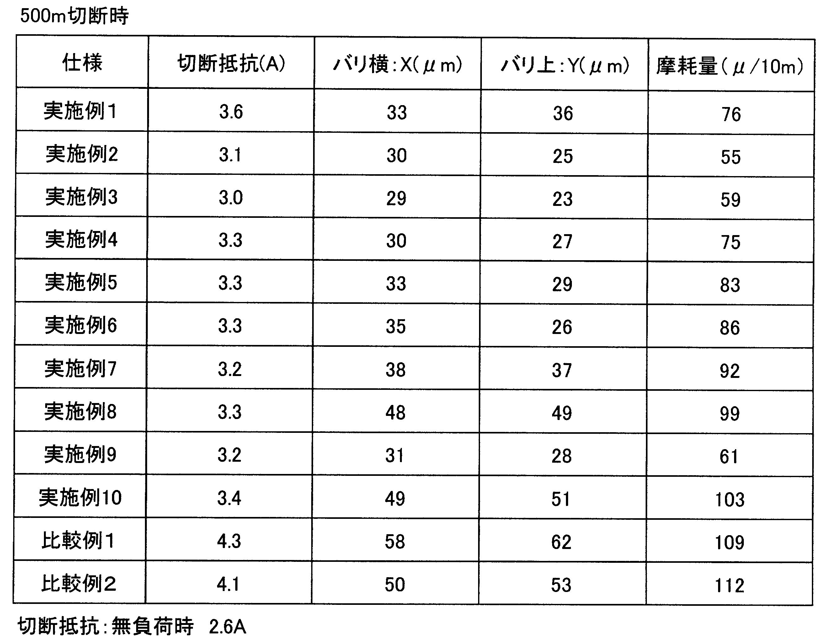
ただし、これら実施例1~10および比較例1,2の切断用ブレードを用いた試験条件は、前述したとおりである。
また、スルーホールの長さLは0.18mm、スルーホールの内径Aは0.17mm、スルーホール内周面に施された金属めっき14の内径Bは0.04mm、フランジ状部14Aの外径Cは0.7mm、隣接するスルーホール間のピッチPは2.0mmであった。
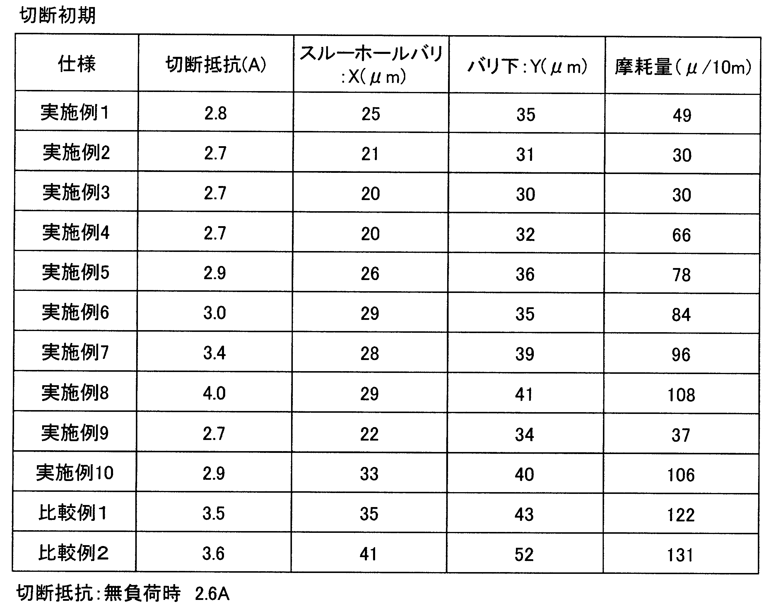
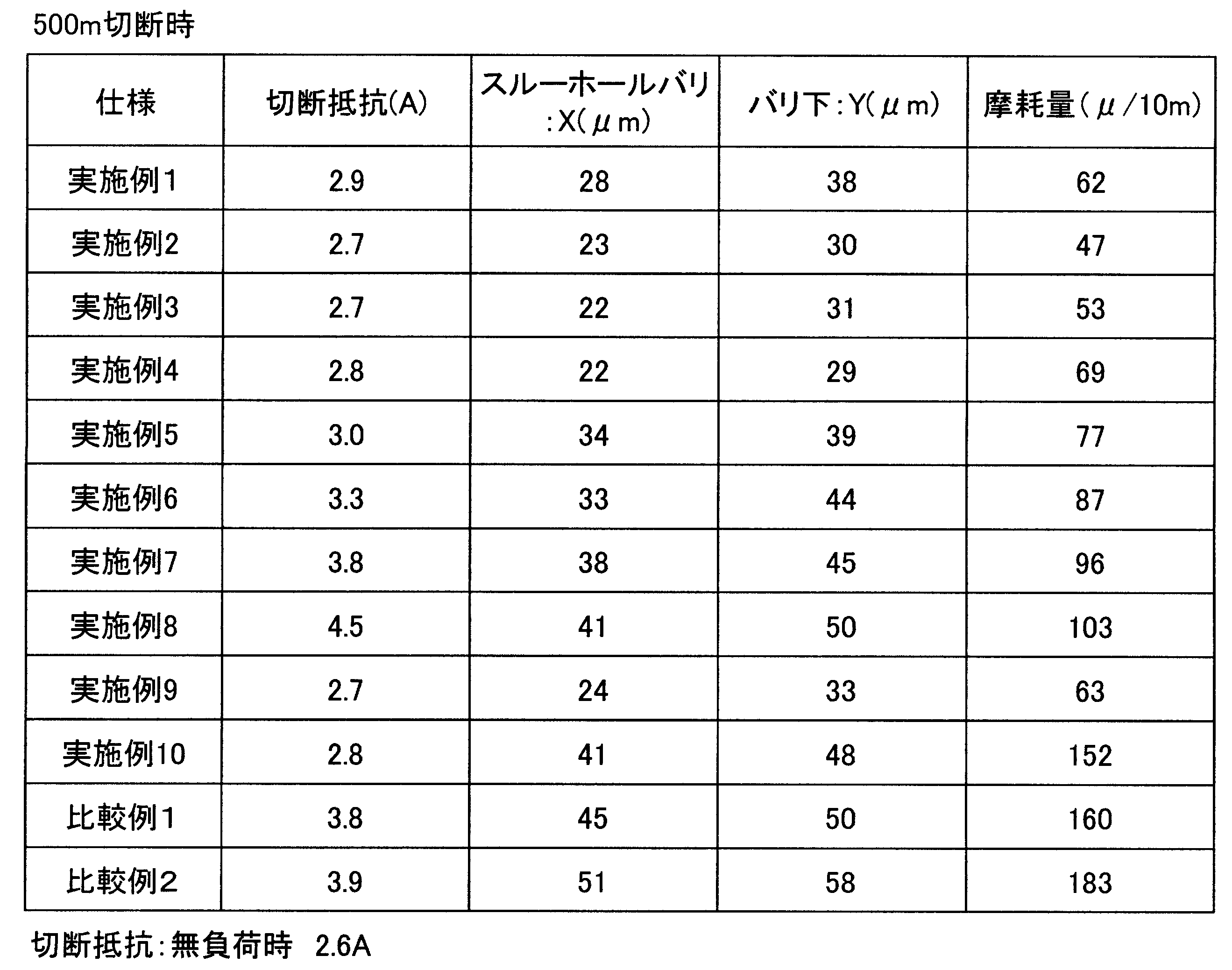
2…樹脂結合剤相(ボンド部)、
3…砥粒、
4…酸化亜鉛(金属酸化物)の結晶構造体、
4a…酸化亜鉛(金属酸化物)の三次元結晶構造のフィラー、
4aa…針状部、
5…三次元結晶構造のフィラーよりも硬度が高い粉末状のフィラー
Claims (8)
- 少なくとも1層以上の層状をなす切断用ブレードであって、
ボンド部と、
前記ボンド部中に分散配置された砥粒と、
前記ボンド部中に分散配置されたフィラーとを備え、
前記フィラーは、四面体の中心から各頂点に向かって針状部が四方に伸びた三次元結晶構造のフィラーを含む切断用ブレード。 - 請求項1記載の切断用ブレードにおいて、
前記フィラーは、前記三次元結晶構造のフィラーの他に、該三次元結晶構造のフィラーよりも硬度が高い粉末状のフィラーを有する切断用ブレード。 - 請求項1または2に記載の切断用ブレードにおいて、
前記三次元結晶構造のフィラーは、前記針状部の長さが0.1μm~100μmの範囲とされている切断用ブレード。 - 請求項1~3のいずれか一項に記載の切断用ブレードにおいて、
前記三次元結晶構造のフィラーは、金属酸化物の結晶構造体からなっている切断用ブレード。 - 請求項4に記載の切断ブレードにおいて、
前記金属酸化物の結晶構造体のフィラーは、前記三次元結晶構造のフィラーの他に、前記三次元結晶構造とは異なる形状のフィラーを備え、
それら三次元結晶構造のフィラーと、三次元結晶構造とは異なる形状のフィラーとの体積比が10:90~90:10の範囲である切断用ブレード。 - 請求項1~5のいずれか一項に記載の切断用ブレードにおいて、
前記ボンド部にシランカップリング剤が混入されている切断用ブレード。 - 請求項1~5のいずれか一項に記載の切断用ブレードにおいて、
前記三次元結晶構造のフィラーの表面がシランカップリング剤でコーティングされている切断用ブレード。 - 請求項5に記載の切断用ブレードにおいて、
砥粒抜きの前記ボンド部における、前記金属酸化物の結晶構造体のフィラーの体積パーセントが1~40%に設定されている切断用ブレード。
Priority Applications (3)
| Application Number | Priority Date | Filing Date | Title |
|---|---|---|---|
| PH1/2013/501756A PH12013501756A1 (en) | 2011-02-28 | 2011-03-29 | Cutting blade |
| CN201180068526.8A CN103517785B (zh) | 2011-02-28 | 2011-03-29 | 切割用砂轮片 |
| IL228081A IL228081A0 (en) | 2011-02-28 | 2013-08-22 | cutting blade |
Applications Claiming Priority (2)
| Application Number | Priority Date | Filing Date | Title |
|---|---|---|---|
| JP2011-041573 | 2011-02-28 | ||
| JP2011041573A JP5651045B2 (ja) | 2011-02-28 | 2011-02-28 | 切断用ブレード |
Publications (1)
| Publication Number | Publication Date |
|---|---|
| WO2012117571A1 true WO2012117571A1 (ja) | 2012-09-07 |
Family
ID=46757528
Family Applications (1)
| Application Number | Title | Priority Date | Filing Date |
|---|---|---|---|
| PCT/JP2011/057755 Ceased WO2012117571A1 (ja) | 2011-02-28 | 2011-03-29 | 切断用ブレード |
Country Status (7)
| Country | Link |
|---|---|
| JP (1) | JP5651045B2 (ja) |
| CN (1) | CN103517785B (ja) |
| IL (1) | IL228081A0 (ja) |
| MY (1) | MY162238A (ja) |
| PH (1) | PH12013501756A1 (ja) |
| TW (1) | TWI494194B (ja) |
| WO (1) | WO2012117571A1 (ja) |
Families Citing this family (1)
| Publication number | Priority date | Publication date | Assignee | Title |
|---|---|---|---|---|
| CN109648486B (zh) * | 2018-12-30 | 2020-09-22 | 苏州赛尔科技有限公司 | 引线框架分割用低磨损树脂刀及其应用 |
Citations (3)
| Publication number | Priority date | Publication date | Assignee | Title |
|---|---|---|---|---|
| JPH01115574A (ja) * | 1987-10-27 | 1989-05-08 | Canon Inc | 極薄切断ブレード |
| JP2006062009A (ja) * | 2004-08-25 | 2006-03-09 | Mitsubishi Materials Corp | レジンボンド薄刃砥石 |
| JP2007038337A (ja) * | 2005-08-02 | 2007-02-15 | Noritake Super Abrasive:Kk | レジンボンドホイール |
Family Cites Families (10)
| Publication number | Priority date | Publication date | Assignee | Title |
|---|---|---|---|---|
| CN1129506C (zh) * | 1997-02-14 | 2003-12-03 | 住友电气工业株式会社 | 线锯及其制造法 |
| KR100407227B1 (ko) * | 1998-09-25 | 2003-11-28 | 미쓰비시 마테리알 가부시키가이샤 | 복합본드숫돌 및 수지결합상을 보유하는 숫돌 |
| US6458018B1 (en) * | 1999-04-23 | 2002-10-01 | 3M Innovative Properties Company | Abrasive article suitable for abrading glass and glass ceramic workpieces |
| JP2001038638A (ja) * | 1999-07-26 | 2001-02-13 | Mitsubishi Materials Corp | レジンボンド砥石 |
| JP2001138244A (ja) * | 1999-08-17 | 2001-05-22 | Mitsubishi Materials Corp | レジンボンド砥石 |
| CN101092024A (zh) * | 2000-04-28 | 2007-12-26 | 3M创新有限公司 | 研磨制品以及研磨玻璃的方法 |
| JP2002105750A (ja) * | 2000-09-25 | 2002-04-10 | Shimadzu Corp | 草刈り機用モノフィラメント及びその製造方法 |
| JP2005095992A (ja) * | 2003-09-22 | 2005-04-14 | Nitolex Honsha:Kk | レーザーツルーイング・ドレッシング方法、および、レーザーツルーイング・ドレッシング用の砥石 |
| JP4779580B2 (ja) * | 2005-11-02 | 2011-09-28 | 三菱マテリアル株式会社 | 電鋳薄刃砥石 |
| US8808412B2 (en) * | 2006-09-15 | 2014-08-19 | Saint-Gobain Abrasives, Inc. | Microfiber reinforcement for abrasive tools |
-
2011
- 2011-02-28 JP JP2011041573A patent/JP5651045B2/ja active Active
- 2011-03-29 CN CN201180068526.8A patent/CN103517785B/zh not_active Expired - Fee Related
- 2011-03-29 MY MYPI2013003108A patent/MY162238A/en unknown
- 2011-03-29 WO PCT/JP2011/057755 patent/WO2012117571A1/ja not_active Ceased
- 2011-03-29 PH PH1/2013/501756A patent/PH12013501756A1/en unknown
- 2011-03-30 TW TW100110937A patent/TWI494194B/zh active
-
2013
- 2013-08-22 IL IL228081A patent/IL228081A0/en unknown
Patent Citations (3)
| Publication number | Priority date | Publication date | Assignee | Title |
|---|---|---|---|---|
| JPH01115574A (ja) * | 1987-10-27 | 1989-05-08 | Canon Inc | 極薄切断ブレード |
| JP2006062009A (ja) * | 2004-08-25 | 2006-03-09 | Mitsubishi Materials Corp | レジンボンド薄刃砥石 |
| JP2007038337A (ja) * | 2005-08-02 | 2007-02-15 | Noritake Super Abrasive:Kk | レジンボンドホイール |
Also Published As
| Publication number | Publication date |
|---|---|
| JP5651045B2 (ja) | 2015-01-07 |
| JP2012176472A (ja) | 2012-09-13 |
| IL228081A0 (en) | 2013-09-30 |
| TW201235156A (en) | 2012-09-01 |
| MY162238A (en) | 2017-05-31 |
| CN103517785B (zh) | 2016-06-29 |
| PH12013501756A1 (en) | 2015-12-04 |
| TWI494194B (zh) | 2015-08-01 |
| CN103517785A (zh) | 2014-01-15 |
Similar Documents
| Publication | Publication Date | Title |
|---|---|---|
| US9221153B2 (en) | Preparation method of diamond-metal sawblades in reactive sintering production for singulating QFN packaging device | |
| US11458594B2 (en) | Method for manufacturing cutting blade, and cutting blade | |
| JP5061018B2 (ja) | アルミニウム−黒鉛−炭化珪素質複合体及びその製造方法 | |
| JP5841437B2 (ja) | 切断用ブレード及びその製造方法 | |
| JP5841438B2 (ja) | 切断用ブレード | |
| JP5651045B2 (ja) | 切断用ブレード | |
| JP5528064B2 (ja) | 切断用ブレード | |
| JP2006082187A (ja) | 薄刃砥石 | |
| JP2010179438A (ja) | 切断ブレード及びその製造方法並びに中間体 | |
| JP6207015B2 (ja) | 切断用ブレード及びその製造方法 | |
| JP7614745B2 (ja) | 切断用ブレード | |
| JP6641590B2 (ja) | 切断用ブレードの製造方法 | |
| JP2009006409A (ja) | 薄刃砥石 | |
| JP2006062009A (ja) | レジンボンド薄刃砥石 | |
| JP5676324B2 (ja) | 樹脂ボンド砥石 | |
| JP7829276B2 (ja) | 切断用ブレード | |
| JP6641591B2 (ja) | 切断用ブレードの製造方法 | |
| JP5908146B2 (ja) | 切断用ブレードの製造方法 | |
| JP2012192487A (ja) | 切断ブレード | |
| JP5729809B2 (ja) | 凝集砥粒 | |
| KR102160096B1 (ko) | 고경도 고취성 기판의 고속 가공을 위한 래핑 플레이트 및 이를 이용한 기판 연마 장치 | |
| JP2006150500A (ja) | レジンボンド砥石およびそれを用いた半導体チップの製造方法 | |
| JP5725733B2 (ja) | 薄刃ブレード | |
| JP5451245B2 (ja) | 切断ブレード | |
| TW202142703A (zh) | 複合聚晶鑽石片及其組成與製作方法 |
Legal Events
| Date | Code | Title | Description |
|---|---|---|---|
| 121 | Ep: the epo has been informed by wipo that ep was designated in this application |
Ref document number: 11859708 Country of ref document: EP Kind code of ref document: A1 |
|
| WWE | Wipo information: entry into national phase |
Ref document number: 12013501756 Country of ref document: PH |
|
| NENP | Non-entry into the national phase |
Ref country code: DE |
|
| WWE | Wipo information: entry into national phase |
Ref document number: 1301004737 Country of ref document: TH |
|
| 122 | Ep: pct application non-entry in european phase |
Ref document number: 11859708 Country of ref document: EP Kind code of ref document: A1 |