WO2012117543A1 - 電力貯蔵電池 - Google Patents
電力貯蔵電池 Download PDFInfo
- Publication number
- WO2012117543A1 WO2012117543A1 PCT/JP2011/054798 JP2011054798W WO2012117543A1 WO 2012117543 A1 WO2012117543 A1 WO 2012117543A1 JP 2011054798 W JP2011054798 W JP 2011054798W WO 2012117543 A1 WO2012117543 A1 WO 2012117543A1
- Authority
- WO
- WIPO (PCT)
- Prior art keywords
- charge
- positive electrode
- electrode electrolyte
- negative electrode
- aqueous solution
- Prior art date
- Legal status (The legal status is an assumption and is not a legal conclusion. Google has not performed a legal analysis and makes no representation as to the accuracy of the status listed.)
- Ceased
Links
Images

Classifications
-
- H—ELECTRICITY
- H01—ELECTRIC ELEMENTS
- H01M—PROCESSES OR MEANS, e.g. BATTERIES, FOR THE DIRECT CONVERSION OF CHEMICAL ENERGY INTO ELECTRICAL ENERGY
- H01M8/00—Fuel cells; Manufacture thereof
- H01M8/18—Regenerative fuel cells, e.g. redox flow batteries or secondary fuel cells
- H01M8/184—Regeneration by electrochemical means
- H01M8/188—Regeneration by electrochemical means by recharging of redox couples containing fluids; Redox flow type batteries
-
- Y—GENERAL TAGGING OF NEW TECHNOLOGICAL DEVELOPMENTS; GENERAL TAGGING OF CROSS-SECTIONAL TECHNOLOGIES SPANNING OVER SEVERAL SECTIONS OF THE IPC; TECHNICAL SUBJECTS COVERED BY FORMER USPC CROSS-REFERENCE ART COLLECTIONS [XRACs] AND DIGESTS
- Y02—TECHNOLOGIES OR APPLICATIONS FOR MITIGATION OR ADAPTATION AGAINST CLIMATE CHANGE
- Y02E—REDUCTION OF GREENHOUSE GAS [GHG] EMISSIONS, RELATED TO ENERGY GENERATION, TRANSMISSION OR DISTRIBUTION
- Y02E60/00—Enabling technologies; Technologies with a potential or indirect contribution to GHG emissions mitigation
- Y02E60/30—Hydrogen technology
- Y02E60/50—Fuel cells
Definitions
- the present invention relates to a power storage battery such as a redox flow battery.
- Patent Document 1 and Non-Patent Document 1 describe a configuration (electromotive force) in which hydrochloric acid (solvent is water) is used as the electrolyte, the positive electrode electrolyte is an aqueous hydrochloric acid solution of iron chloride, and the negative electrode electrolyte is an aqueous hydrochloric acid solution of chromium chloride. Is about 1.0V).
- Patent Documents 2 and 3 and Non-Patent Document 2 sulfuric acid (solvent is water) is used as the electrolyte, and the positive and negative electrolytes are vanadium sulfate aqueous solutions (electromotive force is about 1.4 V). )
- the electrolyte in each of these structures is strongly acidic, and there are difficulties in handling and selection of the battery container material. Therefore, a redox flow battery using a weakly acidic, neutral, or weakly alkaline (pH 3 to 8) electrolyte is required.
- Non-Patent Documents 3 to 5 propose a configuration in which the negative electrode electrolyte is an aqueous solution of a Cr-EDTA (ethylenediaminetetraacetic acid) complex.
- the above Cr-EDTA complex can satisfactorily perform a redox reaction under conditions of pH 3-8.
- the positive electrode electrolyte in each of these structures is strongly acidic, and therefore there are still difficulties in handling and selection of battery container materials.
- Non-Patent Document 6 sodium acetate (solvent is water) is used as the electrolyte, the negative electrode electrolyte is a sodium acetate aqueous solution of Cr—EDTA complex, and the positive electrode electrolyte is a sodium acetate aqueous solution of Cr—EDTA complex. And a configuration in which the positive electrode electrolyte is a sodium acetate aqueous solution of Fe-EDTA complex (electromotive force is about 1.2 V) are proposed.
- Non-Patent Document 6 allows the redox reaction of the negative electrode side active material Cr-EDTA complex to be carried out satisfactorily on the negative electrode side under the conditions of pH 3-8.
- Cr compound ions cannot be dissolved in water and self-discharged, so that the charge / discharge cycle characteristics (reversibility) are inferior, and the Coulomb efficiency (50% or less) and It is inferior in energy efficiency and is not suitable as a power storage battery to be used repeatedly.
- the positive electrode electrolyte is an aqueous sodium acetate solution of Fe-EDTA complex, the ions of the Fe compound cannot be dissolved in water and precipitate on the positive electrode side under the conditions of pH 3-8.
- transition metals generally used in redox flow type batteries are used.
- the oxide or hydroxide becomes insoluble in water and precipitates under conditions of pH 3-8.
- the region in which transition metal ions can be dissolved in water is extremely narrow (the ions can be dissolved in water under strongly acidic conditions, but the ions are water under conditions of pH 3-8. Can not be dissolved in).
- the present inventor has intensively studied to find a suitable active material on the positive electrode side. That is, the inventors have eagerly searched for a compound containing a metal that can change its valence in an ionic state without causing the oxide or hydroxide to be insoluble in water under the conditions of pH 3-8.
- Mn is determined from the potential-pH diagram that oxides (MnO 2 and Mn 2 O 3 ) generated by charging and discharging are insoluble in water and precipitate, By doing so, it was found that the valence can be changed in an ionic state without the oxide or hydroxide being insoluble in water under the conditions of pH 3-8.
- the present invention was completed.
- the present invention has been made in view of the above problems, and its main purpose is that the pH of the positive electrode electrolyte and the negative electrode electrolyte is in the range of 3 to 8, which is excellent in handleability and charge / discharge.
- An object of the present invention is to provide a power storage battery excellent in various performances such as cycle characteristics (reversibility), energy efficiency, and Coulomb efficiency.
- the power storage battery according to the present invention has an aminopolycarboxylic acid chelate wherein the pH of the positive electrode electrolyte and the negative electrode electrolyte is in the range of 3 to 8, and the positive electrode electrolyte is Mn. It is characterized by being an aqueous solution containing.
- the aminopolycarboxylic acid chelate of Mn used as the active material on the positive electrode side does not generate oxides or hydroxides within a pH range of 3 to 8, and therefore has good charge / discharge cycle characteristics (reversibility).
- it is excellent in energy efficiency and coulomb efficiency, and can withstand the use of several thousand cycles, so it has excellent performance as a power storage battery that is used repeatedly.
- the positive electrode electrolyte and the negative electrode electrolyte are not strongly acidic, they are excellent in handleability and increase the degree of freedom in selecting the battery container material.
- the positive electrode electrolyte and the negative electrode electrolyte are strongly acidic, there are restrictions on the selection of materials that can be used as battery containers (for example, hydrolyzed plastic cannot be used), Since the positive electrode electrolyte and the negative electrode electrolyte are not strongly acidic, general-purpose plastics and relatively inexpensive metals such as Sn, Al, Ti, Cu, Fe, and Ni can be used. Therefore, according to said structure, while being excellent in handleability, the power storage battery excellent in various performances, such as charging / discharging cycling characteristics (reversibility), energy efficiency, and Coulomb efficiency, can be provided comparatively cheaply. .
- the positive electrode electrolyte is more preferably an aqueous solution containing a Mn-EDTA complex, and the concentration of the Mn-EDTA complex in the aqueous solution is 0.2 mol / L or more, 1.0 More preferably, it is at most mol / L.
- the negative electrode electrolyte is more preferably an aqueous solution containing a Cr—EDTA complex.
- the positive electrode electrolyte and the negative electrode electrolyte are more preferably an aqueous solution containing a Mn-EDTA complex and a Cr-EDTA complex.
- the power storage battery according to the present invention is more preferably a redox flow battery.
- the concentration of the Mn-EDTA complex in the aqueous solution is set to a relatively high concentration (1.0 mol / L or less). Therefore, the energy density of the power storage battery can be increased.
- the positive electrode electrolyte and the negative electrode electrolyte are aqueous solutions containing a Mn-EDTA complex and a Cr-EDTA complex (so-called premix method)
- the capacity of the power storage battery (Various performances) can be kept constant for a longer period of time, so that the maintenance of the power storage battery becomes easier.
- the power storage battery of the present invention it is possible to provide a power storage battery that is excellent in handleability and excellent in various performances such as charge / discharge cycle characteristics (reversibility), energy efficiency, and coulomb efficiency at a relatively low cost. There is an effect that can be.
- the power storage battery according to the present invention is easy to mass-produce (industrialize) at a relatively low cost as compared with the conventional power storage battery.
- the power storage battery according to the present invention has a configuration in which the pH of the positive electrode electrolyte and the negative electrode electrolyte is in the range of 3 to 8, and the positive electrode electrolyte is an aqueous solution containing an aminopolycarboxylic acid chelate of Mn.
- Mn aminopolycarboxylic acid chelate refers to a Mn complex (organometallic complex) using aminopolycarboxylic acid as a chelating agent.
- pH 3 to 8 means that the pH is 3 or more and 8 or less.
- EDTA refers to ethylenediaminetetraacetic acid.
- a redox flow battery is taken as an example of the power storage battery.
- the present invention is not limited to this, and can be implemented in a mode in which various modifications are added within the range described.
- the redox flow battery 1 mainly includes a charge / discharge cell (battery container) 2, a positive electrode electrolyte tank 3, and a negative electrode electrolyte tank 4.
- the inside of the charge / discharge cell 2 is partitioned into a positive electrode side cell 2a and a negative electrode side cell 2b by a diaphragm 11 made of, for example, an ion exchange membrane.
- the charge / discharge cell 2 may be provided with a temperature control device that keeps the temperature constant.
- the positive electrode side cell 2a accommodates a current collector plate 12 such as a glassy carbon plate and a positive electrode 13 made of, for example, carbon felt.
- the negative electrode side cell 2b accommodates a current collector plate 14 such as a glassy carbon plate and a negative electrode 15 made of, for example, carbon felt.
- the positive electrode 13 is impregnated with a positive electrode electrolyte
- the negative electrode 15 is impregnated with a negative electrode electrolyte. Since the positive electrode electrolyte and the negative electrode electrolyte are not strongly acidic and poor in corrosivity, they are excellent in handleability.
- the current collecting plates 12 and 14 are electrically connected to the charging / discharging device 10.
- the positive electrode 13 performs a reduction reaction and receives electrons
- the negative electrode 15 performs an oxidation reaction and emits electrons.
- the current collecting plate 12 receives electrons from the charging / discharging device 10 and supplies them to the positive electrode 13, and the current collecting plate 14 collects electrons emitted from the negative electrode 15 and collects them in the charging / discharging device 10. It comes to supply.
- the positive electrode 13 performs an oxidation reaction and emits electrons
- the negative electrode 15 performs a reduction reaction and receives electrons.
- the current collector 12 collects the electrons emitted from the positive electrode 13 and supplies them to the charging / discharging device 10.
- the current collector 14 receives the electrons from the charging / discharging device 10 and supplies them to the negative electrode 15. It comes to supply.
- the positive electrode electrolyte tank 3 is a tank for storing the positive electrode electrolyte, and is connected to the positive electrode side cell 2a. That is, the positive electrode electrolyte tank 3 supplies the positive electrode electrolyte to the positive electrode 13 in the positive electrode side cell 2a through the supply pipe 3a, and the positive electrode electrolyte that has passed through the positive electrode 13 passes through the recovery pipe 3b. It comes to collect.
- the positive electrode electrolyte is circulated by a pump 5 provided in the supply pipe 3a.
- the supply amount of the positive electrode electrolyte per unit time to the positive electrode side cell 2a at the time of charge / discharge and the capacity of the positive electrode electrolyte tank 3 depend on the size of the charge / discharge cell 2, the capacity required for the redox flow battery 1 and the like. There is no particular limitation.
- the negative electrode electrolyte tank 4 is a tank for storing the negative electrode electrolyte, and is connected to the negative electrode side cell 2b. That is, the negative electrode electrolyte tank 4 supplies the negative electrode electrolyte to the negative electrode 15 in the negative electrode side cell 2b through the supply pipe 4a, and the negative electrode electrolyte that has passed through the negative electrode 15 passes through the recovery pipe 4b. It comes to collect.
- the negative electrode electrolyte is circulated by a pump 6 provided in the supply pipe 4a.
- the supply amount of the negative electrode electrolyte per unit time to the negative electrode side cell 2b during charge / discharge and the capacity of the negative electrode electrolyte tank 4 depend on the size of the charge / discharge cell 2 and the capacity required of the redox flow battery 1 and the like. There is no particular limitation.
- the electrolyte in the charge / discharge cell 2 can be exchanged. Therefore, in the redox flow battery 1 according to the present embodiment, a long-time (so-called large-capacity battery). ) Charging and discharging are possible.
- the charge / discharge cell 2, the positive electrode electrolyte tank 3 and the negative electrode electrolyte tank 4 are supplied with an inert gas such as nitrogen gas from a gas supply device (not shown) through an inert gas supply pipe 7. Thereby, the positive electrode electrolyte and the negative electrode electrolyte are shielded from oxygen in the atmosphere.
- the inert gas supplied from the inert gas supply pipe 7 is exhausted to the outside through the exhaust pipe 8.
- the front end of the exhaust pipe 8 is sealed with a water-sealed pipe 9 to prevent backflow of the atmosphere and keep the air pressure in the charge / discharge cell 2, the positive electrode electrolyte tank 3 and the negative electrode electrolyte tank 4 constant. ing.
- the inert gas supply pipe 7 may supply an inert gas to the gas phase portion of the charge / discharge cell 2 and the positive electrode electrolyte tank 3 and the negative electrode electrolyte tank 4. And you may come to supply by bubbling in a negative electrode electrolyte solution.
- the material of each constituent member constituting the redox flow battery 1 Great freedom of choice. That is, if the positive electrode electrolyte and the negative electrode electrolyte are strongly acidic, there are restrictions on the selection of materials that can be used as battery containers (for example, plastics that are hydrolyzed cannot be used), Since the positive electrode electrolyte and the negative electrode electrolyte are not strongly acidic, specific examples of the material of the charge / discharge cell 2 include, for example, general-purpose plastics and relatively, such as Sn, Al, Ti, Cu, Fe, and Ni. An inexpensive metal can be used.
- the materials exemplified above can also be used as materials for the positive electrode electrolyte tank 3, the pump 5, the supply pipe 3a, the recovery pipe 3b, the negative electrode electrolyte tank 4, the pump 6, the supply pipe 4a, and the recovery pipe 4b. Therefore, the redox flow battery 1 can be manufactured at a relatively low cost. Further, since it is poorly corrosive, the service life of the redox flow battery 1 is longer than that of a conventional redox flow battery (using a strongly acidic electrolyte). Therefore, the redox flow battery 1 is easy to mass-produce (industrialize) at a relatively low cost as compared with the conventional redox flow battery (using a strongly acidic electrolyte).
- each constituent member constituting the redox flow type battery 1 has an appropriate mechanical strength sufficient to maintain the apparatus, and may be made of a material that is not corroded by the positive electrode electrolyte and the negative electrode electrolyte.
- the material is not limited to the above exemplified materials.
- the negative electrode electrolyte has a pH in the range of 3 to 8, more preferably in the range of 4 to 7, and can perform a good redox reaction under the conditions of pH 3 to 8 (charged in the ionic state).
- the aqueous solution may contain an active material on the negative electrode side (which changes in number).
- Specific examples of the negative electrode electrolyte include an aqueous solution containing a Cr-EDTA complex, an aqueous solution containing a Ti-EDTA complex, an aqueous solution containing a V-EDTA complex, and an aqueous solution containing an Fe-EDTA complex. Of these, an aqueous solution containing a Cr-EDTA complex is most preferred.
- the concentration of the Cr—EDTA complex in the aqueous solution is preferably 0.2 mol / L or more and 1.0 mol / L or less, more preferably Is 0.4 mol / L or more and 0.8 mol / L or less, more preferably about 0.6 mol / L.
- the negative electrode electrolyte is an aqueous solution containing a Cr-EDTA complex
- the complex becomes a Cr (II) -EDTA complex in a charged state, and becomes a Cr (III) -EDTA complex that emits electrons in a discharged state.
- the negative electrode electrolyte solution may further contain a known electrolyte such as sodium acetate or a sodium salt of EDTA in addition to the complex.
- a known electrolyte such as sodium acetate or a sodium salt of EDTA
- the preparation method of a negative electrode electrolyte solution can employ
- the water used for the negative electrode electrolyte is sufficient if it has a purity equivalent to or higher than that of distilled water.
- the positive electrode electrolyte has a pH in the range of 3 to 8, more preferably in the range of 4 to 7, and can perform a good redox reaction under the conditions of pH 3 to 8 (charged in an ionic state).
- the active material on the positive electrode side (which changes in number), that is, the positive electrode electrolyte solution may be an aqueous solution containing Mn aminopolycarboxylic acid chelate.
- the positive electrode electrolyte solution may further contain a known electrolyte such as sodium acetate or a sodium salt of EDTA in addition to the complex.
- the preparation method of positive electrode electrolyte solution can employ
- the water used for the positive electrode electrolyte is sufficient if it has a purity equivalent to or higher than that of distilled water.
- aminopolycarboxylic acid constituting the Mn aminopolycarboxylic acid chelate include, for example, nitrilotriacetic acid ⁇ NTA (Nitrilotriacetic acid); N (CH 2 COOH) 3 ⁇ and salts thereof, ethylenediaminetetraacetic acid ⁇ EDTA (Ethylene Diamine tetraacetic acid) ; (CH 2 COOH) 2 NCH 2 CH 2 N (CH 2 COOH) 2 ⁇ and salts thereof, diethylenetriaminepentaacetic acid ⁇ DTPA (diethylene Triamine pentaacetic acid) ; (CH 2 COOH) 2 NCH 2 CH 2 N (CH 2 COOH) CH 2 CH 2 N (CH 2 COOH) 2 ⁇ and salts thereof, triethylenetetraamine hexaacetic acid (TTHA); (CH 2 COOH) 2 NCH 2 CH 2 N (CH 2 COOH) CH 2 CH 2 N (CH 2 COOH ) CH 2 CH 2 N (CH 2 COOH )
- aminopolycarboxylic acid salt examples include alkali metal salts.
- aminopolycarboxylic acids ethylenediaminetetraacetic acid and salts thereof are more preferred, and ethylenediaminetetraacetic acid / tetrasodium salt (EDTA (4Na)) is more preferred.
- EDTA (4Na) ethylenediaminetetraacetic acid / tetrasodium salt
- the Mn aminopolycarboxylic acid chelate is more preferably an Mn ethylenediaminetetraacetic acid chelate, that is, a Mn-EDTA complex.
- the redox flow battery 1 using an aqueous solution containing a Mn-EDTA complex as a positive electrode electrolyte has an excellent charge / discharge reaction rate.
- the method for preparing an Mn aminopolycarboxylic acid chelate using an inorganic compound of Mn and an aminopolycarboxylic acid as a starting material is not particularly limited, and a known chelating method can be employed. That is, the method for preparing Mn aminopolycarboxylic acid chelate is not particularly limited.
- the inorganic compound of Mn may be a water-soluble compound (solubility of 0.2 mol / L or more) suitable for chelation.
- the concentration of the Mn-EDTA complex in the aqueous solution is preferably 0.2 mol / L or more and 1.0 mol / L or less, more preferably Is 0.4 mol / L or more and 0.8 mol / L or less, more preferably about 0.6 mol / L.
- the positive electrode electrolyte is an aqueous solution containing a Mn-EDTA complex
- the complex becomes a Mn (III) -EDTA complex that has released electrons in a charged state, and becomes a Mn (II) -EDTA complex in a discharged state.
- the positive electrode electrolyte is an aqueous solution containing a Mn-EDTA complex, since Mn has a relatively high electromotive force, a high-power redox flow battery of 1.85 V or more can be provided.
- the redox flow battery has higher energy efficiency and better charge / discharge cycle characteristics (reversibility) when the coulomb efficiency is higher.
- the Coulomb efficiency is preferably 65% or more, and more preferably 80% or more.
- the energy efficiency is preferably 40% or more, and more preferably 60% or more.
- the charge / discharge cycle characteristics (reversibility) are preferably 90% or more practically.
- the voltage efficiency is preferably 60% or more practically, and more preferably 75% or more.
- the utilization factor of the electrolytic solution is preferably 28% or more, and more preferably 55% or more.
- the redox flow battery 1 uses an aqueous solution containing a Mn aminopolycarboxylic acid chelate as the positive electrode electrolyte and having a pH in the range of 3 to 8, the Coulomb efficiency is 65% or more, More preferably, it can be 80% or more. Further, the energy efficiency can be 40% or more, more preferably 60% or more. Furthermore, the charge / discharge cycle characteristics (reversibility) can be 90% or more. Further, the voltage efficiency can be 60% or more, more preferably 75% or more. Furthermore, the utilization factor of the electrolytic solution can be 28% or more, more preferably 75% or more.
- the redox flow type battery 1 since the redox flow type battery 1 according to the present embodiment can withstand the use of several thousand cycles, it can be suitably used as a power storage battery. Specific methods for calculating various performances (charge / discharge cycle characteristics (reversibility), Coulomb efficiency, voltage efficiency, energy efficiency, and utilization rate of electrolyte) will be described in the following examples.
- the diaphragm 11 which partitions the inside of the charge / discharge cell 2 into the positive electrode side cell 2a and the negative electrode side cell 2b can be separated to some extent so as not to mix the positive electrode electrolyte and the negative electrode electrolyte, Since the performance is not 100%, it is impossible to completely block the passage of the active material (the active material is mixed together). Therefore, when the redox flow battery 1 is used for a long period of time, so-called cross contamination occurs, the positive electrode side active material gradually moves to the negative electrode side, the negative electrode side active material gradually moves to the positive electrode side, A state close to equilibrium will be reached. That is, the composition of the positive electrode electrolyte and the composition of the negative electrode electrolyte are close to each other.
- the amount (concentration) of the active material on the positive electrode side present on the positive electrode side and the amount (concentration) of the active material on the negative electrode side present on the negative electrode side are reduced, and the capabilities (various performances) of the redox flow battery 1 are reduced. ) May decrease over time.
- the amount (concentration) of the active material on the positive electrode side existing on the positive electrode side, and on the negative electrode side are present.
- a method of maintaining the amount (concentration) of the active material on the negative electrode side can also be adopted.
- the positive electrode electrolyte and the negative electrode electrolyte may be composed of aqueous solutions having different compositions (so-called two-component type), and the above amount ( In order to maintain the (concentration), the two electrolytes may be mixed to form an aqueous solution (so-called premix system) having the same composition. Practically, a premix type electrolyte is more preferable. Since the ability (various performances) of the redox flow battery 1 can be kept constant for a longer period of time by using the premix type electrolytic solution, the maintenance of the redox flow battery 1 becomes easier.
- the ratio of the active material containing the active material on the positive electrode side to the aqueous solution containing the active material on the negative electrode side in the above equilibrium state What is necessary is just to mix so that it may become.
- a positive electrode electrolyte and a negative electrode electrolyte are included, for example, a Mn-EDTA complex and a Cr-EDTA complex so that both active materials (Mn, Cr) have a ratio in the above-described equilibrium state. It can be an aqueous solution.
- the redox flow battery 1 has a pH in the range of 3 to 8 as the positive electrode electrolyte, uses an aqueous solution containing Mn aminopolycarboxylic acid chelate, and has a pH of 3 to 3 as the negative electrode electrolyte.
- An aqueous solution in the range of 8 is used. For this reason, when an aqueous solution containing, for example, a Cr-EDTA complex is used as the negative electrode electrolyte, or an aqueous solution having the same composition as each other (for example, containing a Mn-EDTA complex and a Cr-EDTA complex).
- the Mn (III) -EDTA complex is not reduced by the Cr (II) -EDTA complex on the negative electrode side. That is, Mn does not precipitate as a metal (or compound) insoluble in water on the negative electrode side. Therefore, the aqueous solution can be used as a premix type electrolyte.
- an aqueous solution was prepared by the following method so as to be a so-called premix system. That is, first, 0.08 mol (40.0 g) of CrK (SO 4 ) 2 ⁇ 12H 2 O was added to 40 ml of distilled water and dissolved. Subsequently, 0.09 mol (26.3 g) of EDTA and 0.18 mol (7.2 g) of NaOH were added to the aqueous solution little by little and dissolved. The resulting aqueous solution was heated to reflux for 4 hours. During the reflux operation, 32 ml of NaOH aqueous solution having a concentration of 5.0 mol / L was added little by little. After the aqueous solution was cooled, 0.2 mol (16.4 g) of anhydrous sodium acetate was added and dissolved.
- distilled water was added so that the total amount was 140 ml, and then dilute sulfuric acid having a concentration of 2.5 mol / L was added dropwise to adjust the pH to 5.7.
- dilute sulfuric acid having a concentration of 2.5 mol / L was added dropwise to adjust the pH to 5.7.
- an aqueous solution having a Cr-EDTA complex concentration of 0.57 mol / L was prepared.
- a charge / discharge test of a redox flow battery having the configuration shown in FIG. 1 was performed.
- the redox flow battery used for the charge / discharge test is a small-scale battery for testing.
- GFA5 manufactured by SGL, which is a kind of carbon felt
- the electrode area was 10 cm 2 .
- Nafion 112 made by Daw which is a kind of ion exchange membrane
- SG carbon thickness 0.6 mm
- Showa Denko KK which is a kind of glassy carbon plate, was used as the current collector plate.
- a glass syringe (with the piston removed from the syringe) was used, and the positive electrode side and negative electrode side capacities (electrolytic solution capacities) in the state where the positive electrode, negative electrode, diaphragm, and current collector were loaded.
- the volume was adjusted to 5 ml.
- a glass syringe having a capacity of 10 ml (a piston having been omitted from a syringe having a capacity of 10 ml) was used.
- Silicone tubes were used as various pipes such as a supply pipe, a recovery pipe, an inert gas supply pipe, and an exhaust pipe.
- a micro tube pump MP-1000 manufactured by Tokyo Science Instrument Co., Ltd. was used as the pump.
- the charging / discharging battery test system PFX200 by Kikusui Electronics Industry Co., Ltd. was used as a charging / discharging apparatus.
- the conditions for the charge / discharge test were that both charging and discharging were performed at a constant current of 100 mA, the charge end voltage was set to 2.2V, and the discharge end voltage was set to 0.8V. And charging / discharging was repeated 3 times (3 cycles).
- nitrogen gas is supplied from an inert gas supply pipe to expel oxygen from the gas phase portion of the charge / discharge cell and the positive and negative electrolyte tanks. Expelled dissolved oxygen inside.
- the “charge / discharge cycle characteristics (reversibility)” is obtained by calculating the coulomb amount b during discharge in the second cycle charge / discharge and the coulomb amount e during discharge in the third cycle charge / discharge. b) ⁇ 100 ”(%). And the case where the calculated numerical value is 80% or more was evaluated as “ ⁇ ” (repetitive charge / discharge is possible), and the case where it is less than 80% was evaluated as “x” (repetitive charge / discharge is not possible).
- the “voltage efficiency” is obtained by calculating an average terminal voltage a at the time of charging in the second cycle charge / discharge and an average terminal voltage b at the time of discharging in the second cycle charging / discharging by the equation “(b / a)”. * 100 "(%).
- the above “utilization rate of the electrolytic solution” is obtained by multiplying the amount (mole number) of the active material of the electrolytic solution supplied to the positive electrode side or the negative electrode side by the Faraday constant (96500 coulomb / mol) to obtain the coulomb amount c.
- the coulomb amount d at the time of discharge in the charge / discharge of the cycle was obtained and calculated using the formula “(d / c) ⁇ 100” (%). If there is a difference between the amount of the active material of the electrolyte supplied to the positive electrode side and the amount of the active material of the electrolyte supplied to the negative electrode side in the so-called two-component system, the smaller amount is selected. It was decided to adopt and calculate.
- a negative electrode electrolyte was prepared by the following method. That is, first, 0.08 mol (40.0 g) of CrK (SO 4 ) 2 ⁇ 12H 2 O was added to 30 ml of distilled water and dissolved. Subsequently, 0.09 mol (26.3 g) of EDTA and 0.18 mol (7.2 g) of NaOH were added to the aqueous solution little by little and dissolved. The resulting aqueous solution was heated to reflux for 4 hours. During the reflux operation, 32 ml of NaOH aqueous solution having a concentration of 5.0 mol / L was added little by little. And after cooling aqueous solution, 0.2 mol (27.2g) sodium acetate trihydrate was added and dissolved.
- distilled water was added so that the total amount became 200 ml, and then diluted sulfuric acid having a concentration of 2.5 mol / L was added dropwise to adjust the pH to 5.7.
- an aqueous solution having a Cr-EDTA complex concentration of 0.4 mol / L was prepared and used as a negative electrode electrolyte.
- a positive electrode electrolyte was prepared by the following method. That is, first, 0.08 mol (13.5 g) of MnSO 4 .H 2 O was added to 140 ml of distilled water and dissolved. Subsequently, 0.08 mol (33.3 g) of EDTA.tetrasodium salt.dihydrate (EDTA (4Na) .2H 2 O) was added to this aqueous solution and dissolved, and then 0.2 mol. (16.4 g) of anhydrous sodium acetate was added and dissolved.
- distilled water was added so that the total amount became 200 ml, and then the pH was adjusted to 6.6 by dropwise addition of a 1.0 mol / L sodium acetate aqueous solution.
- an aqueous solution having a concentration of Mn-EDTA complex of 0.4 mol / L was prepared and used as a positive electrode electrolyte.
- the charge / discharge test of the redox flow battery used in Example 1 was performed using the positive electrode electrolyte and the negative electrode electrolyte.
- the conditions of the charge / discharge test were that both charging and discharging were performed at a constant current of 50 mA, the charge end voltage was set to 2.0V, and the discharge end voltage was set to 0.8V.
- the other conditions in the charge / discharge test were set to be the same as the conditions of the charge / discharge test in Example 1.
- electrolytic force is 1.85 V
- charge / discharge cycle characteristics (reversibility) is “ ⁇ ”
- Coulomb efficiency is 75%
- voltage efficiency is 85%
- energy efficiency is 64%.
- Ultraviolet efficiency of electrolytic solution was 55%. Therefore, it turned out that it can be used conveniently as a power storage battery.
- aqueous solutions were prepared by the following method so as to be a so-called one-component type. That is, in the same manner as in Example 2, an aqueous solution having a Cr-EDTA complex concentration of 0.4 mol / L and a pH of 5.7 was prepared. Next, after adding anhydrous sodium acetate and distilled water to the aqueous solution so that the concentration of Cr-EDTA complex is 0.1 mol / L and the concentration of sodium acetate is 1.0 mol / L, the concentration is The pH was adjusted to 5.5 by dropwise addition of 2.5 mol / L dilute sulfuric acid. As a result, a one-part electrolyte solution having a Cr-EDTA complex concentration of 0.1 mol / L was prepared.
- the charge / discharge test of the redox flow battery used in Example 1 was performed using the above electrolytic solution.
- the conditions of the charge / discharge test were that both charging and discharging were performed at a constant current of 50 mA, the charge end voltage was set to 2.4V, and the discharge end voltage was set to 0.8V.
- the other conditions in the charge / discharge test were set to be the same as the conditions of the charge / discharge test in Example 1.
- electrolytic force is 2.05 V
- charge / discharge cycle characteristics (reversibility) is “ ⁇ ”
- coulomb efficiency is 50%
- voltage efficiency is 60%
- energy efficiency is 30%.
- the “utilization rate of the electrolytic solution” was 10%, which proved unsuitable as a power storage battery.
- a positive electrode electrolyte was prepared by the following method. That is, first, 0.08 mol (22.2 g) of FeSO 4 .7H 2 O was added to 120 ml of distilled water and dissolved. Subsequently, 0.08 mol (29.8 g) of EDTA ⁇ disodium salt ⁇ dihydrate (EDTA (2Na) ⁇ 2H 2 O) was added to this aqueous solution and dissolved, and then 0.2 mol (16.4 g) of anhydrous sodium acetate was added and dissolved.
- 0.08 mol (22.2 g) of FeSO 4 .7H 2 O was added to 120 ml of distilled water and dissolved. Subsequently, 0.08 mol (29.8 g) of EDTA ⁇ disodium salt ⁇ dihydrate (EDTA (2Na) ⁇ 2H 2 O) was added to this aqueous solution and dissolved, and then 0.2 mol (16.4 g) of anhydrous sodium acetate was added and
- distilled water was added so that the total amount became 200 ml, and then an aqueous solution of sodium acetate having a concentration of 1.0 mol / L was added dropwise to adjust the pH to 4.5.
- an aqueous solution having a concentration of Fe-EDTA complex of 0.4 mol / L was prepared and used as a positive electrode electrolyte.
- the charge / discharge test of the redox flow battery used in Example 1 was performed using both the above electrolytes.
- the conditions of the charge / discharge test were that both charging and discharging were performed at a constant current of 50 mA, the charge end voltage was set to 1.6V, and the discharge end voltage was set to 0.8V.
- the other conditions in the charge / discharge test were set to be the same as the conditions of the charge / discharge test in Example 1.
- electrolytic force is 1.25 V
- charge / discharge cycle characteristics (reversibility) is “x”
- coulomb efficiency is 65%
- voltage efficiency is 90%
- energy efficiency is 59%.
- the “utilization rate of the electrolytic solution” was 25%, which proved unsuitable as a power storage battery.
- Example 3 In the same manner as in Example 2, an aqueous solution (pH: 5.7) having a Cr-EDTA complex concentration of 0.4 mol / L was prepared. On the other hand, an aqueous solution (pH 4.5) having a concentration of Fe-EDTA complex of 0.4 mol / L was prepared in the same manner as in Comparative Example 2. Then, by mixing the two aqueous solutions at a ratio of 1: 1, a premix type electrolytic solution in which the concentration of the Cr-EDTA complex is 0.2 mol / L and the concentration of the Fe-EDTA complex is 0.2 mol / L. A liquid was prepared.
- the charge / discharge test of the redox flow battery used in Example 1 was performed using the above electrolytic solution. As a result, the battery was charged with a constant current of 50 mA and the charge end voltage could be set to 1.3 V, but could not be discharged. Therefore, it turned out that it is unsuitable as a power storage battery.
- Example 4 In the same manner as in Example 2, an aqueous solution (pH: 5.7) having a Cr-EDTA complex concentration of 0.4 mol / L was prepared as a negative electrode electrolyte.
- a positive electrode electrolyte was prepared by the following method. That is, 0.08 mol (22.2 g) of FeSO 4 .7H 2 O was added to 90 ml of distilled water and dissolved, and then 80 ml of diluted sulfuric acid having a concentration of 2.5 mol / L was added. Next, the aqueous solution was diluted with distilled water to prepare an aqueous solution having a FeSO 4 concentration of 0.4 mol / L, which was used as a positive electrode electrolyte.
- the charge / discharge test of the redox flow battery used in Example 1 was performed using both the above electrolytes. As a result, the battery was charged with a constant current of 50 mA and the charge end voltage could be set to 1.3 V, but could not be discharged. Therefore, it turned out that it is unsuitable as a power storage battery.
- Example 5 In the same manner as in Example 2, an aqueous solution (pH: 5.7) having a Cr-EDTA complex concentration of 0.4 mol / L was prepared as a negative electrode electrolyte.
- a positive electrode electrolyte was prepared by the following method. That is, 0.2 mol (20.6 g) of NaBr was added and dissolved in 140 ml of distilled water, and then 0.2 mol (16.4 g) of anhydrous sodium acetate was added and dissolved. Then, distilled water was added so that the total amount was 200 ml. As a result, an aqueous solution having a NaBr concentration of 1.0 mol / L was prepared and used as a positive electrode electrolyte.
- the charge / discharge test of the redox flow battery used in Example 1 was performed using both the above electrolytes.
- the conditions of the charge / discharge test were that both charging and discharging were performed at a constant current of 50 mA, the charge end voltage was set to 2.3V, and the discharge end voltage was set to 0.8V.
- the other conditions in the charge / discharge test were set to be the same as the conditions of the charge / discharge test in Example 1.
- electrolytic force is 2.20 V
- charge / discharge cycle characteristics (reversibility) is “ ⁇ ”
- Coulomb efficiency is 55%
- voltage efficiency is 70%
- energy efficiency is 39%.
- the “utilization rate of the electrolytic solution” was 15%, which proved unsuitable as a power storage battery.
- aqueous solution having a Cr-EDTA complex concentration of 0.4 mol / L was prepared as a negative electrode electrolyte.
- a positive electrode electrolyte was prepared by the following method. That is, 0.2 mol (42.0 g) of tetraethylammonium bromide (N (C 2 H 5 ) 4 + ⁇ Br ⁇ ) was added to 130 ml of distilled water and dissolved, and then 0.2 mol (16. 4 g) anhydrous sodium acetate was added and dissolved. Then, distilled water was added so that the total amount was 200 ml. As a result, an aqueous solution having a tetraethylammonium bromide concentration of 1.0 mol / L was prepared and used as a positive electrode electrolyte.
- the charge / discharge test of the redox flow battery used in Example 1 was performed using both the above electrolytes.
- the conditions of the charge / discharge test were that both charging and discharging were performed at a constant current of 50 mA, the charge end voltage was set to 2.4V, and the discharge end voltage was set to 0.8V.
- the other conditions in the charge / discharge test were set to be the same as the conditions of the charge / discharge test in Example 1.
- electrolytic force is 2.15 V
- charge / discharge cycle characteristics (reversibility) is “x”
- coulomb efficiency is 40%
- voltage efficiency is 80%
- energy efficiency is 32%.
- the “utilization rate of the electrolytic solution” was 10%, which proved unsuitable as a power storage battery.
- Example 7 In the same manner as in Example 1, 140 ml of an aqueous solution (pH: 5.7) having a Cr-EDTA complex concentration of 0.57 mol / L was prepared. Next, the aqueous solution was diluted with distilled water so that the concentration of the Cr—EDTA complex was 0.4 mol / L, and 0.2 mol (20.6 g) of NaBr was added and dissolved. As a result, a one-component electrolyte solution having a Cr-EDTA complex concentration of 0.4 mol / L and a NaBr concentration of 1.0 mol / L was prepared.
- the charge / discharge test of the redox flow battery used in Example 1 was performed using the above electrolytic solution.
- the conditions of the charge / discharge test were that both charging and discharging were performed at a constant current of 50 mA, the charge end voltage was set to 2.3V, and the discharge end voltage was set to 0.8V.
- the other conditions in the charge / discharge test were set to be the same as the conditions of the charge / discharge test in Example 1.
- electrolytic force is 2.20 V
- charge / discharge cycle characteristics (reversibility) is “ ⁇ ”
- Coulomb efficiency is 45%
- voltage efficiency is 90%
- energy efficiency is 41%.
- the “utilization rate of the electrolytic solution” was 15%, which proved unsuitable as a power storage battery.
- Example 3 As the positive electrode electrolyte and the negative electrode electrolyte, an aqueous solution was prepared by the following method so as to be a so-called premix system. That is, first, in the same manner as in Example 1, 140 ml (pH: 5.7) of an aqueous solution having a Cr-EDTA complex concentration of 0.57 mol / L was prepared. Next, 0.1 mol (16.9 g) of MnSO 4 .H 2 O was added to the prepared aqueous solution and dissolved. Subsequently, 0.1 mol (41.6 g) of EDTA.tetrasodium salt.dihydrate (EDTA (4Na) .2H 2 O) was added and dissolved in this aqueous solution.
- EDTA EDTA.tetrasodium salt.dihydrate
- the charge / discharge test of the redox flow battery used in Example 1 was performed using the aqueous solution as a premix type electrolyte.
- the conditions of the charge / discharge test were that both charging and discharging were performed at a constant current of 100 mA, the charge end voltage was set to 2.2V, and the discharge end voltage was set to 0.8V.
- the other conditions in the charge / discharge test were set to be the same as the conditions of the charge / discharge test in Example 1.
- Example 4 As the positive electrode electrolyte and the negative electrode electrolyte, an aqueous solution was prepared by the following method so as to be a so-called premix system. That is, first, in the same manner as in Example 1, 105 ml of an aqueous solution (pH: 5.7) having a Cr-EDTA complex concentration of 0.57 mol / L was prepared. Next, 0.2 mol (33.8 g) of MnSO 4 .H 2 O was added to the prepared aqueous solution and dissolved. Subsequently, 0.2 mol (83.2 g) of EDTA.tetrasodium salt.dihydrate (EDTA (4Na) .2H 2 O) was added and dissolved in this aqueous solution.
- EDTA EDTA.tetrasodium salt.dihydrate
- the charge / discharge test of the redox flow battery used in Example 1 was performed using the aqueous solution as a premix type electrolyte.
- the conditions of the charge / discharge test were that both charging and discharging were performed at a constant current of 100 mA, the charge end voltage was set to 2.2V, and the discharge end voltage was set to 0.8V.
- the other conditions in the charge / discharge test were set to be the same as the conditions of the charge / discharge test in Example 1.
- electrolytic force is 2.0 V
- charge / discharge cycle characteristics (reversibility) is “ ⁇ ”
- Coulomb efficiency is 76%
- voltage efficiency is 70%
- energy efficiency is 53%.
- Ultraviolet intensity of electrolytic solution was 82%. Therefore, it turned out that it can be used conveniently as a power storage battery.
- Example 5 As the positive electrode electrolyte and the negative electrode electrolyte, an aqueous solution was prepared by the following method so as to be a so-called premix system. That is, in the same manner as in Example 3, an aqueous solution having a Mn-EDTA complex concentration of 0.4 mol / L and a Cr-EDTA complex concentration of 0.32 mol / L was prepared. Thereafter, dilute sulfuric acid having a concentration of 2.5 mol / L was dropped into this aqueous solution to adjust the pH to 3.0, thereby preparing a premix type electrolyte.
- the charge / discharge test of the redox flow battery used in Example 1 was performed using the above electrolytic solution.
- the charge / discharge test was conducted under the condition that both charging and discharging were performed at a constant current of 100 mA, the charge end voltage was set to 2.4V, and the discharge end voltage was set to 0.8V.
- the other conditions in the charge / discharge test were set to be the same as the conditions of the charge / discharge test in Example 1.
- electrolyte As a result, “electromotive force” is 2.0 V, “charge / discharge cycle characteristics (reversibility)” is “ ⁇ ”, “Coulomb efficiency” is 66%, “voltage efficiency” is 64%, and “energy efficiency” is 42%. “Utilization rate of electrolyte” was 29%. Therefore, it turned out that it can be used conveniently as a power storage battery.
- Example 6 A premix type electrolyte was prepared by performing the same operation as in Example 5 except that the pH was adjusted to 4.5.
- the charge / discharge test of the redox flow battery used in Example 1 was performed using the above electrolytic solution.
- the conditions of the charge / discharge test were that both charging and discharging were performed at a constant current of 100 mA, the charge end voltage was set to 2.2V, and the discharge end voltage was set to 0.8V.
- the other conditions in the charge / discharge test were set to be the same as the conditions of the charge / discharge test in Example 1.
- electrolytic solution As a result, “electromotive force” is 2.0 V, “charge / discharge cycle characteristics (reversibility)” is “ ⁇ ”, “Coulomb efficiency” is 74%, “voltage efficiency” is 70%, and “energy efficiency” is 52%.
- the “utilization rate of the electrolytic solution” was 39%. Therefore, it turned out that it can be used conveniently as a power storage battery.
- Example 7 As the positive electrode electrolyte and the negative electrode electrolyte, an aqueous solution was prepared by the following method so as to be a so-called premix system. That is, in the same manner as in Example 3, an aqueous solution having a Mn-EDTA complex concentration of 0.4 mol / L and a Cr-EDTA complex concentration of 0.32 mol / L was prepared. Thereafter, an aqueous NaOH solution having a concentration of 5.0 mol / L was dropped into this aqueous solution to adjust the pH to 6.0, thereby preparing a premix type electrolyte.
- the charge / discharge test of the redox flow battery used in Example 1 was performed using the above electrolytic solution.
- the conditions of the charge / discharge test were that both charging and discharging were performed at a constant current of 100 mA, the charge end voltage was set to 2.2V, and the discharge end voltage was set to 0.8V.
- the other conditions in the charge / discharge test were set to be the same as the conditions of the charge / discharge test in Example 1.
- electrolytic solution As a result, “electromotive force” is 2.0 V, “charge / discharge cycle characteristics (reversibility)” is “ ⁇ ”, “Coulomb efficiency” is 74%, “voltage efficiency” is 74%, and “energy efficiency” is 55%.
- the “utilization rate of the electrolytic solution” was 60%. Therefore, it turned out that it can be used conveniently as a power storage battery.
- Example 8 A premix type electrolyte was prepared by performing the same operation as in Example 7 except that the pH was adjusted to 8.0.
- the charge / discharge test of the redox flow battery used in Example 1 was performed using the above electrolytic solution.
- the conditions of the charge / discharge test were that charging and discharging were both performed at a constant current of 100 mA, the charge end voltage was set to 2.3V, and the discharge end voltage was set to 0.8V.
- the other conditions in the charge / discharge test were set to be the same as the conditions of the charge / discharge test in Example 1.
- electrolytic force is 2.0 V
- charge / discharge cycle characteristics (reversibility) is “ ⁇ ”
- Coulomb efficiency is 70%
- voltage efficiency is 68%
- energy efficiency is 48%.
- Ultraviolet intensity of electrolytic solution was 43%. Therefore, it turned out that it can be used conveniently as a power storage battery.
- the power storage battery of the present invention it is possible to provide a power storage battery that is excellent in handleability and excellent in various performances such as charge / discharge cycle characteristics (reversibility), energy efficiency, and coulomb efficiency at a relatively low cost. There is an effect that can be.
- the power storage battery according to the present invention can be widely used not only in power companies but also in various industries that require power storage.
- Redox flow battery power storage battery
- Charge / discharge cell battery container
- Positive electrode side cell 2b
- Negative electrode side cell 3
- Positive electrode electrolyte tank 4
- Negative electrode electrolyte tank 10
- Separator 12 Current collector plate 13
- Positive electrode 14 Current collector plate 15
Landscapes
- Life Sciences & Earth Sciences (AREA)
- Engineering & Computer Science (AREA)
- Manufacturing & Machinery (AREA)
- Sustainable Development (AREA)
- Sustainable Energy (AREA)
- Chemical & Material Sciences (AREA)
- Chemical Kinetics & Catalysis (AREA)
- Electrochemistry (AREA)
- General Chemical & Material Sciences (AREA)
- Fuel Cell (AREA)
Abstract
レドックスフロー型電池(1)は、充放電セル(2)、正極電解液タンク(3)および負極電解液タンク(4)を主として備えている。充放電セル(2)は、その内部が、例えばイオン交換膜からなる隔膜(11)によって正極側セル(2a)と負極側セル(2b)とに仕切られている。正極側セル(2a)には、例えばガラス状カーボン板等の集電板(12)と、例えばカーボンフェルトからなる正極(13)とが収容されている。正極(13)には、正極電解液タンク(3)から供給管(3a)を介して、pHが3~8の範囲内であるMn-EDTA錯体を含む水溶液が供給される。これにより、取り扱い性に優れると共に、充放電サイクル特性やエネルギー効率、クーロン効率等の各種性能に優れたレドックスフロー型電池(1)を、比較的安価に提供することができる。
Description
本発明は、例えばレドックスフロー型電池等の電力貯蔵電池に関するものである。
現在、電力貯蔵は、主として揚水発電によって行われている。ところが、揚水発電所の建設は立地条件に制約があることから、新しい電力貯蔵技術、特に、技術的および経済的に実現の可能性が高い二次電池が盛んに検討されている。そして、二次電池として、近年、レドックスフロー型電池に注目がなされている。
従来、レドックスフロー型電池に用いる電解液は種々提案されている。電解液においては、イオン伝導率を高くすることを意図して、強酸性が好ましいとの前提に立ち、強酸性(pH3未満)で使用することができる無機化合物が探索されている。例えば、特許文献1や非特許文献1には、電解質に塩酸(溶媒は水)を用い、正極電解液を塩化鉄の塩酸水溶液とし、負極電解液を塩化クロムの塩酸水溶液とした構成(起電力は1.0V程度)が提案されている。また、特許文献2,3や非特許文献2には、電解質に硫酸(溶媒は水)を用い、正極電解液および負極電解液を硫酸バナジウムの硫酸水溶液とした構成(起電力は1.4V程度)が提案されている。しかしながら、これら各構成における電解質は強酸性であり、取り扱い性や電池容器の材質選択に難点がある。それゆえ、弱酸性や中性、弱アルカリ性(pH3~8)の電解質を用いたレドックスフロー型電池が求められている。
例えば、非特許文献3~5には、負極電解液をCr-EDTA(エチレンジアミン四酢酸)錯体の水溶液とした構成が提案されている。上記Cr-EDTA錯体は、pH3~8の条件下において、酸化還元反応を良好に行うことができる。但し、これら各構成における正極電解液は強酸性であり、それゆえ、取り扱い性や電池容器の材質選択に依然として難点がある。
これに対して、非特許文献6には、電解質に酢酸ナトリウム(溶媒は水)を用い、負極電解液をCr-EDTA錯体の酢酸ナトリウム水溶液とし、正極電解液をCr-EDTA錯体の酢酸ナトリウム水溶液とした構成(起電力は2.1V程度)、並びに、正極電解液をFe-EDTA錯体の酢酸ナトリウム水溶液とした構成(起電力は1.2V程度)が提案されている。
L.H.Thaller, Proc.9th Intersec. Energy Conv. Eng. Conf., San Francisco, CA.26-30 August, 1974; NASA TM X-71540, 1974, p.924
M.Skyllas-Kazacos, D.Kasherman, D.R.Hong, M.Kazacos, J. Power Sources 35(1991)399
Robert L.Pecsok, L.Donald Shields, William P.Schaefer, Inorg. Chem. 3(1964)114
Joseph H.Walsh, Joseph E.Earley, Inorg. Chem. 3(1964)343
D.Pletcher, J.C.P.White, Electrochim. Acta 37(1992)575
C.-H.Bae, E.P.L.Roberts, R.A.W.Dryfe, Electrochim. Acta 48(2002)279
しかしながら、上記非特許文献6に記載されている構成は、負極側ではpH3~8の条件下において負極側の活物質であるCr-EDTA錯体の酸化還元反応が良好に行われるものの、正極側ではpH3~8の条件下においてCr化合物のイオンは水に溶けて存在することができず、自己放電してしまうため、充放電サイクル特性(可逆性)に劣ると共に、クーロン効率(50%以下)およびエネルギー効率に劣っており、繰り返し使用する電力貯蔵電池として不適である。また、正極電解液をFe-EDTA錯体の酢酸ナトリウム水溶液としても、正極側ではpH3~8の条件下においてFe化合物のイオンは水に溶けて存在することができず、析出してしまうため、充放電サイクル特性(可逆性)に劣ると共に、クーロン効率(50%程度)に劣っており、さらに、繰り返し使用する電力貯蔵電池として不適である。尚、いわゆる一液式或いはプレミックス方式を採用した場合には、Cr(II)-EDTA錯体によってFe-EDTA錯体が還元されて負極側でFeが水に不溶な金属として析出してしまう。このため、充放電サイクル特性(可逆性)はさらに劣ることになる。
それゆえ、pH3~8の条件下において良好な酸化還元反応を行うことができる(イオンの状態で価数変化する)正極側の活物質を含む正極電解液が求められている。即ち、当該正極電解液を用いた、繰り返し使用(数千サイクルの使用)に耐え得る電力貯蔵電池が求められている。
ところで、例えば電気化学便覧(第四版)の117頁から125頁に記載されている多数の電位-pH図(Pourbaix図)を参酌すると、一般にレドックスフロー型電池に用いられている殆どの遷移金属は、pH3~8の条件下において酸化物または水酸化物が水に不溶となり析出してしまう。つまり、遷移金属のイオンが水に溶けて存在することができる領域は極めて狭い(強酸性の条件下ではイオンは水に溶けて存在することができるものの、pH3~8の条件下ではイオンは水に溶けて存在することができない)。このため、電位-pH図を参酌しても、pH3~8の条件下において水に不溶な酸化物および水酸化物を生じない(イオンの状態で価数変化する)正極側の活物質を見出すことは困難であるという課題を有している。即ち、殆どの遷移金属は、正極側の活物質として不適であると判断されており、特段の研究が行われていないのが現状である。尚、CuはpH3~8の条件下においてイオンの状態で価数変化するものの、起電力が低く実用的でない。
本発明者は、上記課題を解決するために、正極側の好適な活物質を見出すべく鋭意検討した。即ち、pH3~8の条件下において酸化物または水酸化物が水に不溶とならずに、イオンの状態で価数変化することができる金属を含む化合物を鋭意探索した。その結果、Mnは、電位-pH図からは充放電によって生成する酸化物(MnO2 やMn2 O3 )が水に不溶となり析出してしまうと判断されるものの、アミノポリカルボン酸キレート物にすることにより、pH3~8の条件下において酸化物または水酸化物が水に不溶とならずに、イオンの状態で価数変化することができることを見出した。そして、当該キレート物を含む水溶液を正極電解液として用いることにより、取り扱い性に優れると共に、充放電サイクル特性(可逆性)やエネルギー効率、クーロン効率等の各種性能に優れた電力貯蔵電池が得られることを確認して、本発明を完成するに至った。
即ち、本発明は、上記の課題に鑑みてなされたものであり、その主たる目的は、正極電解液および負極電解液のpHが3~8の範囲内であり、取り扱い性に優れると共に、充放電サイクル特性(可逆性)やエネルギー効率、クーロン効率等の各種性能に優れた電力貯蔵電池を提供することにある。
本発明に係る電力貯蔵電池は、上記の課題を解決するために、正極電解液および負極電解液のpHが3~8の範囲内であり、正極電解液がMnのアミノポリカルボン酸キレート物を含む水溶液であることを特徴としている。
Mnは起電力が比較的高いため、上記の構成によれば、1.85V程度の高出力の電力貯蔵電池を提供することができる。また、正極側の活物質として用いるMnのアミノポリカルボン酸キレート物は、pHが3~8の範囲内で酸化物や水酸化物を生じないので、充放電サイクル特性(可逆性)が良好であり、エネルギー効率やクーロン効率にも優れ、数千サイクルの使用に耐えることができるため、繰り返し使用する電力貯蔵電池としての性能に優れている。さらに、正極電解液および負極電解液は強酸性ではないので、取り扱い性に優れると共に、電池容器の材質選択の自由度が大きくなる。つまり、正極電解液および負極電解液が強酸性であれば電池容器として使用することができる材質の選択に制約がある(例えば、加水分解されるプラスチックは使用することができない)のに対して、正極電解液および負極電解液が強酸性ではないので、汎用のプラスチックや、Sn、Al、Ti、Cu、Fe、Ni等の比較的安価な金属を用いることができる。従って、上記の構成によれば、取り扱い性に優れると共に、充放電サイクル特性(可逆性)やエネルギー効率、クーロン効率等の各種性能に優れた電力貯蔵電池を、比較的安価に提供することができる。
また、本発明に係る電力貯蔵電池は、正極電解液がMn-EDTA錯体を含む水溶液であることがより好ましく、上記水溶液におけるMn-EDTA錯体の濃度が0.2モル/L以上、1.0モル/L以下であることがより好ましい。また、本発明に係る電力貯蔵電池は、負極電解液がCr-EDTA錯体を含む水溶液であることがより好ましい。また、本発明に係る電力貯蔵電池は、正極電解液および負極電解液が、Mn-EDTA錯体およびCr-EDTA錯体を含む水溶液であることがより好ましい。また、本発明に係る電力貯蔵電池は、レドックスフロー型電池であることがより好ましい。
上記の構成によれば、正極電解液がMn-EDTA錯体を含む水溶液である場合には、上記水溶液におけるMn-EDTA錯体の濃度を比較的高濃度(1.0モル/L以下)にすることができるので、電力貯蔵電池のエネルギー密度を高めることができる。また、上記の構成によれば、正極電解液および負極電解液が、Mn-EDTA錯体およびCr-EDTA錯体を含む水溶液である(いわゆるプレミックス方式である)場合には、電力貯蔵電池の能力(各種性能)をより長期間一定に保つことができるので、当該電力貯蔵電池のメンテナンスがより容易となる。
本発明に係る電力貯蔵電池によれば、取り扱い性に優れると共に、充放電サイクル特性(可逆性)やエネルギー効率、クーロン効率等の各種性能に優れた電力貯蔵電池を、比較的安価に提供することができるという効果を奏する。
尚、MnやCrはVと比較して年間生産量が圧倒的に多く、豊富な資源であり、比較的安価に入手することができる(MnとFeの価格はほぼ同じ)。それゆえ、本発明に係る電力貯蔵電池は、従来の電力貯蔵電池と比較して、比較的安価に大量生産(工業化)することが容易である。
本発明に係る電力貯蔵電池は、正極電解液および負極電解液のpHが3~8の範囲内であり、正極電解液がMnのアミノポリカルボン酸キレート物を含む水溶液である構成である。
本発明において「Mnのアミノポリカルボン酸キレート物」とは、アミノポリカルボン酸をキレート剤としたMnの錯体(有機金属錯体)を指す。本発明において例えば「pH3~8」とは、pHが3以上、8以下であることを指す。本発明において「EDTA」とは、エチレンジアミン四酢酸を指す。
本発明の実施の一形態について、図1に基づいて説明すれば、以下の通りである。以下の説明においては、電力貯蔵電池として、レドックスフロー型電池を一例として挙げることとする。但し、本発明はこれに限定されるものではなく、記述した範囲内で種々の変形を加えた態様で実施できるものである。
図1に示すように、本実施の形態に係るレドックスフロー型電池1は、充放電セル(電池容器)2、正極電解液タンク3および負極電解液タンク4を主として備えている。充放電セル2は、その内部が、例えばイオン交換膜からなる隔膜11によって正極側セル2aと負極側セル2bとに仕切られている。尚、充放電セル2には、レドックスフロー型電池1の能力(各種性能)を安定させるために、温度を一定に保つ温度調節装置が設けられていてもよい。
正極側セル2aには、例えばガラス状カーボン板等の集電板12と、例えばカーボンフェルトからなる正極13とが収容されている。負極側セル2bには、例えばガラス状カーボン板等の集電板14と、例えばカーボンフェルトからなる負極15とが収容されている。そして、正極13には正極電解液が含浸されており、負極15には負極電解液が含浸されている。上記正極電解液および負極電解液は強酸性ではなく、腐食性に乏しいので、取り扱い性に優れている。
上記集電板12・14は、充放電装置10に電気的に接続されている。そして、放電時には、正極13では還元反応が行われ、電子を受け取ると共に、負極15では酸化反応が行われ、電子を放出する。このとき、集電板12は、充放電装置10から電子を受け取って正極13に供給するようになっており、集電板14は、負極15で放出された電子を集めて充放電装置10に供給するようになっている。一方、充電時には、正極13では酸化反応が行われ、電子を放出すると共に、負極15では還元反応が行われ、電子を受け取る。このとき、集電板12は、正極13で放出された電子を集めて充放電装置10に供給するようになっており、集電板14は、充放電装置10から電子を受け取って負極15に供給するようになっている。
正極電解液タンク3は、正極電解液を貯蔵するタンクであり、正極側セル2aに接続されている。即ち、上記正極電解液タンク3は、供給管3aを介して正極側セル2a内の正極13に正極電解液を供給すると共に、正極13内を通過した正極電解液を、回収管3bを介して回収するようになっている。そして、供給管3aに設けられたポンプ5によって、正極電解液の循環が行われるようになっている。尚、充放電時における正極側セル2aに対する単位時間当たりの正極電解液の供給量や、正極電解液タンク3の容量は、充放電セル2の大きさやレドックスフロー型電池1に求める能力等に応じて設定すればよく、特に限定されるものではない。
負極電解液タンク4は、負極電解液を貯蔵するタンクであり、負極側セル2bに接続されている。即ち、上記負極電解液タンク4は、供給管4aを介して負極側セル2b内の負極15に負極電解液を供給すると共に、負極15内を通過した負極電解液を、回収管4bを介して回収するようになっている。そして、供給管4aに設けられたポンプ6によって、負極電解液の循環が行われるようになっている。尚、充放電時における負極側セル2bに対する単位時間当たりの負極電解液の供給量や、負極電解液タンク4の容量は、充放電セル2の大きさやレドックスフロー型電池1に求める能力等に応じて設定すればよく、特に限定されるものではない。
正極電解液および負極電解液を循環させることにより、充放電セル2内の電解液を入れ換えることができるので、本実施の形態に係るレドックスフロー型電池1においては、長時間の(いわゆる大容量の)充電および放電が可能となっている。
上記充放電セル2並びに正極電解液タンク3および負極電解液タンク4には、不活性ガス供給管7によって窒素ガス等の不活性ガスが、ガス供給装置(図示しない)から供給されている。これにより、上記正極電解液および負極電解液は、大気中の酸素と遮断されるようになっている。不活性ガス供給管7から供給された不活性ガスは、排気管8を通じて外部に排気される。排気管8の先端部は水封管9によって水封されており、大気の逆流を防止すると共に、充放電セル2並びに正極電解液タンク3内および負極電解液タンク4内の気圧を一定に保っている。尚、不活性ガス供給管7は、不活性ガスを、充放電セル2並びに正極電解液タンク3および負極電解液タンク4の気相部分に供給するようになっていてもよく、正極電解液中および負極電解液中にバブリングすることによって供給するようになっていてもよい。
そして、本実施の形態に係るレドックスフロー型電池1においては、上記正極電解液および負極電解液は強酸性ではなく、腐食性に乏しいので、当該レドックスフロー型電池1を構成する各構成部材の材質選択の自由度が大きい。即ち、正極電解液および負極電解液が強酸性であれば電池容器として使用することができる材質の選択に制約がある(例えば、加水分解されるプラスチックは使用することができない)のに対して、正極電解液および負極電解液が強酸性ではないので、上記充放電セル2の材質として、具体的には、例えば、汎用のプラスチックや、Sn、Al、Ti、Cu、Fe、Ni等の比較的安価な金属を用いることができる。また、正極電解液タンク3やポンプ5、供給管3a、回収管3b、負極電解液タンク4、ポンプ6、供給管4a、回収管4bの材質としても上記例示の材質を用いることができる。それゆえ、レドックスフロー型電池1を比較的安価に製造することができる。また、腐食性に乏しいので、レドックスフロー型電池1の使用寿命は、従来の(強酸性の電解液を用いた)レドックスフロー型電池と比較して長くなる。従って、レドックスフロー型電池1は、従来の(強酸性の電解液を用いた)レドックスフロー型電池と比較して、比較的安価に大量生産(工業化)することが容易である。但し、レドックスフロー型電池1を構成する各構成部材は、装置を維持するのに足りる適度な機械的強度があり、正極電解液および負極電解液によって腐蝕しない材質で構成されていればよく、従って、上記例示の材質に限定されるものではない。
上記負極電解液は、pHが3~8の範囲内、より好ましくは4~7の範囲内であり、pH3~8の条件下において良好な酸化還元反応を行うことができる(イオンの状態で価数変化する)負極側の活物質を含む水溶液であればよい。負極電解液としては、具体的には、例えば、Cr-EDTA錯体を含む水溶液、Ti-EDTA錯体を含む水溶液、V-EDTA錯体を含む水溶液、Fe-EDTA錯体を含む水溶液、等が挙げられ、このうち、Cr-EDTA錯体を含む水溶液が最も好ましい。また、負極電解液がCr-EDTA錯体を含む水溶液である場合には、上記水溶液におけるCr-EDTA錯体の濃度は、好ましくは0.2モル/L以上、1.0モル/L以下、より好ましくは0.4モル/L以上、0.8モル/L以下、さらに好ましくは0.6モル/L程度とすればよい。負極電解液がCr-EDTA錯体を含む水溶液である場合には、当該錯体は充電状態ではCr(II)-EDTA錯体となり、放電状態では電子を放出したCr(III) -EDTA錯体となる。さらに、負極電解液は、上記錯体の他に、酢酸ナトリウムや、EDTAのナトリウム塩等の、公知の電解質をさらに含んでいてもよい。尚、負極電解液の調製方法は、pHの調節方法も含めて公知の手法を採用することができ、特に限定されるものではない。また、負極電解液に用いる水は、蒸留水と同等以上の純度があれば充分である。
上記正極電解液は、pHが3~8の範囲内、より好ましくは4~7の範囲内であり、pH3~8の条件下において良好な酸化還元反応を行うことができる(イオンの状態で価数変化する)正極側の活物質、つまり、正極電解液がMnのアミノポリカルボン酸キレート物を含む水溶液であればよい。Mnを錯体(有機金属錯体)にすることにより、pHが3~8の範囲内であっても、Mnのイオンを水溶液の状態(水に溶けて存在することができる状態)にすることができる。さらに、正極電解液は、上記錯体の他に、酢酸ナトリウムや、EDTAのナトリウム塩等の、公知の電解質をさらに含んでいてもよい。尚、正極電解液の調製方法は、pHの調節方法も含めて公知の手法を採用することができ、特に限定されるものではない。また、正極電解液に用いる水は、蒸留水と同等以上の純度があれば充分である。
Mnのアミノポリカルボン酸キレート物を構成するアミノポリカルボン酸としては、具体的には、例えば、ニトリロ三酢酸{NTA(Nitrilotriacetic acid);N(CH2 COOH)3 }およびその塩、エチレンジアミン四酢酸{EDTA(Ethylene Diamine Tetraacetic acid);(CH2 COOH)2 NCH2 CH2 N(CH2 COOH)2 }およびその塩、ジエチレントリアミン五酢酸{DTPA(Diethylene Triamine Pentaacetic acid);(CH2 COOH)2 NCH2 CH2 N(CH2 COOH)CH2 CH2 N(CH2 COOH)2 }およびその塩、トリエチレンテトラアミン六酢酸{TTHA(Triethylene Tetraamine Hexaacetic acid);(CH2 COOH)2 NCH2 CH2 N(CH2 COOH)CH2 CH2 N(CH2 COOH)CH2 CH2 N(CH2 COOH)2 }およびその塩、シクロヘキサン-1,2-ジアミン四酢酸{CyDTA(Cyclohexane -1,2- Diamine Tetraacetic acid);C6 H10(N(CH2 COOH)2 )2}およびその塩、等が挙げられる。上記アミノポリカルボン酸の塩としては、アルカリ金属塩が挙げられる。そして、上記アミノポリカルボン酸のうち、エチレンジアミン四酢酸およびその塩がより好ましく、エチレンジアミン四酢酸・四ナトリウム塩(EDTA(4Na))がさらに好ましい。つまり、Mnのアミノポリカルボン酸キレート物としてはMnのエチレンジアミン四酢酸キレート物、即ち、Mn-EDTA錯体がより好ましい。Mn-EDTA錯体を含む水溶液を正極電解液として用いたレドックスフロー型電池1は、充放電反応速度に優れている。
Mnの無機化合物とアミノポリカルボン酸とを出発物質としてMnのアミノポリカルボン酸キレート物を調製する方法は、特に限定されるものではなく、公知のキレート化の手法を採用することができる。即ち、Mnのアミノポリカルボン酸キレート物の調製方法は、特に限定されるものではない。尚、上記Mnの無機化合物は、キレート化を行うのに好適な水溶性(溶解度が0.2モル/L以上)の化合物であればよい。
また、正極電解液がMn-EDTA錯体を含む水溶液である場合には、上記水溶液におけるMn-EDTA錯体の濃度は、好ましくは0.2モル/L以上、1.0モル/L以下、より好ましくは0.4モル/L以上、0.8モル/L以下、さらに好ましくは0.6モル/L程度とすればよい。正極電解液がMn-EDTA錯体を含む水溶液である場合には、当該錯体は充電状態では電子を放出したMn(III) -EDTA錯体となり、放電状態ではMn(II)-EDTA錯体となる。
レドックスフロー型電池の起電力は、高い方がより好ましい。正極電解液がMn-EDTA錯体を含む水溶液である場合には、Mnは起電力が比較的高いため、1.85V以上の高出力のレドックスフロー型電池を提供することができる。
また、一般に、レドックスフロー型電池は、クーロン効率が高い方が、エネルギー効率が高くなり、充放電サイクル特性(可逆性)も良好となる。そして、クーロン効率は、実用的には65%以上であることが好ましく、80%以上であることがより好ましい。エネルギー効率は、実用的には40%以上であることが好ましく、60%以上であることがより好ましい。充放電サイクル特性(可逆性)は、実用的には90%以上であることが好ましい。また、電圧効率は、実用的には60%以上であることが好ましく、75%以上であることがより好ましい。電解液の利用率は、実用的には28%以上であることが好ましく、55%以上であることがより好ましい。
本実施の形態に係るレドックスフロー型電池1は、正極電解液としてpHが3~8の範囲内であり、Mnのアミノポリカルボン酸キレート物を含む水溶液を用いるので、クーロン効率を65%以上、より好ましくは80%以上にすることができる。また、エネルギー効率を40%以上、より好ましくは60%以上にすることができる。さらに、充放電サイクル特性(可逆性)を90%以上にすることができる。また、電圧効率を60%以上、より好ましくは75%以上にすることができる。さらに、電解液の利用率を28%以上、より好ましくは75%以上にすることができる。そして、本実施の形態に係るレドックスフロー型電池1は、数千サイクルの使用に耐えることができるため、電力貯蔵電池として好適に用いることができる。尚、各種性能(充放電サイクル特性(可逆性)、クーロン効率、電圧効率、エネルギー効率および電解液の利用率)の具体的な算出方法については、後段の実施例にて説明する。
ところで、前記充放電セル2の内部を正極側セル2aと負極側セル2bとに仕切る隔膜11は、正極電解液と負極電解液とが混合しないように或る程度分離することができるものの、隔離性能が100%ではないので、活物質の通過を完全に遮断することはできない(活物質が混合し合う)。それゆえ、レドックスフロー型電池1を長期間使用すると、いわゆるクロスコンタミネーションが生じ、正極側の活物質は徐々に負極側に移動し、負極側の活物質は徐々に正極側に移動して、平衡状態に近い状態に達することになる。つまり、正極電解液の組成と負極電解液の組成とが、互いに近い組成となってしまう。その結果、正極側に存在する正極側の活物質の量(濃度)、並びに、負極側に存在する負極側の活物質の量(濃度)が減少し、レドックスフロー型電池1の能力(各種性能)が時間の経過に伴って低下するおそれがある。
そこで、本発明においては、レドックスフロー型電池1の能力(各種性能)をより長期間一定に保つために、正極側に存在する正極側の活物質の量(濃度)、並びに、負極側に存在する負極側の活物質の量(濃度)を維持する方法を採用することもできる。即ち、本実施の形態に係るレドックスフロー型電池1においては、上述した通り、正極電解液および負極電解液が、互いに異なる組成の水溶液(いわゆる二液式)からなっていてもよく、上記量(濃度)を維持するために、両電解液を混合してなる互いに同一組成の水溶液(いわゆるプレミックス方式)からなっていてもよい。実用的にはプレミックス方式の電解液であることがより好ましい。プレミックス方式の電解液を用いることにより、レドックスフロー型電池1の能力(各種性能)をより長期間一定に保つことができるので、当該レドックスフロー型電池1のメンテナンスはより容易となる。
正極電解液および負極電解液を互いに同一組成の水溶液にする場合には、正極側の活物質を含む水溶液と、負極側の活物質を含む水溶液とを、両活物質が上記平衡状態での比率となるように混合すればよい。具体的なより好ましい構成として、正極電解液および負極電解液を、例えば、Mn-EDTA錯体およびCr-EDTA錯体を、両活物質(Mn,Cr)が上記平衡状態での比率となるように含む水溶液とすることができる。本実施の形態に係るレドックスフロー型電池1は、正極電解液としてpHが3~8の範囲内であり、Mnのアミノポリカルボン酸キレート物を含む水溶液を用い、負極電解液としてpHが3~8の範囲内である水溶液を用いている。このため、負極電解液として例えばCr-EDTA錯体を含む水溶液を用いた場合において、或いは、正極電解液および負極電解液を互いに同一組成の(例えばMn-EDTA錯体およびCr-EDTA錯体を含む)水溶液とした場合において、負極側でMn(III) -EDTA錯体がCr(II)-EDTA錯体によって還元されることはない。つまり、負極側でMnが水に不溶な金属(或いは化合物)として析出することはない。従って、上記水溶液をプレミックス方式の電解液として用いることができる。
以下、実施例および比較例により、本発明をさらに詳しく説明する。
〔実施例1〕
正極電解液および負極電解液として、いわゆるプレミックス方式となるように、下記方法によって水溶液を調製した。即ち、先ず、蒸留水40mlに、0.08モル(40.0g)のCrK(SO4 )2 ・12H2 Oを加えて溶解させた。続いて、この水溶液に、0.09モル(26.3g)のEDTAと、0.18モル(7.2g)のNaOHとを少量ずつ添加して溶解させた。得られた水溶液を加熱して4時間、還流させた。還流操作中に、濃度が5.0モル/LのNaOH水溶液32mlを、少量ずつ添加した。そして、水溶液を冷却した後、0.2モル(16.4g)の無水酢酸ナトリウムを加えて溶解させた。
正極電解液および負極電解液として、いわゆるプレミックス方式となるように、下記方法によって水溶液を調製した。即ち、先ず、蒸留水40mlに、0.08モル(40.0g)のCrK(SO4 )2 ・12H2 Oを加えて溶解させた。続いて、この水溶液に、0.09モル(26.3g)のEDTAと、0.18モル(7.2g)のNaOHとを少量ずつ添加して溶解させた。得られた水溶液を加熱して4時間、還流させた。還流操作中に、濃度が5.0モル/LのNaOH水溶液32mlを、少量ずつ添加した。そして、水溶液を冷却した後、0.2モル(16.4g)の無水酢酸ナトリウムを加えて溶解させた。
次いで、全量が140mlになるように蒸留水を加えた後、濃度が2.5モル/Lの希硫酸を滴下してpHを5.7に調節した。これにより、Cr-EDTA錯体の濃度が0.57モル/Lである水溶液を調製した。
次に、調製した上記水溶液に蒸留水100mlを加えた後、0.20モル(33.8g)のMnSO4 ・H2 Oを加えて溶解させた。続いて、この水溶液に、0.20モル(83.2g)のEDTA・四ナトリウム塩・二水和物(EDTA(4Na)・2H2 O)を添加して溶解させた。次いで、全量が400mlになるように蒸留水を加えた。これにより、Mn-EDTA錯体の濃度が0.5モル/Lであり、Cr-EDTA錯体の濃度が0.2モル/Lである水溶液を調製した。
上記水溶液をプレミックス方式の電解液として用いて、図1に示す構成を有するレドックスフロー型電池の充放電試験を行った。但し、充放電試験に用いたレドックスフロー型電池は、試験用の小規模の電池である。正極および負極として、カーボンフェルトの一種であるSGL社製のGFA5を用い、電極面積を10cm2 とした。隔膜として、イオン交換膜の一種であるDaw社製のNafion112を用いた。集電板として、ガラス状カーボン板の一種である昭和電工株式会社製のSGカーボン(厚さ0.6mm)を用いた。充放電セルとして、ガラス製シリンジ(注射器からピストンを省いたもの)を用い、上記正極、負極、隔膜、集電板を装填した状態で正極側および負極側の容量(電解液の容量)が各5mlとなるように調節した。
正極電解液タンクおよび負極電解液タンクとして、容量10mlのガラス製シリンジ(容量10mlの注射器からピストンを省いたもの)を用いた。供給管、回収管、不活性ガス供給管、排気管等の各種配管として、シリコーン製のチューブを用いた。ポンプとして、東京理科器械株式会社製のマイクロチューブポンプMP-1000を用いた。そして、充放電装置として、菊水電子工業株式会社製の充放電バッテリテストシステムPFX200を用いた。
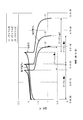
充放電試験の条件は、充電および放電を共に100mAの定電流で行い、充電終止電圧を2.2V、放電終止電圧を0.8Vに設定した。そして、充放電を三回(3サイクル)繰り返した。尚、充放電試験の開始前および期間中、不活性ガス供給管から窒素ガスを供給して、充放電セル並びに正極電解液タンクおよび負極電解液タンクの気相部分から酸素を追い出すと共に、電解液中の溶存酸素を追い出した。
充放電試験の結果を図2にグラフとして示す。当該グラフから、上記レドックスフロー型電池の各種性能、即ち、「充放電サイクル特性(可逆性)」、「クーロン効率」、「電圧効率」、「エネルギー効率」および「電解液の利用率」を算出した。また、1サイクル目の充放電において、充電から放電に切り替わるとき(電流が0mAのとき)の端子電圧を読み取って「起電力」とした。
上記「充放電サイクル特性(可逆性)」は、2サイクル目の充放電における放電時のクーロン量bと、3サイクル目の充放電における放電時のクーロン量eとを求め、式「(e/b)×100」(%)を用いて算出した。そして、算出した数値が80%以上である場合を「○」(繰り返しの充放電可能)、80%未満である場合を「×」(繰り返しの充放電不可能)と評価した。
上記「クーロン効率」は、2サイクル目の充放電における充電時のクーロン量a、および、2サイクル目の充放電における放電時のクーロン量bを求め、式「(b/a)×100」(%)を用いて算出した。
上記「電圧効率」は、2サイクル目の充放電における充電時の平均の端子電圧a、および、2サイクル目の充放電における放電時の平均の端子電圧bを求め、式「(b/a)×100」(%)を用いて算出した。
上記「エネルギー効率」は、式{「クーロン効率」×「電圧効率」}(%)を用いて算出した。
上記「電解液の利用率」は、正極側または負極側に供給される電解液の活物質の量(モル数)にファラデー定数(96500クーロン/モル)を乗じてクーロン量cを求めると共に、1サイクル目の充放電における放電時のクーロン量dを求め、式「(d/c)×100」(%)を用いて算出した。尚、いわゆる二液式で、正極側に供給される電解液の活物質の量と、負極側に供給される電解液の活物質の量とに差がある場合には、少ない量の方を採用して算出することとした。
その結果、「起電力」は1.9V、「充放電サイクル特性(可逆性)」は「○」、「クーロン効率」は80%、「電圧効率」は80%、「エネルギー効率」は64%、「電解液の利用率」は75%であった。従って、電力貯蔵電池として好適に使用することができることが判った。
〔実施例2〕
負極電解液を、下記方法によって調製した。即ち、先ず、蒸留水30mlに、0.08モル(40.0g)のCrK(SO4 )2 ・12H2 Oを加えて溶解させた。続いて、この水溶液に、0.09モル(26.3g)のEDTAと、0.18モル(7.2g)のNaOHとを少量ずつ添加して溶解させた。得られた水溶液を加熱して4時間、還流させた。還流操作中に、濃度が5.0モル/LのNaOH水溶液32mlを、少量ずつ添加した。そして、水溶液を冷却した後、0.2モル(27.2g)の酢酸ナトリウム・三水和物を加えて溶解させた。
負極電解液を、下記方法によって調製した。即ち、先ず、蒸留水30mlに、0.08モル(40.0g)のCrK(SO4 )2 ・12H2 Oを加えて溶解させた。続いて、この水溶液に、0.09モル(26.3g)のEDTAと、0.18モル(7.2g)のNaOHとを少量ずつ添加して溶解させた。得られた水溶液を加熱して4時間、還流させた。還流操作中に、濃度が5.0モル/LのNaOH水溶液32mlを、少量ずつ添加した。そして、水溶液を冷却した後、0.2モル(27.2g)の酢酸ナトリウム・三水和物を加えて溶解させた。
次いで、全量が200mlになるように蒸留水を加えた後、濃度が2.5モル/Lの希硫酸を滴下してpHを5.7に調節した。これにより、Cr-EDTA錯体の濃度が0.4モル/Lである水溶液を調製し、負極電解液とした。
一方、正極電解液を、下記方法によって調製した。即ち、先ず、蒸留水140mlに、0.08モル(13.5g)のMnSO4 ・H2 Oを加えて溶解させた。続いて、この水溶液に、0.08モル(33.3g)のEDTA・四ナトリウム塩・二水和物(EDTA(4Na)・2H2 O)を添加して溶解させた後、0.2モル(16.4g)の無水酢酸ナトリウムを加えて溶解させた。
次いで、全量が200mlになるように蒸留水を加えた後、濃度が1.0モル/Lの酢酸ナトリウム水溶液を滴下してpHを6.6に調節した。これにより、Mn-EDTA錯体の濃度が0.4モル/Lである水溶液を調製し、正極電解液とした。
上記正極電解液および負極電解液を用いて、実施例1で使用したレドックスフロー型電池の充放電試験を行った。充放電試験の条件は、充電および放電を共に50mAの定電流で行い、充電終止電圧を2.0V、放電終止電圧を0.8Vに設定した。尚、充放電試験における他の条件は、実施例1における充放電試験の条件と同一に設定した。
その結果、「起電力」は1.85V、「充放電サイクル特性(可逆性)」は「○」、「クーロン効率」は75%、「電圧効率」は85%、「エネルギー効率」は64%、「電解液の利用率」は55%であった。従って、電力貯蔵電池として好適に使用することができることが判った。
〔比較例1〕
正極電解液および負極電解液として、いわゆる一液式となるように、下記方法によって水溶液を調製した。即ち、実施例2と同様にして、Cr-EDTA錯体の濃度が0.4モル/Lであり、pHが5.7である水溶液を調製した。次に、Cr-EDTA錯体の濃度が0.1モル/Lとなり、酢酸ナトリウムの濃度が1.0モル/Lとなるように、上記水溶液に無水酢酸ナトリウムおよび蒸留水を加えた後、濃度が2.5モル/Lの希硫酸を滴下してpHを5.5に調節した。これにより、Cr-EDTA錯体の濃度が0.1モル/Lである一液式の電解液を調製した。
正極電解液および負極電解液として、いわゆる一液式となるように、下記方法によって水溶液を調製した。即ち、実施例2と同様にして、Cr-EDTA錯体の濃度が0.4モル/Lであり、pHが5.7である水溶液を調製した。次に、Cr-EDTA錯体の濃度が0.1モル/Lとなり、酢酸ナトリウムの濃度が1.0モル/Lとなるように、上記水溶液に無水酢酸ナトリウムおよび蒸留水を加えた後、濃度が2.5モル/Lの希硫酸を滴下してpHを5.5に調節した。これにより、Cr-EDTA錯体の濃度が0.1モル/Lである一液式の電解液を調製した。
上記電解液を用いて、実施例1で使用したレドックスフロー型電池の充放電試験を行った。充放電試験の条件は、充電および放電を共に50mAの定電流で行い、充電終止電圧を2.4V、放電終止電圧を0.8Vに設定した。尚、充放電試験における他の条件は、実施例1における充放電試験の条件と同一に設定した。
その結果、「起電力」は2.05V、「充放電サイクル特性(可逆性)」は「×」、「クーロン効率」は50%、「電圧効率」は60%、「エネルギー効率」は30%、「電解液の利用率」は10%であり、電力貯蔵電池として不適であることが判った。
〔比較例2〕
実施例2と同様にして、Cr-EDTA錯体の濃度が0.4モル/Lである水溶液(pHが5.7)を調製し、負極電解液とした。
実施例2と同様にして、Cr-EDTA錯体の濃度が0.4モル/Lである水溶液(pHが5.7)を調製し、負極電解液とした。
一方、正極電解液を、下記方法によって調製した。即ち、先ず、蒸留水120mlに、0.08モル(22.2g)のFeSO4 ・7H2 Oを加えて溶解させた。続いて、この水溶液に、0.08モル(29.8g)のEDTA・二ナトリウム塩・二水和物(EDTA(2Na)・2H2 O)を添加して溶解させた後、0.2モル(16.4g)の無水酢酸ナトリウムを加えて溶解させた。
次いで、全量が200mlになるように蒸留水を加えた後、濃度が1.0モル/Lの酢酸ナトリウム水溶液を滴下してpHを4.5に調節した。これにより、Fe-EDTA錯体の濃度が0.4モル/Lである水溶液を調製し、正極電解液とした。
上記両電解液を用いて、実施例1で使用したレドックスフロー型電池の充放電試験を行った。充放電試験の条件は、充電および放電を共に50mAの定電流で行い、充電終止電圧を1.6V、放電終止電圧を0.8Vに設定した。尚、充放電試験における他の条件は、実施例1における充放電試験の条件と同一に設定した。
その結果、「起電力」は1.25V、「充放電サイクル特性(可逆性)」は「×」、「クーロン効率」は65%、「電圧効率」は90%、「エネルギー効率」は59%、「電解液の利用率」は25%であり、電力貯蔵電池として不適であることが判った。
〔比較例3〕
実施例2と同様にして、Cr-EDTA錯体の濃度が0.4モル/Lである水溶液(pHが5.7)を調製した。一方、比較例2と同様にして、Fe-EDTA錯体の濃度が0.4モル/Lである水溶液(pHが4.5)を調製した。そして、両水溶液を1:1で混合することにより、Cr-EDTA錯体の濃度が0.2モル/Lであり、Fe-EDTA錯体の濃度が0.2モル/Lであるプレミックス方式の電解液を調製した。
実施例2と同様にして、Cr-EDTA錯体の濃度が0.4モル/Lである水溶液(pHが5.7)を調製した。一方、比較例2と同様にして、Fe-EDTA錯体の濃度が0.4モル/Lである水溶液(pHが4.5)を調製した。そして、両水溶液を1:1で混合することにより、Cr-EDTA錯体の濃度が0.2モル/Lであり、Fe-EDTA錯体の濃度が0.2モル/Lであるプレミックス方式の電解液を調製した。
上記電解液を用いて、実施例1で使用したレドックスフロー型電池の充放電試験を行った。その結果、50mAの定電流で充電を行い、充電終止電圧を1.3Vにすることができたものの、放電を行うことはできなかった。従って、電力貯蔵電池として不適であることが判った。
〔比較例4〕
実施例2と同様にして、Cr-EDTA錯体の濃度が0.4モル/Lである水溶液(pHが5.7)を調製し、負極電解液とした。一方、正極電解液を、下記方法によって調製した。即ち、蒸留水90mlに、0.08モル(22.2g)のFeSO4 ・7H2 Oを加えて溶解させた後、濃度が2.5モル/Lの希硫酸80mlを加えた。次に、上記水溶液を蒸留水で希釈して、FeSO4 の濃度が0.4モル/Lである水溶液を調製し、正極電解液とした。
実施例2と同様にして、Cr-EDTA錯体の濃度が0.4モル/Lである水溶液(pHが5.7)を調製し、負極電解液とした。一方、正極電解液を、下記方法によって調製した。即ち、蒸留水90mlに、0.08モル(22.2g)のFeSO4 ・7H2 Oを加えて溶解させた後、濃度が2.5モル/Lの希硫酸80mlを加えた。次に、上記水溶液を蒸留水で希釈して、FeSO4 の濃度が0.4モル/Lである水溶液を調製し、正極電解液とした。
上記両電解液を用いて、実施例1で使用したレドックスフロー型電池の充放電試験を行った。その結果、50mAの定電流で充電を行い、充電終止電圧を1.3Vにすることができたものの、放電を行うことはできなかった。従って、電力貯蔵電池として不適であることが判った。
〔比較例5〕
実施例2と同様にして、Cr-EDTA錯体の濃度が0.4モル/Lである水溶液(pHが5.7)を調製し、負極電解液とした。一方、正極電解液を、下記方法によって調製した。即ち、蒸留水140mlに、0.2モル(20.6g)のNaBrを加えて溶解させた後、0.2モル(16.4g)の無水酢酸ナトリウムを加えて溶解させた。次いで、全量が200mlになるように蒸留水を加えた。これにより、NaBrの濃度が1.0モル/Lである水溶液を調製し、正極電解液とした。
実施例2と同様にして、Cr-EDTA錯体の濃度が0.4モル/Lである水溶液(pHが5.7)を調製し、負極電解液とした。一方、正極電解液を、下記方法によって調製した。即ち、蒸留水140mlに、0.2モル(20.6g)のNaBrを加えて溶解させた後、0.2モル(16.4g)の無水酢酸ナトリウムを加えて溶解させた。次いで、全量が200mlになるように蒸留水を加えた。これにより、NaBrの濃度が1.0モル/Lである水溶液を調製し、正極電解液とした。
上記両電解液を用いて、実施例1で使用したレドックスフロー型電池の充放電試験を行った。充放電試験の条件は、充電および放電を共に50mAの定電流で行い、充電終止電圧を2.3V、放電終止電圧を0.8Vに設定した。尚、充放電試験における他の条件は、実施例1における充放電試験の条件と同一に設定した。
その結果、「起電力」は2.20V、「充放電サイクル特性(可逆性)」は「×」、「クーロン効率」は55%、「電圧効率」は70%、「エネルギー効率」は39%、「電解液の利用率」は15%であり、電力貯蔵電池として不適であることが判った。
〔比較例6〕
実施例2と同様にして、Cr-EDTA錯体の濃度が0.4モル/Lである水溶液(pHが5.7)を調製し、負極電解液とした。一方、正極電解液を、下記方法によって調製した。即ち、蒸留水130mlに、0.2モル(42.0g)の臭化テトラエチルアンモニウム(N(C2 H5 )4 + ・Br- )を加えて溶解させた後、0.2モル(16.4g)の無水酢酸ナトリウムを加えて溶解させた。次いで、全量が200mlになるように蒸留水を加えた。これにより、臭化テトラエチルアンモニウムの濃度が1.0モル/Lである水溶液を調製し、正極電解液とした。
実施例2と同様にして、Cr-EDTA錯体の濃度が0.4モル/Lである水溶液(pHが5.7)を調製し、負極電解液とした。一方、正極電解液を、下記方法によって調製した。即ち、蒸留水130mlに、0.2モル(42.0g)の臭化テトラエチルアンモニウム(N(C2 H5 )4 + ・Br- )を加えて溶解させた後、0.2モル(16.4g)の無水酢酸ナトリウムを加えて溶解させた。次いで、全量が200mlになるように蒸留水を加えた。これにより、臭化テトラエチルアンモニウムの濃度が1.0モル/Lである水溶液を調製し、正極電解液とした。
上記両電解液を用いて、実施例1で使用したレドックスフロー型電池の充放電試験を行った。充放電試験の条件は、充電および放電を共に50mAの定電流で行い、充電終止電圧を2.4V、放電終止電圧を0.8Vに設定した。尚、充放電試験における他の条件は、実施例1における充放電試験の条件と同一に設定した。
その結果、「起電力」は2.15V、「充放電サイクル特性(可逆性)」は「×」、「クーロン効率」は40%、「電圧効率」は80%、「エネルギー効率」は32%、「電解液の利用率」は10%であり、電力貯蔵電池として不適であることが判った。
〔比較例7〕
実施例1と同様にして、Cr-EDTA錯体の濃度が0.57モル/Lである水溶液140ml(pHが5.7)を調製した。次に、Cr-EDTA錯体の濃度が0.4モル/Lとなるように上記水溶液を蒸留水で希釈すると共に、0.2モル(20.6g)のNaBrを加えて溶解させた。これにより、Cr-EDTA錯体の濃度が0.4モル/Lであり、NaBrの濃度が1.0モル/Lである一液式の電解液を調製した。
実施例1と同様にして、Cr-EDTA錯体の濃度が0.57モル/Lである水溶液140ml(pHが5.7)を調製した。次に、Cr-EDTA錯体の濃度が0.4モル/Lとなるように上記水溶液を蒸留水で希釈すると共に、0.2モル(20.6g)のNaBrを加えて溶解させた。これにより、Cr-EDTA錯体の濃度が0.4モル/Lであり、NaBrの濃度が1.0モル/Lである一液式の電解液を調製した。
上記電解液を用いて、実施例1で使用したレドックスフロー型電池の充放電試験を行った。充放電試験の条件は、充電および放電を共に50mAの定電流で行い、充電終止電圧を2.3V、放電終止電圧を0.8Vに設定した。尚、充放電試験における他の条件は、実施例1における充放電試験の条件と同一に設定した。
その結果、「起電力」は2.20V、「充放電サイクル特性(可逆性)」は「×」、「クーロン効率」は45%、「電圧効率」は90%、「エネルギー効率」は41%、「電解液の利用率」は15%であり、電力貯蔵電池として不適であることが判った。
〔実施例3〕
正極電解液および負極電解液として、いわゆるプレミックス方式となるように、下記方法によって水溶液を調製した。即ち、先ず、実施例1と同様にして、Cr-EDTA錯体の濃度が0.57モル/Lである水溶液140ml(pHが5.7)を調製した。次に、調製した上記水溶液に、0.1モル(16.9g)のMnSO4 ・H2 Oを加えて溶解させた。続いて、この水溶液に、0.1モル(41.6g)のEDTA・四ナトリウム塩・二水和物(EDTA(4Na)・2H2 O)を添加して溶解させた。次いで、全量が250mlになるように蒸留水を加えた。これにより、Mn-EDTA錯体の濃度が0.4モル/Lであり、Cr-EDTA錯体の濃度が0.32モル/Lである水溶液を調製した。
正極電解液および負極電解液として、いわゆるプレミックス方式となるように、下記方法によって水溶液を調製した。即ち、先ず、実施例1と同様にして、Cr-EDTA錯体の濃度が0.57モル/Lである水溶液140ml(pHが5.7)を調製した。次に、調製した上記水溶液に、0.1モル(16.9g)のMnSO4 ・H2 Oを加えて溶解させた。続いて、この水溶液に、0.1モル(41.6g)のEDTA・四ナトリウム塩・二水和物(EDTA(4Na)・2H2 O)を添加して溶解させた。次いで、全量が250mlになるように蒸留水を加えた。これにより、Mn-EDTA錯体の濃度が0.4モル/Lであり、Cr-EDTA錯体の濃度が0.32モル/Lである水溶液を調製した。
上記水溶液をプレミックス方式の電解液として用いて、実施例1で使用したレドックスフロー型電池の充放電試験を行った。充放電試験の条件は、充電および放電を共に100mAの定電流で行い、充電終止電圧を2.2V、放電終止電圧を0.8Vに設定した。尚、充放電試験における他の条件は、実施例1における充放電試験の条件と同一に設定した。
その結果、「起電力」は2.0V、「充放電サイクル特性(可逆性)」は「○」、「クーロン効率」は68%、「電圧効率」は72%、「エネルギー効率」は49%、「電解液の利用率」は59%であった。従って、電力貯蔵電池として好適に使用することができることが判った。
〔実施例4〕
正極電解液および負極電解液として、いわゆるプレミックス方式となるように、下記方法によって水溶液を調製した。即ち、先ず、実施例1と同様にして、Cr-EDTA錯体の濃度が0.57モル/Lである水溶液105ml(pHが5.7)を調製した。次に、調製した上記水溶液に、0.2モル(33.8g)のMnSO4 ・H2 Oを加えて溶解させた。続いて、この水溶液に、0.2モル(83.2g)のEDTA・四ナトリウム塩・二水和物(EDTA(4Na)・2H2 O)を添加して溶解させた。次いで、全量が250mlになるように蒸留水を加えた。これにより、Mn-EDTA錯体の濃度が0.8モル/Lであり、Cr-EDTA錯体の濃度が0.24モル/Lである水溶液を調製した。
正極電解液および負極電解液として、いわゆるプレミックス方式となるように、下記方法によって水溶液を調製した。即ち、先ず、実施例1と同様にして、Cr-EDTA錯体の濃度が0.57モル/Lである水溶液105ml(pHが5.7)を調製した。次に、調製した上記水溶液に、0.2モル(33.8g)のMnSO4 ・H2 Oを加えて溶解させた。続いて、この水溶液に、0.2モル(83.2g)のEDTA・四ナトリウム塩・二水和物(EDTA(4Na)・2H2 O)を添加して溶解させた。次いで、全量が250mlになるように蒸留水を加えた。これにより、Mn-EDTA錯体の濃度が0.8モル/Lであり、Cr-EDTA錯体の濃度が0.24モル/Lである水溶液を調製した。
上記水溶液をプレミックス方式の電解液として用いて、実施例1で使用したレドックスフロー型電池の充放電試験を行った。充放電試験の条件は、充電および放電を共に100mAの定電流で行い、充電終止電圧を2.2V、放電終止電圧を0.8Vに設定した。尚、充放電試験における他の条件は、実施例1における充放電試験の条件と同一に設定した。
その結果、「起電力」は2.0V、「充放電サイクル特性(可逆性)」は「○」、「クーロン効率」は76%、「電圧効率」は70%、「エネルギー効率」は53%、「電解液の利用率」は82%であった。従って、電力貯蔵電池として好適に使用することができることが判った。
〔実施例5〕
正極電解液および負極電解液として、いわゆるプレミックス方式となるように、下記方法によって水溶液を調製した。即ち、実施例3と同様にして、Mn-EDTA錯体の濃度が0.4モル/Lであり、Cr-EDTA錯体の濃度が0.32モル/Lである水溶液を調製した。その後、この水溶液に、濃度が2.5モル/Lの希硫酸を滴下してpHを3.0に調節することにより、プレミックス方式の電解液を調製した。
正極電解液および負極電解液として、いわゆるプレミックス方式となるように、下記方法によって水溶液を調製した。即ち、実施例3と同様にして、Mn-EDTA錯体の濃度が0.4モル/Lであり、Cr-EDTA錯体の濃度が0.32モル/Lである水溶液を調製した。その後、この水溶液に、濃度が2.5モル/Lの希硫酸を滴下してpHを3.0に調節することにより、プレミックス方式の電解液を調製した。
上記電解液を用いて、実施例1で使用したレドックスフロー型電池の充放電試験を行った。充放電試験の条件は、充電および放電を共に100mAの定電流で行い、充電終止電圧を2.4V、放電終止電圧を0.8Vに設定した。尚、充放電試験における他の条件は、実施例1における充放電試験の条件と同一に設定した。
その結果、「起電力」は2.0V、「充放電サイクル特性(可逆性)」は「○」、「クーロン効率」は66%、「電圧効率」は64%、「エネルギー効率」は42%、「電解液の利用率」は29%であった。従って、電力貯蔵電池として好適に使用することができることが判った。
〔実施例6〕
pHを4.5に調節した以外は実施例5と同様の操作を行うことにより、プレミックス方式の電解液を調製した。
pHを4.5に調節した以外は実施例5と同様の操作を行うことにより、プレミックス方式の電解液を調製した。
上記電解液を用いて、実施例1で使用したレドックスフロー型電池の充放電試験を行った。充放電試験の条件は、充電および放電を共に100mAの定電流で行い、充電終止電圧を2.2V、放電終止電圧を0.8Vに設定した。尚、充放電試験における他の条件は、実施例1における充放電試験の条件と同一に設定した。
その結果、「起電力」は2.0V、「充放電サイクル特性(可逆性)」は「○」、「クーロン効率」は74%、「電圧効率」は70%、「エネルギー効率」は52%、「電解液の利用率」は39%であった。従って、電力貯蔵電池として好適に使用することができることが判った。
〔実施例7〕
正極電解液および負極電解液として、いわゆるプレミックス方式となるように、下記方法によって水溶液を調製した。即ち、実施例3と同様にして、Mn-EDTA錯体の濃度が0.4モル/Lであり、Cr-EDTA錯体の濃度が0.32モル/Lである水溶液を調製した。その後、この水溶液に、濃度が5.0モル/LのNaOH水溶液を滴下してpHを6.0に調節することにより、プレミックス方式の電解液を調製した。
正極電解液および負極電解液として、いわゆるプレミックス方式となるように、下記方法によって水溶液を調製した。即ち、実施例3と同様にして、Mn-EDTA錯体の濃度が0.4モル/Lであり、Cr-EDTA錯体の濃度が0.32モル/Lである水溶液を調製した。その後、この水溶液に、濃度が5.0モル/LのNaOH水溶液を滴下してpHを6.0に調節することにより、プレミックス方式の電解液を調製した。
上記電解液を用いて、実施例1で使用したレドックスフロー型電池の充放電試験を行った。充放電試験の条件は、充電および放電を共に100mAの定電流で行い、充電終止電圧を2.2V、放電終止電圧を0.8Vに設定した。尚、充放電試験における他の条件は、実施例1における充放電試験の条件と同一に設定した。
その結果、「起電力」は2.0V、「充放電サイクル特性(可逆性)」は「○」、「クーロン効率」は74%、「電圧効率」は74%、「エネルギー効率」は55%、「電解液の利用率」は60%であった。従って、電力貯蔵電池として好適に使用することができることが判った。
〔実施例8〕
pHを8.0に調節した以外は実施例7と同様の操作を行うことにより、プレミックス方式の電解液を調製した。
pHを8.0に調節した以外は実施例7と同様の操作を行うことにより、プレミックス方式の電解液を調製した。
上記電解液を用いて、実施例1で使用したレドックスフロー型電池の充放電試験を行った。充放電試験の条件は、充電および放電を共に100mAの定電流で行い、充電終止電圧を2.3V、放電終止電圧を0.8Vに設定した。尚、充放電試験における他の条件は、実施例1における充放電試験の条件と同一に設定した。
その結果、「起電力」は2.0V、「充放電サイクル特性(可逆性)」は「○」、「クーロン効率」は70%、「電圧効率」は68%、「エネルギー効率」は48%、「電解液の利用率」は43%であった。従って、電力貯蔵電池として好適に使用することができることが判った。
本発明は、上述した各実施形態に限定されるものではなく、請求項に示した範囲で種々の変更が可能であり、異なる実施形態にそれぞれ開示された技術的手段を適宜組み合わせて得られる実施形態についても、本発明の技術的範囲に含まれる。
本発明に係る電力貯蔵電池によれば、取り扱い性に優れると共に、充放電サイクル特性(可逆性)やエネルギー効率、クーロン効率等の各種性能に優れた電力貯蔵電池を、比較的安価に提供することができるという効果を奏する。
それゆえ、本発明に係る電力貯蔵電池は、電力会社のみならず、電力貯蔵が必要な各種産業において広範に利用され得る。
1 レドックスフロー型電池(電力貯蔵電池)
2 充放電セル(電池容器)
2a 正極側セル
2b 負極側セル
3 正極電解液タンク
4 負極電解液タンク
10 充放電装置
11 隔膜
12 集電板
13 正極
14 集電板
15 負極
2 充放電セル(電池容器)
2a 正極側セル
2b 負極側セル
3 正極電解液タンク
4 負極電解液タンク
10 充放電装置
11 隔膜
12 集電板
13 正極
14 集電板
15 負極
Claims (6)
- 正極電解液および負極電解液のpHが3~8の範囲内であり、正極電解液がMnのアミノポリカルボン酸キレート物を含む水溶液であることを特徴とする電力貯蔵電池。
- 正極電解液がMn-EDTA錯体を含む水溶液であることを特徴とする請求項1に記載の電力貯蔵電池。
- 上記水溶液におけるMn-EDTA錯体の濃度が0.2モル/L以上、1.0モル/L以下であることを特徴とする請求項2に記載の電力貯蔵電池。
- 負極電解液がCr-EDTA錯体を含む水溶液であることを特徴とする請求項1に記載の電力貯蔵電池。
- 正極電解液および負極電解液が、Mn-EDTA錯体およびCr-EDTA錯体を含む水溶液であることを特徴とする請求項1に記載の電力貯蔵電池。
- レドックスフロー型電池であることを特徴とする請求項1に記載の電力貯蔵電池。
Priority Applications (2)
| Application Number | Priority Date | Filing Date | Title |
|---|---|---|---|
| PCT/JP2011/054798 WO2012117543A1 (ja) | 2011-03-02 | 2011-03-02 | 電力貯蔵電池 |
| PCT/JP2011/070367 WO2012117594A1 (ja) | 2011-03-02 | 2011-09-07 | 電力貯蔵電池 |
Applications Claiming Priority (1)
| Application Number | Priority Date | Filing Date | Title |
|---|---|---|---|
| PCT/JP2011/054798 WO2012117543A1 (ja) | 2011-03-02 | 2011-03-02 | 電力貯蔵電池 |
Publications (1)
| Publication Number | Publication Date |
|---|---|
| WO2012117543A1 true WO2012117543A1 (ja) | 2012-09-07 |
Family
ID=46757503
Family Applications (2)
| Application Number | Title | Priority Date | Filing Date |
|---|---|---|---|
| PCT/JP2011/054798 Ceased WO2012117543A1 (ja) | 2011-03-02 | 2011-03-02 | 電力貯蔵電池 |
| PCT/JP2011/070367 Ceased WO2012117594A1 (ja) | 2011-03-02 | 2011-09-07 | 電力貯蔵電池 |
Family Applications After (1)
| Application Number | Title | Priority Date | Filing Date |
|---|---|---|---|
| PCT/JP2011/070367 Ceased WO2012117594A1 (ja) | 2011-03-02 | 2011-09-07 | 電力貯蔵電池 |
Country Status (1)
| Country | Link |
|---|---|
| WO (2) | WO2012117543A1 (ja) |
Cited By (12)
| Publication number | Priority date | Publication date | Assignee | Title |
|---|---|---|---|---|
| US20140028261A1 (en) * | 2012-07-27 | 2014-01-30 | Sun Catalytic Corporation | Electrochemical Energy Storage Systems and Methods Featuring Large Negative Half-Cell Potentials |
| WO2014102910A1 (ja) * | 2012-12-25 | 2014-07-03 | 日新電機 株式会社 | 電力貯蔵電池 |
| WO2014102898A1 (ja) * | 2012-12-25 | 2014-07-03 | 日新電機 株式会社 | 電力貯蔵電池 |
| WO2014147778A1 (ja) * | 2013-03-21 | 2014-09-25 | 日新電機 株式会社 | 電力貯蔵電池 |
| JP2015065157A (ja) * | 2013-08-26 | 2015-04-09 | 一般社団法人新エネルギー支援機構 | 電力エネルギーの輸送システム |
| EP3174149A4 (en) * | 2014-07-25 | 2017-07-12 | Sumitomo Electric Industries, Ltd. | Electrolytic solution circulation type battery |
| US9768463B2 (en) | 2012-07-27 | 2017-09-19 | Lockheed Martin Advanced Energy Storage, Llc | Aqueous redox flow batteries comprising metal ligand coordination compounds |
| US9865893B2 (en) | 2012-07-27 | 2018-01-09 | Lockheed Martin Advanced Energy Storage, Llc | Electrochemical energy storage systems and methods featuring optimal membrane systems |
| US9899694B2 (en) | 2012-07-27 | 2018-02-20 | Lockheed Martin Advanced Energy Storage, Llc | Electrochemical energy storage systems and methods featuring high open circuit potential |
| CN114899466A (zh) * | 2022-06-21 | 2022-08-12 | 中山大学 | 一种锰铁液流电池及其制造方法 |
| WO2023227226A1 (en) * | 2022-05-27 | 2023-11-30 | Green Energy Storage S.R.L. | Redox flow battery |
| CN120709391A (zh) * | 2025-08-27 | 2025-09-26 | 杭州德海艾科能源科技有限公司 | 一种尖晶石纳米纤维复合石墨毡电极及其制备方法 |
Families Citing this family (5)
| Publication number | Priority date | Publication date | Assignee | Title |
|---|---|---|---|---|
| JP2016177868A (ja) * | 2013-08-07 | 2016-10-06 | 住友電気工業株式会社 | レドックスフロー電池 |
| CN107134582B (zh) * | 2017-06-05 | 2021-04-06 | 上海骐杰碳素材料有限公司 | 一种高活性电极材料及其改性方法 |
| EP3669390B1 (en) | 2017-08-17 | 2025-05-28 | The Trustees of Columbia University in the City of New York | Redox flow batteries and compounds for battery application |
| AU2020240320A1 (en) | 2019-03-20 | 2021-11-11 | The Regents Of The University Of Colorado, A Body Corporate | Electrochemical storage devices comprising chelated metals |
| CN114243073B (zh) * | 2021-12-09 | 2023-11-28 | 大连融科储能集团股份有限公司 | 一种低温下稳定运行和存储的盐酸电解液、其制备方法及应用 |
Citations (6)
| Publication number | Priority date | Publication date | Assignee | Title |
|---|---|---|---|---|
| JPS579073A (en) * | 1980-06-17 | 1982-01-18 | Agency Of Ind Science & Technol | Bedox battery |
| JPS579072A (en) * | 1980-06-17 | 1982-01-18 | Agency Of Ind Science & Technol | Redox battery |
| JPS611270U (ja) * | 1984-06-11 | 1986-01-07 | 住友電気工業株式会社 | 電池 |
| JPS6122574A (ja) * | 1984-07-09 | 1986-01-31 | Sumitomo Electric Ind Ltd | 電池 |
| JP2002193621A (ja) * | 2000-12-26 | 2002-07-10 | Nippon Chem Ind Co Ltd | 変性バナジウム化合物、その製造方法、レドックスフロー型電池用電解液組成物及びレドックスフロー型電池用電解液の製造方法 |
| JP2009231230A (ja) * | 2008-03-25 | 2009-10-08 | Kurita Water Ind Ltd | 微生物発電方法および装置 |
Family Cites Families (2)
| Publication number | Priority date | Publication date | Assignee | Title |
|---|---|---|---|---|
| JPS5834911B2 (ja) * | 1979-09-14 | 1983-07-29 | 工業技術院長 | レドツクス電池 |
| JPS6215770A (ja) * | 1985-07-11 | 1987-01-24 | Yamaguchi Univ | レドックス二次電池 |
-
2011
- 2011-03-02 WO PCT/JP2011/054798 patent/WO2012117543A1/ja not_active Ceased
- 2011-09-07 WO PCT/JP2011/070367 patent/WO2012117594A1/ja not_active Ceased
Patent Citations (6)
| Publication number | Priority date | Publication date | Assignee | Title |
|---|---|---|---|---|
| JPS579073A (en) * | 1980-06-17 | 1982-01-18 | Agency Of Ind Science & Technol | Bedox battery |
| JPS579072A (en) * | 1980-06-17 | 1982-01-18 | Agency Of Ind Science & Technol | Redox battery |
| JPS611270U (ja) * | 1984-06-11 | 1986-01-07 | 住友電気工業株式会社 | 電池 |
| JPS6122574A (ja) * | 1984-07-09 | 1986-01-31 | Sumitomo Electric Ind Ltd | 電池 |
| JP2002193621A (ja) * | 2000-12-26 | 2002-07-10 | Nippon Chem Ind Co Ltd | 変性バナジウム化合物、その製造方法、レドックスフロー型電池用電解液組成物及びレドックスフロー型電池用電解液の製造方法 |
| JP2009231230A (ja) * | 2008-03-25 | 2009-10-08 | Kurita Water Ind Ltd | 微生物発電方法および装置 |
Cited By (25)
| Publication number | Priority date | Publication date | Assignee | Title |
|---|---|---|---|---|
| US9559374B2 (en) * | 2012-07-27 | 2017-01-31 | Lockheed Martin Advanced Energy Storage, Llc | Electrochemical energy storage systems and methods featuring large negative half-cell potentials |
| US10707513B2 (en) | 2012-07-27 | 2020-07-07 | Lockheed Martin Energy, Llc | Aqueous redox flow batteries comprising metal ligand coordination compounds |
| US10651489B2 (en) | 2012-07-27 | 2020-05-12 | Lockheed Martin Energy, Llc | Electrochemical energy storage systems and methods featuring optimal membrane systems |
| US10483581B2 (en) | 2012-07-27 | 2019-11-19 | Lockheed Martin Energy, Llc | Electrochemical energy storage systems and methods featuring large negative half-cell potentials |
| US9899694B2 (en) | 2012-07-27 | 2018-02-20 | Lockheed Martin Advanced Energy Storage, Llc | Electrochemical energy storage systems and methods featuring high open circuit potential |
| US9865893B2 (en) | 2012-07-27 | 2018-01-09 | Lockheed Martin Advanced Energy Storage, Llc | Electrochemical energy storage systems and methods featuring optimal membrane systems |
| US20140028261A1 (en) * | 2012-07-27 | 2014-01-30 | Sun Catalytic Corporation | Electrochemical Energy Storage Systems and Methods Featuring Large Negative Half-Cell Potentials |
| US9768463B2 (en) | 2012-07-27 | 2017-09-19 | Lockheed Martin Advanced Energy Storage, Llc | Aqueous redox flow batteries comprising metal ligand coordination compounds |
| US9515345B2 (en) | 2012-12-25 | 2016-12-06 | Nissin Electric Co., Ltd. | Electricity-storage battery |
| WO2014102898A1 (ja) * | 2012-12-25 | 2014-07-03 | 日新電機 株式会社 | 電力貯蔵電池 |
| JPWO2014102910A1 (ja) * | 2012-12-25 | 2017-01-12 | 日新電機株式会社 | 電力貯蔵電池及びその製造方法 |
| WO2014102910A1 (ja) * | 2012-12-25 | 2014-07-03 | 日新電機 株式会社 | 電力貯蔵電池 |
| JPWO2014102898A1 (ja) * | 2012-12-25 | 2017-01-12 | 日新電機株式会社 | 電力貯蔵電池及びその製造方法 |
| US9774054B2 (en) | 2013-03-21 | 2017-09-26 | Nissin Electric Co., Ltd. | Electricity storage battery |
| JP6065351B2 (ja) * | 2013-03-21 | 2017-01-25 | 日新電機株式会社 | 電力貯蔵電池 |
| WO2014147778A1 (ja) * | 2013-03-21 | 2014-09-25 | 日新電機 株式会社 | 電力貯蔵電池 |
| CN105493329B (zh) * | 2013-08-26 | 2017-03-01 | 一般社团法人新能源支援机构 | 电力能量的输送系统 |
| CN105493329A (zh) * | 2013-08-26 | 2016-04-13 | 一般社团法人新能源支援机构 | 电力能量的输送系统 |
| JP2015065157A (ja) * | 2013-08-26 | 2015-04-09 | 一般社団法人新エネルギー支援機構 | 電力エネルギーの輸送システム |
| US10396372B2 (en) | 2014-07-25 | 2019-08-27 | Sumitomo Electric Industries, Ltd. | Electrolytic solution circulation type battery |
| EP3174149A4 (en) * | 2014-07-25 | 2017-07-12 | Sumitomo Electric Industries, Ltd. | Electrolytic solution circulation type battery |
| WO2023227226A1 (en) * | 2022-05-27 | 2023-11-30 | Green Energy Storage S.R.L. | Redox flow battery |
| CN114899466A (zh) * | 2022-06-21 | 2022-08-12 | 中山大学 | 一种锰铁液流电池及其制造方法 |
| CN114899466B (zh) * | 2022-06-21 | 2023-02-21 | 中山大学 | 一种锰铁液流电池及其制造方法 |
| CN120709391A (zh) * | 2025-08-27 | 2025-09-26 | 杭州德海艾科能源科技有限公司 | 一种尖晶石纳米纤维复合石墨毡电极及其制备方法 |
Also Published As
| Publication number | Publication date |
|---|---|
| WO2012117594A1 (ja) | 2012-09-07 |
Similar Documents
| Publication | Publication Date | Title |
|---|---|---|
| WO2012117594A1 (ja) | 電力貯蔵電池 | |
| CN111354965B (zh) | 一种大规模储能低成本中性液流电池的制备方法 | |
| CN118016944B (zh) | 一种水系铁铈液流电池 | |
| CN104995767B (zh) | 包含金属配体配位化合物的含水氧化还原液流电池 | |
| CN101997129B (zh) | 一种液流电池 | |
| JP5768933B2 (ja) | 電力貯蔵電池 | |
| US9960445B2 (en) | Redox flow battery that uses complexes of cobalt and iron with amino-alcohol ligands in alkaline electrolytes to store electrical energy | |
| JP7035181B2 (ja) | 亜鉛-ヨウ化物フロー電池 | |
| CN112786938B (zh) | 具有双溶解沉积反应的酸碱混合高电压水系锌电池和锌液流电池 | |
| CN108475802A (zh) | 再生燃料电池 | |
| JP2008166248A (ja) | 水素貯蔵タンクを有する燃料電池 | |
| CN105680082A (zh) | 一种长寿命锌溴液流电池结构及其电解液 | |
| WO2018103518A1 (zh) | 一种中性锌铁液流电池 | |
| CN113067025A (zh) | 一种碱性锌铁液流电池电解液在线恢复方法 | |
| CN103872370B (zh) | 液流电池 | |
| CN113013460B (zh) | 一种碱性锌铁液流电池用负极电解液及锌铁液流电池 | |
| CN201514973U (zh) | 一种液流电池 | |
| CN102544563A (zh) | 一种锌沉积型液流储能电池系统及其运行方式 | |
| CN117219821A (zh) | 一种铬-稀土液流电池 | |
| CN114824369B (zh) | 一种全铁液流电池的电解液再平衡方法 | |
| CN103794813B (zh) | 铕铈液流电池 | |
| CN104335405A (zh) | 蓄电池 | |
| CN119324241B (zh) | 一种新型铕铈液流电池电解液及制备方法 | |
| CN108123174A (zh) | 一种碱性锌铁液流电池用正极电解液及应用 | |
| JP6220462B2 (ja) | 化学流動電池の運転方法 |
Legal Events
| Date | Code | Title | Description |
|---|---|---|---|
| 121 | Ep: the epo has been informed by wipo that ep was designated in this application |
Ref document number: 11860051 Country of ref document: EP Kind code of ref document: A1 |
|
| NENP | Non-entry into the national phase |
Ref country code: DE |
|
| 122 | Ep: pct application non-entry in european phase |
Ref document number: 11860051 Country of ref document: EP Kind code of ref document: A1 |
|
| NENP | Non-entry into the national phase |
Ref country code: JP |