WO2012115037A1 - 可撓性基板の搬送装置及び表示デバイス又は電子回路の製造システム - Google Patents
可撓性基板の搬送装置及び表示デバイス又は電子回路の製造システム Download PDFInfo
- Publication number
- WO2012115037A1 WO2012115037A1 PCT/JP2012/053961 JP2012053961W WO2012115037A1 WO 2012115037 A1 WO2012115037 A1 WO 2012115037A1 JP 2012053961 W JP2012053961 W JP 2012053961W WO 2012115037 A1 WO2012115037 A1 WO 2012115037A1
- Authority
- WO
- WIPO (PCT)
- Prior art keywords
- rail
- substrate
- roller
- unit
- supply roller
- Prior art date
- Legal status (The legal status is an assumption and is not a legal conclusion. Google has not performed a legal analysis and makes no representation as to the accuracy of the status listed.)
- Ceased
Links
Images





Classifications
-
- B—PERFORMING OPERATIONS; TRANSPORTING
- B65—CONVEYING; PACKING; STORING; HANDLING THIN OR FILAMENTARY MATERIAL
- B65H—HANDLING THIN OR FILAMENTARY MATERIAL, e.g. SHEETS, WEBS, CABLES
- B65H23/00—Registering, tensioning, smoothing or guiding webs
- B65H23/04—Registering, tensioning, smoothing or guiding webs longitudinally
-
- B—PERFORMING OPERATIONS; TRANSPORTING
- B65—CONVEYING; PACKING; STORING; HANDLING THIN OR FILAMENTARY MATERIAL
- B65H—HANDLING THIN OR FILAMENTARY MATERIAL, e.g. SHEETS, WEBS, CABLES
- B65H18/00—Winding webs
- B65H18/08—Web-winding mechanisms
- B65H18/10—Mechanisms in which power is applied to web-roll spindle
- B65H18/103—Reel-to-reel type web winding and unwinding mechanisms
-
- B—PERFORMING OPERATIONS; TRANSPORTING
- B65—CONVEYING; PACKING; STORING; HANDLING THIN OR FILAMENTARY MATERIAL
- B65H—HANDLING THIN OR FILAMENTARY MATERIAL, e.g. SHEETS, WEBS, CABLES
- B65H23/00—Registering, tensioning, smoothing or guiding webs
- B65H23/04—Registering, tensioning, smoothing or guiding webs longitudinally
- B65H23/18—Registering, tensioning, smoothing or guiding webs longitudinally by controlling or regulating the web-advancing mechanism, e.g. mechanism acting on the running web
- B65H23/182—Registering, tensioning, smoothing or guiding webs longitudinally by controlling or regulating the web-advancing mechanism, e.g. mechanism acting on the running web in unwinding mechanisms or in connection with unwinding operations
- B65H23/1825—Registering, tensioning, smoothing or guiding webs longitudinally by controlling or regulating the web-advancing mechanism, e.g. mechanism acting on the running web in unwinding mechanisms or in connection with unwinding operations and controlling web tension
-
- B—PERFORMING OPERATIONS; TRANSPORTING
- B65—CONVEYING; PACKING; STORING; HANDLING THIN OR FILAMENTARY MATERIAL
- B65H—HANDLING THIN OR FILAMENTARY MATERIAL, e.g. SHEETS, WEBS, CABLES
- B65H23/00—Registering, tensioning, smoothing or guiding webs
- B65H23/04—Registering, tensioning, smoothing or guiding webs longitudinally
- B65H23/18—Registering, tensioning, smoothing or guiding webs longitudinally by controlling or regulating the web-advancing mechanism, e.g. mechanism acting on the running web
- B65H23/195—Registering, tensioning, smoothing or guiding webs longitudinally by controlling or regulating the web-advancing mechanism, e.g. mechanism acting on the running web in winding mechanisms or in connection with winding operations
- B65H23/1955—Registering, tensioning, smoothing or guiding webs longitudinally by controlling or regulating the web-advancing mechanism, e.g. mechanism acting on the running web in winding mechanisms or in connection with winding operations and controlling web tension
-
- B—PERFORMING OPERATIONS; TRANSPORTING
- B65—CONVEYING; PACKING; STORING; HANDLING THIN OR FILAMENTARY MATERIAL
- B65H—HANDLING THIN OR FILAMENTARY MATERIAL, e.g. SHEETS, WEBS, CABLES
- B65H2301/00—Handling processes for sheets or webs
- B65H2301/50—Auxiliary process performed during handling process
- B65H2301/51—Modifying a characteristic of handled material
-
- B—PERFORMING OPERATIONS; TRANSPORTING
- B65—CONVEYING; PACKING; STORING; HANDLING THIN OR FILAMENTARY MATERIAL
- B65H—HANDLING THIN OR FILAMENTARY MATERIAL, e.g. SHEETS, WEBS, CABLES
- B65H2402/00—Constructional details of the handling apparatus
- B65H2402/30—Supports; Subassemblies; Mountings thereof
- B65H2402/32—Sliding support means
-
- B—PERFORMING OPERATIONS; TRANSPORTING
- B65—CONVEYING; PACKING; STORING; HANDLING THIN OR FILAMENTARY MATERIAL
- B65H—HANDLING THIN OR FILAMENTARY MATERIAL, e.g. SHEETS, WEBS, CABLES
- B65H2701/00—Handled material; Storage means
- B65H2701/10—Handled articles or webs
- B65H2701/17—Nature of material
- B65H2701/173—Metal
-
- B—PERFORMING OPERATIONS; TRANSPORTING
- B65—CONVEYING; PACKING; STORING; HANDLING THIN OR FILAMENTARY MATERIAL
- B65H—HANDLING THIN OR FILAMENTARY MATERIAL, e.g. SHEETS, WEBS, CABLES
- B65H2701/00—Handled material; Storage means
- B65H2701/10—Handled articles or webs
- B65H2701/17—Nature of material
- B65H2701/175—Plastic
- B65H2701/1752—Polymer film
-
- B—PERFORMING OPERATIONS; TRANSPORTING
- B65—CONVEYING; PACKING; STORING; HANDLING THIN OR FILAMENTARY MATERIAL
- B65H—HANDLING THIN OR FILAMENTARY MATERIAL, e.g. SHEETS, WEBS, CABLES
- B65H2801/00—Application field
- B65H2801/61—Display device manufacture, e.g. liquid crystal displays
Definitions
- the present invention relates to a transport apparatus.
- This application claims priority based on US Provisional Application No. 61 / 446,150 filed on Feb. 24, 2011, the contents of which are incorporated herein by reference.
- a display element constituting a display device such as a display device
- a liquid crystal display element and an organic electroluminescence (organic EL) element are known.
- organic EL organic electroluminescence
- active elements active devices that form thin film transistors (TFTs) on the substrate surface corresponding to each pixel have become mainstream.
- a technique for forming a display element on a sheet-like substrate for example, a film member
- a technique called a roll-to-roll system for example, a technique called a roll-to-roll system (hereinafter simply referred to as “roll system”) is known (see, for example, Patent Document 1).
- roll system a technique called a roll-to-roll system
- one sheet-like substrate for example, a belt-like film member
- the fed substrate is wound around the substrate collection side recovery roller
- the substrate is subjected to desired processing by a processing apparatus installed between the supply roller and the collection roller.
- the substrate is transported using, for example, a plurality of transport rollers, etc., and a gate electrode, a gate insulating film, a semiconductor constituting a TFT using a plurality of processing devices (units)
- a film, source / drain electrodes, and the like are formed, and components of a display element for flexible display are sequentially formed on the surface to be processed of the substrate.
- a display element for flexible display For example, in the case of forming an organic EL element, a light emitting layer, an anode, a cathode, an electric circuit, and the like are sequentially formed on a substrate.
- An object of an aspect of the present invention is to provide a transfer device that can reduce the management burden of a substrate during transfer.
- a supply roller that feeds a flexible substrate formed in a strip shape, a collection roller that winds up the substrate fed from the supply roller, and a substrate feed from the supply roller to the collection roller
- a conveyance device includes a drive unit that drives a supply roller and a collection roller in a direction that intersects the direction.
- FIG. 1 It is a perspective view which shows the whole structure of the conveying apparatus which concerns on embodiment of this invention. It is a perspective view which shows the one part structure of the conveying apparatus which concerns on this embodiment. It is a top view which shows the mode of operation
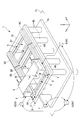
- FIG. 1 is a perspective view showing an overall configuration of a transport apparatus 1 according to the present embodiment.
- FIG. 2 is a perspective view showing a state of a part of the configuration of the transport apparatus 1 when viewed from a different viewpoint from that in FIG.
- the transport device 1 is a device that transports a flexible substrate S that is formed in a belt shape, and is provided, for example, on a floor surface FL of a manufacturing factory.
- the conveyance device 1 includes a base (pedestal) 2, a first rail 3, a second rail 4, a substrate feed mechanism 5, a substrate take-up mechanism 6, a rail drive mechanism 7, a roller drive unit 8, and a control device CONT. Yes.
- the transport apparatus 1 is used in a roll-to-roll system (hereinafter simply referred to as “roll system”) system in which various treatments are performed on the surface of a flexible substrate S formed in a strip shape.
- roll system a roll-to-roll system
- a display element electronic device
- a plane parallel to the floor surface FL in the XYZ orthogonal coordinate system is an XY plane.
- the direction (long direction) in which the substrate S moves by the roll method is defined as the Y direction
- the direction orthogonal to the Y direction is defined as the X direction.
- a direction perpendicular to the floor surface FL (XY plane) is taken as a Z-axis direction.
- the substrate S to be processed in the substrate processing apparatus PA for example, a foil such as a resin film or stainless steel can be used.
- the resin film is polyethylene resin, polypropylene resin, polyester resin, ethylene vinyl copolymer resin, polyvinyl chloride resin, cellulose resin, polyamide resin, polyimide resin, polycarbonate resin, polystyrene resin, vinyl acetate resin, polyethylene terephthalate, polyethylene Materials such as naphthalate and stainless steel foil can be used.
- the dimension in the short direction of the substrate S is, for example, about 50 cm to 2 m, and the dimension in the long direction (size for one roll) is, for example, 10 m or more.
- this dimension is only an example and is not limited thereto.
- the dimension in the short direction of the substrate S may be 1 m or less, 50 cm or less, or 2 m or more.
- a substrate S having a dimension in the short direction exceeding 2 m may be used.
- substrate S may be 10 m or less.
- the substrate S has a thickness of 1 mm or less, for example, and is formed to have flexibility.
- the term “flexibility” refers to the property that the substrate can be bent without being broken or broken even when a predetermined force of at least its own weight is applied to the substrate. Further, for example, the property of bending by the predetermined force is also included in the flexibility.
- the flexibility varies depending on the material, size, thickness, or environment such as temperature and humidity of the substrate.
- a single strip-shaped substrate may be used, but a configuration in which a plurality of unit substrates are connected and formed in a strip shape may be used.
- the substrate S preferably has a relatively small coefficient of thermal expansion so that the dimensions do not substantially change even when subjected to heat at a relatively high temperature (for example, about 200 ° C.) (thermal deformation is small).
- a relatively high temperature for example, about 200 ° C.
- an inorganic filler can be mixed with a resin film to reduce the thermal expansion coefficient.
- the inorganic filler include titanium oxide, zinc oxide, alumina, silicon oxide and the like.
- the base 2 has a base 2a, legs 2b, and a support 2c.
- Base portion 2a is placed on floor surface FL.
- a plurality of leg portions 2b are provided on the base portion 2a and support the support base 2c.
- the support base 2c is formed in, for example, a rectangle, and is provided with an opening to which the processing apparatus PA is attached and three openings 2d provided so as to sandwich the opening in the X direction. That is, the support 2c is provided with three openings 2d along the X direction.
- Guide rails 7r extending in parallel with the Y-axis direction are provided in the three openings 2d. Two guide rails 7r are provided in parallel in the X direction for each opening 2d.
- the first rail 3 is disposed along the + Y side of the support base 2c.
- the first rail 3 is divided into three unit rails 3A to 3C.
- Each of the unit rails 3A to 3C is disposed at a position corresponding to each of the three openings 2d of the support base 2c.
- the dimension in the X direction of the unit rails 3A to 3C is a value corresponding to the dimension in the X direction of each opening 2d.
- the second rail 4 is disposed along the ⁇ Y side side of the support base 2c.
- the second rail 4 is divided into three unit rails 4A to 4C.
- Each of the unit rails 4A to 4C is arranged at a position corresponding to each of the three openings 2d of the support base 2c, like the unit rails 3A to 3C.
- the X-direction dimensions of the unit rails 4A to 4C are values corresponding to the X-direction dimensions of the openings 2d, and are the same as the X-direction dimensions of the unit rails 3A to 3C. .
- the unit rails 3A to 3C of the first rail 3 and the unit rails 4A to 4C of the second rail 4 are respectively supported by guide rails 7r provided in the respective openings 2d and extending in the Y direction.
- the unit rails 3A to 3C are supported on the + Y side end of the guide rail 7r, and the unit rails 4A to 4C are supported on the ⁇ Y side end of the guide rail 7r.
- the unit rails 3A to 3C of the first rail 3 and the unit rails 4A to 4C of the second rail 4 are respectively arranged parallel to the X-axis direction. Further, since the guide rail 7r extends in parallel to the Y-axis direction, the unit rails 3A to 3C and the unit rails 4A to 4C can move in the Y direction on the guide rail 7r while maintaining a parallel state to each other. Is provided. As described above, the first rail 3 and the second rail 4 are configured to be linearly movable on a plane parallel to the XY plane by the guide rail 7r.
- the substrate delivery mechanism 5 is disposed on the first rail 3.
- the substrate delivery mechanism 5 has a roller support portion 5a and a supply roller 5b.
- the roller support portion 5a is connected to the first rail 3, and is provided so as to be movable (guided) along the first rail 3 in the X direction.
- the roller support portion 5a is movable over the unit rails 3A to 3C constituting the first rail 3.
- the supply roller 5b is rotatably supported by the roller support portion 5a.
- the supply roller 5b is supported so that the direction of the rotation axis coincides with a direction parallel to the X direction.
- the substrate S is wound around the supply roller 5b in a roll shape. As the supply roller 5b rotates, the substrate S wound around the supply roller 5b is sent out in the -Y direction.
- the supply roller 5a can be rotated by a motor or the like.
- the substrate winding mechanism 6 is disposed on the second rail 4.
- the substrate winding mechanism 6 includes a roller support portion 6a and a recovery roller 6b.
- the roller support portion 6 a is connected on the second rail 4 and is provided so as to be movable (guided) along the second rail 4 in the X direction.
- the roller support portion 6a is movable over the unit rails 4A to 4C constituting the second rail 4.
- the collection roller 6b is rotatably supported by the roller support portion 6a.
- the collection roller 6b is supported so that the direction of the rotation axis coincides with a direction parallel to the X direction.
- the substrate S is wound around the collection roller 6b in a roll shape. When the collection roller 6b rotates, the substrate S is wound around the collection roller 6b.
- the collection roller 6b can be rotated by a motor or the like.
- the rail drive mechanism 7 moves the first rail 3 and the second rail 4 in the Y direction along the guide rail 7r.
- the rail drive mechanism 7 can drive the first rail 3 for each of the unit rails 3A to 3C, and can drive the second rail 4 for each of the unit rails 4A to 4C.
- the control device CONT can control the drive amount, drive speed, drive timing, and the like by the rail drive mechanism 7.
- the rail drive mechanism 7 can move the unit rail 3A and the unit rail 4A closer to each other or away from each other along the guide rail 7r.
- the rail drive mechanism 7 can move the unit rail 3B and the unit rail 4B closer to each other or away from each other along the guide rail 7r.
- the rail drive mechanism 7 can move the unit rail 3C and the unit rail 4C closer to each other or away from each other along the guide rail 7r.
- the roller drive unit 8 has a first drive unit 83 and a second drive unit 84.
- the first drive unit 83 moves the roller support unit 5a in the X direction along the first rail 3, and rotates the supply roller 5b.
- the second drive unit 84 moves the roller support 6a along the second rail 4 in the X direction and rotates the collection roller 6b.
- the control device CONT can control the first drive unit 83 and the second drive unit 84 individually or in synchronization. Further, the control device CONT can control the drive amount, drive speed, drive timing, and the like in the first drive unit 83 and the second drive unit 84.
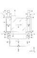
- FIG. 3 is a plan view showing the operation of the transfer device 1. First, the case where the operation
- control device CONT arranges the substrate feed mechanism 5 on the unit rail 3A of the first rail 3, and arranges the substrate take-up mechanism 6 on the unit rail 4A of the second rail 4.
- the supply roller 5b and the collection roller 6b are arranged in parallel so as to face each other in the Y direction.
- the substrate S wound in a roll shape is attached to the supply roller 5b.
- the reader Lf is attached to the tip Sf of the substrate S.
- the reader Lf may be omitted.
- the control device CONT moves the unit rail 4A of the second rail 4 in the + Y direction. By this operation, the supply roller 5b and the collection roller 6b come closer.
- the control device CONT rotates the supply roller 5b by the first drive unit 83 when the distance between the supply roller 5b and the collection roller 6b becomes the first distance D1.
- the tip Sf of the substrate S is sent out to the collection roller 6b side, and the tip Sf of the substrate S reaches the collection roller 6b and is wound around the collection roller 6b.
- the operation of winding the tip Sf of the substrate S around the collection roller 6b may be automated, but the tip Sf may be manually attached to the collection roller 6b by using a fixing tape or the like.
- the control device CONT rotates the supply roller 5b after the tip Sf of the substrate S is hung on the collection roller 6b, and the distance between the supply roller 5b and the collection roller 6b is the second distance (the substrate winding mechanism 6 is the original).
- the unit rail 4A is moved in the -Y direction until the distance reaches the position (1). By this operation, the tip Sf of the substrate S is pulled out in the ⁇ Y direction in a state where it is hung on the collection roller 6b.
- the control device CONT stops the movement of the substrate winding mechanism 6. Thereafter, as shown in FIG. 4, the control device CONT synchronizes the substrate feed mechanism 5 and the substrate take-up mechanism 6 with the first drive unit 83 and the second drive unit 84, respectively, on the unit rail 3B and the unit rail 4B. Move up. Prior to this operation, the processing device PA is disposed between the unit rail 3B and the unit rail 4B. At this time, the substrate delivery mechanism 5 and the substrate take-up mechanism 6 are controlled so that the substrate S stretched between the supply roller 5b and the collection roller 6b is stretched flatly by being given an appropriate tension in the Y direction. To do.
- the processing apparatus PA has various processing units for forming, for example, organic EL elements on the surface Sa to be processed of the substrate S.
- a processing unit for example, a partition forming device for forming a partition on the surface Sa, an electrode forming device for forming an electrode for driving an organic EL element, and a light emitting layer A light emitting layer forming apparatus or the like is provided.
- a droplet coating apparatus for example, an ink jet type coating apparatus, a spray coating type coating apparatus, a gravure printing machine, etc.
- a deposition apparatus such as a vapor deposition apparatus or a sputtering apparatus, an exposure apparatus, a developing apparatus, or a surface modification. Examples thereof include a device and a cleaning device.
- the processing apparatus PA is not limited to the processing section for forming the organic EL element, and it is needless to say that a processing apparatus having a processing section for forming other elements may be arranged.
- the controller CONT arranges the substrate delivery mechanism 5 and the substrate take-up mechanism 6 on the unit rails 3B and 4B, respectively, and then rotates the supply roller 5b and the recovery roller 6b in accordance with the processing timing of the processing apparatus PA.
- the substrate S is sent out from the supply roller 5b as shown by the arrow K2, and the substrate S is wound up by the recovery roller 6b.
- the processing by the processing apparatus PA is performed on the processing surface Sa of the substrate S. It will be done against.
- the control device CONT adjusts the moving speed of the substrate S moving from the supply roller 5b to the collection roller 6b according to the processing speed of the processing device PA. For example, depending on the winding diameter R1 of the substrate S wound around the supply roller 5b and the winding diameter R2 of the substrate S wound around the recovery roller 6b, the driving speeds in the first drive unit 83 and the second drive unit 84 To adjust. By this operation, the substrate S is transported while the transport speed is constant.
- the control device CONT may adjust the distance between the supply roller 5b and the collection roller 6b according to the processing position of the processing device PA, the dimension in the Y direction, and the like.
- the control unit CONT moves the unit rail 3B or the unit rail 4B, for example, in the Y direction by the rail drive mechanism 7.
- Part or all of the constituent elements of the display element are sequentially formed on the substrate S by the processing apparatus PA.
- the control device CONT synchronizes the substrate delivery mechanism 5 and the substrate take-up mechanism 6 with the first drive unit 83 and the second drive unit 84, respectively on the unit rail 3C and the unit rail. Move it up 4C.
- the control device CONT synchronizes the substrate delivery mechanism 5 and the substrate take-up mechanism 6 with the first drive unit 83 and the second drive unit 84, respectively on the unit rail 3C and the unit rail. Move it up 4C.
- the control device CONT synchronizes the substrate delivery mechanism 5 and the substrate take-up mechanism 6 with the first drive unit 83 and the second drive unit 84, respectively on the unit rail 3C and the unit rail. Move it up 4C.
- the control device CONT synchronizes the substrate delivery mechanism 5 and the substrate take-up mechanism 6 with the first drive unit 83 and the second drive unit 84, respectively on the unit rail 3C and the unit rail. Move it up 4C.
- the control device CONT synchronizes the substrate delivery mechanism 5 and the substrate take-up mechanism 6 with the first drive
- the control device CONT stops the movement of the substrate feed mechanism 5 and the substrate take-up mechanism 6, and then moves the unit rail 4C in the + Y direction while rotating the collection roller 6b. By this operation, the supply roller 5b and the recovery roller 6b come close again while the recovery roller 6b winds up the substrate S.
- the control device CONT rotates the supply roller 5b by the first drive unit 83 as shown in FIG. 5 after the distance between the supply roller 5b and the collection roller 6b reaches the third distance D2.
- the third distance D2 can be set equal to the first distance D1, for example.
- the distance between the supply roller 5b and the recovery roller 6b is the second distance (the distance at which the substrate winding mechanism 6 reaches the original position).
- the unit rail 4C is moved in the -Y direction.
- the roll-shaped substrate S wound around the collection roller 6b is moved to the next processing apparatus. Or when all the processes are performed with respect to the board
- the base 2 is provided with the first rail 3 and the second rail 4, and the first rail 3 is provided with the supply roller 5 b movable on the first rail 3.
- the second rail 4 is provided with a collection roller 6b movable on the second rail 4, and the first rail 3 and the second rail 4 can be driven by the rail drive mechanism 7,
- the substrate S can be transported in a compact manner between the supply roller 5b and the collection roller 6b.
- the technical scope of the present invention is not limited to the above-described embodiment, and appropriate modifications can be made without departing from the spirit of the present invention.
- the structure which the 1st rail 3 and the 2nd rail 4 move to a direction parallel to XY plane was mentioned as an example, it was not restricted to this.
- the first rail 3 and the second rail 4 may be configured to be movable in the Z direction.
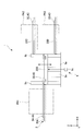
- FIG. 6 is a plan view showing another example of the transfer apparatus 1
- FIG. 7 is a side view showing an example of the transfer apparatus 1 of FIG.
- the configuration corresponding to the base 2 of the transport apparatus 1 is configured to have four support bases 20A to 20D in this example.
- Unit rails 3A and 4A are disposed on the support 20A.
- the first processing device PA1 is connected between the unit rail 3A and the unit rail 4A.
- the unit rail 3B and the unit rail 4B are arranged on the support base 20B.
- the support table 20B is separated from the support table 20A, the support table 20C, and the support table 20D.
- the support 20B is provided so as to be movable independently in the Z direction by the elevating mechanism 9.
- the elevating mechanism 9 has a support column 9a, a guide column 9b, and an actuator 9c. With the drive of the actuator 9c, the support base 20B is moved in the Z direction along the guide column 9b while being supported by the support column 9a.
- the drive amount, drive speed, and drive timing of the actuator 9c can be controlled by, for example, the second controller CONT2. In addition, you may make it carry out collectively in the control apparatus CONT.
- the support table 20C and the support table 20D are arranged side by side in the Z direction.
- the support table 20C is provided on the + Z side, and the support table 20D is provided on the -Z side.
- Unit rails 3C and 4C are provided on the support base 20C.
- a second processing device PA2 can be connected between the unit rail 3C and the unit rail 4C. In the second processing apparatus PA2, for example, a post-process process of the first processing apparatus PA1 is performed.
- Unit rails 3D and 4D are provided on the support base 20D.
- a third processing apparatus PA3 can be connected between the unit rail 3D and the unit rail 4D.
- the same processing as the second processing device PA2 here, the post-processing of the first processing device PA1 is performed.
- the second processing apparatus PA2 and the third processing apparatus PA3 will be described as an example in which the same processing (post-process processing of the first processing apparatus PA1) is performed. It is not limited to this.
- the second processing device PA2 and the third processing device PA3 may be configured to perform different processes.
- the second processing device PA2 and the third processing device PA3 are identically configured, and the processing conditions (temperature, humidity, processing time, substrate feed rate, tension amount, etc.) are set differently depending on the device. It does not matter if such a configuration is used.
- the support table 20B is provided so as to be movable to the same Z position as the support table 20C and the support table 20D by the elevating mechanism 9.
- the unit rails 3B and 4B can be connected to the unit rails 3C and 4C.
- the control device CONT adjusts the distance between the unit rail 3B and the unit rail 4B to be equal to the distance between the unit rail 3C and the unit rail 4C.
- the control device CONT adjusts the distance between the unit rail 3B and the unit rail 4B to be equal to the distance between the unit rail 3D and the unit rail 4D.
- the substrate delivery mechanism 5 is disposed on the first rail 3 and the substrate take-up mechanism 6 is disposed on the second rail 4, as in the above embodiment.
- the substrate S is stretched between the supply roller 5b and the collection roller 6b, and the substrate S is transported between the two rollers.
- the support table 20B is configured to selectively access both the support table 20C and the support table 20D, the substrate S that has passed through the first processing apparatus PA1 becomes the second processing apparatus PA2 and the third processing apparatus PA3.
- the movement destination of the substrate S can be set so as to move alternately. Thereby, for example, when the transport speed of the substrate S in the second processing apparatus PA2 and the third processing apparatus PA3 is slower than the transport speed of the substrate S in the first processing apparatus PA1, the substrate S is in the second processing apparatus PA2 and It is possible to prevent the process from waiting before the third processing apparatus PA3.
- each of the substrate delivery mechanism 5 and the substrate take-up mechanism 6 is provided with an elevator that adjusts the heights of the supply roller 5b and the recovery roller 6b, whereby the substrate S across the substrate take-up mechanism 6 from the substrate delivery mechanism 5 is provided. Height or slope can be adjusted.
- a state in which the substrate S is stretched between the supply roller 5b and the collection roller 6b is referred to as a substrate set (roll set).
- the collection roller and the supply roller of the first substrate set are moved onto the support base 20B, and then a new processing target is set.
- the supply roller and the recovery roller of the second substrate set can be carried into the first processing apparatus PA1.
- the timing at which the first substrate set is carried into either the second processing apparatus PA2 or the third processing apparatus PA3 and the timing at which the second substrate set is carried into the first processing apparatus PA1 can be adjusted.
- Substrate sets can be processed sequentially. Further, by providing a configuration like the support 20B after the second processing apparatus PA2 and the third processing apparatus PA3, the substrate set can be carried into the apparatus (PA4) for the next processing step.
- the substrate S is moved between the processing apparatuses PA (PA1, PA2, PA3) in the X direction in a state where the substrate S is stretched between the feeding mechanism 5 and the winding mechanism 6. be able to.
- PA processing apparatus
- the upper unit 100A and the lower unit 100B can be separated from each other, and the substrate feeding mechanism 5 and the substrate are subjected to a tension in the Y direction.
- the substrate S spanned between the winding mechanism 6 can pass through the space between the upper unit 100A and the lower unit 100B in the X direction.
- Rollers 101a, 101b, 102a, 102b for guiding the substrate S are provided on the inlet side and the outlet side of the substrate S of the upper unit 100A and the lower unit 100B.
- a processing apparatus PA either one or both of the upper unit 100A and the lower unit 100B can be moved in the Z direction by a necessary amount by a lifting mechanism (not shown).
- a printing machine including an ink jet printer
- a plasma apparatus a vapor deposition apparatus, an exposure apparatus, and the like can be used.
Landscapes
- Container, Conveyance, Adherence, Positioning, Of Wafer (AREA)
- Electroluminescent Light Sources (AREA)
- Liquid Crystal (AREA)
- Advancing Webs (AREA)
- Registering, Tensioning, Guiding Webs, And Rollers Therefor (AREA)
Abstract
Description
本願は、2011年2月24日に出願された米国特許仮出願61/446,150号に基づき優先権を主張し、その内容をここに援用する。
図1は、本実施形態に係る搬送装置1の全体構成を示す斜視図である。図2は、搬送装置1の一部の構成について、図1とは異なる視点から見たときの状態を示す斜視図である。
図1及び図2に示すように、搬送装置1は、帯状に形成され可撓性を有する基板Sを搬送する装置であり、例えば製造工場の床面FLに設けられている。搬送装置1は、基台(ペデスタル)2、第一レール3、第二レール4、基板送り出し機構5、基板巻き取り機構6、レール駆動機構7、ローラー駆動部8及び制御装置CONTを有している。
まず、供給ローラー5bと回収ローラー6bとの間に基板Sを掛け渡す動作を行う場合について説明する。
上記実施形態では、第一レール3及び第二レール4がXY平面に平行な方向へ移動する構成を例に挙げて説明したが、これに限られることは無い。例えば、第一レール3及び第二レール4がZ方向に移動可能な構成としても構わない。
図6及び図7に示すように、搬送装置1の基台2に相当する構成は、本例では、4つの支持台20A~20Dを有する構成となっている。支持台20Aには、単位レール3A及び4Aが配置されている。単位レール3Aと単位レール4Aとの間に第一処理装置PA1が接続されるようになっている。
なお、図6及び図7で示す実施形態では、第二処理装置PA2及び第三処理装置PA3において、同一の処理(第一処理装置PA1の後工程処理)が行われる例に挙げて説明するが、これに限られることは無い。例えば、第二処理装置PA2及び第三処理装置PA3では、それぞれ別々の処理が行われる構成としても構わない。
さらに、第二処理装置PA2と第三処理装置PA3を、構成上は全く同一の装置とし、装置によって処理条件(温度や湿度、処理時間、基板の送り速度、テンション量等)を異ならせて設定するような構成としても構わない。
また、第2処理装置PA2、第3処理装置PA3の後にも、支持台20Bのような構成を設けることにより、次の処理工程の装置(PA4)に、基板セットを搬入できる。
Claims (16)
- 帯状に形成され可撓性を有する基板を送り出す供給ローラーと、
前記供給ローラーから送り出された前記基板を巻き取る回収ローラーと、
前記供給ローラーから前記回収ローラーへ向けた前記基板の送り方向に対して交差する方向に、前記供給ローラーと前記回収ローラーとを駆動する駆動部と
を備える搬送装置。 - 前記駆動部は、前記供給ローラーと前記回収ローラーとを同期駆動する
請求項1に記載の搬送装置。 - 基台と、
前記基台に設けられ、前記供給ローラーを前記交差方向に案内する第一レールと、
前記基台のうち前記第一レールに対して離れた位置に設けられ、前記回収ローラーを前記交差方向に案内する第二レールと
を備える請求項1又は請求項2に記載の搬送装置。 - 前記第一レールと前記第二レールとのうち少なくとも一方を駆動し、前記供給ローラーと前記回収ローラーとが互いに接近又は離間させるレール駆動部
を備える請求項3に記載の搬送装置。 - 前記レール駆動部は、前記第一レールと前記第二レールとを互いに接近又は離間可能に前記第一レール及び前記第二レールのうち少なくとも一方を案内する案内部を有する
請求項4に記載の搬送装置。 - 前記供給ローラーから前記回収ローラーに、前記基板の先端部を送り出す場合に、前記第一レールと前記第二レールとの間が第一距離となるように前記レール駆動部を制御する制御部を有する
請求項4又は請求項5に記載の搬送装置。 - 前記制御部は、前記基板の前記先端部が前記回収ローラーに巻き取られた後、前記第一レールと前記第二レールとの間が第二距離となるように前記レール駆動部を制御する
請求項6に記載の搬送装置。 - 前記制御部は、前記回収ローラーによって前記基板の後端部まで巻き取る場合に、前記第一レールと前記第二レールとの間が第三距離となるように前記レール駆動部を制御する
請求項6又は請求項7に記載の搬送装置。 - 前記制御部は、前記基板の前記後端部が前記回収ローラーに巻き取られた後、前記第一レールと前記第二レールとの間が第二距離となるように前記レール駆動部を制御する
請求項8に記載の搬送装置。 - 前記制御部は、前記レール駆動部を制御して、前記供給ローラーと前記回収ローラーとの間で前記基板が掛け渡されている状態において前記基板のうち掛け渡された部分の長さを調整する
請求項6から請求項9のうちいずれか一項に記載の搬送装置。 - 前記レール駆動部は、前記第一レール及び前記第二レールを重力方向に案内する第二案内部を有する
請求項4から請求項10のうちいずれか一項に記載の搬送装置。 - 前記レール駆動部による前記第二案内部を介した駆動を制御する第二制御部
を更に備え、
前記第二制御部は、前記供給ローラーから前記回収ローラーへと移動する前記基板の移動速度に応じて、重力方向上に設定された複数の位置の間を前記第一レール及び前記第二レールが移動するように、前記レール駆動部による駆動量を調整する
請求項11に記載の搬送装置。 - 前記第一レール及び前記第二レールは、複数の単位レールに分割されており、
前記レール駆動部は、前記単位レールごとに駆動可能である
請求項3から請求項12のうちいずれか一項に記載の搬送装置。 - 前記第一レールと前記第二レールは、前記供給ローラーから前記回収ローラー
へ向けて搬送される前記基板に所定の処理を施す処理装置を挟んで設置される
請求項3から請求項12のうちいずれか一項に記載の搬送装置。 - 前記処理装置は、前記基板上に異なる処理を施す為の複数の処理装置を含み、
該複数の処理装置が前記第一レールと前記第二レールの延設方向に並べて配置
される請求項14に記載の搬送装置。 - 請求項14に記載の搬送装置と前記複数の処理装置を床上に設置して、前記基板上に可撓性の表示デバイス、又は可撓性の電子回路を形成する製造システム。
Priority Applications (5)
| Application Number | Priority Date | Filing Date | Title |
|---|---|---|---|
| KR1020137008344A KR101608565B1 (ko) | 2011-02-24 | 2012-02-20 | 가요성 기판의 반송장치 및 표시 디바이스 또는 전자회로의 제조 시스템 |
| HK13108175.5A HK1181021B (en) | 2011-02-24 | 2012-02-20 | Device for transporting flexible substrate, and system for manufacturing display device or electrical circuit |
| KR1020167008032A KR101652674B1 (ko) | 2011-02-24 | 2012-02-20 | 시트 기판의 반송장치, 및 처리장치 |
| JP2013501025A JP5821944B2 (ja) | 2011-02-24 | 2012-02-20 | 搬送装置、製造システム |
| CN201280003198.8A CN103153830B (zh) | 2011-02-24 | 2012-02-20 | 可挠性基板的搬送装置及显示元件或电子电路的制造系统 |
Applications Claiming Priority (2)
| Application Number | Priority Date | Filing Date | Title |
|---|---|---|---|
| US201161446150P | 2011-02-24 | 2011-02-24 | |
| US61/446,150 | 2011-02-24 |
Publications (1)
| Publication Number | Publication Date |
|---|---|
| WO2012115037A1 true WO2012115037A1 (ja) | 2012-08-30 |
Family
ID=46720814
Family Applications (1)
| Application Number | Title | Priority Date | Filing Date |
|---|---|---|---|
| PCT/JP2012/053961 Ceased WO2012115037A1 (ja) | 2011-02-24 | 2012-02-20 | 可撓性基板の搬送装置及び表示デバイス又は電子回路の製造システム |
Country Status (5)
| Country | Link |
|---|---|
| JP (2) | JP5821944B2 (ja) |
| KR (2) | KR101652674B1 (ja) |
| CN (2) | CN103153830B (ja) |
| TW (4) | TWI606970B (ja) |
| WO (1) | WO2012115037A1 (ja) |
Families Citing this family (2)
| Publication number | Priority date | Publication date | Assignee | Title |
|---|---|---|---|---|
| CN106449491A (zh) * | 2016-12-12 | 2017-02-22 | 武汉华星光电技术有限公司 | 柔性显示器件处理系统及方法 |
| CN107032159B (zh) * | 2017-04-20 | 2019-04-09 | 京东方科技集团股份有限公司 | 膜材转移装置及膜材转移控制方法 |
Citations (1)
| Publication number | Priority date | Publication date | Assignee | Title |
|---|---|---|---|---|
| JP2002035982A (ja) * | 2000-07-27 | 2002-02-05 | Uht Corp | レーザー加工装置 |
Family Cites Families (17)
| Publication number | Priority date | Publication date | Assignee | Title |
|---|---|---|---|---|
| US4485982A (en) * | 1982-11-24 | 1984-12-04 | Xerox Corporation | Web tracking system |
| DE3426976A1 (de) * | 1984-07-21 | 1986-01-30 | Graphischer Maschinenbau GmbH, 1000 Berlin | Vorrichtung zur durchfuehrung eines rollenwechsels |
| JP2688328B2 (ja) * | 1994-08-29 | 1997-12-10 | 株式会社神戸製鋼所 | 帯状物移送方向転換装置 |
| JP3233542B2 (ja) * | 1995-02-14 | 2001-11-26 | 株式会社オーシーシー | 金属管被覆光ファイバケーブルの製造方法及び製造装置 |
| US5744778A (en) * | 1996-04-02 | 1998-04-28 | G&H Diversified Manufacturing, Inc. | Tube handling method and apparatus for cutting machine |
| JP2000143052A (ja) * | 1998-11-05 | 2000-05-23 | Sony Corp | フィルム状の被加工物の供給装置及び供給方法 |
| JP2000303178A (ja) * | 1999-04-16 | 2000-10-31 | Sanyo Electric Co Ltd | 薄膜形成装置 |
| SE524962C2 (sv) * | 2002-05-30 | 2004-11-02 | Drymilko Ag | Förfarande för tillverkning av etiketter och anordning härför |
| US20040150135A1 (en) * | 2002-06-26 | 2004-08-05 | Michael Hennessey | Method of melt-forming optical disk substrates |
| ATE357398T1 (de) * | 2003-07-28 | 2007-04-15 | Hauni Maschinenbau Ag | Transporteinrichtung und verfahren zum transportieren eines hüllmaterialstreifens |
| DE102004024461A1 (de) * | 2004-05-14 | 2005-12-01 | Konarka Technologies, Inc., Lowell | Vorrichtung und Verfahren zur Herstellung eines elektronischen Bauelements mit zumindest einer aktiven organischen Schicht |
| JP2005349632A (ja) | 2004-06-09 | 2005-12-22 | Canon Inc | インクジェット記録装置 |
| JP2006100868A (ja) | 2004-09-28 | 2006-04-13 | Hitachi Kokusai Electric Inc | 無線通信システム |
| GB2439001B (en) | 2005-03-18 | 2011-03-09 | Konica Minolta Holdings Inc | Method of forming organic compound layer, method of manufacturing organic el element and organic el element |
| JP4870502B2 (ja) * | 2006-09-15 | 2012-02-08 | 株式会社ヒラノテクシード | 有機elシート製造装置 |
| JP4914815B2 (ja) * | 2007-11-28 | 2012-04-11 | ユニ・チャーム株式会社 | 加工装置 |
| JP2010097803A (ja) * | 2008-10-16 | 2010-04-30 | Konica Minolta Holdings Inc | 有機エレクトロニクス素子の作製方法、有機エレクトロニクス素子および有機エレクトロルミネッセンス素子 |
-
2012
- 2012-02-20 KR KR1020167008032A patent/KR101652674B1/ko active Active
- 2012-02-20 WO PCT/JP2012/053961 patent/WO2012115037A1/ja not_active Ceased
- 2012-02-20 CN CN201280003198.8A patent/CN103153830B/zh active Active
- 2012-02-20 CN CN201610169564.7A patent/CN105836510B/zh active Active
- 2012-02-20 JP JP2013501025A patent/JP5821944B2/ja active Active
- 2012-02-20 KR KR1020137008344A patent/KR101608565B1/ko active Active
- 2012-02-22 TW TW105131469A patent/TWI606970B/zh active
- 2012-02-22 TW TW107110611A patent/TWI701206B/zh active
- 2012-02-22 TW TW101105766A patent/TWI560127B/zh active
- 2012-02-22 TW TW106136141A patent/TWI623480B/zh active
-
2015
- 2015-08-06 JP JP2015156012A patent/JP6065954B2/ja active Active
Patent Citations (1)
| Publication number | Priority date | Publication date | Assignee | Title |
|---|---|---|---|---|
| JP2002035982A (ja) * | 2000-07-27 | 2002-02-05 | Uht Corp | レーザー加工装置 |
Also Published As
| Publication number | Publication date |
|---|---|
| KR20160040317A (ko) | 2016-04-12 |
| CN103153830A (zh) | 2013-06-12 |
| KR101652674B1 (ko) | 2016-08-30 |
| CN103153830B (zh) | 2016-04-20 |
| KR101608565B1 (ko) | 2016-04-01 |
| KR20130143024A (ko) | 2013-12-30 |
| TW201827321A (zh) | 2018-08-01 |
| JP6065954B2 (ja) | 2017-01-25 |
| HK1181021A1 (zh) | 2013-11-01 |
| TW201803792A (zh) | 2018-02-01 |
| TWI606970B (zh) | 2017-12-01 |
| TWI623480B (zh) | 2018-05-11 |
| TW201702161A (zh) | 2017-01-16 |
| TW201242878A (en) | 2012-11-01 |
| TWI560127B (en) | 2016-12-01 |
| TWI701206B (zh) | 2020-08-11 |
| JP5821944B2 (ja) | 2015-11-24 |
| JPWO2012115037A1 (ja) | 2014-07-07 |
| HK1221701A1 (zh) | 2017-06-09 |
| CN105836510A (zh) | 2016-08-10 |
| CN105836510B (zh) | 2017-11-28 |
| JP2016026370A (ja) | 2016-02-12 |
Similar Documents
| Publication | Publication Date | Title |
|---|---|---|
| CN104203779B (zh) | 搬运装置、及电子器件的形成方法 | |
| KR101723354B1 (ko) | 기판처리방법 및 기판처리장치 | |
| JP2009117571A (ja) | 基板処理装置及び塗布装置及び塗布方法 | |
| JP5765240B2 (ja) | 帯状のシート基板のための搬送装置及び処理装置、デバイス製造方法 | |
| KR102126421B1 (ko) | 롤용 카세트 장치 | |
| JP6065954B2 (ja) | 製造システム | |
| HK1181021B (en) | Device for transporting flexible substrate, and system for manufacturing display device or electrical circuit | |
| HK1221701B (en) | Device for transporting and processing sheet substrate | |
| JP5861319B2 (ja) | 搬送装置及び基板処理装置 | |
| JP2013180863A (ja) | 搬送装置 | |
| JP5240505B2 (ja) | シート状体搬送装置及びシート状体搬送方法 | |
| JP2013189307A (ja) | 搬送装置及び基板処理装置 | |
| JP2015009951A (ja) | 基板把持装置 | |
| KR20150071854A (ko) | 플렉서블 기판 증착장치 | |
| HK1224264B (en) | Substrate processing device | |
| JP2010264396A (ja) | 塗布装置 |
Legal Events
| Date | Code | Title | Description |
|---|---|---|---|
| WWE | Wipo information: entry into national phase |
Ref document number: 201280003198.8 Country of ref document: CN |
|
| 121 | Ep: the epo has been informed by wipo that ep was designated in this application |
Ref document number: 12750107 Country of ref document: EP Kind code of ref document: A1 |
|
| ENP | Entry into the national phase |
Ref document number: 2013501025 Country of ref document: JP Kind code of ref document: A Ref document number: 20137008344 Country of ref document: KR Kind code of ref document: A |
|
| NENP | Non-entry into the national phase |
Ref country code: DE |
|
| 122 | Ep: pct application non-entry in european phase |
Ref document number: 12750107 Country of ref document: EP Kind code of ref document: A1 |