WO2012114910A1 - 歯形部品の製造方法、歯形部品の製造装置、歯形部品 - Google Patents
歯形部品の製造方法、歯形部品の製造装置、歯形部品 Download PDFInfo
- Publication number
- WO2012114910A1 WO2012114910A1 PCT/JP2012/053133 JP2012053133W WO2012114910A1 WO 2012114910 A1 WO2012114910 A1 WO 2012114910A1 JP 2012053133 W JP2012053133 W JP 2012053133W WO 2012114910 A1 WO2012114910 A1 WO 2012114910A1
- Authority
- WO
- WIPO (PCT)
- Prior art keywords
- axial direction
- tooth profile
- mold
- protrusion
- tooth
- Prior art date
- Legal status (The legal status is an assumption and is not a legal conclusion. Google has not performed a legal analysis and makes no representation as to the accuracy of the status listed.)
- Ceased
Links
Images





Classifications
-
- B—PERFORMING OPERATIONS; TRANSPORTING
- B21—MECHANICAL METAL-WORKING WITHOUT ESSENTIALLY REMOVING MATERIAL; PUNCHING METAL
- B21K—MAKING FORGED OR PRESSED METAL PRODUCTS, e.g. HORSE-SHOES, RIVETS, BOLTS OR WHEELS
- B21K1/00—Making machine elements
- B21K1/28—Making machine elements wheels; discs
- B21K1/30—Making machine elements wheels; discs with gear-teeth
-
- F—MECHANICAL ENGINEERING; LIGHTING; HEATING; WEAPONS; BLASTING
- F16—ENGINEERING ELEMENTS AND UNITS; GENERAL MEASURES FOR PRODUCING AND MAINTAINING EFFECTIVE FUNCTIONING OF MACHINES OR INSTALLATIONS; THERMAL INSULATION IN GENERAL
- F16H—GEARING
- F16H55/00—Elements with teeth or friction surfaces for conveying motion; Worms, pulleys or sheaves for gearing mechanisms
- F16H55/02—Toothed members; Worms
- F16H55/17—Toothed wheels
-
- Y—GENERAL TAGGING OF NEW TECHNOLOGICAL DEVELOPMENTS; GENERAL TAGGING OF CROSS-SECTIONAL TECHNOLOGIES SPANNING OVER SEVERAL SECTIONS OF THE IPC; TECHNICAL SUBJECTS COVERED BY FORMER USPC CROSS-REFERENCE ART COLLECTIONS [XRACs] AND DIGESTS
- Y10—TECHNICAL SUBJECTS COVERED BY FORMER USPC
- Y10T—TECHNICAL SUBJECTS COVERED BY FORMER US CLASSIFICATION
- Y10T29/00—Metal working
- Y10T29/49—Method of mechanical manufacture
- Y10T29/49462—Gear making
- Y10T29/49467—Gear shaping
- Y10T29/49474—Die-press shaping
-
- Y—GENERAL TAGGING OF NEW TECHNOLOGICAL DEVELOPMENTS; GENERAL TAGGING OF CROSS-SECTIONAL TECHNOLOGIES SPANNING OVER SEVERAL SECTIONS OF THE IPC; TECHNICAL SUBJECTS COVERED BY FORMER USPC CROSS-REFERENCE ART COLLECTIONS [XRACs] AND DIGESTS
- Y10—TECHNICAL SUBJECTS COVERED BY FORMER USPC
- Y10T—TECHNICAL SUBJECTS COVERED BY FORMER US CLASSIFICATION
- Y10T74/00—Machine element or mechanism
- Y10T74/19—Gearing
- Y10T74/1987—Rotary bodies
Definitions
- the present invention relates to a tooth profile component manufacturing method, a tooth profile component manufacturing apparatus, and a tooth profile component for manufacturing a tooth profile component having a tooth profile such as a bevel gear by forging.
- a tooth profile part having a tooth profile part is manufactured by forging a material.
- the material is compressed from the axial direction of the columnar material and the material constituting the material flows toward the outside in the radial direction of the material, and the material constituting the material is filled inside the mold.
- a tooth profile component having a tooth profile portion on the outer peripheral surface is manufactured.
- the constituent material of the material is filled in the inner part of the material in the radial direction in the mold, but thereafter, the constituent material of the material is directed toward the outer side of the material in the radial direction. Flow in one direction. Further, if the material is further compressed from the axial direction of the material, the surface pressure of the part that is already filled with the constituent material of the material in the molding die is increased, so it is necessary to further increase the load (molding load) applied to the material. . For this reason, the load on the mold becomes large, and the life of the mold is shortened.
- Patent Document 1 discloses a forging technique.
- the ring-shaped material is pressurized from the axial direction by a pressurizing mechanism while restraining the outer peripheral surface of the ring-shaped material, and the constituent materials of the ring-shaped material are made to flow in the pressurizing direction.
- the tooth profile of the mold is filled.
- a part of the constituent material of the ring-shaped material is pushed out as a surplus into an open space communicating with the tooth profile portion of the mold.
- the constituent material of the ring-shaped material can be flowed under a certain pressure, and the variation in the product size and accuracy due to the variation in the material volume can be reduced.
- the present invention has been made to solve the above-described problems, and provides a tooth profile component manufacturing method, a tooth profile component manufacturing apparatus, and a tooth profile component capable of improving the life of a mold. Is an issue.
- One aspect of the present invention made to solve the above problems is a method of manufacturing a tooth profile component using a mold based on a rotationally symmetric material.
- a first projecting portion provided annularly in the circumferential direction so as to protrude in the axial direction on one end surface in the axial direction, and the molding die is recessed in the axial direction.
- a first indentation provided annularly in the circumferential direction; and provided in an annular shape in the circumferential direction so as to be recessed in the axial direction on the opposite side of the axial direction across the material with respect to the first indentation
- the R-shaped portion of the material is brought into contact with the tooth forming shape portion of the mold, and the first protrusion portion of the material is inserted into the first recess portion.
- a load is applied toward the axial direction with respect to the radial center portion of the material.
- the material of the material of the first protrusion is changed to the first depression.
- the load is maximized to flow to form a second protrusion, between the tooth profile and the tooth forming profile, between the first protrusion and the mold, and the first A space is provided between the two protrusions and the mold.
- the space is provided between the mold and the material, and the constituent material of the material is placed in the mold. Not charging. Thereby, there is room for the constituent material of the material to flow in this space. Therefore, it is possible to prevent the forming load from becoming extremely large as in closed forging. Therefore, since the load on the mold can be suppressed, the life of the mold can be improved.
- the constituent material of the raw material is caused to flow in three directions, a direction toward the outer side in the radial direction, a direction toward the first depression of the mold, and a direction toward the second depression of the mold, The effect of reducing the molding load is increased. Therefore, since the load on the mold can be suppressed, the life of the mold can be improved.
- the outer shape of the second recess is smaller in the axial direction.
- the constituent material of the material is difficult to flow in the second recess portion of the tooth forming mold, the material does not fill the recess portion of the mold when the tooth profile portion is formed, and the material and the mold A space is easily provided between the two. Therefore, the molding load can be prevented from becoming extremely large regardless of the fluidity of the constituent materials of the material. Therefore, since the load on the mold can be suppressed regardless of the fluidity of the constituent materials of the material, the life of the mold can be improved.
- the first dent and the second dent are formed at symmetrical positions in the axial direction.
- the tooth profile part is preferably a differential side gear of a differential.
- the differential side gear can be mass-produced while reducing the manufacturing cost.
- Another aspect of the present invention which has been made to solve the above problems, is a tooth profile component manufacturing apparatus manufactured using a mold on the basis of a rotationally symmetric material, wherein the material is disposed on a radially outer portion.
- An R-shaped portion, and a first protrusion provided annularly in the circumferential direction so as to protrude in the axial direction on one end surface in the axial direction, and the molding die is recessed in the axial direction
- a first indentation provided annularly in the circumferential direction, and annulus in the circumferential direction so as to be depressed in the axial direction on the opposite side of the axial direction across the material relative to the first indentation
- a second recess portion provided, the R-shaped portion of the material is brought into contact with the tooth forming shape portion of the mold, and the first protrusion portion of the material is inserted into the first recess portion.
- the load is directed toward the axial direction with respect to the radial center portion of the material.
- forming the tooth profile portion in the outer portion of the raw material by causing the constituent material of the raw material to flow outward in the radial direction, so that the constituent material of the raw material of the first protrusion is the first
- the material of the material of the intermediate portion between the central portion and the outer portion is made to flow toward the inside of the second hollow portion.
- the space is provided between the mold and the material, and the constituent material of the material is placed in the mold. Not charging. Thereby, there is room for the constituent material of the material to flow in this space. Therefore, it is possible to prevent the forming load from becoming extremely large as in closed forging. Therefore, since the load on the mold can be suppressed, the life of the mold can be improved.
- a tooth profile part manufactured using a mold based on a rotationally symmetric material, wherein the material has an R shape in a radially outer portion.
- a first projecting portion provided annularly in the circumferential direction so as to protrude in the axial direction on one end surface in the axial direction, and the molding die is recessed in the axial direction.
- a first indentation provided annularly in the direction, and provided in an annular shape in the circumferential direction so as to be indented in the axial direction on the opposite side of the axial direction across the material relative to the first indentation.
- a second depression, and the R-shaped portion of the material is brought into contact with the tooth forming portion of the mold, and the first protrusion of the material is inserted into the first depression. And apply a load in the axial direction to the central portion of the material in the radial direction.
- the material of the material of the first protrusion is changed to the first recess. And flow in the axial direction toward the inside of the second recess, and the material of the material in the intermediate portion between the central portion and the outer portion flows in the axial direction.
- the second projection is formed, and between the tooth profile and the tooth formation profile, between the first projection and the mold, and the second
- the first projection is provided on one end surface in the axial direction, and the other end surface in the axial direction is provided with a space between the projection portion and the molding die.
- a second protrusion is provided, and the second protrusion is opposed to the tooth profile. That is provided inside of the radial Te, characterized by.
- the space is provided between the mold and the material, and the constituent material of the material is placed in the mold. Not charging. Thereby, there is room for the constituent material of the material to flow in this space. Therefore, it is possible to prevent the forming load from becoming extremely large as in closed forging. Therefore, since the load on the mold can be suppressed, the life of the mold can be improved.
- the second protrusion is provided on the inner side in the radial direction with respect to the tooth profile (the inner side of the inner diameter end face of the tooth profile), when the tooth profile meshes with another tooth profile component, the functionality of the tooth profile component is improved. Does not affect.
- the life of the mold can be improved.
- a differential side gear used for a differential in a vehicle will be described as an example.
- the differential side gear of the differential device is a gear that is rotatably supported by the drive shaft in a state of meshing with the differential pinion gear in the differential case.
- the manufacturing apparatus 1 manufactures the differential side gear 12 (refer FIG. 11) provided with the bevel gear part 11 from the raw material 10 (refer FIG. 3) of a rotationally symmetric shape by forging.
- the manufacturing apparatus 1 has outer molds 14, tooth-forming molds 16, and recessed molds 18.
- the manufacturing apparatus 1 also includes an actuator (not shown) such as a hydraulic cylinder for performing the operation of each of these molds, and a control device (not shown) for controlling the operation of the actuator.
- FIG. 1 is a main part configuration diagram of the manufacturing apparatus 1 before the material 10 is molded.
- the outer mold 14 is formed in a cylindrical shape, the material 10 is disposed inside the inner peripheral surface 20, and a recessed mold 18 is further provided. During the molding process of the material 10, the outer mold 14 moves downward (in a direction in which a load is applied to the material 10 by the compression unit 24) in synchronization with the tooth forming mold 16.
- the tooth forming mold 16 includes a compression portion 24 and a tooth forming shape portion 26, and a cylindrical tooth forming shape portion 26 is provided outside the cylindrical compression portion 24.
- the compression unit 24 is provided at a position corresponding to the central portion 27 of the material 10.
- the tooth forming portion 26 includes a tooth shape portion 28 having an umbrella shape on the lower side (the side on which the outer forming die 14 and the recessed shape die 18 are provided).
- the tooth forming portion 26 is disposed inside the tooth forming portion 28, that is, between the compression portion 24 and the tooth forming portion 28 (between the tooth forming portion 28 and the inner peripheral surface 30 of the tooth forming shape portion 26. ) Is provided with a material escape portion 32.
- the material escape portion 32 is provided so as to be recessed in the upward direction (the direction opposite to the direction in which the load is applied to the material 10 by the compression portion 24), and is formed in a tapered shape so that the outer shape becomes smaller upward. ing.
- the material escape portion 32 is annularly provided in the circumferential direction of the tooth forming portion 26 along the inner peripheral surface 30 of the tooth forming portion 26. 2 is an enlarged view of the periphery of the material escape portion 32 in FIG.
- the material escape portion 32 is an example of the “second recess portion” in the present invention.
- the concave mold 18 is formed in a columnar shape, and includes an end surface 34 provided on the upper side (side on which the tooth forming mold 16 is provided), and a concave portion 36 provided so as to be recessed downward from the end surface 34.
- the outer mold 14 is provided inside the inner peripheral surface 20.
- the recessed portion 36 is provided in an annular shape in the circumferential direction of the recessed shape mold 18. Further, in the radial direction (left-right direction in FIG. 1), the recessed portion 36 is formed at the same position as the material escape portion 32 of the tooth forming die 16. That is, the material escape portion 32 and the recess portion 36 are provided on the opposite sides of the axial direction (vertical direction in FIG. 1) with the material 10 interposed therebetween, and are provided at positions symmetrical with respect to the axial direction.
- the recess 36 is an example of the “first recess” in the present invention.
- the outer mold 14 is in a state where the end surface 34 of the recessed mold 18 is located below the end surface 38 on the upper side (side on which the tooth forming mold 16 is provided) of the outer mold 14.
- the material 10 is disposed on the end surface 34 of the recessed mold 18 inside the inner peripheral surface 20.
- the tooth forming shape portion 26 is disposed on the end surface 38 of the outer mold 14, and the compression portion 24 is disposed on the upper end surface 40 (the end surface on the side where the tooth forming shape die 16 is provided) of the material 10. 16 is arranged.
- the material 10 is arranged in a space surrounded by the outer mold 14, the tooth forming mold 16, and the recessed mold 18. At this time, the material 10 is sandwiched between the end surface 34 of the recessed mold 18 and the end surface 42 of the compression unit 24.
- the material 10 is formed in a rotationally symmetric shape, and includes a lower end surface 46 as one axial end surface and an upper end surface 40 as the other axial end surface. And the outer diameter of the lower end surface 46 is formed smaller than the outer diameter of the upper end surface 40, and the lower end surface 46 is provided with the convex-shaped boss part 48 formed so that it might protrude below.
- the boss portion 48 is formed in an annular shape in the circumferential direction of the material 10. Then, the boss portion 48 is inserted into the recessed portion 36 of the recessed shape mold 18, and the material 10 is disposed on the end surface 34 of the recessed shape mold 18.
- boss part 48 is inserting the boss part 48 into the inside of the recessed part 36 of the recessed mold 18, it is possible to position the material 10 in the radial direction (left and right direction in FIG. 1) with respect to each mold.
- the boss portion 48 is an example of the “first protrusion” in the present invention.
- the material 10 includes a circumferential R-shaped portion 49 at the outer peripheral end portion of the upper end surface 40.
- this R shape part 49 is a part which the tooth profile part 28 of the tooth formation shape part 26 contact
- the outer mold 14 and the tooth-forming mold 16 are integrally (synchronized), and the lower mold 18 is provided in a downward direction relative to the recess-shaped mold 18.
- the compressing portion 24 of the tooth forming die 16 applies a load downward to the central portion 27 of the material 10 to compress the central portion 27, and the constituent material of the material 10 is changed in the radial direction of the material 10. Flow outward (in the left-right direction in FIG. 4).
- the bevel gear portion 11 is formed by forming a tooth shape.
- the central portion 27 in the radial direction of the material 10 is compressed to reduce the thickness, and the constituent material of the material 10 flows toward the outside of the material 10.
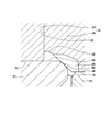
- the constituent material of the intermediate portion 52 between the central portion 27 and the outer portion 50 in the raw material 10 flows upward in the material escape portion 32, but the material escape portion A space 33 is left between the constituent material of the intermediate portion 52 of the raw material 10 and the tooth forming mold 16 inside 32. In this way, the constituent material of the intermediate portion 52 is not restrained inside the material escape portion 32 and is in a free state in the upward direction. Further, as shown in FIG.
- the constituent material of the boss portion 48 of the material 10 flows downward in the recessed portion 36, but the boss portion 48 and the recessed mold 18 are formed inside the recessed portion 36. A space 37 is left between the two. In this way, the constituent material of the boss portion 48 is not constrained inside the recessed portion 36 and is free in the downward direction. At this time, the material 10 has a shape as shown in FIGS.
- FIG. 4 is a main part configuration diagram of the manufacturing apparatus 1 during the forming process of the material 10
- FIG. 5 is an enlarged view around the material escape part 32 in FIG. 6 is a cross-sectional view of the material 10 during the forming process
- FIG. 7 is an external perspective view of the material 10 during the forming process.
- the intermediate portion 52 of the material 10 is in a free state in the vertical direction (axial direction). Therefore, since the constituent material of the raw material 10 has few portions restrained by the respective forming dies, the forming processing of the raw material 10 can be performed while suppressing the forming load applied from the tooth forming die 16 to the raw material 10. Therefore, it is possible to suppress the load on each mold of the outer mold 14, the tooth forming mold 16 and the recessed mold 18.
- the constituent material of the raw material 10 is made to flow in three directions, the direction toward the outer side in the radial direction, the direction toward the inside of the recessed portion 36, and the direction toward the inside of the material escape portion 32, the molding load is reduced. An effect can be aimed at.
- the material 10 when the outer mold 14 and the tooth forming mold 16 are integrally moved downward relative to the recessed mold 18, the material 10 further becomes the tooth forming mold 16. Compressed by Thereby, the constituent material of the raw material 10 further flows in the radial direction (left-right direction in FIG. 8) toward the outside of the raw material 10. Then, the constituent material of the material 10 flows into the tooth profile portion 28 of the tooth forming die 16, and bevel teeth are formed on the outer portion 50 of the material 10, and the molding process of the material 10 is completed. Accordingly, as shown in FIGS. 10 and 11, the differential side gear 12 that is formed in a rotationally symmetrical shape and includes the bevel gear portion 11 can be manufactured. In addition, when the shaping
- the constituent material of the material 10 flows into the material escape portion 32 of the tooth forming die 16 as shown in FIGS.
- An example of a “second protrusion” is formed, and a space 33 is provided between the protrusion 56 and the tooth forming mold 16 inside the material escape portion 32. Further, a space 37 is provided between the boss portion 48 and the recessed shape mold 18 inside the recessed portion 36 of the recessed shape mold 18. Therefore, the constituent material of the raw material 10 is not restrained inside the material escape portion 32 of the tooth forming die 16 and inside the concave portion 36 of the concave shape die 18 until the forming process of the raw material 10 is completed.
- the molding of the material 10 can be performed while suppressing the molding load applied to the material 10 from the tooth forming mold 16 until the molding of the material 10 is completed and the differential side gear 12 is manufactured. Therefore, the load to each shaping
- the resistance when the constituent material of the raw material 10 flows in increases, and the configuration of the raw material 10 in the concave portion 36 is increased.
- the material becomes difficult to flow. Therefore, by adjusting the axial length of the recessed portion 36 of the recessed shape mold 18, the resistance when the constituent material of the material 10 flows in is adjusted, and when the forming process of the material 10 is completed, the boss is surely A space 37 can be provided between the portion 48 and the recessed mold 18.
- a space 47 (see FIG. 9) is provided between the bevel gear portion 11 and the tooth forming die 16 when the forming process of the material 10 is completed.
- the molding load applied to the material 10 from the tooth forming mold 16 can be further suppressed during the molding process of the material 10, so that the load on each molding mold of the outer mold 14, the tooth forming mold 16 and the recessed mold 18 is reduced. Further suppression is possible.
- the differential side gear 12 (the material 10) is lowered to the lower end face 53 (the surface formed in the radial direction) in the central axis direction.
- a cylindrical boss portion 48 formed so as to protrude in a direction (direction in which a load is applied to the material 10 by the compression portion 24) is provided.
- the differential side gear 12 (material 10) is loaded on the material 10 by the compression portion 24 upward from the inner end surface 54 inside the bevel gear portion 11 on the upper end surface (surface formed in the radial direction) in the central axis direction.
- the projection 56 is formed so as to protrude in a direction opposite to the direction in which the first is applied.
- the projection part 56 is formed in the part which does not interfere with the other components (difference pinion gear) etc. which mesh
- FIG. 8 is a main part configuration diagram of the manufacturing apparatus 1 when the forming process of the material 10 is completed, and FIG. 9 is an enlarged view around the material escape part 32 in FIG.
- FIG. 10 is a cross-sectional view of the differential side gear 12, and FIG. 11 is an external perspective view of the differential side gear 12.
- the differential side gear 12 manufactured as described above is subjected to additional processing such as drilling in the central portion 58 (see FIG. 10 and FIG. 11) in the central axis direction (vertical direction in FIG. 10).
- a shaft hole for inserting a shaft (not shown) is formed.
- the constituent material of the material 10 is flowed in three directions, ie, a direction toward the outside in the radial direction, a direction toward the recess 36, and a direction toward the material escape portion 32, the effect of reducing the molding load is increased. .
- the outer shape of the material escape portion 32 becomes smaller in the upward direction. Therefore, the constituent material of the material 10 is less likely to flow into the material escape portion 32. Therefore, when the bevel gear portion 11 is completely formed, the material escape portion 32 is not filled with the constituent material of the material 10, and the protrusion 56 and the tooth forming shape It becomes easy to provide the space 33 between 16. Therefore, the molding load can be prevented from becoming extremely large regardless of the fluidity of the constituent material of the material 10. Therefore, the load on the mold can be suppressed regardless of the fluidity of the constituent material of the material 10, and the life of the mold can be improved.
- both sides in the axial direction are not constrained by the intermediate portion 52 of the material 10 when the material 10 is formed. Therefore, the load applied to the material 10 can be further suppressed.
- the differential side gear 12 can be mass-produced while reducing the manufacturing cost.
Landscapes
- Engineering & Computer Science (AREA)
- Mechanical Engineering (AREA)
- Forging (AREA)
- Gears, Cams (AREA)
Abstract
歯形部品の製造方法において、素材はR形状部と第1の突起部を備え、成形型は第1の窪み部と第2の窪み部とを備え、前記成形型の歯形成形部に前記R形状部を当接させ、前記第1の窪み部に前記第1の突起部を挿入しておき、前記素材に対し荷重を加えて外側部分に歯形部を形成する時に、第2の突起部を形成し、前記荷重が最大となった時に、前記歯形部と前記歯形成形部との間、前記第1の突起部と前記成形型との間、および前記第2の突起部と前記成形型との間に空間を設けておく。
Description
本発明は、鍛造により傘歯車部などの歯形部を備える歯形部品を製造するための歯形部品の製造方法、歯形部品の製造装置、歯形部品に関するものである。
従来から、素材に対して鍛造を行うことにより、歯形部を備える歯形部品を製造することが行われている。このような鍛造においては、円柱状の素材の軸方向から素材を圧縮して素材の構成材料を素材の径方向の外側に向かって流動させて、成形型の内部に素材の構成材料を充満させることにより、外周面に歯形部を備える歯形部品を製造する。
このように素材の軸方向から素材を圧縮すると、まず成形型において素材の径方向の内側部分に素材の構成材料が充満するが、その後、素材の構成材料は素材の径方向の外側に向かって一方向に流動する。そして、更に素材の軸方向から素材を圧縮しようとすると、成形型において既に素材の構成材料が充満した部分の面圧が高くなるので、素材に加える荷重(成形荷重)をさらに大きくする必要がある。そのため、成形型への負荷が大きくなるので、成形型の寿命が短くなってしまう。
ここで、特許文献1には鍛造の技術が開示されている。この特許文献1の技術によれば、リング状素材の外周面を拘束しながらリング状素材を軸方向から加圧機構により加圧し、リング状素材の構成材料を加圧方向に向かって流動させながら成形型の歯形部内に充満させている。そして、さらにリング状素材を軸方向から加圧機構により加圧することにより、成形型の歯形部内に連通する開放空所にリング状素材の構成材料の一部を余肉として押し出している。これにより、一定の圧力下でリング状素材の構成材料を流動させることができ、素材の体積のバラつきによる製品寸法および精度のバラつきを減少できるとしている。
しかしながら、特許文献1の技術によれば、リング状素材の構成材料を成形型の歯形部内に充満させた後に、さらにリング状素材を軸方向から加圧機構により加圧しており、成形荷重が大きくなってしまう。そのため、成形型への負荷が大きくなり、成形型の寿命が短くなってしまう。
そこで、本発明は上記した問題点を解決するためになされたものであり、成形型の寿命の向上を図ることができる歯形部品の製造方法、歯形部品の製造装置、歯形部品を提供すること、を課題とする。
上記課題を解決するためになされた本発明の一態様は、回転対称形状の素材をもとに成形型を用いて製造する歯形部品の製造方法において、前記素材は、径方向の外側部分にR形状部を備え、軸方向の一端面に前記軸方向に突出するようにして周方向に環状に設けられた第1の突起部を備えており、前記成形型は、前記軸方向に窪むようにして前記周方向に環状に設けられた第1の窪み部と、前記第1の窪み部に対して前記素材を挟んだ前記軸
方向の反対側にて前記軸方向に窪むようにして前記周方向に環状に設けられた第2の窪み部とを備え、前記成形型の歯形成形部に前記素材の前記R形状部を当接させ、前記第1の窪み部に前記素材の前記第1の突起部を挿入しておき、前記素材の径方向の中央部分に対し前記軸方向に向かって荷重を加えて前記素材の構成材料を前記径方向の外側に向かって流動させて前記素材の前記外側部分に歯形部を形成する時に、前記第1の突起部の前記素材の構成材料を前記第1の窪み部の内部に向かって前記軸方向に流動させ、かつ、前記中央部分と前記外側部分との間の中間部分の前記素材の構成材料を前記第2の窪み部の内部に向かって前記軸方向に流動させて第2の突起部を形成し、前記荷重が最大となった時に、前記歯形部と前記歯形成形部との間、前記第1の突起部と前記成形型との間、および前記第2の突起部と前記成形型との間に空間を設けておくこと、を特徴とする。
方向の反対側にて前記軸方向に窪むようにして前記周方向に環状に設けられた第2の窪み部とを備え、前記成形型の歯形成形部に前記素材の前記R形状部を当接させ、前記第1の窪み部に前記素材の前記第1の突起部を挿入しておき、前記素材の径方向の中央部分に対し前記軸方向に向かって荷重を加えて前記素材の構成材料を前記径方向の外側に向かって流動させて前記素材の前記外側部分に歯形部を形成する時に、前記第1の突起部の前記素材の構成材料を前記第1の窪み部の内部に向かって前記軸方向に流動させ、かつ、前記中央部分と前記外側部分との間の中間部分の前記素材の構成材料を前記第2の窪み部の内部に向かって前記軸方向に流動させて第2の突起部を形成し、前記荷重が最大となった時に、前記歯形部と前記歯形成形部との間、前記第1の突起部と前記成形型との間、および前記第2の突起部と前記成形型との間に空間を設けておくこと、を特徴とする。
この態様によれば、素材の軸方向に向かって加える荷重が最も大きくなり歯形部を形成し終えた時に、成形型と素材との間に空間を設けており、成形型に素材の構成材料を充満させていない。これにより、この空間内に素材の構成材料が流れる余地を持たせている。そのため、閉塞鍛造のように、成形荷重が極端に大きくなることを防止できる。したがって、成形型への負荷を抑制できるので、当該成形型の寿命を向上させることができる。
また、素材の構成材料を、径方向の外側に向かう方向と、成形型の第1の窪み部に向かう方向と、成形型の第2の窪み部に向かう方向の3つの方向に流動させるので、成形荷重の低減効果が大きくなる。そのため、成形型への負荷を抑制できるので、当該成形型の寿命を向上させることができる。
上記の態様においては、前記第2の窪み部の外形は、前記軸方向に向かって小さくなっていること、が好ましい。
この態様によれば、歯形成形型の第2の窪み部に素材の構成材料が流れ難くなるので、歯形部を形成し終えた時に成形型の窪み部に素材が充満せず、素材と成形型との間に空間が設けられ易くなる。そのため、素材の構成材料の流動性に関わらず、成形荷重が極端に大きくなることを防止できる。したがって、素材の構成材料の流動性に関わらず成形型への負荷を抑制できるので、当該成形型の寿命を向上させることができる。
上記の態様においては、前記第1の窪み部と前記第2の窪み部は、前記軸方向について対称な位置に形成されていること、が好ましい。
この態様によれば、素材の成形加工時において素材の一部にて軸方向の両面を拘束しないので、素材に加える荷重をさらに抑制することができる。
上記の態様においては、前記歯形部品は、差動装置のデフサイドギヤであること、が好ましい。
この態様によれば、デフサイドギヤの製造において成形型の寿命が向上するので、製造コストを低減しつつデフサイドギヤを量産することができる。
上記課題を解決するためになされた本発明の他の態様は、回転対称形状の素材をもとに成形型を用いて製造する歯形部品の製造装置において、前記素材は、径方向の外側部分にR形状部を備え、軸方向の一端面に前記軸方向に突出するようにして周方向に環状に設けられた第1の突起部を備えており、前記成形型は、前記軸方向に窪むようにして前記周方向に環状に設けられた第1の窪み部と、前記第1の窪み部に対して前記素材を挟んだ前記軸方向の反対側にて前記軸方向に窪むようにして前記周方向に環状に設けられた第2の窪み部とを備え、前記成形型の歯形成形部に前記素材の前記R形状部を当接させ、前記第1の窪み部に前記素材の前記第1の突起部を挿入しておき、前記素材の径方向の中央部分に対し前記軸方向に向かって荷重を加えて前記素材の構成材料を前記径方向の外側に向かって流動させて前記素材の前記外側部分に歯形部を形成する時に、前記第1の突起部の前記素材の構成材料を前記第1の窪み部の内部に向かって前記軸方向に流動させ、かつ、前記中央部分と前記外側部分との間の中間部分の前記素材の構成材料を前記第2の窪み部の内部に向かって前記軸方向に流動させて第2の突起部を形成し、前記荷重が最大となった時に、前記歯形部と前記歯形成形部との間、前記第1の突起部と前記成形型との間、および前記第2の突起部と前記成形型との間に空間を設けておくこと、を特徴とする。
この態様によれば、素材の軸方向に向かって加える荷重が最も大きくなり歯形部を形成し終えた時に、成形型と素材との間に空間を設けており、成形型に素材の構成材料を充満させていない。これにより、この空間内に素材の構成材料が流れる余地を持たせている。そのため、閉塞鍛造のように、成形荷重が極端に大きくなることを防止できる。したがって、成形型への負荷を抑制できるので、当該成形型の寿命を向上させることができる。
上記課題を解決するためになされた本発明の他の態様は、回転対称形状の素材をもとに成形型を用いて製造された歯形部品において、前記素材は、径方向の外側部分にR形状部を備え、軸方向の一端面に前記軸方向に突出するようにして周方向に環状に設けられた第1の突起部を備えており、前記成形型は、前記軸方向に窪むようにして前記周方向に環状に設けられた第1の窪み部と、前記第1の窪み部に対して前記素材を挟んだ前記軸方向の反対側にて前記軸方向に窪むようにして前記周方向に環状に設けられた第2の窪み部とを備え、前記成形型の歯形成形部に前記素材の前記R形状部を当接させ、前記第1の窪み部に前記素材の前記第1の突起部を挿入しておき、前記素材の径方向の中央部分に対し前記軸方向に向かって荷重を加えて前記素材の構成材料を前記径方向の外側に向かって流動させて前記素材の前記外側部分に歯形部を形成する時に、前記第1の突起部の前記素材の構成材料を前記第1の窪み部の内部に向かって前記軸方向に流動させ、かつ、前記中央部分と前記外側部分との間の中間部分の前記素材の構成材料を前記第2の窪み部の内部に向かって前記軸方向に流動させて第2の突起部を形成し、前記荷重が最大となった時に、前記歯形部と前記歯形成形部との間、前記第1の突起部と前記成形型との間、および前記第2の突起部と前記成形型との間に空間を設けておくことにより製造されたものであり、前記軸方向の一端面に前記第1の突起部が設けられ、前記軸方向の他端面に前記第2の突起部が設けられており、前記第2の突起部は、前記歯形部に対して前記径方向の内側に設けられていること、を特徴とする。
この態様によれば、素材の軸方向に向かって加える荷重が最も大きくなり歯形部を形成し終えた時に、成形型と素材との間に空間を設けており、成形型に素材の構成材料を充満させていない。これにより、この空間内に素材の構成材料が流れる余地を持たせている。そのため、閉塞鍛造のように、成形荷重が極端に大きくなることを防止できる。したがって、成形型への負荷を抑制できるので、当該成形型の寿命を向上させることができる。
また、第2の突起部は歯形部に対して径方向の内側(歯形部の内径端面の内側)に設けるので、歯形部にて他の歯形部品と噛み合わせる際に、歯形部品の機能性に影響を与えない。
本発明に係る歯形部品の製造方法、歯形部品の製造装置、歯形部品によれば、成形型の寿命の向上を図ることができる。
以下、本発明を具体化した実施形態について、添付図面を参照しつつ詳細に説明する。本実施例では歯形部品として、例えば、車両における差動装置に使用されるデフサイドギヤを例に挙げて説明する。なお、差動装置のデフサイドギヤは、デフケース内において、デフピニオンギヤと噛み合う状態でドライブシャフトにより回転可能に支持されているギヤである。
〔製造装置の説明〕
まず、歯形部品の製造装置1について説明する。製造装置1は、鍛造により回転対称形状の素材10(図3参照)から、傘歯車部11を備えるデフサイドギヤ12(図11参照)を製造するものである。
まず、歯形部品の製造装置1について説明する。製造装置1は、鍛造により回転対称形状の素材10(図3参照)から、傘歯車部11を備えるデフサイドギヤ12(図11参照)を製造するものである。
図1に示すように、製造装置1は、外側成形型14と歯形成形型16と凹み形状型18の各成形型を有する。また、製造装置1は、これらの各成形型の動作を行うための油圧シリンダ等のアクチュエータ(不図示)と、当該アクチュエータの動作を制御する制御装置(不図示)なども有する。なお、図1は、素材10の成形加工前における製造装置1の要部構成図である。
外側成形型14は、円筒状に形成されており、その内周面20の内側に素材10が配置され、さらに凹み形状型18が設けられている。そして、素材10の成形加工時において、外側成形型14は、歯形成形型16と同期しながら下方向(圧縮部24により素材10に荷重を加える方向)に移動する。
歯形成形型16は、圧縮部24と歯形成形部26とを備え、円柱状の圧縮部24の外側に円筒状の歯形成形部26が設けられている。圧縮部24は、素材10の中央部分27に対応する位置に設けられている。そして、歯形成形部26は、下側(外側成形型14や凹み形状型18が設けられる側)に、傘歯の形状を形成した歯形部28を備えている。
また、図2に示すように、歯形成形部26は、歯形部28の内側、すなわち、圧縮部24と歯形部28との間(歯形部28と歯形成形部26の内周面30との間)に、材料逃げ部32を備えている。材料逃げ部32は、上方向(圧縮部24により素材10に荷重を加える方向とは反対方向)に窪むようにして設けられており、外形が上方向に向かって小さくなるように先細りした形状に形成されている。また、材料逃げ部32は、歯形成形部26の内周面30に沿って歯形成形部26の周方向に環状に設けられている。なお、図2は、図1における材料逃げ部32の周辺の拡大図である。また、材料逃げ部32は、本発明における「第2の窪み部」の一例である。
凹み形状型18は、円柱状に形成され、上側(歯形成形型16が設けられる側)に設けられた端面34と、当該端面34から下方向に窪むようにして設けられた凹み部36を備
えており、外側成形型14の内周面20の内側に設けられている。凹み部36は、凹み形状型18の周方向に環状に設けられている。また、径方向(図1の左右方向)について、凹み部36は、歯形成形型16の材料逃げ部32と同じ位置に形成されている。すなわち、材料逃げ部32と凹み部36は、互いに素材10を挟んだ軸方向(図1の上下方向)の反対側に設けられ、軸方向に対称となる位置に設けられている。なお、凹み部36は、本発明における「第1の窪み部」の一例である。
えており、外側成形型14の内周面20の内側に設けられている。凹み部36は、凹み形状型18の周方向に環状に設けられている。また、径方向(図1の左右方向)について、凹み部36は、歯形成形型16の材料逃げ部32と同じ位置に形成されている。すなわち、材料逃げ部32と凹み部36は、互いに素材10を挟んだ軸方向(図1の上下方向)の反対側に設けられ、軸方向に対称となる位置に設けられている。なお、凹み部36は、本発明における「第1の窪み部」の一例である。
〔製造方法の説明〕
次に、以上のような構成を有する製造装置1を使用したデフサイドギヤ12の製造方法について説明する。
次に、以上のような構成を有する製造装置1を使用したデフサイドギヤ12の製造方法について説明する。
まず、図1に示すように、凹み形状型18の端面34が外側成形型14の上側(歯形成形型16が設けられる側)の端面38よりも下側に位置する状態で、外側成形型14の内周面20の内側において、凹み形状型18の端面34の上に素材10を配置する。そして、外側成形型14の端面38に歯形成形部26を配置し、素材10の上端面40(歯形成形型16が設けられる側の端面)に圧縮部24を配置するようにして、歯形成形型16を配置する。これにより、外側成形型14と歯形成形型16と凹み形状型18の各成形型で囲まれた空間内に、素材10を配置する。このとき、素材10は、凹み形状型18の端面34と圧縮部24の端面42との間で挟まれる。
素材10は、回転対称の形状に形成されており、軸方向の一端面として下端面46を備え、軸方向の他端面として上端面40を備えている。そして、上端面40の外径よりも下端面46の外径が小さく形成され、下端面46に下方向に突出するように形成された凸形状のボス部48を備える。ボス部48は、素材10の周方向に環状に形成されている。そして、ボス部48を凹み形状型18の凹み部36の内部に挿入して、素材10を凹み形状型18の端面34の上に配置する。なお、ボス部48を凹み形状型18の凹み部36の内部に挿入することにより、各成形型に対し素材10の径方向(図1の左右方向)の位置決めを行うことができる。また、ボス部48は、本発明における「第1の突起部」の一例である。
また、素材10は、上端面40の外周端部に円周形状のR形状部49を備えている。そして、このR形状部49は、後述するように歯形成形部26の歯形部28が当接する部分である。
次に、図4に示すように、外側成形型14と歯形成形型16とを一体的に(同期させながら)、凹み形状型18に対して相対的に下方向(凹み形状型18が設けられている方向)に移動させる。このとき、歯形成形型16の圧縮部24により素材10の中央部分27に対し下方向に向かって荷重を加えて当該中央部分27を圧縮して、素材10の構成材料を素材10の径方向の外側に(図4の左右方向に)向かって流動させる。そして、素材10のR形状部49に歯形成形部26の歯形部28を当接させ、歯形成形部26の歯形部28によりR形状部49を圧縮していくことにより、素材10の外側部分50に歯形を形成して傘歯車部11を形成していく。
この時、素材10の径方向における中央部分27は圧縮されて厚みが減少し、素材10の構成材料は素材10の外側に向かって流動する。そして、図5に示すように、素材10において中央部分27と外側部分50との間の中間部分52の構成材料は、材料逃げ部32の内部を上方向に向かって流動するが、材料逃げ部32の内部にて素材10の中間部分52の構成材料と歯形成形型16との間に空間33を残している。このようにして、材料逃げ部32の内部で中間部分52の構成材料を拘束せずに上方向に自由な状態としている。また、図4に示すように、素材10のボス部48の構成材料は、凹み部36の内部を下方向に向かって流動するが、凹み部36の内部にてボス部48と凹み形状型18との間に空間37を残している。このようにして、凹み部36の内部でボス部48の構成材料を拘束せずに下方向に自由な状態としている。このとき、素材10は図6と図7に示すような形状になる。
なお、図4は素材10の成形加工中における製造装置1の要部構成図であり、図5は図4における材料逃げ部32の周辺の拡大図である。また、図6は成形加工中における素材10の断面図であり、図7は成形加工中における素材10の外観斜視図である。
このように、素材10の成形加工中において、素材10において中間部分52は、上下方向(軸方向)に自由な状態としている。そのため、素材10の構成材料が各成形型により拘束される部分が少ないので、歯形成形型16から素材10に加える成形荷重を抑制しながら、素材10の成形加工を行うことができる。したがって、外側成形型14や歯形成形型16や凹み形状型18の各成形型への負荷を抑制できる。
また、素材10の構成材料を、径方向の外側に向かう方向と、凹み部36の内部に向かう方向と、材料逃げ部32の内部に向かう方向の3つの方向に流動させるので、成形荷重の低減効果を図ることができる。
そして、図8に示すように、さらに凹み形状型18に対して、相対的に外側成形型14と歯形成形型16とを一体的に下方向に移動させると、素材10がさらに歯形成形型16により圧縮される。これにより、素材10の構成材料が素材10の外側に向かって径方向(図8の左右方向)にさらに流動する。そして、歯形成形型16の歯形部28に素材10の構成材料が流れ込んで素材10の外側部分50に傘歯が形成され、素材10の成形加工が完了する。これにより、図10と図11に示すように、回転対称形状に形成され、傘歯車部11を備えるデフサイドギヤ12を製造することができる。なお、素材10の成形加工が完了する時には、外側成形型14と歯形成形型16とが最も下方向の位置に移動し、成形荷重が最も大きくなる。
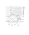
ここで、素材10の成形加工が完了した時に、図8や図9に示すように歯形成形型16の材料逃げ部32の内部に素材10の構成材料が流れ込んで突起部56(本発明における「第2の突起部」の一例)を形成するが、材料逃げ部32の内部において突起部56と歯形成形型16との間に空間33を設けている。また、凹み形状型18の凹み部36の内部において、ボス部48と凹み形状型18との間に空間37を設けている。そのため、素材10の構成材料は、素材10の成形加工が完了するまで、歯形成形型16の材料逃げ部32の内部と凹み形状型18の凹み部36の内部にて拘束されない。したがって、素材10の成形加工が完了してデフサイドギヤ12を製造するまで、歯形成形型16から素材10に加える成形荷重を抑制しながら、素材10の成形加工を行うことができる。ゆえに、外側成形型14や歯形成形型16や凹み形状型18の各成形型への負荷を抑制できる。
また、凹み形状型18の凹み部36は、軸方向の長さ(深さ)を大きくすることにより、素材10の構成材料が流れ込む際の抵抗が大きくなり、当該凹み部36に素材10の構成材料が流れ難くなる。そこで、凹み形状型18の凹み部36の軸方向の長さを調整することにより、素材10の構成材料が流れ込む際の抵抗を調整して、素材10の成形加工が完了した時に、確実にボス部48と凹み形状型18との間に空間37を設けることができる。
また、素材10の成形加工の完了時に、傘歯車部11と歯形成形型16との間に空間47(図9参照)を設けている。これにより、素材10の成形加工時において、歯形成形型16から素材10に加える成形荷重をさらに抑制できるので、外側成形型14や歯形成形
型16や凹み形状型18の各成形型への負荷をさらに抑制できる。
型16や凹み形状型18の各成形型への負荷をさらに抑制できる。
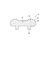
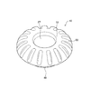
また、素材10の成形加工が完了した時に、図10や図11に示すようにデフサイドギヤ12(素材10)は、中心軸方向の下側の端面53(径方向に形成された面)に下方向(圧縮部24により素材10に荷重を加える方向)に突出するように形成された円筒状のボス部48を備えている。また、デフサイドギヤ12(素材10)は、中心軸方向の上側の端面(径方向に形成された面)に傘歯車部11の内側の内側端面54から上方向(圧縮部24により素材10に荷重を加える方向とは反対方向)に突出するように形成された突起部56を備えている。なお、突起部56は、噛み合わせる相手部品(デフピニオンギヤ)などと干渉しない部分に形成されているので、差動装置に使用されるデフサイドギヤ12の機能性に影響を与えない。
なお、図8は素材10の成形加工の完了時における製造装置1の要部構成図であり、図9は図8における材料逃げ部32の周辺の拡大図である。また、図10はデフサイドギヤ12の断面図であり、図11はデフサイドギヤ12の外観斜視図である。
なお、以上のように製造されたデフサイドギヤ12に対し、その中央部分58(図10と図11参照)に中心軸方向(図10の上下方向)に穴加工などの追加工を行って、ドライブシャフト(不図示)を挿入するための軸穴を形成する。
〔本実施例の効果の説明〕
本実施例によれば、素材10の軸方向に向かって加える成形荷重が最も大きくなり傘歯車部11を形成し終えた時に、成形型と素材10(デフサイドギヤ12)との間に空間33,37,47を設けて成形型に素材10の構成材料を充満させていない。これにより、この空間33,37,47内に素材10の構成材料が流れる余地を持たせている。そのため、閉塞鍛造のように、成形荷重が極端に大きくなることを防止できる。したがって、外側成形型14や歯形成形型16や凹み形状型18の各成形型への負荷を抑制できるので、当該各成形型の寿命を向上させることができる。実験評価の結果の一例として、成形荷重が10%~20%低減した。
本実施例によれば、素材10の軸方向に向かって加える成形荷重が最も大きくなり傘歯車部11を形成し終えた時に、成形型と素材10(デフサイドギヤ12)との間に空間33,37,47を設けて成形型に素材10の構成材料を充満させていない。これにより、この空間33,37,47内に素材10の構成材料が流れる余地を持たせている。そのため、閉塞鍛造のように、成形荷重が極端に大きくなることを防止できる。したがって、外側成形型14や歯形成形型16や凹み形状型18の各成形型への負荷を抑制できるので、当該各成形型の寿命を向上させることができる。実験評価の結果の一例として、成形荷重が10%~20%低減した。
また、素材10の構成材料を、径方向の外側に向かう方向と、凹み部36に向かう方向と、材料逃げ部32に向かう方向の3つの方向に流動させるので、成形荷重の低減効果が大きくなる。
また、材料逃げ部32の外形は上方向に向かって小さくなっている。そのため、材料逃げ部32に素材10の構成材料が流れ難くなるので、傘歯車部11を形成し終えた時に材料逃げ部32に素材10の構成材料が充満せず、突起部56と歯形成形型16との間に空間33が設けられ易くなる。したがって、素材10の構成材料の流動性に関わらず、成形荷重が極端に大きくなることを防止できる。ゆえに、素材10の構成材料の流動性に関わらず、成形型への負荷を抑制できるので、当該成形型の寿命を向上させることができる。
また、材料逃げ部32と凹み部36は軸方向について対称な位置に形成されているので、素材10の成形加工時において素材10の中間部分52にて軸方向の両面を拘束しない。そのため、素材10に加える荷重をさらに抑制することができる。
また、デフサイドギヤ12の製造において各成形型の寿命が向上するので、製造コストを低減しつつデフサイドギヤ12を量産することができる。
なお、上記した実施の形態は単なる例示にすぎず、本発明を何ら限定するものではなく、その要旨を逸脱しない範囲内で種々の改良、変形が可能であることはもちろんである。
1 製造装置
10 素材
11 傘歯車部
12 デフサイドギヤ
14 外側成形型
16 歯形成形型
18 凹み形状型
24 圧縮部
26 歯形成形部
27 (素材の)中央部分
28 (歯形成形部の)歯形部
32 材料逃げ部
33 空間
36 (凹み形状型の)凹み部
37 空間
47 空間
48 ボス部
49 R形状部
50 (素材の)外側部分
52 (素材の)中間部分
56 (デフサイドギヤの)突起部
58 (デフサイドギヤの)中央部分
10 素材
11 傘歯車部
12 デフサイドギヤ
14 外側成形型
16 歯形成形型
18 凹み形状型
24 圧縮部
26 歯形成形部
27 (素材の)中央部分
28 (歯形成形部の)歯形部
32 材料逃げ部
33 空間
36 (凹み形状型の)凹み部
37 空間
47 空間
48 ボス部
49 R形状部
50 (素材の)外側部分
52 (素材の)中間部分
56 (デフサイドギヤの)突起部
58 (デフサイドギヤの)中央部分
Claims (6)
- 回転対称形状の素材をもとに成形型を用いて製造する歯形部品の製造方法において、
前記素材は、径方向の外側部分にR形状部を備え、軸方向の一端面に前記軸方向に突出するようにして周方向に環状に設けられた第1の突起部を備えており、
前記成形型は、前記軸方向に窪むようにして前記周方向に環状に設けられた第1の窪み部と、前記第1の窪み部に対して前記素材を挟んだ前記軸方向の反対側にて前記軸方向に窪むようにして前記周方向に環状に設けられた第2の窪み部とを備え、
前記成形型の歯形成形部に前記素材の前記R形状部を当接させ、前記第1の窪み部に前記素材の前記第1の突起部を挿入しておき、前記素材の径方向の中央部分に対し前記軸方向に向かって荷重を加えて前記素材の構成材料を前記径方向の外側に向かって流動させて前記素材の前記外側部分に歯形部を形成する時に、前記第1の突起部の前記素材の構成材料を前記第1の窪み部の内部に向かって前記軸方向に流動させ、かつ、前記中央部分と前記外側部分との間の中間部分の前記素材の構成材料を前記第2の窪み部の内部に向かって前記軸方向に流動させて第2の突起部を形成し、
前記荷重が最大となった時に、前記歯形部と前記歯形成形部との間、前記第1の突起部と前記成形型との間、および前記第2の突起部と前記成形型との間に空間を設けておくこと、
を特徴とする歯形部品の製造方法。 - 請求項1の歯形部品の製造方法において、
前記第2の窪み部の外形は、前記軸方向に向かって小さくなっていること、
を特徴とする歯形部品の製造方法。 - 請求項1または2の歯形部品の製造方法において、
前記第1の窪み部と前記第2の窪み部は、前記軸方向について対称な位置に形成されていること、
を特徴とする歯形部品の製造方法。 - 請求項1乃至3のいずれか1つの歯形部品の製造方法において、
前記歯形部品は、差動装置のデフサイドギヤであること、
を特徴とする歯形部品の製造方法。 - 回転対称形状の素材をもとに成形型を用いて製造する歯形部品の製造装置において、
前記素材は、径方向の外側部分にR形状部を備え、軸方向の一端面に前記軸方向に突出するようにして周方向に環状に設けられた第1の突起部を備えており、
前記成形型は、前記軸方向に窪むようにして前記周方向に環状に設けられた第1の窪み部と、前記第1の窪み部に対して前記素材を挟んだ前記軸方向の反対側にて前記軸方向に窪むようにして前記周方向に環状に設けられた第2の窪み部とを備え、
前記成形型の歯形成形部に前記素材の前記R形状部を当接させ、前記第1の窪み部に前記素材の前記第1の突起部を挿入しておき、前記素材の径方向の中央部分に対し前記軸方向に向かって荷重を加えて前記素材の構成材料を前記径方向の外側に向かって流動させて前記素材の前記外側部分に歯形部を形成する時に、前記第1の突起部の前記素材の構成材料を前記第1の窪み部の内部に向かって前記軸方向に流動させ、かつ、前記中央部分と前記外側部分との間の中間部分の前記素材の構成材料を前記第2の窪み部の内部に向かって前記軸方向に流動させて第2の突起部を形成し、
前記荷重が最大となった時に、前記歯形部と前記歯形成形部との間、前記第1の突起部と前記成形型との間、および前記第2の突起部と前記成形型との間に空間を設けておくこと、
を特徴とする歯形部品の製造装置。 - 回転対称形状の素材をもとに成形型を用いて製造された歯形部品において、
前記素材は、径方向の外側部分にR形状部を備え、軸方向の一端面に前記軸方向に突出するようにして周方向に環状に設けられた第1の突起部を備えており、前記成形型は、前記軸方向に窪むようにして前記周方向に環状に設けられた第1の窪み部と、前記第1の窪み部に対して前記素材を挟んだ前記軸方向の反対側にて前記軸方向に窪むようにして前記周方向に環状に設けられた第2の窪み部とを備え、前記成形型の歯形成形部に前記素材の前記R形状部を当接させ、前記第1の窪み部に前記素材の前記第1の突起部を挿入しておき、前記素材の径方向の中央部分に対し前記軸方向に向かって荷重を加えて前記素材の構成材料を前記径方向の外側に向かって流動させて前記素材の前記外側部分に歯形部を形成する時に、前記第1の突起部の前記素材の構成材料を前記第1の窪み部の内部に向かって前記軸方向に流動させ、かつ、前記中央部分と前記外側部分との間の中間部分の前記素材の構成材料を前記第2の窪み部の内部に向かって前記軸方向に流動させて第2の突起部を形成し、前記荷重が最大となった時に、前記歯形部と前記歯形成形部との間、前記第1の突起部と前記成形型との間、および前記第2の突起部と前記成形型との間に空間を設けておくことにより製造されたものであり、
前記軸方向の一端面に前記第1の突起部が設けられ、
前記軸方向の他端面に前記第2の突起部が設けられており、
前記第2の突起部は、前記歯形部に対して前記径方向の内側に設けられていること、
を特徴とする歯形部品。
Priority Applications (2)
| Application Number | Priority Date | Filing Date | Title |
|---|---|---|---|
| DE112012000291.1T DE112012000291B4 (de) | 2011-02-24 | 2012-02-10 | Zahnteil-Herstellungsverfahren und Zahnteil-Herstellungsvorrichtung |
| CN201280005942.8A CN103328126B (zh) | 2011-02-24 | 2012-02-10 | 齿形部件制造方法、齿形部件制造装置 |
Applications Claiming Priority (2)
| Application Number | Priority Date | Filing Date | Title |
|---|---|---|---|
| JP2011038975A JP5609713B2 (ja) | 2011-02-24 | 2011-02-24 | 歯形部品の製造方法、歯形部品の製造装置 |
| JP2011-038975 | 2011-02-24 |
Publications (1)
| Publication Number | Publication Date |
|---|---|
| WO2012114910A1 true WO2012114910A1 (ja) | 2012-08-30 |
Family
ID=46718098
Family Applications (1)
| Application Number | Title | Priority Date | Filing Date |
|---|---|---|---|
| PCT/JP2012/053133 Ceased WO2012114910A1 (ja) | 2011-02-24 | 2012-02-10 | 歯形部品の製造方法、歯形部品の製造装置、歯形部品 |
Country Status (5)
| Country | Link |
|---|---|
| US (1) | US9021702B2 (ja) |
| JP (1) | JP5609713B2 (ja) |
| CN (1) | CN103328126B (ja) |
| DE (1) | DE112012000291B4 (ja) |
| WO (1) | WO2012114910A1 (ja) |
Families Citing this family (10)
| Publication number | Priority date | Publication date | Assignee | Title |
|---|---|---|---|---|
| JP5640814B2 (ja) * | 2011-02-24 | 2014-12-17 | アイシン・エィ・ダブリュ株式会社 | 歯形部品の製造方法、歯形部品の製造装置 |
| JP5802252B2 (ja) * | 2013-11-08 | 2015-10-28 | 本田技研工業株式会社 | ギヤの製造方法と、そのための鍛造加工装置 |
| CN103722116B (zh) * | 2014-01-08 | 2015-05-20 | 哈尔滨理工大学 | 齿轮径向旋锻成形装置及方法 |
| CN104014705B (zh) * | 2014-05-13 | 2016-03-16 | 盐城理研精密锻造有限公司 | 一种内星轮成型模具 |
| CN103990750A (zh) * | 2014-06-03 | 2014-08-20 | 张洪磊 | 异型齿星形零件锻造方法及其专用模具 |
| JP6390599B2 (ja) * | 2015-11-30 | 2018-09-19 | マツダ株式会社 | カム要素部材の閉塞鍛造装置および閉塞鍛造方法 |
| CN108994553A (zh) * | 2018-07-06 | 2018-12-14 | 宁波联合蓝光科技有限公司 | 一种直齿轮数控加工方法 |
| CN109550802A (zh) * | 2018-12-14 | 2019-04-02 | 江西福格新能源传动技术有限公司 | 一种差速器齿轮轴向分流冷挤压成形装置与方法 |
| DE102019006975A1 (de) | 2019-10-08 | 2021-04-08 | Neumayer Tekfor Engineering Gmbh | Verfahren zum Erzeugen von Erhebungen in einem Werkstück, Vorrichtung und Produkt |
| CN113617995B (zh) * | 2021-08-27 | 2023-11-17 | 四川凯茨阀门制造有限公司 | 薄壁宽轮幅主减齿毛坯辗扩制坯终锻成型工艺 |
Citations (5)
| Publication number | Priority date | Publication date | Assignee | Title |
|---|---|---|---|---|
| JPH07100578A (ja) * | 1993-08-11 | 1995-04-18 | Nissan Motor Co Ltd | 傘歯車の鍛造方法 |
| JP2000140989A (ja) * | 1998-11-11 | 2000-05-23 | Aida Eng Ltd | ボス部を有するかさ歯車の加工方法及びその金型 |
| JP2007509761A (ja) * | 2003-11-07 | 2007-04-19 | ビショップ イノヴェーション リミテッド | ギヤ歯を鍛造する方法および装置 |
| JP2008036642A (ja) * | 2006-08-01 | 2008-02-21 | Toyota Motor Corp | 歯車の製造方法 |
| JP2009106953A (ja) * | 2007-10-29 | 2009-05-21 | Musashi Seimitsu Ind Co Ltd | 閉塞鍛造装置 |
Family Cites Families (18)
| Publication number | Priority date | Publication date | Assignee | Title |
|---|---|---|---|---|
| US3069756A (en) * | 1958-07-10 | 1962-12-25 | Clark Equipment Co | Method of forming gear blanks |
| CH415247A (de) * | 1963-04-24 | 1966-06-15 | Bayerisches Leichtmetallwerk K | Verfahren und Einrichtung zur Erzeugung von vorzugsweise mittigen Tragbildern an Zahnflanken konischer Zahnräder |
| JPS57177845A (en) | 1981-02-07 | 1982-11-01 | Aida Eng Ltd | Press-forming method for bevel gear and its die |
| JPS6018248A (ja) | 1983-07-11 | 1985-01-30 | Kawasaki Yukou Kk | ベベルギアの鍛造法 |
| JPS61162236A (ja) | 1985-01-10 | 1986-07-22 | Musashi Seimitsu Kogyo Kk | 閉塞鍛造金型装置 |
| DE3701703A1 (de) * | 1987-01-22 | 1988-08-18 | Doege Eckart | Verfahren und vorrichtung zur herstellung von kegelraedern |
| JP2001105085A (ja) * | 1999-10-13 | 2001-04-17 | Toyota Motor Corp | 有脚部材の成形方法、有脚部材を成形するための粗形材、および有脚部材の粗形材の成形装置 |
| JP3687556B2 (ja) * | 2001-03-30 | 2005-08-24 | 日産自動車株式会社 | 傘歯車およびその製造方法 |
| JP2003088935A (ja) * | 2001-09-13 | 2003-03-25 | Sumitomo Heavy Ind Ltd | 外歯歯車の製造方法 |
| US7117598B2 (en) * | 2003-10-21 | 2006-10-10 | American Axle & Manufacturing, Inc. | Net-shaped gear and manufacturing method for forming net-shaped gear employing insert and preform |
| US7827692B2 (en) * | 2006-03-24 | 2010-11-09 | Gkn Sinter Metals, Inc. | Variable case depth powder metal gear and method thereof |
| JP2009050905A (ja) * | 2007-08-29 | 2009-03-12 | Nippon Spindle Mfg Co Ltd | 内歯車の成形方法及び成形装置 |
| JP4942214B2 (ja) * | 2008-05-30 | 2012-05-30 | 武蔵精密工業株式会社 | 傘歯車の鍛造成形方法 |
| US8424407B2 (en) * | 2009-05-20 | 2013-04-23 | Kabushiki Kaisha Pn | Core metal and injection gear, and process for manufacturing core metal |
| JP5640814B2 (ja) * | 2011-02-24 | 2014-12-17 | アイシン・エィ・ダブリュ株式会社 | 歯形部品の製造方法、歯形部品の製造装置 |
| JP5626061B2 (ja) | 2011-03-24 | 2014-11-19 | アイシン・エィ・ダブリュ株式会社 | 歯形部品の製造方法および歯形部品の製造装置 |
| EP2656940B1 (en) | 2011-03-24 | 2018-05-09 | Aisin AW Co., Ltd. | Method for producing tooth profile component |
| JP2013053643A (ja) * | 2011-09-01 | 2013-03-21 | Aisin Aw Co Ltd | 内周凹凸部を有するカップ状部品及びその製造方法及び製造装置 |
-
2011
- 2011-02-24 JP JP2011038975A patent/JP5609713B2/ja active Active
-
2012
- 2012-02-03 US US13/365,831 patent/US9021702B2/en active Active
- 2012-02-10 CN CN201280005942.8A patent/CN103328126B/zh active Active
- 2012-02-10 DE DE112012000291.1T patent/DE112012000291B4/de active Active
- 2012-02-10 WO PCT/JP2012/053133 patent/WO2012114910A1/ja not_active Ceased
Patent Citations (5)
| Publication number | Priority date | Publication date | Assignee | Title |
|---|---|---|---|---|
| JPH07100578A (ja) * | 1993-08-11 | 1995-04-18 | Nissan Motor Co Ltd | 傘歯車の鍛造方法 |
| JP2000140989A (ja) * | 1998-11-11 | 2000-05-23 | Aida Eng Ltd | ボス部を有するかさ歯車の加工方法及びその金型 |
| JP2007509761A (ja) * | 2003-11-07 | 2007-04-19 | ビショップ イノヴェーション リミテッド | ギヤ歯を鍛造する方法および装置 |
| JP2008036642A (ja) * | 2006-08-01 | 2008-02-21 | Toyota Motor Corp | 歯車の製造方法 |
| JP2009106953A (ja) * | 2007-10-29 | 2009-05-21 | Musashi Seimitsu Ind Co Ltd | 閉塞鍛造装置 |
Also Published As
| Publication number | Publication date |
|---|---|
| US9021702B2 (en) | 2015-05-05 |
| JP5609713B2 (ja) | 2014-10-22 |
| US20120216644A1 (en) | 2012-08-30 |
| DE112012000291B4 (de) | 2017-08-31 |
| JP2012171014A (ja) | 2012-09-10 |
| CN103328126B (zh) | 2016-01-06 |
| DE112012000291T5 (de) | 2013-09-05 |
| CN103328126A (zh) | 2013-09-25 |
Similar Documents
| Publication | Publication Date | Title |
|---|---|---|
| JP5609713B2 (ja) | 歯形部品の製造方法、歯形部品の製造装置 | |
| JP5679044B2 (ja) | ドライブプレートの製造装置、ドライブプレートの製造方法 | |
| JP5640814B2 (ja) | 歯形部品の製造方法、歯形部品の製造装置 | |
| JP6292952B2 (ja) | サイジング方法及びサイジング装置 | |
| JP5429762B1 (ja) | クラウニング付きギヤ鍛造成形装置及びその鍛造成形方法 | |
| CN104624918B (zh) | 制造齿轮的方法和用于制造齿轮的锻造装置 | |
| JP2014500396A (ja) | 成形アプリケーション用の粉末金属の軸方向及び径方向の保持部 | |
| JPWO2016031323A1 (ja) | ラックバー及びラックバーの製造方法 | |
| JP5921324B2 (ja) | 歯車の成形方法 | |
| JP5436966B2 (ja) | 焼結歯車の製造方法 | |
| JP6398659B2 (ja) | 歯形部品の製造方法および歯形部品製造装置 | |
| JP2007245220A (ja) | 鍛造加工装置 | |
| JP2007021520A (ja) | 異形斜歯歯車用粉末成形装置および粉末成形方法 | |
| CN203599260U (zh) | 挤压成型模具 | |
| JP2002307126A (ja) | 歯形の成形方法 | |
| JP4900713B2 (ja) | 冷間鍛造による平歯車の製造方法 | |
| CN202963450U (zh) | 粉末冶金的偏心斜齿轮成型模具的结构 | |
| JP6537132B2 (ja) | 焼結部品の製造装置および製造方法 | |
| JP3662902B2 (ja) | 特殊形状円筒状部品のサイジング方法 | |
| CN108480484A (zh) | 组合塔式、带内加强肋板的薄壁环状金属橡胶件冲压模具及其工作方法 | |
| JP5026850B2 (ja) | ワークの製造方法 | |
| JP6732825B2 (ja) | ギヤの製造方法と圧粉成形装置 | |
| JP2012171011A (ja) | 粉末成形品製造方法及び粉末成形品製造装置 | |
| JP6503612B2 (ja) | 圧粉体の製造方法 | |
| JP2006326648A (ja) | 粉末成形金型及び粉末成形方法 |
Legal Events
| Date | Code | Title | Description |
|---|---|---|---|
| 121 | Ep: the epo has been informed by wipo that ep was designated in this application |
Ref document number: 12750162 Country of ref document: EP Kind code of ref document: A1 |
|
| WWE | Wipo information: entry into national phase |
Ref document number: 1120120002911 Country of ref document: DE Ref document number: 112012000291 Country of ref document: DE |
|
| 122 | Ep: pct application non-entry in european phase |
Ref document number: 12750162 Country of ref document: EP Kind code of ref document: A1 |