WO2012114732A1 - ワイヤハーネスにおける短絡回路の形成方法 - Google Patents
ワイヤハーネスにおける短絡回路の形成方法 Download PDFInfo
- Publication number
- WO2012114732A1 WO2012114732A1 PCT/JP2012/001186 JP2012001186W WO2012114732A1 WO 2012114732 A1 WO2012114732 A1 WO 2012114732A1 JP 2012001186 W JP2012001186 W JP 2012001186W WO 2012114732 A1 WO2012114732 A1 WO 2012114732A1
- Authority
- WO
- WIPO (PCT)
- Prior art keywords
- sheet body
- joint connector
- electric wire
- sheet
- short circuit
- Prior art date
- Legal status (The legal status is an assumption and is not a legal conclusion. Google has not performed a legal analysis and makes no representation as to the accuracy of the status listed.)
- Ceased
Links
Images






Classifications
-
- H—ELECTRICITY
- H01—ELECTRIC ELEMENTS
- H01R—ELECTRICALLY-CONDUCTIVE CONNECTIONS; STRUCTURAL ASSOCIATIONS OF A PLURALITY OF MUTUALLY-INSULATED ELECTRICAL CONNECTING ELEMENTS; COUPLING DEVICES; CURRENT COLLECTORS
- H01R31/00—Coupling parts supported only by co-operation with counterpart
- H01R31/08—Short-circuiting members for bridging contacts in a counterpart
-
- H—ELECTRICITY
- H01—ELECTRIC ELEMENTS
- H01R—ELECTRICALLY-CONDUCTIVE CONNECTIONS; STRUCTURAL ASSOCIATIONS OF A PLURALITY OF MUTUALLY-INSULATED ELECTRICAL CONNECTING ELEMENTS; COUPLING DEVICES; CURRENT COLLECTORS
- H01R4/00—Electrically-conductive connections between two or more conductive members in direct contact, i.e. touching one another; Means for effecting or maintaining such contact; Electrically-conductive connections having two or more spaced connecting locations for conductors and using contact members penetrating insulation
- H01R4/70—Insulation of connections
Definitions
- the present invention relates to a method for forming a short circuit by connecting specific wires among a plurality of wires included in the wire harness, and a wire harness including the short circuit in a wire harness of an automobile or the like. It relates to a method for manufacturing.
- the joint connector includes, for example, a plurality of connector terminals that are respectively attached to terminals of specific wires among a plurality of wires bundled together in the wire harness, a connector housing that holds these connector terminals, and the connector housing And a short-circuit conductor that short-circuits the connector terminals by fitting with the connector terminals.
- Patent Document 1 discloses that the joint connector is inserted into a bag-like connector cover made of an elastic material, and the connector cover is opened. It is described that the side end portion is brought into close contact with each electric wire connected to the joint connector using its elastic restoring force.
- the opening end of the connector cover is brought into close contact with the electric wire only by its elastic restoring force, the opening end of the connector cover is securely attached to all the plural electric wires.
- a considerable elastic restoring force is required, and it is not easy to obtain such an elastic restoring force.
- the natural opening diameter of the connector cover (the diameter when not elastically deformed) must be set to be considerably smaller than the maximum outer diameter of the joint connector. Inserting the joint connector into the cover is very troublesome. That is, the operator must forcibly expand the opening of the connector cover with a very large force using a special jig or the like. Also, automation of such operations is extremely difficult.
- the method provided by the present invention includes a short-circuiting step of short-circuiting these electric wires by connecting terminals of a plurality of electric wires included in the wire harness to a common joint connector; A waterproof body manufacturing process for forming a waterproof body that seals and waterproofs the joint connector by closely contacting an end portion of an electric wire connected to the joint connector while covering the joint connector in the periphery.
- the waterproof body manufacturing process includes a first sheet body, an end of each joint connector and each electric wire connected thereto, and a second sheet body around the joint connector and the electric wire.
- An overlapping process in which both side portions in the width direction of the first sheet body and the peripheral portion of the second sheet body are directly brought into contact with each other, and air from the side of the first sheet body in the overlapping state
- the joint connector between the two sheet bodies is brought into close contact with the peripheral portion of the second sheet body and the peripheral portion of the first sheet body by sucking Sealing step for sealing.
- the air suction may be performed from the stage of the superimposing step. That is, the timing at which the air suction is started does not matter before or after completion of the superposition process.
- FIG. 1 shows a wire harness 100 according to this embodiment and a joint connector JC used to form a short circuit of the wire harness 100.
- the joint connector JC is waterproofed by being sealed inside a waterproof body 50 including a first sheet body 52A and a second sheet body 52B as shown in FIG.
- the wire harness 100 according to this embodiment is manufactured by the following process.
- a plurality of electric wires 10 are bundled to form the main wire 12, and a plurality of the electric wires 10 (four in this embodiment) Is drawn out from the trunk line 12 as the branch wire group 14.
- the state where the electric wire 10 was bundled is hold
- Each electric wire 10 is a so-called covered electric wire, and the electric wire 10 has a conductor and an insulating coating that covers the conductor.
- the electric wire side terminals 20 in order to connect the electric wires 10 included in the branch electric wire group 14 to the common joint connector JC, the electric wire side terminals 20 as shown in FIGS. It is installed.
- the electric wire side terminal 20 has a female electrical contact portion 22 and an electric wire crimping portion 24 at the front and rear.
- the electrical contact portion 22 has a hollow rectangular tube-shaped main body and a contact spring piece 26 provided so as to be able to bend in the main body. From the bottom wall of the electrical contact portion 22, a locked piece 28 for locking to the joint connector JC protrudes outward.
- each electric wire 10 included in the branch electric wire group 14 is previously subjected to a treatment for removing the insulating coating and exposing the conductor, and the electric wire crimping portion 24 is connected to the end of the conductor and the vicinity thereof.
- the electric wire crimping portion 24 is connected to the end of the conductor and the vicinity thereof.
- the joint connector JC includes a single short-circuit conductor 30 and an insulating housing 40 for holding the short-circuit conductor 30.
- the short-circuiting conductor 30 is made of a conductive material, and is short-circuited between the electric wire side terminals 20 by being commonly connected to the electric wire side terminals 20.
- the insulating housing 40 is integrally formed of an insulating material such as synthetic resin, and can be held in a state in which the shorting conductor 30 is stored, specifically, the thickness direction of the shorting conductor 30. It has a flat shape.
- the short-circuit conductor 30 is composed of a short-circuit metal plate formed by punching a single metal plate into an appropriate shape, and a plurality of fitting portions 32 and short-circuit portions 34 are integrated.
- Each fitting portion 32 is a male (tab) fitting portion that can be fitted into the female electrical contact portion 22 of each electric wire side terminal 20, and these fitting portions 32 are parallel to the width direction thereof. It is arranged in the direction, that is, the direction orthogonal to the thickness direction of the metal plate for short circuit.
- the short-circuit portion 34 extends in the arrangement direction of the fitting portions 32, and the short ends 34 are connected to the base ends of the fitting portions 32.
- the insulating housing 40 has a pair of side walls that connect the flat top wall 41 and the bottom wall 42 that are parallel to each other, and both ends of the walls 41 and 42 in the width direction (that is, the left end portions and the right end portions). 44 integrally. These walls 41, 42, 44 constitute the outer wall of the insulating housing 40.
- the rear end portion (right end portion in FIGS. 3 to 6) of the outer wall constitutes a conductor holding portion 43.
- the short-circuit portion 34 is held by the conductor holding portion 43 by press-fitting the short-circuit portion 34 of the short-circuiting conductor 30 into the conductor holding portion 43 from the opening 43 a.
- the conductor holding portion 43 has a shape for holding the short-circuit portion 34 of the short-circuit conductor 30. Specifically, it has an outer shape that is slightly larger than the short-circuit portion 34 and extends in the arrangement direction of the fitting portions 32 of the short-circuit conductor 30, and the short-circuit portion 34 is inserted from the rear (left side in FIG. 8). A possible short-circuit metal plate insertion opening 43a is enclosed.
- the short-circuit portion 34 is press-fitted into the conductor holding portion 43 from the insertion port 43a with the fitting portions 32 facing forward. More specifically, protrusions 34 a as shown in FIG. 6 are formed at both ends in the width direction of the short-circuit part 34, and these conductors 34 a dig into the inner side surface of the conductor holding part 43.
- the short-circuit part 34 is fixed to.
- a plurality of (three in the figure) partition walls 45 parallel to the side walls 44 are arranged in the connector width direction at a portion on the front side of the conductor holding portion 43.
- Each partition wall 45 defines a terminal accommodating chamber 47 between another partition wall 45 or a side wall 44 adjacent thereto.
- These terminal accommodating chambers 47 are formed corresponding to the respective fitting portions 32 and receive the electric wire side terminals 20 so as to allow the electric wire side terminals 20 to be fitted into the fitting portions 32. It has a shape, specifically a shape that opens forward and allows the wire-side terminal 20 to be inserted through the opening.
- each fitting portion 32 of the short-circuiting conductor 30 protrudes from the rear, and the electric contact portion 22 of the electric wire side terminal 20 inserted into the terminal accommodating chamber 47 is the fitting portion.
- the electric wire side terminal 20 and the short-circuiting conductor 30 are electrically connected to each other by being engaged with the terminal 32.
- the bottom wall 42 is formed with a lance 46 that is a terminal locking portion at a position corresponding to each terminal accommodating chamber 47.
- each lance 46 has a slit 42a formed in the bottom wall 42, that is, a pair of parallel linear portions extending in the front-rear direction of the connector and the ends of these linear portions are connected to each other in the connector width.
- a claw-like locking portion 46a is formed at the free end.
- the engaging portion 46a is flexibly displaced as shown in FIG. 3 by coming into contact with the inserted electric wire side terminal 20, and allows the electric wire side terminal 20 to pass. By returning, the locked piece 28 of the electric wire side terminal 20 is restrained from the rear.
- the lance 46 has a locking position (position shown in FIG. 4) where the locking portion 46 a locks the electric wire side terminal 20 at a position where the electric wire side terminal 20 is engaged with the fitting portion 32. And a retraction position (position shown in FIG. 3) that retreats to the outside with the elastic deformation of the lance 46 from this locking position, which is the same as the outer surface of the other part of the bottom wall 42 at the locking position. It is located on the surface and protrudes outward from the outer surface of the other part of the bottom wall 42 at the retracted position.
- the wire-side terminal 20 at the end of the wire 10 included in the branch wire group 14 is inserted into the terminal accommodating chamber 47 and is directly fitted into the fitting portion 32 of the short-circuiting conductor 30.
- the short circuit between the electric wire side terminals 20 using the shorting conductor 30 as a connection medium is achieved. That is, the short circuit about the some electric wire 10 with which the said electric wire side terminal 20 was each mounted
- a waterproof body 50 as shown in FIG. 2 is formed around the joint connector JC and an end portion 10a of the electric wire 10 connected thereto (the electric wires 10 included in the branch wire group 14). By sealing the joint connector JC, the short circuit is waterproofed.
- the waterproof body 50 can be efficiently manufactured by the following process, for example.
- This process includes the first sheet body 52A having a dimension sufficiently larger than the planar shape of the joint connector JC, the joint connector JC, and the electric wires 10 connected thereto, as shown in FIG.
- the thickness of the joint connector JC includes the end portion 10a and the second sheet body 52B having a dimension sufficiently larger than the planar shape of the joint connector JC (having a shape larger than the first sheet body 52A in this embodiment).
- the peripheral portion 52a of the first sheet body 52A and the peripheral portion 52b of the second sheet body 52B can directly contact each other around the joint connector JC and the electric wire 10. It is done to become.
- a vacuum forming die 60 as shown in FIG. 7 is used for forming the waterproof body 50.
- the vacuum forming die 60 has a flat upper surface, which forms a forming surface 62.
- a plurality of suction ports 64 are opened on the molding surface 62, and these suction ports 64 are connected to a vacuum pump (not shown) through an air passage formed in the vacuum molding die 60. Air above the suction port 64 is sucked.
- the first sheet body 52B is laid on the molding surface 62 of the vacuum forming mold 60.
- the first sheet body 52A is constituted by a sheet made of, for example, a synthetic resin.
- a number of ventilation holes are provided in the peripheral portion 52a of the first sheet body 52A (the portion protruding outward from the joint connector JC) in order to promote close contact with the second sheet body 52B by air suction described later. May be.
- the diameter of the vent hole is preferably about 3 mm, for example.
- the joint connector JC and the end portion 10a of the electric wire 10 connected to the joint connector JC are placed on the first sheet body 52A in a relative positional relationship such that the first sheet body 52A protrudes outside the joint connector JC.
- the second sheet body 52B is also composed of a synthetic resin, for example, a sheet made of a synthetic resin made of the same material as the first sheet body 52A. Then, the second sheet body 52B covers the joint connector JC and the electric wire 10 connected thereto so that the peripheral portion 52b of the second sheet body 52B is in direct contact with the peripheral portion 52a of the first sheet body 52A. It is done.
- the material of the two sheet bodies 52A and 52B is not particularly limited, but at least the second sheet body 52B is more preferably a thermoplastic resin such as polyvinyl chloride, polyethylene, or polyester. Since the second sheet body 52B made of such a thermoplastic resin is softened by being heated, the thickness of the second sheet body 52B is set to be relatively large in order to ensure the strength of the second sheet body 52B. Even if the flexibility of the second sheet body 52B at room temperature is low, the second sheet body 52B is sufficiently softened to the shape of the joint connector JC and the end portion 10a of the electric wire 10 connected thereto due to the softening. The peripheral portion 52a of the body 52A and the surface of the electric wire 10 can be satisfactorily contacted.
- a thermoplastic resin such as polyvinyl chloride, polyethylene, or polyester. Since the second sheet body 52B made of such a thermoplastic resin is softened by being heated, the thickness of the second sheet body 52B is set to be relatively large in order to ensure the strength of the second sheet
- a heater 66 as shown in FIG. 7 is disposed above the vacuum forming die 60, and the second sheet body 52B is held by the holding portion 68 on the lower surface of the heater 66 and softened.
- the second sheet body 52B is preferably cut off from the heater 66 and placed on the joint connector JC and the end portion 10a of the electric wire 10 connected thereto.
- the suction of air from the suction port 64 may be performed only in the next sealing step, but preferably it is performed from the stage of the superimposing step.
- the suction of the air in the overlapping step holds the first sheet body 52A on the molding surface 62, and further, the second sheet body 52B on the first sheet body 52A and the joint connector JC. Contributes to attraction.
- the distance between the electric wires 10 becomes narrower as the distance from the joint connector JC increases.
- the both sheets can be used regardless of the distance between the electric wires 10.
- the bodies 52 ⁇ / b> A and 52 ⁇ / b> B can be satisfactorily adhered to the surface of each electric wire 10 by the vacuum forming mold 60.
- the contact state between the peripheral portions 52a and 52b of the both sheet bodies 52A and 52B is more reliably maintained by bonding the peripheral portions 52a and 52b to each other.
- the adhesive provided on the sheet body layer for example, the above-described synthetic resin sheet
- the back surface the surface facing the other sheet body. What has an agent layer should just be prepared.
- the adhesive layer strengthens the contact state by adhering the peripheral portions 52a and 52b of the two sheet bodies 52A and 52B.
- a flexible material such as a butyl rubber-based pressure-sensitive adhesive or a thermosetting liquid agent such as an epoxy resin is suitable.
- both the first sheet body 52A and the second sheet body 52B include an adhesive layer. That is, the first sheet body 52A includes a sheet main body layer 54A and an adhesive layer 56A provided on the back surface thereof, and the second sheet body 52B includes a sheet main body layer 54B and an adhesive layer 56B provided on the back surface thereof. have. According to such a combination of sheet bodies 52A and 52B, not only the peripheral portions 52a and 52b are in close contact with each other, but also the peripheral portions 52a and 52b (on the rear end side) as shown in FIG. The close contact with the surface of the portion 10a is also firmly held by adhesion by the adhesive layers 56A and 56B.
- the method described above does not require the troublesome work of inserting the joint connector into the waterproof body while forcibly expanding the opening of the bag-shaped waterproof body with a dedicated jig as in the prior art.
- the operator can surely form the short circuit and waterproof it by a process with very little burden.
- This method is particularly suitable for the case where at least a part of the electric wire side terminal 20 is composed of different metal materials for the electric wire side terminal 10 and the electric wire to which the electric wire side terminal 10 is attached.
- the electric wire side terminal 20 is made of an alloy and is made of copper or a copper alloy, a significant advantage is exhibited. That is, the wire-side terminal 20 composed of different metal materials and the conductor to which the wire-side terminal 20 is attached are likely to corrode when moisture enters the joint portion, so that the short circuit including the wire-side terminal 20 is surely provided. Waterproofing greatly contributes to improvement of connection reliability and extension of life.
- the specific shape and structure of the joint connector used is not particularly limited.
- the connector terminals may be arranged over a plurality of upper and lower stages, or the electric wire side terminal 20 and the short-circuiting conductor 30 may be held in separate connector housings, and these connector housings may be fitted together. .
- the joint connector JC as shown in each figure has a flat shape with a small dimension in the thickness direction
- the joint connector JC and the electric wire 10 connected to the joint connector JC and both sheet bodies 52A and 52B are arranged in the thickness direction.
- the close contact between the peripheral portions 52a and 52b of both the sheet bodies 52A and 52B and the close contact between the peripheral portions 52a and 52b and the surface of the electric wire 10 are more easily and reliably performed.
- the lance 46 as the terminal locking portion is formed on the outer wall (the bottom wall 42 in the figure) as described above, the dimension in the thickness direction is further reduced, and the lance 46 is in its retracted position. In this case, the lance 46 is moved outside by the first sheet body 52A or the second sheet body 52B (the first sheet body 52A in FIG. 8) at the locking position.
- the outer wall (the bottom wall 42 in this embodiment) of the joint connector JC is restrained from the outside by using the first sheet body 52A or the second sheet body 52B that seals the joint connector JC. Therefore, it is possible to prevent the lance 46 from being displaced from the locking position to the retracted position, so that the joint connector JC is not provided with a special structure for double-locking the electric wire side terminal 20, that is, the joint. It is possible to more reliably hold the wire-side terminal 20 by the lance 46 while keeping the shape of the connector JC thin.
- a method capable of easily forming a waterproof short circuit in a wire harness including a plurality of electric wires bundled together includes a short-circuiting step of short-circuiting these electric wires by connecting ends of a plurality of electric wires included in the wire harness to a common joint connector, and the joint around the joint connector.
- the waterproof body manufacturing process includes a first sheet body, an end of each joint connector and each electric wire connected thereto, and a second sheet body around the joint connector and the electric wire.
- the electric wire side terminals are respectively attached to the ends of the specific electric wires
- the joint connector is made of a single metal plate and has a plurality of fitting portions arranged in a direction perpendicular to the thickness direction. Then, each fitting portion is fitted to each of the electric wire side terminals, and the shorting metal plate for short-circuiting the electric wires in the fitted state, and a flat outer shape in the thickness direction of the shorting metal plate
- a plurality of terminal accommodating chambers for holding the wire-side terminals so as to hold the short-circuiting metal plate and allow the wire-side terminals to be fitted into the fitting portions of the short-circuiting metal plate. It is preferred to use an insulating housing that surrounds the housing.
- the joint connector and the end portion of the electric wire connected thereto have a flat shape as a whole (the thickness direction that is perpendicular to the arrangement direction of the electric wires is small), by overlapping both sheet bodies in the thickness direction, It is possible to more reliably and easily join the two sheet bodies.
- the joint connector has an outer wall facing the terminal accommodating chamber, and a terminal locking portion for locking the electric wire side terminal is formed on the outer wall, and the terminal locking portion locks the electric wire side terminal.
- the terminal locking portion is elastically displaceable between the locking position and the retracted position retracted outward from the locking position and projecting outward from the outer wall. It is preferable that the peripheral portions of both sheet bodies are joined together so as to be restrained from the outside by the one sheet body or the second sheet body.
- the terminal engagement portion formed on the outer wall of the joint connector is constrained to the engagement position by using the first sheet body or the second sheet body that is in close contact with the joint connector. It is possible to prevent the stop portion from being displaced from the locking position to the retracted position, and to more reliably hold the state in which the terminal locking portion locks the electric wire side terminal.
- the method according to the present invention can be performed more efficiently by using a vacuum forming die having a forming surface in which a plurality of suction ports for sucking air are opened.
- the superimposing step lays the first sheet body on the molding surface, and the peripheral portion of the first sheet body is the joint connector and The joint connector and the end of the electric wire connected to the first connector are placed on the first sheet so as to protrude outside the end of the electric wire connected thereto, and the second sheet is attached to the second sheet.
- the second sheet body includes a layer made of a thermoplastic resin, and the layer is softened by heating, and the joint connector and the end of the electric wire connected thereto and the first sheet body It is more preferable to cover the peripheral portion of the sheet body.
- the second sheet body is heated and softened so that the second sheet body is connected to the joint connector and the wires connected thereto. While conforming to the shape of the end, the end of the electric wire and the peripheral portion of the first sheet body can be satisfactorily adhered. Therefore, both the setting of the thickness of the second sheet body for ensuring the strength of the second sheet body and the sealing and waterproofing of the joint connector by the close contact between the first and second sheet bodies can be achieved.
- a sheet body layer and a back surface of the sheet body layer It is more preferable that what has an adhesive layer provided in is used, and the peripheral parts of both sheet bodies are adhere
- This method is for at least some of the electric wire side terminals connected to the joint connector, when the electric wire side terminal and the conductor of the electric wire on which the electric wire side terminal is mounted are made of different metal materials, It is particularly effective. If moisture enters the joint portion between the electric wire side terminal composed of different metal materials and the conductor of the electric wire contacting this, there is a risk of accelerating corrosion of the electric wire side terminal or the conductor. It is extremely significant to securely waterproof a short circuit including such a combination of a different metal wire side terminal and a conductor by the method according to the present invention.
- the present invention also provides a method for efficiently producing a wire harness having a short circuit.
- the specific electric wires are short-circuited by applying the step of bundling a plurality of electric wires and the method for forming the short circuit for the terminals of the specific electric wires among the electric wires. Forming a short circuit and producing a waterproof body for sealing the short circuit.
Landscapes
- Manufacturing Of Electric Cables (AREA)
- Connector Housings Or Holding Contact Members (AREA)
Abstract
互いに束ねられる複数の電線を含むワイヤハーネスにおいて、防水された短絡回路を容易に形成することが可能な方法が提供される。この方法は、特定の複数の電線10の端末を共通のジョイントコネクタJCに接続することにより相互短絡させる工程と、防水体50を形成してこの防水体50内にジョイントコネクタJCを密封して防水する工程と、を含む。防水体50は、第1シート体52Aと、ジョイントコネクタJC及びこれにつながる各電線10の端部10aと、第2シート体52Bとを重ね合わされる工程と、その重ね合わせ状態で第1シート体52Aの側からエアを吸引することにより第2シート体52Bの周縁部分52bと第1シート体52Aの周縁部分52aとを密着させるとともに両シート体52A,52Bを電線10の端部10aの表面に密着させる工程と、を含む。
Description
本発明は、自動車等のワイヤハーネスにおいて、当該ワイヤハーネスに含まれる複数の電線のうちの特定の電線同士を接続することにより短絡回路を形成するための方法、及び、短絡回路を含むワイヤハーネスを製造するための方法に関する。
従来、自動車等のワイヤハーネスにおいて短絡回路を形成する方法として、ジョイントコネクタを用いたものが知られている。このジョイントコネクタは、例えば、前記ワイヤハーネスにおいて互いに束ねられる複数の電線のうちの特定の電線の端末にそれぞれ装着される複数のコネクタ端子と、これらのコネクタ端子を保持するコネクタハウジングと、このコネクタハウジングに保持され、前記各コネクタ端子と嵌合することにより当該コネクタ端子同士を短絡させる短絡用導体とを有する。
さらに、前記ジョイントコネクタを用いて形成された短絡回路部を防水するための方法として、特許文献1には、当該ジョイントコネクタを弾性材料からなる袋状のコネクタカバーに挿入し、当該コネクタカバーの開口側端部をその弾性復帰力を利用して前記ジョイントコネクタにつながる各電線に密着させることが記載されている。
しかし、この方法は、コネクタカバーの開口側端部をその弾性復帰力のみによって電線に密着させんとするものであることから、複数本の電線全てに対してコネクタカバーの開口側端部を確実に密着させるには、相当の弾性復帰力が必要であり、このような弾性復帰力を得ることは容易でない。当該弾性復帰力を得るには、コネクタカバーの自然開口径(弾性変形していない状態での径)をジョイントコネクタの最大外径よりもかなり小さく設定しなければならず、このことは、当該コネクタカバー内へのジョイントコネクタの挿入作業を非常に煩わしいものにする。すなわち、作業者は特別な治具等を用いて前記コネクタカバーの開口を非常に大きな力で強制的に拡張させなければならない。また、このような作業の自動化もきわめて困難である。
前記のような難しい作業を避けながら前記コネクタカバーの電線への密着をより確実にする方法として、前記弾性復帰力だけでなく、例えば粘着テープといった補助的な部材を併用することが考えられるが、このような補助的部材の併用は、著しい工数の増加及び構造の複雑化を招く。
本発明の目的は、互いに束ねられる複数の電線を含むワイヤハーネスにおいて、防水された短絡回路を容易に形成することが可能な方法、及び、当該短絡回路をもつワイヤハーネスを容易に製造することを可能にする方法の提供にある。本発明が提供する方法は、前記ワイヤハーネスに含まれる電線のうちの特定の複数の電線の端末を共通のジョイントコネクタに接続することによりこれらの電線同士を短絡させる短絡工程と、前記ジョイントコネクタの周囲にこのジョイントコネクタを覆いながらこのジョイントコネクタにつながる電線の端部に密着することにより当該ジョイントコネクタを密封して防水する防水体を形成する防水体製造工程と、を含む。この方法の特徴として、前記防水体製造工程は、第1シート体と、前記ジョイントコネクタ及びこれにつながる各電線の端部と、第2シート体とを、前記ジョイントコネクタ及び前記電線の周囲において前記第1シート体の幅方向の両側部分と前記第2シート体の周縁部分とが直接接触可能となるように重ね合わされる重ね合わせ工程と、その重ね合わせ状態で前記第1シート体の側からエアを吸引することにより前記第2シート体の周縁部分と前記第1シート体の周縁部分とを密着させるとともに両シート体を前記電線の表面に密着させることで両シート体同士の間に前記ジョイントコネクタを密封する密封工程と、を含む。ここで、前記エアの吸引は、前記重ね合わせ工程の段階から行われていてもよい。すなわち、当該エアの吸引を開始するタイミングは、前記重ね合わせ工程の完了の前後を問わない。
本発明の好ましい実施の形態を、図面を参照しながら説明する。
図1は、この実施形態に係るワイヤハーネス100と、当該ワイヤハーネス100の短絡回路を形成するのに用いられるジョイントコネクタJCとを示す。このジョイントコネクタJCは、図2に示すような第1シート体52A及び第2シート体52Bからなる防水体50の内部に密封されることにより防水される。
この実施の形態にかかるワイヤハーネス100は、次の工程により製造される。
1)幹線12の形成及び特定の電線10の引き出し
複数本の電線10が束ねられることにより幹線12が形成されるとともに、その電線10のうちの複数本(この実施の形態では4本)の電線が分岐電線群14として前記幹線12から引き出される。幹線12については、その周囲に例えばテープが螺旋状に巻き付けられることにより、電線10が束ねられた状態が保持される。前記各電線10には、いわゆる被覆電線が用いられ、当該電線10は導体とこれを被覆する絶縁被覆とをそれぞれ有する。
複数本の電線10が束ねられることにより幹線12が形成されるとともに、その電線10のうちの複数本(この実施の形態では4本)の電線が分岐電線群14として前記幹線12から引き出される。幹線12については、その周囲に例えばテープが螺旋状に巻き付けられることにより、電線10が束ねられた状態が保持される。前記各電線10には、いわゆる被覆電線が用いられ、当該電線10は導体とこれを被覆する絶縁被覆とをそれぞれ有する。
この実施の形態では、前記分岐電線群14に含まれる電線10を共通のジョイントコネクタJCに接続するために、予め当該電線10の端末に図3及び図4に示すような電線側端子20がそれぞれ装着されている。この電線側端子20は、雌型の電気接触部22と電線圧着部24とを前後に有する。前記電気接触部22は、中空角筒状の本体と、この本体内で撓み可能に設けられる接触ばね片26とを有する。この電気接触部22の底壁からは、前記ジョイントコネクタJCに係止されるための被係止片28が外向きに突出している。前記分岐電線群14に含まれる各電線10の端末には、予め、その絶縁被覆を除去して導体を露出させる処理が施されており、前記電線圧着部24は、前記導体の端末及びその近傍の絶縁被覆をそれぞれ抱き込むように曲げ加工されることにより、前記分岐電線群14の端末に圧着され、その導体に電気的に接続されている。
2)ジョイントコネクタJCへの接続(短絡工程)
前記各電線側端子20が図3~図6に示されるようなジョイントコネクタJCに接続されることにより、当該電線側端子20がそれぞれ装着される電線10同士の短絡が行われる。
前記各電線側端子20が図3~図6に示されるようなジョイントコネクタJCに接続されることにより、当該電線側端子20がそれぞれ装着される電線10同士の短絡が行われる。
この実施の形態にかかるジョイントコネクタJCは、単一の短絡用導体30と、この短絡用導体30を保持するための絶縁ハウジング40とを備える。前記短絡用導体30は、導電材料からなり、前記各電線側端子20に共通して接続されることによりこれらの電線側端子20同士を短絡させる。前記絶縁ハウジング40は、合成樹脂等の絶縁材料により全体が一体に成型され、前記短絡用導体30を格納した状態で保持することが可能な形状、具体的には当該短絡用導体30の厚み方向に偏平な形状を有する。
この実施の形態に係る短絡用導体30は、単一の金属板を適当な形状に打ち抜くことにより形成された短絡用金属板からなり、複数の嵌合部32と、短絡部34とを一体に有する。各嵌合部32は、前記各電線側端子20の雌型の電気接触部22に嵌入可能な雄型(タブ)の嵌合部であり、これらの嵌合部32がその幅方向と平行な方向、すなわち短絡用金属板の厚み方向と直交する方向に配列されている。前記短絡部34は、前記嵌合部32の配列方向に延び、この短絡部34に前記各嵌合部32の基端がつながっている。
前記絶縁ハウジング40は、互いに平行な平板状の天壁41及び底壁42と、両壁41,42の幅方向両端部同士(すなわち左側端部同士及び右側端部同士)をそれぞれつなぐ一対の側壁44とを一体に有する。これらの壁41,42,44は絶縁ハウジング40の外壁を構成する。
前記外壁の後端部(図3~図6では右端部)は、導体保持部43を構成する。この導体保持部43内に前記開口部43aから前記短絡用導体30の短絡部34が圧入されることにより、当該短絡部34が当該導体保持部43に保持される。
前記導体保持部43は、前記短絡用導体30の短絡部34を保持する形状を有する。具体的には、前記短絡部34よりも一回り大きく、前記短絡用導体30の嵌合部32の配列方向に延びる外形を有し、前記短絡部34が後方(図8では左方)から挿入可能な短絡用金属板挿入口43aを囲む。この挿入口43aから前記短絡部34が前記各嵌合部32を前方に向けた姿勢で導体保持部43内に圧入される。より詳しくは、当該短絡部34の幅方向両端部に図6に示すような突起34aが形成されており、これらの突起34aが前記導体保持部43の内側面に食い込むことで前記導体保持部43に前記短絡部34が固定されている。
前記導体保持部43よりも前側の部分には、両側壁44と平行な複数(図では3つ)の仕切り壁45がコネクタ幅方向に配列される。各仕切り壁45は、これに隣接する他の仕切り壁45または側壁44との間にそれぞれ端子収容室47を画定する。これらの端子収容室47は、各嵌合部32に対応して形成され、当該嵌合部32に前記各電線側端子20が嵌合されるのを許容するように当該電線側端子20を受け入れる形状、具体的には前方に開口してその開口から前記電線側端子20が挿入可能な形状を有する。各端子収容室47内にはそれぞれ後方から前記短絡用導体30の各嵌合部32が突出しており、当該端子収容室47に挿入された電線側端子20の電気接触部22が前記嵌合部32と嵌合することにより当該電線側端子20と短絡用導体30とが電気的に導通する。
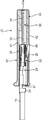
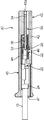
前記底壁42には、前記各端子収容室47に対応する位置に、端子係止部であるランス46が形成されている。各ランス46は、図5に示すように前記底壁42に形成されたスリット42a、すなわち、コネクタの前後方向に延びる互いに平行な一対の直線状部分とこれらの直線状部分の端同士をコネクタ幅方向につなぐ部分とを有する形状のスリット42aにより囲まれていて、当該底壁42の本体に対してその厚み方向に撓む(すなわち弾性変位する)することが可能な自由端部を有し、その自由端部に爪状の係止部46aが形成されている。この係止部46aは、挿入される電線側端子20と接触することにより図3に示すように撓み変位して当該電線側端子20の通過を許容し、その通過後に正規の位置に弾性的に復帰することにより前記電線側端子20の被係止片28を後方から拘束する。
つまり、当該ランス46は、前記係止部46aが前記電線側端子20をこの電線側端子20が前記嵌合部32と嵌合する位置に係止する係止位置(図4に示す位置)と、この係止位置から当該ランス46の弾性変形を伴って外側に退避する退避位置(図3に示す位置)とを有し、前記係止位置では前記底壁42の他の部分の外面と同じ面上に位置し、前記退避位置では当該底壁42の他の部分の外面から外向きに突出する。
従って、このジョイントコネクタJCでは、その端子収容室47内に前記分岐電線群14に含まれる電線10の端末の電線側端子20が挿入されてそのまま短絡用導体30の嵌合部32に嵌合されることにより、当該短絡用導体30を接続媒体とした電線側端子20同士の短絡が達成される。すなわち、当該電線側端子20がそれぞれ装着された複数の電線10についての短絡回路が形成される。
3)短絡回路の防水(防水体製造工程)
前記ジョイントコネクタJC及びこれにつながる電線10(分岐電線群14に含まれる電線10)の端部10aの周囲に、図2に示すような防水体50が形成され、この防水体50の内部に前記ジョイントコネクタJCが密封されることにより、前記短絡回路の防水がなされる。前記防水体50は、例えば次の工程によって効率よく製造されることが可能である。
前記ジョイントコネクタJC及びこれにつながる電線10(分岐電線群14に含まれる電線10)の端部10aの周囲に、図2に示すような防水体50が形成され、この防水体50の内部に前記ジョイントコネクタJCが密封されることにより、前記短絡回路の防水がなされる。前記防水体50は、例えば次の工程によって効率よく製造されることが可能である。
3-1)重ね合わせ工程
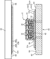
この工程は、図7に示すように前記ジョイントコネクタJCの平面形状よりも十分大きな寸法を有する第1シート体52Aと、前記ジョイントコネクタJC及びこれにつながる各電線10の端部10aと、前記ジョイントコネクタJCの平面形状よりも十分大きな寸法を有する(この実施の形態では第1シート体52Aよりも大きな形状を有する)第2シート体52Bとを前記ジョイントコネクタJCの厚み方向に重ね合わせる工程であり、この重ね合わせは、前記ジョイントコネクタJC及び前記電線10の周囲において前記第1シート体52Aの周縁部分52aと前記第2シート体52Bの周縁部分52bとが直接接触可能となるように行われる。
この工程は、図7に示すように前記ジョイントコネクタJCの平面形状よりも十分大きな寸法を有する第1シート体52Aと、前記ジョイントコネクタJC及びこれにつながる各電線10の端部10aと、前記ジョイントコネクタJCの平面形状よりも十分大きな寸法を有する(この実施の形態では第1シート体52Aよりも大きな形状を有する)第2シート体52Bとを前記ジョイントコネクタJCの厚み方向に重ね合わせる工程であり、この重ね合わせは、前記ジョイントコネクタJC及び前記電線10の周囲において前記第1シート体52Aの周縁部分52aと前記第2シート体52Bの周縁部分52bとが直接接触可能となるように行われる。
この実施の形態では、防水体50の形成のために図7に示すような真空成形用型60が用いられる。この真空成形用型60は、平坦な上面を有し、これが成形面62を構成する。当該成形面62では複数の吸引口64が開口し、これらの吸引口64は前記真空成形用型60の内部に形成されたエア通路を介して図略の真空ポンプに接続され、この真空ポンプは前記吸引口64からその上方のエアを吸引する。
前記第1シート体52Bは、前記真空成形用型60の成形面62の上に敷かれる。この第1シート体52Aは、例えば合成樹脂からなるシートにより構成される。この第1シート体52Aの周縁部分52a(前記ジョイントコネクタJCから外側にはみ出した部分)には、後述のエアの吸引による第2シート体52Bとの密着を促進するために多数の通気孔が設けられてもよい。この場合、前記通気孔の孔径は例えば3mm程度が好適である。
前記ジョイントコネクタJC及びこれにつながる電線10の端部10aは、その外側に前記第1シート体52Aがはみ出すような相対位置関係で当該第1シート体52A上に載置される。
前記第2シート体52Bも、合成樹脂、例えば前記第1シート体52Aと同じ材質の合成樹脂からなるシートにより構成される。そして、当該第2シート体52Bの周縁部分52bが前記第1シート体52Aの周縁部分52aと直接接触するように当該第2シート体52Bが前記ジョイントコネクタJC及びこれにつながる電線10の上に被せられる。
前記両シート体52A,52Bの材質は特に限定されないが、少なくとも第2シート体52Bは例えばポリ塩化ビニル、ポリエチレン、ポリエステルといった熱可塑性樹脂であることがより好ましい。このような熱可塑性樹脂からなる第2シート体52Bは、加熱されることにより軟化するため、当該第2シート体52Bの強度を確保するためにその厚みが比較的大きく設定されていても、すなわち当該第2シート体52Bの常温での柔軟性が低い場合でも、その軟化によって第2シート体52Bは前記ジョイントコネクタJCやこれにつながる電線10の端部10aの形状に十分なじみながら前記第1シート体52Aの周縁部分52aや電線10の表面と良好に接触することができる。
具体的には、例えば図7に示すようなヒータ66が前記真空成形用型60の上方に配置され、このヒータ66の下面上に前記第2シート体52Bが保持部68によって保持されかつ軟化し、その状態で当該ヒータ66から前記第2シート体52Bが切り離されて前記ジョイントコネクタJCおよびこれにつながる電線10の端部10aの上に被せられるのがよい。
また、前記吸引口64からのエアの吸引は、次の密封工程でのみ行われてもよいが、好ましくはこの重ね合わせ工程の段階から行われるのがよい。この重ね合わせ工程でのエアの吸引は、前記成形面62上での第1シート体52Aの保持、さらには、当該第1シート体52A及び前記ジョイントコネクタJC上への前記第2シート体52Bの誘引に寄与する。
3-2)密封工程
前記の重ね合わせ状態で前記第1シート体52Aの側、より詳しくは前記各吸引口64側すなわち第2シート体52Bと反対の側から第1シート体52Aの上側(すなわち第2シート体52B側)のエアが吸引される。これにより、前記第2シート体52Bの周縁部分52bが吸引されて前記第1シート体52Aの周縁部分に密着するとともに、両シート体52A,52Bの(後端側の)周縁部分52a,52bが前記電線10の端部10aに密着し、これにより、前記ジョイントコネクタJCを密封する防水体50が形成される。特に、前記第1シート体52Aの周縁部分52aに多数の通気孔が設けられている場合には、その通気孔を通じて当該周縁部分52a上のエアが直接的に吸引されるから、当該周縁部分52aと第2シート体52Bの周縁部分52bとの密着が促進される。当該通気孔が設けられていない場合は、前記周縁部分52a上のエアが当該周縁部分52aの外側に回り込むようにして前記吸引口64へ吸引される。
前記の重ね合わせ状態で前記第1シート体52Aの側、より詳しくは前記各吸引口64側すなわち第2シート体52Bと反対の側から第1シート体52Aの上側(すなわち第2シート体52B側)のエアが吸引される。これにより、前記第2シート体52Bの周縁部分52bが吸引されて前記第1シート体52Aの周縁部分に密着するとともに、両シート体52A,52Bの(後端側の)周縁部分52a,52bが前記電線10の端部10aに密着し、これにより、前記ジョイントコネクタJCを密封する防水体50が形成される。特に、前記第1シート体52Aの周縁部分52aに多数の通気孔が設けられている場合には、その通気孔を通じて当該周縁部分52a上のエアが直接的に吸引されるから、当該周縁部分52aと第2シート体52Bの周縁部分52bとの密着が促進される。当該通気孔が設けられていない場合は、前記周縁部分52a上のエアが当該周縁部分52aの外側に回り込むようにして前記吸引口64へ吸引される。
一方、前記電線10同士の間隔は、ジョイントコネクタJCから離れるに従って狭くなっているが、図9(a)(b)に示されるように、当該電線10同士の間隔の大小にかかわらず前記両シート体52A,52Bは前記真空成形用型60によって各電線10の表面に良好に密着することができる。
前記両シート体52A,52Bの周縁部分52a,52b同士の密着状態は、当該周縁部分52a,52b同士が接着されることで、より確実に保持される。具体的には、前記両シート体52A,52Bのうちの少なくとも一方について、シート本体層(例えば上述した合成樹脂製のシート)とその裏面(相手方のシート体に対向する面)上に設けられる接着剤層とを有するものが、用意されればよい。その接着剤層は両シート体52A,52Bの周縁部分52a,52b同士を接着することでその密着状態を強固にする。当該接着剤層には、例えば、ブチルゴム系の粘着剤のような柔軟性に富むものや、エポキシ樹脂等の熱硬化性の液状剤が好適である。
図7~図9に示す例では、第1シート体52A及び第2シート体52Bの双方に接着剤層を含むものが用いられている。すなわち、第1シート体52Aは、シート本体層54A及びその裏面上に設けられる接着剤層56Aを有し、第2シート体52Bは、シート本体層54B及びその裏面上に設けられる接着剤層56Bを有している。このようなシート体52A,52Bの組み合わせによれば、その周縁部分52a,52b同士の密着だけでなく、図9に示すような(後端側の)周縁部分52a,52bと各電線10の端部10aの表面との密着も前記接着剤層56A,56Bによる接着でそれぞれ強固に保持される。
以上示した方法は、従来のように袋状の防水体の開口を専用の治具で強制的に拡開しながら当該防水体内にジョイントコネクタを挿入するといった面倒な作業を要しない。作業者はきわめて負担の少ない工程で確実に短絡回路の形成及びその防水を実行できる。
この方法は、特に、前記電線側端子20のうちの少なくとも一部について、当該電線側端子10及びこれが装着される電線の導体が互いに異なる金属材料で構成される場合、例えば当該導体がアルミニウムまたはアルミニウム合金からなって前記電線側端子20が銅または銅合金からなる場合に、顕著な優位性を発揮する。すなわち、互いに異種の金属材料で構成された電線側端子20及びこれが装着される導体は、その接合部分に水分が浸入すると腐食が進行し易いから、当該電線側端子20を含む短絡回路を確実に防水することは、接続信頼性の向上及び寿命の延長に大きく寄与する。
本発明において、用いられるジョイントコネクタの具体的な形状及び構造は特に限定されない。例えば、コネクタ端子が上下複数段にわたって配列されたものでもよいし、電線側端子20及び短絡用導体30がそれぞれ別のコネクタハウジングに保持されていてこれらのコネクタハウジング同士が嵌合されるものでもよい。
しかし、各図に示すようなジョイントコネクタJCは、その厚み方向の寸法が小さい偏平な形状を有するから、その厚み方向に当該ジョイントコネクタJC及びこれにつながる電線10と両シート体52A,52Bとが重ね合わされることにより、当該両シート体52A,52Bの周縁部分52a,52b同士の密着及び当該周縁部分52a,52bと前記電線10の表面との密着がより容易にかつ確実に行われる。
特に、前記のように外壁(図では底壁42)に端子係止部であるランス46が形成されるものでは、厚み方向の寸法がさらに削減されるのに加え、このランス46がその退避位置において当該外壁から外向きに突出するものを用いる場合には、このランス46を前記係止位置で前記第1シート体52Aまたは前記第2シート体52B(図8では第1シート体52A)によって外側から拘束するように両シート体の周縁部分52a,52b同士の接合を行うことにより、簡単な構造でジョイントコネクタJCでの接続信頼性を高めることができる。すなわち、この方法では、前記ジョイントコネクタJCを密封する第1シート体52Aまたは第2シート体52Bを利用して当該ジョイントコネクタJCの外壁(この実施の形態では底壁42)を外側から拘束することにより、ランス46が前記係止位置から前記退避位置に変位するのを抑止できるから、ジョイントコネクタJCに電線側端子20を二重係止するための特別な構造を付与することなく、すなわち当該ジョイントコネクタJCの形状を薄型形状に維持したまま、ランス46による電線側端子20の係止をより確実に保持することが可能である。
以上のように、本発明によれば、互いに束ねられる複数の電線を含むワイヤハーネスにおいて、防水された短絡回路を容易に形成することが可能な方法が提供される。この方法は、前記ワイヤハーネスに含まれる電線のうちの特定の複数の電線の端末を共通のジョイントコネクタに接続することによりこれらの電線同士を短絡させる短絡工程と、前記ジョイントコネクタの周囲にこのジョイントコネクタを覆いながらこのジョイントコネクタにつながる電線の端部に密着することにより当該ジョイントコネクタを密封して防水する防水体を形成する防水体製造工程と、を含む。この方法の特徴として、前記防水体製造工程は、第1シート体と、前記ジョイントコネクタ及びこれにつながる各電線の端部と、第2シート体とを、前記ジョイントコネクタ及び前記電線の周囲において前記第1シート体の幅方向の両側部分と前記第2シート体の周縁部分とが直接接触可能となるように重ね合わされる重ね合わせ工程と、その重ね合わせ状態で前記第1シート体の側からエアを吸引することにより前記第2シート体の周縁部分と前記第1シート体の周縁部分とを密着させるとともに両シート体を前記電線の表面に密着させることで両シート体同士の間に前記ジョイントコネクタを密封する密封工程と、を含む。ここで、前記エアの吸引は、前記重ね合わせ工程の段階から行われていてもよい。すなわち、当該エアの吸引を開始するタイミングは、前記重ね合わせ工程の完了の前後を問わない。
この方法では、複数の電線の端部がジョイントコネクタに接続されることにより短絡回路が形成されるのに加え、第1シート体、前記ジョイントコネクタ及びこれにつながる各電線の端部、及び第2シート体がこの順に重ねられた状態で、第1シート体の側からエアが吸引されることにより、両シート体間に前記ジョイントコネクタが密封された構造の構築、すなわち、防水体の製造が達成される。従って、従来のように袋状の防水体の開口を専用の治具で強制的に拡開しながら当該防水体内にジョイントコネクタを挿入するといった面倒な作業は不要であり、作業者の負担の少ない工程で確実に短絡回路の形成及びその防水が達成される。
この方法では、前記特定の電線の端末にそれぞれ電線側端子が装着される一方、前記ジョイントコネクタとして、単一の金属板からなり、その厚み方向と直交する方向に並ぶ複数の嵌合部を有して各嵌合部が前記各電線側端子とそれぞれ嵌合され、その嵌合状態で当該電線同士を短絡させる短絡用金属板と、この短絡用金属板の厚み方向に偏平な外形を有し、当該短絡用金属板を保持するとともに、当該短絡用金属板の各嵌合部に前記各電線側端子が嵌合されるのを許容するように当該各電線側端子を受け入れる複数の端子収容室を囲む絶縁ハウジングと、を有するものが用いられるのが、好ましい。このジョイントコネクタ及びこれにつながる電線の端部は全体として偏平な(電線の配列方向と直交する方向である厚み方向が小さい)形状を有するので、その厚み方向に両シート体を重ね合わせることにより、両シート体同士の接合をより確実かつ容易に行うことが可能である。
さらに、前記ジョイントコネクタは、前記端子収容室に臨む外壁を有してこの外壁に前記電線側端子を係止する端子係止部が形成され、この端子係止部は前記電線側端子を係止する係止位置とこの係止位置から外側に退避して前記外壁から外向きに突出する退避位置との間で弾性変位可能なものであり、この端子係止部が前記係止位置で前記第1シート体または前記第2シート体によって外側から拘束されるように両シート体の周縁部分同士の接合が行われることが、好ましい。この方法では、前記ジョイントコネクタに密着する第1シート体または第2シート体を利用して当該ジョイントコネクタの外壁に形成された端子係止部を前記係止位置に拘束することにより、当該端子係止部が当該係止位置から前記退避位置に変位するのを抑止して当該端子係止部が電線側端子を係止する状態をより確実に保持することが可能になる。
本発明に係る方法は、エアを吸引するための複数の吸引口が開口する成形面をもつ真空成形用型を用いることにより、さらに効率よく行われることが可能である。具体的に、この真空成形用型を用いた場合には、前記重ね合わせ工程が、前記成形面上に前記第1シート体を敷くことと、前記第1シート体の周縁部分が前記ジョイントコネクタ及びこれにつながる電線の端部の外側にはみ出すように当該第1シート体の上に当該ジョイントコネクタ及びこれにつながる電線の端部を載せることと、前記第2シート体をこの第2シート体が前記ジョイントコネクタ及びこれにつながる電線の端部の周囲で前記第1シート体の周縁部分に重なるように前記ジョイントコネクタ及びこれにつながる電線の端部の上に被せることと、により行われ、前記密封工程が、前記真空成形用型の吸引口からエアを吸引することにより行われる。
前記第2シート体については、当該第2シート体が熱可塑性樹脂からなる層を含み、この層が加熱されることにより軟化した状態で前記ジョイントコネクタ及びこれにつながる電線の端部と前記第1シート体の周縁部分とに被せられるのが、より好ましい。この方法では、前記第2シート体の厚みが比較的大きくて常温での柔軟性が低い場合でも、これを加熱して軟化させることにより当該第2シート体を前記ジョイントコネクタ及びこれにつながる電線の端部の形状になじませながら当該電線の端部及び前記第1シート体の周縁部分に良好に密着させることができる。従って、第2シート体の強度を確保するための当該第2シート体の厚みの設定と、第1及び第2シート体同士の密着によるジョイントコネクタの密封及び防水とを両立させることができる。
前記ジョイントコネクタの密封による短絡回路の防水をより確実に行うには、前記第1シート体及び前記第2シート体のうちの少なくとも一方のシート体として、シート本体層及びこのシート本体層の裏面上に設けられる接着剤層とを有するものが用いられ、当該接着剤層により両シート体の周縁部分同士が接着されることが、より好ましい。さらには、両シート体に前記シート体及び前記接着剤層を有するものが用いられ、それぞれの接着剤層により両シート体が前記ジョイントコネクタにつながる電線の端部の表面にそれぞれ接着されることが、より好ましい。
この方法は、前記ジョイントコネクタに接続される電線側端子のうちの少なくとも一部の電線側端子について、当該電線側端子及びこれが装着される電線の導体が互いに異なる金属材料で構成される場合に、特に有効である。このように互いに異種の金属材料で構成された電線側端子とこれに接触する電線の導体との接合部分に水分が浸入すると、当該電線側端子や当該導体の腐食を促進するおそれがあるから、このような異種金属の電線側端子と導体との組み合わせを含む短絡回路を本発明に係る方法によって確実に防水することは、極めて意義が高い。
また本発明は、短絡回路をもつワイヤハーネスを効率よく製造するための方法を提供する。この製造方法は、複数本の電線を束ねる工程と、その電線のうちの特定の複数の電線の端末について前記の短絡回路を形成するための方法を適用することにより当該特定の電線同士を短絡させる短絡回路を形成し、かつ、これを密封する防水体を製造する工程と、を含む。
Claims (8)
- 互いに束ねられる複数の電線を含むワイヤハーネスにおいて、防水された短絡回路を形成するための方法であって、
前記ワイヤハーネスに含まれる電線のうちの特定の複数の電線の端末を共通のジョイントコネクタに接続することによりこれらの電線同士を短絡させる短絡工程と、
前記ジョイントコネクタの周囲にこのジョイントコネクタを覆いながらこのジョイントコネクタにつながる電線の端部に密着することにより当該ジョイントコネクタを密封して防水する防水体を形成する防水体製造工程と、を含み、
前記防水体製造工程は、第1シート体と、前記ジョイントコネクタ及びこれにつながる各電線の端部と、第2シート体とを、前記ジョイントコネクタ及びこれにつながる電線の端部の周囲において前記第1シート体の周縁部分と前記第2シート体の周縁部分とが直接接触可能となるように重ね合わされる重ね合わせ工程と、その重ね合わせ状態で前記第1シート体の側からエアを吸引することにより前記第2シート体の周縁部分と前記第1シート体の周縁部分とを密着させるとともに両シート体を前記電線の端部の表面に密着させることで前記両シート体同士の間に前記ジョイントコネクタを密封する密封工程と、を含む、ワイヤハーネスにおける短絡回路の形成方法。 - 請求項1記載のワイヤハーネスにおける短絡回路の形成方法において、
前記特定の電線の端末にそれぞれ電線側端子が装着される一方、前記ジョイントコネクタとして、単一の金属板からなり、その厚み方向と直交する方向に並ぶ複数の嵌合部を有して各嵌合部が前記各電線側端子とそれぞれ嵌合され、その嵌合状態で当該電線同士を短絡させる短絡用金属板と、この短絡用金属板の厚み方向に偏平な外形を有し、当該短絡用金属板を保持するとともに、当該短絡用金属板の各嵌合部に前記各電線側端子が嵌合されるのを許容するように当該各電線側端子を受け入れる複数の端子収容室を囲む絶縁ハウジングと、を有するものが用いられ、その厚み方向に両シート体が重ね合わされる、ワイヤハーネスにおける短絡回路の形成方法。 - 請求項2記載のワイヤハーネスにおける短絡回路の形成方法において、
前記ジョイントコネクタは、前記端子収容室に臨む外壁を有してこの外壁に前記電線側端子を係止する端子係止部が形成され、この端子係止部は前記電線側端子を係止する係止位置とこの係止位置から外側に退避して前記外壁から外向きに突出する退避位置との間で弾性変位可能なものであり、この端子係止部をその係止位置で前記第1シート体または前記第2シート体が外側から拘束するように両シート体の周縁部分同士の接合が行われる、ワイヤハーネスにおける短絡回路の形成方法。 - 請求項1または2記載のワイヤハーネスにおける短絡回路の形成方法において、
前記重ね合わせ工程は、エアを吸引するための複数の吸引口が開口する成形面をもつ真空成形用型の当該成形面上に前記第1シート体を敷くことと、前記第1シート体の周縁部分が前記ジョイントコネクタ及びこれにつながる電線の端部の外側にはみ出すように当該第1シート体の上に当該ジョイントコネクタ及びこれにつながる電線の端部を載せることと、前記第2シート体をこの第2シート体が前記ジョイントコネクタ及びこれにつながる電線の端部の周囲で前記第1シート体の周縁部分に重なるように前記ジョイントコネクタ及びこれにつながる電線の端部の上に被せることと、を含み、前記密封工程は、前記真空成形用型の吸引口からエアを吸引することを含む、ワイヤハーネスにおける短絡回路の形成方法。 - 請求項4記載のワイヤハーネスにおける短絡回路の形成方法において、
前記第2シート体が熱可塑性樹脂からなる層を含み、この層が前記重ね合わせ工程において加熱されることにより軟化した状態で当該第2シート体が前記ジョイントコネクタ及びこれにつながる電線の端部と前記第1シート体の周縁部分とに被せられる、ワイヤハーネスにおける短絡回路の形成方法。 - 請求項1~5のうちのいずれか1項に記載のワイヤハーネスにおける短絡回路の形成方法において、
前記第1シート体及び前記第2シート体のうちの少なくとも一方について、シート本体層及びこのシートの裏面上に設けられる接着剤層を有するものが用いられ、当該接着剤層により両シート体の周縁部分同士が接着される、ワイヤハーネスにおける短絡回路の形成方法。 - 請求項6記載のワイヤハーネスにおける短絡回路の形成方法において、
前記第1シート体及び前記第2シート体の双方が前記シート本体層及び前記接着剤層を有し、各接着剤層により両シート体が前記電線の端部の表面にそれぞれ接着される、ワイヤハーネスにおける短絡回路の形成方法。 - 短絡回路をもつワイヤハーネスを製造するための方法であって、
複数本の電線を束ねる工程と、
その電線のうちの特定の複数の電線の端末について請求項1~7のうちのいずれか1項に記載の方法を適用することにより、当該特定の電線同士を短絡させる短絡回路を形成し、かつ、これを密封する防水体を製造する工程と、を含む、短絡回路をもつワイヤハーネスの製造方法。
Applications Claiming Priority (2)
| Application Number | Priority Date | Filing Date | Title |
|---|---|---|---|
| JP2011038020A JP5732901B2 (ja) | 2011-02-24 | 2011-02-24 | ワイヤハーネスにおける短絡回路の形成方法 |
| JP2011-038020 | 2011-02-24 |
Publications (1)
| Publication Number | Publication Date |
|---|---|
| WO2012114732A1 true WO2012114732A1 (ja) | 2012-08-30 |
Family
ID=46720524
Family Applications (1)
| Application Number | Title | Priority Date | Filing Date |
|---|---|---|---|
| PCT/JP2012/001186 Ceased WO2012114732A1 (ja) | 2011-02-24 | 2012-02-22 | ワイヤハーネスにおける短絡回路の形成方法 |
Country Status (2)
| Country | Link |
|---|---|
| JP (1) | JP5732901B2 (ja) |
| WO (1) | WO2012114732A1 (ja) |
Cited By (1)
| Publication number | Priority date | Publication date | Assignee | Title |
|---|---|---|---|---|
| WO2022209626A1 (ja) * | 2021-03-29 | 2022-10-06 | 住友電装株式会社 | 配線部材 |
Families Citing this family (2)
| Publication number | Priority date | Publication date | Assignee | Title |
|---|---|---|---|---|
| PT106994A (pt) | 2013-06-09 | 2014-12-09 | Active Space Technologies Actividades Aeroespaciais Lda | Método e sistema de monitorização de envelhecimento de cablagens eléctricas |
| JP2015069748A (ja) * | 2013-09-27 | 2015-04-13 | 住友電装株式会社 | コネクタ付ワイヤハーネスの防水構造 |
Citations (7)
| Publication number | Priority date | Publication date | Assignee | Title |
|---|---|---|---|---|
| JPS63157163U (ja) * | 1987-04-01 | 1988-10-14 | ||
| JPH02212125A (ja) * | 1988-10-20 | 1990-08-23 | Yazaki Corp | 導体接続部の製造方法 |
| JPH09102332A (ja) * | 1995-07-31 | 1997-04-15 | Yazaki Corp | フラット回路体のジョイント部及びその製造方法 |
| JPH11111065A (ja) * | 1997-09-30 | 1999-04-23 | Yazaki Corp | 回路体及びその製造方法 |
| JP2009207299A (ja) * | 2008-02-28 | 2009-09-10 | Sumitomo Wiring Syst Ltd | 車両用ワイヤハーネスのスプライス収容構造 |
| JP2010177037A (ja) * | 2009-01-29 | 2010-08-12 | Autonetworks Technologies Ltd | アース接続用配線材、これに用いられるジョイントコネクタ、及びアース接続用配線材が組み込まれたワイヤハーネス |
| JP2011165376A (ja) * | 2010-02-05 | 2011-08-25 | Autonetworks Technologies Ltd | ワイヤハーネスの短絡部の製造方法、及びワイヤハーネスの短絡部 |
-
2011
- 2011-02-24 JP JP2011038020A patent/JP5732901B2/ja not_active Expired - Fee Related
-
2012
- 2012-02-22 WO PCT/JP2012/001186 patent/WO2012114732A1/ja not_active Ceased
Patent Citations (7)
| Publication number | Priority date | Publication date | Assignee | Title |
|---|---|---|---|---|
| JPS63157163U (ja) * | 1987-04-01 | 1988-10-14 | ||
| JPH02212125A (ja) * | 1988-10-20 | 1990-08-23 | Yazaki Corp | 導体接続部の製造方法 |
| JPH09102332A (ja) * | 1995-07-31 | 1997-04-15 | Yazaki Corp | フラット回路体のジョイント部及びその製造方法 |
| JPH11111065A (ja) * | 1997-09-30 | 1999-04-23 | Yazaki Corp | 回路体及びその製造方法 |
| JP2009207299A (ja) * | 2008-02-28 | 2009-09-10 | Sumitomo Wiring Syst Ltd | 車両用ワイヤハーネスのスプライス収容構造 |
| JP2010177037A (ja) * | 2009-01-29 | 2010-08-12 | Autonetworks Technologies Ltd | アース接続用配線材、これに用いられるジョイントコネクタ、及びアース接続用配線材が組み込まれたワイヤハーネス |
| JP2011165376A (ja) * | 2010-02-05 | 2011-08-25 | Autonetworks Technologies Ltd | ワイヤハーネスの短絡部の製造方法、及びワイヤハーネスの短絡部 |
Cited By (6)
| Publication number | Priority date | Publication date | Assignee | Title |
|---|---|---|---|---|
| WO2022209626A1 (ja) * | 2021-03-29 | 2022-10-06 | 住友電装株式会社 | 配線部材 |
| JP2022152925A (ja) * | 2021-03-29 | 2022-10-12 | 住友電装株式会社 | 配線部材 |
| JP2024113003A (ja) * | 2021-03-29 | 2024-08-21 | 住友電装株式会社 | 配線部材 |
| JP7625930B2 (ja) | 2021-03-29 | 2025-02-04 | 住友電装株式会社 | 配線部材 |
| JP7761087B2 (ja) | 2021-03-29 | 2025-10-28 | 住友電装株式会社 | 配線部材 |
| US12463373B2 (en) | 2021-03-29 | 2025-11-04 | Sumitomo Wiring Systems, Ltd. | Wiring member |
Also Published As
| Publication number | Publication date |
|---|---|
| JP2012174632A (ja) | 2012-09-10 |
| JP5732901B2 (ja) | 2015-06-10 |
Similar Documents
| Publication | Publication Date | Title |
|---|---|---|
| JP5672158B2 (ja) | コネクタの製造方法 | |
| JP5792011B2 (ja) | フラットケーブル防水コネクタ構造、及びその接続方法 | |
| JP5448756B2 (ja) | シールドフラットケーブル及びその接続構造 | |
| US9378867B2 (en) | Terminal-fitted wire, terminal-fitted wire manufacturing method and corrosion resistant member | |
| CN105453342B (zh) | 压接端子相对于电线的连接结构 | |
| WO2013039253A1 (en) | Connector terminal | |
| JP2015069748A (ja) | コネクタ付ワイヤハーネスの防水構造 | |
| CN105048117A (zh) | 端子连接结构和端子连接方法 | |
| JP4391268B2 (ja) | 防水圧接コネクタとその製造方法 | |
| JP2002170627A (ja) | 防水コネクタ及びその製造方法 | |
| CN106340750A (zh) | 带连接器的电线、和带连接器的电线的制造方法 | |
| JP5732901B2 (ja) | ワイヤハーネスにおける短絡回路の形成方法 | |
| JP2012009335A (ja) | 端子金具の製造方法 | |
| JP5609685B2 (ja) | ワイヤハーネスに設けられるシールド体の製造方法 | |
| US9219327B2 (en) | Waterproof flat cable connector and method for manufacturing same | |
| WO2021006052A1 (ja) | 配線モジュール、蓄電モジュール、バスバー、および蓄電モジュールの製造方法 | |
| JP2013134963A (ja) | 防水コネクタの製造方法 | |
| JP2013134965A (ja) | 防水コネクタの製造方法及び防水コネクタ | |
| JP2013134964A (ja) | 防水コネクタの製造方法及び防水コネクタ | |
| JP2018092734A (ja) | 端子付き電線、端子、ワイヤハーネス | |
| JP3110998B2 (ja) | フラット回路体のジョイント部及びその製造方法 | |
| WO2009084350A1 (ja) | アース接続具 | |
| JP5800204B2 (ja) | 銅電線とアルミ電線の接続構造 | |
| JP5510738B2 (ja) | コネクタ | |
| JP2002325325A (ja) | 配線材及びその製造方法 |
Legal Events
| Date | Code | Title | Description |
|---|---|---|---|
| 121 | Ep: the epo has been informed by wipo that ep was designated in this application |
Ref document number: 12750189 Country of ref document: EP Kind code of ref document: A1 |
|
| NENP | Non-entry into the national phase |
Ref country code: DE |
|
| 122 | Ep: pct application non-entry in european phase |
Ref document number: 12750189 Country of ref document: EP Kind code of ref document: A1 |