WO2012114550A1 - 片リップ溝形鋼 - Google Patents
片リップ溝形鋼 Download PDFInfo
- Publication number
- WO2012114550A1 WO2012114550A1 PCT/JP2011/065459 JP2011065459W WO2012114550A1 WO 2012114550 A1 WO2012114550 A1 WO 2012114550A1 JP 2011065459 W JP2011065459 W JP 2011065459W WO 2012114550 A1 WO2012114550 A1 WO 2012114550A1
- Authority
- WO
- WIPO (PCT)
- Prior art keywords
- plate
- base
- side plate
- horizontal
- vertical
- Prior art date
- Legal status (The legal status is an assumption and is not a legal conclusion. Google has not performed a legal analysis and makes no representation as to the accuracy of the status listed.)
- Ceased
Links
Images














Classifications
-
- H—ELECTRICITY
- H02—GENERATION; CONVERSION OR DISTRIBUTION OF ELECTRIC POWER
- H02S—GENERATION OF ELECTRIC POWER BY CONVERSION OF INFRARED RADIATION, VISIBLE LIGHT OR ULTRAVIOLET LIGHT, e.g. USING PHOTOVOLTAIC [PV] MODULES
- H02S20/00—Supporting structures for PV modules
-
- F—MECHANICAL ENGINEERING; LIGHTING; HEATING; WEAPONS; BLASTING
- F24—HEATING; RANGES; VENTILATING
- F24S—SOLAR HEAT COLLECTORS; SOLAR HEAT SYSTEMS
- F24S25/00—Arrangement of stationary mountings or supports for solar heat collector modules
- F24S25/10—Arrangement of stationary mountings or supports for solar heat collector modules extending in directions away from a supporting surface
- F24S25/12—Arrangement of stationary mountings or supports for solar heat collector modules extending in directions away from a supporting surface using posts in combination with upper profiles
-
- F—MECHANICAL ENGINEERING; LIGHTING; HEATING; WEAPONS; BLASTING
- F24—HEATING; RANGES; VENTILATING
- F24S—SOLAR HEAT COLLECTORS; SOLAR HEAT SYSTEMS
- F24S25/00—Arrangement of stationary mountings or supports for solar heat collector modules
- F24S25/30—Arrangement of stationary mountings or supports for solar heat collector modules using elongate rigid mounting elements extending substantially along the supporting surface, e.g. for covering buildings with solar heat collectors
- F24S25/33—Arrangement of stationary mountings or supports for solar heat collector modules using elongate rigid mounting elements extending substantially along the supporting surface, e.g. for covering buildings with solar heat collectors forming substantially planar assemblies, e.g. of coplanar or stacked profiles
-
- F—MECHANICAL ENGINEERING; LIGHTING; HEATING; WEAPONS; BLASTING
- F24—HEATING; RANGES; VENTILATING
- F24S—SOLAR HEAT COLLECTORS; SOLAR HEAT SYSTEMS
- F24S25/00—Arrangement of stationary mountings or supports for solar heat collector modules
- F24S25/60—Fixation means, e.g. fasteners, specially adapted for supporting solar heat collector modules
- F24S25/61—Fixation means, e.g. fasteners, specially adapted for supporting solar heat collector modules for fixing to the ground or to building structures
-
- F—MECHANICAL ENGINEERING; LIGHTING; HEATING; WEAPONS; BLASTING
- F24—HEATING; RANGES; VENTILATING
- F24S—SOLAR HEAT COLLECTORS; SOLAR HEAT SYSTEMS
- F24S25/00—Arrangement of stationary mountings or supports for solar heat collector modules
- F24S25/60—Fixation means, e.g. fasteners, specially adapted for supporting solar heat collector modules
- F24S25/65—Fixation means, e.g. fasteners, specially adapted for supporting solar heat collector modules for coupling adjacent supporting elements, e.g. for connecting profiles together
-
- F—MECHANICAL ENGINEERING; LIGHTING; HEATING; WEAPONS; BLASTING
- F24—HEATING; RANGES; VENTILATING
- F24S—SOLAR HEAT COLLECTORS; SOLAR HEAT SYSTEMS
- F24S40/00—Safety or protection arrangements of solar heat collectors; Preventing malfunction of solar heat collectors
- F24S40/40—Preventing corrosion; Protecting against dirt or contamination
- F24S40/44—Draining rainwater or condensation
-
- H—ELECTRICITY
- H02—GENERATION; CONVERSION OR DISTRIBUTION OF ELECTRIC POWER
- H02S—GENERATION OF ELECTRIC POWER BY CONVERSION OF INFRARED RADIATION, VISIBLE LIGHT OR ULTRAVIOLET LIGHT, e.g. USING PHOTOVOLTAIC [PV] MODULES
- H02S20/00—Supporting structures for PV modules
- H02S20/10—Supporting structures directly fixed to the ground
-
- E—FIXED CONSTRUCTIONS
- E04—BUILDING
- E04C—STRUCTURAL ELEMENTS; BUILDING MATERIALS
- E04C3/00—Structural elongated elements designed for load-supporting
- E04C3/02—Joists; Girders, trusses, or trusslike structures, e.g. prefabricated; Lintels; Transoms; Braces
- E04C3/04—Joists; Girders, trusses, or trusslike structures, e.g. prefabricated; Lintels; Transoms; Braces of metal
- E04C2003/0404—Joists; Girders, trusses, or trusslike structures, e.g. prefabricated; Lintels; Transoms; Braces of metal beams, girders, or joists characterised by cross-sectional aspects
- E04C2003/0443—Joists; Girders, trusses, or trusslike structures, e.g. prefabricated; Lintels; Transoms; Braces of metal beams, girders, or joists characterised by cross-sectional aspects characterised by substantial shape of the cross-section
- E04C2003/0473—U- or C-shaped
-
- F—MECHANICAL ENGINEERING; LIGHTING; HEATING; WEAPONS; BLASTING
- F24—HEATING; RANGES; VENTILATING
- F24S—SOLAR HEAT COLLECTORS; SOLAR HEAT SYSTEMS
- F24S25/00—Arrangement of stationary mountings or supports for solar heat collector modules
- F24S25/60—Fixation means, e.g. fasteners, specially adapted for supporting solar heat collector modules
- F24S2025/6006—Fixation means, e.g. fasteners, specially adapted for supporting solar heat collector modules by using threaded elements, e.g. stud bolts
-
- F—MECHANICAL ENGINEERING; LIGHTING; HEATING; WEAPONS; BLASTING
- F24—HEATING; RANGES; VENTILATING
- F24S—SOLAR HEAT COLLECTORS; SOLAR HEAT SYSTEMS
- F24S25/00—Arrangement of stationary mountings or supports for solar heat collector modules
- F24S2025/80—Special profiles
- F24S2025/804—U-, C- or O-shaped; Hat profiles
-
- Y—GENERAL TAGGING OF NEW TECHNOLOGICAL DEVELOPMENTS; GENERAL TAGGING OF CROSS-SECTIONAL TECHNOLOGIES SPANNING OVER SEVERAL SECTIONS OF THE IPC; TECHNICAL SUBJECTS COVERED BY FORMER USPC CROSS-REFERENCE ART COLLECTIONS [XRACs] AND DIGESTS
- Y02—TECHNOLOGIES OR APPLICATIONS FOR MITIGATION OR ADAPTATION AGAINST CLIMATE CHANGE
- Y02E—REDUCTION OF GREENHOUSE GAS [GHG] EMISSIONS, RELATED TO ENERGY GENERATION, TRANSMISSION OR DISTRIBUTION
- Y02E10/00—Energy generation through renewable energy sources
- Y02E10/40—Solar thermal energy, e.g. solar towers
- Y02E10/47—Mountings or tracking
-
- Y—GENERAL TAGGING OF NEW TECHNOLOGICAL DEVELOPMENTS; GENERAL TAGGING OF CROSS-SECTIONAL TECHNOLOGIES SPANNING OVER SEVERAL SECTIONS OF THE IPC; TECHNICAL SUBJECTS COVERED BY FORMER USPC CROSS-REFERENCE ART COLLECTIONS [XRACs] AND DIGESTS
- Y02—TECHNOLOGIES OR APPLICATIONS FOR MITIGATION OR ADAPTATION AGAINST CLIMATE CHANGE
- Y02E—REDUCTION OF GREENHOUSE GAS [GHG] EMISSIONS, RELATED TO ENERGY GENERATION, TRANSMISSION OR DISTRIBUTION
- Y02E10/00—Energy generation through renewable energy sources
- Y02E10/50—Photovoltaic [PV] energy
Definitions
- the present invention relates to a single lip channel steel, and in particular, to improve drainage of a pedestal when used as a horizontal pedestal or / and a vertical pedestal and a flat solar panel module or the like is placed on the top of the horizontal pedestal. Regarding new improvements.
- this type of lip channel steel is, for example, the configurations disclosed in Patent Documents 1 and 2, and this lip channel steel has a configuration having both lips, for example, 30 to 33, the solar panel module 1 shown in FIG. 30 is placed on a horizontal base 2, and the horizontal base 2 is provided with a vertical base 3 arranged in a direction perpendicular to the horizontal base 2. And provided on the pillar 5 on the base member 4. Therefore, for example, the solar panel module 1 located on the horizontal base 2 is provided so as to be as perpendicular as possible to the direction of sunlight.
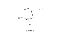
- the conventional lip channel steel was configured as described above, the following problems existed. That is, as apparent from the configuration of FIGS. 30 and 33, since the solar panel module is inclined, the horizontal base 2 is also inclined, but the horizontal base 2 itself is shown in FIGS. 30 and 31. As clearly shown in the configuration, since both lip shapes are used, the load resistance is strong and the deflection is small. However, the inclined platform 2 has both lip shapes. As shown in the figure, when it is inclined downward, rainwater 6 or the like that has entered from the outside accumulates inside the lower lip 2a, and its strength decreases due to rust, etc., and durability is a problem. It was.
- a single lip grooved steel according to the present invention is a longitudinally shaped grooved steel body having a grooved cross-sectional shape, and first and second side plates formed on both sides of a back plate of the grooved steel body, A lip formed at an end portion of the first side plate and projecting toward the second side plate side; and a flat portion formed at an end portion of the second side plate.
- the projecting width is a configuration equivalent to the second projecting width in which the lip projects from the first side plate.
- the horizontal pedestal comprising the single lip channel steel of Item 2 is disposed on the upper part of the vertical gantry perpendicular to the longitudinal direction of the vertical gantry, and a solar panel module having a plate shape is provided on the upper part of the horizontal gantry.
- the vertical base, the horizontal base and the solar panel module are provided horizontally or inclined, and the second side plate forms a right angle plate perpendicular to the plate direction of the back plate.
- the horizontal base made of the single lip channel steel according to Item 2 is configured to be provided on an inclined vertical base, and the second side plate is 90 degrees with respect to the plate direction of the back plate. 3.
- the horizontal stand according to claim 2 wherein the horizontal stand is extended toward the non-perpendicular direction via a wedge-shaped inclined member on the vertical stand that is horizontally arranged so that the second side plate is inclined downward.
- the second side plate is in the direction of the back plate.
- the vertical stand according to claim 2 extended in a non-perpendicular direction of 90 degrees or more is provided on the base member via a wedge-shaped inclined member, and the second side plate is the back plate.
- the horizontal stand according to claim 2 extended in a non-perpendicular direction of 90 degrees or more with respect to the plate direction of the first plate is provided on the vertical stand via an inclined member.
- the horizontal pedestal comprising the single lip channel steel according to Item 3 is disposed on the upper part of the vertical gantry perpendicular to the longitudinal direction of the vertical gantry, and a solar panel module having a plate shape is provided on the upper part of the horizontal gantry.
- the vertical base, the horizontal base and the solar panel module are provided horizontally or inclined, and the second side plate forms a right angle plate perpendicular to the plate direction of the back plate.
- the horizontal frame made of the single lip channel steel according to Item 3 is arranged on an inclined vertical frame.
- the second side plate is configured to be provided via a wedge-shaped inclined member on the vertically arranged vertical base so that the second side plate is inclined downward, and the second side plate is arranged with respect to the plate direction of the back plate.
- the vertical stand according to claim 3 wherein the vertical base is extended on a base member via a wedge-shaped inclined member, and the bent plate is a plate of the back plate.
- the horizontal stand according to claim 3 extended in a non-perpendicular direction of 90 degrees or more with respect to the direction is a configuration provided on the vertical stand via an inclined member, and the side plate
- the side plate width in the direction orthogonal to the longitudinal direction is the width of the back plate in the direction orthogonal to the longitudinal direction of the back plate.
- a configuration is a small Ri.
- the single lip channel steel according to the present invention is configured as described above, the following effects can be obtained. That is, a longitudinally shaped groove steel body having a groove shape in cross section, first and second side plates formed on both sides of a back plate of the groove steel body, and end portions of the first side plate And a lip that is formed and protrudes toward the second side plate, and a flat surface formed at the end of the second side plate, and the second side plate is perpendicular to the plate direction of the back plate. All of the water on the horizontal platform flows downward from the second side plate by forming a horizontal platform or a vertical platform and a non-right angle plate extending in a non-right angle direction of 90 degrees or more. Therefore, there is no rust and long durability can be obtained.
- the horizontal base made of the single lip channel steel according to claim 1 is disposed on the upper part of the vertical base perpendicular to the longitudinal direction of the vertical base, and the plate-like sunlight is formed on the upper part of the horizontal base.
- a panel module is provided, and the vertical base, the horizontal base, and the solar panel module can support the solar panel module for a long period of time by being horizontal or inclined.
- the second side plate extends in a non-right angle direction of 90 degrees or more with respect to the plate direction of the back plate.
- the horizontal base according to claim 1 provided on a member, wherein the second side plate extends in a non-perpendicular direction of 90 degrees or more with respect to the plate direction of the back plate.
- FIG. 5 is a perspective view of FIG. 4.
- FIG. 8 is a right side view of FIG. 7.
- It is a front view which shows the principal part of FIG. It is a perspective view which shows the principal part of FIG. It is a disassembled perspective view which shows the state which provides a vertical stand in a base member.
- FIG. 14 is a left side view of FIG. 13.
- FIG. 14 is a block diagram which shows the other form of the inclination mount frame using the half lip channel steel by this invention.
- FIG. 20 is a perspective view of FIG. 19. It is a front view which shows the other form of FIG.
- FIG. 1 It is a front view which shows the other form of FIG. It is a front view which shows the other form of FIG. It is a right view of FIG. It is a perspective view which shows the principal part of FIG. It is a disassembled perspective view which shows the state which provides a vertical stand in a base member. It is a disassembled perspective view which shows the state which provides a horizontal stand and a vertical stand in a base member. It is a block diagram which shows the assembly after FIG. It is a left view of FIG. It is a front view which shows the mount frame using the conventional both lip channel steel. It is an enlarged view which shows both the lip channel steel of FIG. It is a block diagram which shows the load resistance state of both lip channel steel of FIG. It is a perspective view which shows the mount frame of FIG.
- the present invention provides a single lip channel steel that is used as a horizontal frame or a vertical frame and that improves drainage of each frame when a flat solar panel module or the like is placed on the horizontal frame. With the goal.
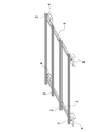
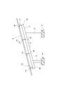
- FIG. 1 what is indicated by reference numeral 4 is a base member, and the vertical base 3 is supported on the base member 4 through a plurality of columns 5 in an inclined state.
- each vertical mount 3 On each vertical mount 3, a plurality of horizontal mounts 2 having a longitudinal direction B in a direction orthogonal to the longitudinal direction A of the vertical mount 3 are provided.
- a plate-shaped solar panel module 1 shown in FIG. 6 is fixed on each horizontal base 2 via attachment members such as an adhesive, bolts, and screws.
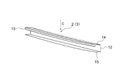
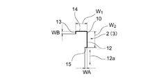
- the horizontal base 2 is made of a single lip grooved steel made of a groove steel body 10 having an overall U-shape.
- a first side plate 14 On both sides of the back plate 12, a first side plate 14 having a lip 13 and a right-angled right-angle plate 15 having only a flat plate-like portion not having the lip 13 are formed.
- the right-angle plate 15 extends in a right-angle direction from the plate direction 12a of the back plate 12 and does not have the lip 13. Therefore, the right-angle plate 15 is formed of only a flat plate and does not form a pool of water.
- the horizontal stand 2 has a moderate overall deflection state as indicated by a dotted line and a solid line. Yes, the horizontal base 2 has sufficient load resistance.
- the longitudinal direction A in FIG. 1 is an inclined direction in FIG. 1, the vertical frame 3 can be applied to both lip groove steels that are the same as the conventional configuration, but the vertical frame 3 of FIG. Single lip channel steel can be used.
- the vertical base 2 provided on the base member 4 is disposed in a horizontal state, and the vertical base 3 is orthogonal to the vertical base 3.
- a plurality of horizontal stands 2 are provided on the horizontal stand 2, and the solar panel module 1 is placed on the horizontal stand 2.
- the vertical base 3, the horizontal base 2, and the solar panel module 1 on each foundation member 4 are all arranged in a horizontal state, and the other structures are the same as those shown in FIGS. Then, the same code
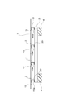
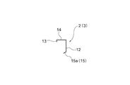
- the horizontal mount 2 and the vertical mount 3 described above are configured differently from the forms shown in FIGS. That is, in FIGS. 7 to 10, the horizontal base 2 is made of a single lip groove steel, and as shown in FIG. 9, the back plate 12, the first side plate 14 and the lip 13 are the same as those in FIG. However, the second side plate 15 extends in a non-right angle direction of 90 degrees or more with respect to the plate direction 12a of the back plate 12 and is a non-right angle plate 15a having only a flat portion inclined downward. It is configured.
- the horizontal frame 2 is horizontally disposed on the longitudinal vertical frame 3 provided horizontally on the base member 4, and the solar panel module 1 having a plate shape is formed on the horizontal frame 2.
- the vertical base 3 has the same structure as the horizontal base 2, and when the vertical base 3 is placed on the base member 4, a wedge-shaped tilt is provided between the non-right angle plate 15 a and the base member 4.
- the solar panel module 1, the horizontal base 2, and the vertical base are provided by interposing the member 20 and interposing the inclined member 20 between the vertical base 3 and the non-right angle plate 15 a of the horizontal base 2. 3 can be arranged horizontally with respect to the base member 4.
- the non-right angle plate 15a of each of the mounts 2 and 3 is inclined downward and extends, for example, as shown in FIG. 16, the non-right angle plate 15a is completely drained without collecting water, The durability of each of the pedestals 2 and 3 is remarkably improved.
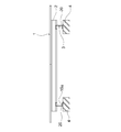
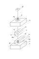
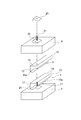
- each of the platforms 2 and 3 in the configuration in which each of the platforms 2 and 3 described in FIGS. 7 to 10 has a non-right angle plate as the second side plate 15a is as shown in FIGS. It is. That is, in FIG. 11, the inclined member 20 is provided on the anchor bolt 21 of the base member 4, and the vertical base 3 is mounted on the anchor bolt 21.
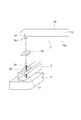
- FIG. 12 shows that the inclined member 20 is attached on the bolt 22 of the vertical base 3 provided on the base member 4 and is laminated on the anchor bolt 22 through the hole 2a of the horizontal base 2. ing. Therefore, with the above-described configuration, the vertical base 3 and the horizontal base 2 are arranged vertically and vertically.
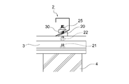
- FIGS. 13 and 14 show the structure after assembling the pedestals 2 and 3 of FIG. 12 described above.
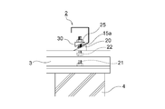
- FIG. 13 shows the horizontal pedestal 2 being fastened with nuts 25 in a horizontal state
- FIG. Indicates a vertical state.
- the inclined washer 30 and the nut 31 are used for the vertical mount 3 in FIG. 13, and the inclined washer 30 is used for the horizontal mount 2 in FIG. 14.
- FIGS. 15 to 29 shows another embodiment of the single lip channel steel according to the present invention.
- the same reference numerals are given to the same or equivalent parts as the configuration of the conventional example and the above-described FIG. 1 to FIG. 14, the description thereof is omitted, and the parts different from the above-described configurations of FIG. 1 to FIG.
- the projecting width of the second side plates 15 and 15a is made smaller than the configuration of FIG.
- what is indicated by reference numeral 4 is a base member, and the vertical base 3 is supported on the base member 4 through a plurality of columns 5 in an inclined state.
- each vertical mount 3 On each vertical mount 3, a plurality of horizontal mounts 2 having a longitudinal direction B in a direction orthogonal to the longitudinal direction A of the vertical mount 3 are provided.
- the plate-shaped solar panel module 1 shown in FIG. 6 is fixed via an attachment member such as an adhesive, a bolt, and a screw.
- the horizontal base 2 is made of a single-lip grooved steel made of a groove steel body 10 having an overall L-shape.
- a first side plate 14 having a lip 13 is provided on one side portion of the back plate 12, and a second side plate 15 made of a right-angle plate having only a flat plate portion is formed on the other side portion.
- the lip 13 and the second side plate 15 have the same protruding length and are shaped so that the lip protrudes from both. However, the second side plate 15 can be slightly longer.
- the second side plate 15 which is a right-angle plate, extends in a direction perpendicular to the plate direction 12 a of the back plate 12 and does not have the lip 13. Therefore, the second side plate 15 is formed of only a flat plate and does not form a pool of water. It is configured. As shown in FIG. 18, when the load test is performed by applying the force indicated by the arrow C, the horizontal platform 2 has a moderate overall deflection state as indicated by the dotted line and the solid line. Yes, the horizontal base 2 has sufficient load resistance. Further, since the longitudinal base 3 in FIG. 15 is inclined in the longitudinal direction A in FIG. 15, the same lip groove shape steel as that in the conventional structure can be applied, but the same structure as in the horizontal base 2 in FIG. Single lip channel steel can be used.
- the side plate width W 1 in the direction orthogonal to the longitudinal direction A of the side plate 14 is smaller than the back plate width W 2 in the direction orthogonal to the longitudinal direction A of the back plate 12, and is shown in FIG.
- the second side plate 15 is formed of a lip
- the plate widths W 1 and W 2 in the direction orthogonal to the longitudinal direction A of the side plate 14 and the back plate 12 are the same
- the lip 13 and the second side plate 15, the first side plate 14 and the back plate 12 constitute a single lip angle steel 40 as a single lip groove steel, and the action of drainage or the like is the same as that of the above-described embodiment of FIG.
- the first protruding width WA of the second side plates 15 and 15a from the back plate 12 is equal to the second protruding width WB of the lip 13 protruding from the first side plate 14.
- the vertical base 2 provided on the base member 4 is disposed in a horizontal state, and the vertical base 3 is orthogonal to the vertical base 3.
- a plurality of horizontal stands 2 are provided, and the solar panel module 1 shown in FIG. 6 is placed on the horizontal stand 2.
- the vertical base 3, the horizontal base 2, and the solar panel module 1 on each base member 4 are all arranged in a horizontal state, and the other structures are the same as those shown in FIGS. Then, the same code
- the horizontal mount 2 and the vertical mount 3 described above are configured differently from the forms shown in FIGS. That is, in FIG. 23 to FIG. 25, the horizontal base 2 is made of the single lip groove steel of another form of the single lip groove steel 2 and 3 shown in FIG. 16 and FIG. 22, the back plate 12, the side plate 14, and the lip 13 are the same as those in FIGS. 16 and 17, but the second side plate 15 is not 90 ° or more with respect to the plate direction 12 a of the back plate 12.
- the non-right-angle plate 15a is formed only in a plane portion that extends in a perpendicular direction and is inclined so as to descend downward.
- the horizontal frame 2 is horizontally disposed on the longitudinal vertical frame 3 provided horizontally on the base member 4, and the solar panel module 1 having a plate shape is formed on the horizontal frame 2.
- the vertical base 3 has the same structure as the horizontal base 2.
- the non-right angle plate 15 a that is the second side plate 15 and the base member 4 are arranged.
- a wedge-shaped inclined member 20 is interposed between the solar panel module 1 and the non-right angle plate 15a of the horizontal base 2 and the non-right-angle plate 15a of the horizontal base 2 to interpose the inclined member 20.
- the horizontal base 2 and the vertical base 3 can be disposed horizontally with respect to the base member 4.
- non-right angle plate 15a of each of the mounts 2 and 3 is inclined and extended downward, for example, water may accumulate in the non-right angle plate 15a of the above-described conventional configuration as shown in FIG. The water is completely drained, and the durability of the mounts 2 and 3 is remarkably improved.
- FIGS. 10 to 12 the assembly configuration of each of the platforms 2 and 3 in the configuration in which each of the platforms 2 and 3 described in FIGS. 10 to 12 has a non-right angle plate as the second side plate 15a is as shown in FIGS. It is. That is, in FIG. 26, the inclined member 20 is provided on the anchor bolt 21 of the base member 4, and the vertical base 3 is mounted on the anchor bolt 21.
- the inclined member 20 is mounted on the bolt 22 of the vertical base 3 provided on the base member 4 described above, and is stacked and attached on the anchor bolt 22 via the hole 2a of the horizontal base 2. ing. Therefore, with the above-described configuration, the vertical base 3 and the horizontal base 2 are arranged vertically and vertically.
- FIG. 28 and 29 show the structure after assembling each of the platforms 2 and 3 of FIG. 27 described above.
- FIG. 28 is tightened with the nut 25 in a state where the horizontal frame 2 is in the horizontal direction, and FIG. Indicates a vertical state.
- the inclined washer 30 and the nut 31 are used for the vertical mount 3 in FIG. 28, and the inclined washer 30 is used for the horizontal mount 2 in FIG.
- the single lip channel steel according to the present invention can be applied not only as a support for an object but also as an aggregate, a scaffold, or the like of a house.
Landscapes
- Engineering & Computer Science (AREA)
- Physics & Mathematics (AREA)
- Life Sciences & Earth Sciences (AREA)
- Sustainable Development (AREA)
- Sustainable Energy (AREA)
- Thermal Sciences (AREA)
- Chemical & Material Sciences (AREA)
- Combustion & Propulsion (AREA)
- Mechanical Engineering (AREA)
- General Engineering & Computer Science (AREA)
- Roof Covering Using Slabs Or Stiff Sheets (AREA)
- Panels For Use In Building Construction (AREA)
Abstract
Description
従って、例えば、前記横架台2上に位置する太陽光パネルモジュール1は、太陽光の光線方向に対してできるだけ直交する面となるように設けられている。
すなわち、図30及び図33の構成から明らかであるように、太陽光パネルモジュールは傾斜しているため、横架台2も傾斜しているが、この横架台2自体は、図30及び図31の構成から特に明らかであるように、両リップ形であるため、耐荷重は強く、たわみも小であるが、傾斜配置の横架台2は、両リップ形であるが故に、図30及び図31で示されるように、下方へ向けて傾斜している場合に、外部から入って来た雨水6等が下方のリップ2aの内側に溜まってしまい、錆等によってその強度が低下し、耐久性が問題となっていた。
すなわち、横断面形状が溝型をなす長手形状の溝形鋼本体と、前記溝形鋼本体の背板の両側部に形成された第1、第2側板と、前記第1側板の端部に形成され前記第2側板側に向けて突出するリップと、前記第2側板の端部に形成された平面部のみと、からなり、前記第2側板は、前記背板の板方向に対して直角方向の直角板又は90度以上の非直角方向に向けて延設された非直角板を有すると共に横架台又は縦架台を形成することにより、横架台にかかる水は全て第2側板から下方に流れて溜まらないため、錆の発生もなく、長い耐久性を得ることができる。
また、請求項1の片リップ溝形鋼からなる横架台は、縦架台の上部に、前記縦架台の長手方向と直交して配設され、前記横架台の上部には板状をなす太陽光パネルモジュールが設けられ、前記縦架台、横架台及び太陽光パネルモジュールは、水平又は傾斜していることにより、太陽光パネルモジュールを長期間にわたって支持し続けることができる。
また、前記第2側板が前記背板の板方向に対して直角方向の直角板を有する請求項1記載の片リップ溝形鋼からなる横架台は、傾斜配設された縦架台上に設けられていることにより、第2側板からの排水を完全に行うことができる。
また、前記第2側板が前記背板の板方向に対して90度以上の非直角方向に向けて延設されている請求項1記載の前記横架台は、前記第2側板が下り傾斜となるように水平配置の前記縦架台上にくさび型の傾斜部材を介して設けられていることにより、第2側板が下方へ向けて傾斜しているため、横架台及び縦架台共に完全な排水を行うことができる。
また、前記第2側板が前記背板の板方向に対して90度以上の非直角方向に向けて延設されている請求項1記載の前記縦架台は、くさび型の傾斜部材を介して基礎部材上に設けられ、前記第2側板が前記背板の板方向に対して90度以上の非直角方向に向けて延設されている請求項1記載の横架台が傾斜部材を介して前記縦架台上に設けられていることにより、各架台の各第2側板が非直角方向に傾斜していても、くさび状の各傾斜部材を用いることにより、横架台と縦架台を直角状に組合わせることができ、排水が完全な架台を得ることができる。
尚、従来例と同一又は同等部分には、同一符号を付し、の説明は省略する。
図1において符号4で示されるものは基礎部材であり、この基礎部材4上には複数の柱5を介して縦架台3が傾斜した状態で支持されている。
前記各横架台2上には、図6で示される板形状の太陽光パネルモジュール1が、接着剤、ボルト、ねじ等の取付部材を介して固定されている。
前記横架台2は、図2に拡大して示されているように、横架台2は全体形状がコ字形をなす溝形鋼本体10よりなる片リップ溝形鋼よりなり、この横架台2の背板12の両側には、リップ13を有する第1側板14と、このリップ13を有しない平板状の平面部のみの直角形状の直角板15とから構成されている。
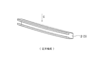
尚、前記横架台2は、図3にも示されるように、矢印Cで示される力を加えて荷重試験を行った場合、点線と実線で示されるように、全体のたわみ状態が中程度であり、横架台2としては十分な耐荷重性を有している。
さらに、前記縦架台3は、図1においてはその長手方向Aが傾斜方向であるため、従来構成と同じ両リップ溝形鋼でも適用可能であるが、前記横架台2と同じ構成の図2の片リップ溝形鋼を用いることができる。
すなわち、図7から図10において、前記横架台2は、片リップ溝形鋼よりなり、図9で示されるように、背板12及び第1側板14とリップ13は図1の構成と同一であるが、第2側板15が背板12の板方向12aに対して90度以上の非直角方向に延設されていると共に下方に向けて下るように傾斜した平面部のみの非直角板15aで構成されている。
前記縦架台3は前記横架台2と同一構造で構成されており、前記基礎部材4上に縦架台3を載置する場合は、前記非直角板15aと基礎部材4の間にくさび状の傾斜部材20を介装させ、前記縦架台3と横架台2の非直角板15aとの間にも、前記傾斜部材20を介装することにより、前記太陽光パネルモジュール1、横架台2及び縦架台3を基礎部材4に対して水平状態に配設することができる。
すなわち、図11においては、基礎部材4のアンカーボルト21に傾斜部材20を設け、このアンカーボルト21上に縦架台3を載置して取付けている。
従って、前述の構成により、縦架台3と横架台2は互いに直交配置でかつ上下配置されている。
尚、図13の縦架台3には傾斜型ワッシャ30とナット31を用い、図14では横架台2に対して傾斜型ワッシャ30を用いている。
尚、従来例及び前述の図1から図14の構成と同一又は同等部分には、同一符号を付し、その説明は省略すると共に、前述の図1から図14までの構成と異なる部分は、前記第2側板15、15aの突出幅を図2の構成よりも小としたことである。
図15において符号4で示されるものは基礎部材であり、この基礎部材4上には複数の柱5を介して縦架台3が傾斜した状態で支持されている。
前記各横架台2上には、前述の図6で示される板形状の太陽光パネルモジュール1が、接着剤、ボルト、ねじ等の取付部材を介して固定されている。
前記横架台2は、図16に拡大して示されているように、横架台2は全体形状がL字形をなす溝形鋼本体10よりなる片リップ溝形鋼よりなり、この横架台2の背板12の一側部には、リップ13を有する第1側板14が設けられ、その他側部には、平板状の平面部のみの直角板からなる第2側板15が形成されている。尚、このリップ13と第2側板15とは同じ突出長さで、両方にリップが出ているような形状とされているが、第2側板15の方をやや長くすることもできる。
尚、前記横架台2は、図18にも示されるように、矢印Cで示される力を加えて荷重試験を行った場合、点線と実線で示されるように、全体のたわみ状態が中程度であり、横架台2としては十分な耐荷重性を有している。
さらに、前記縦架台3は、図15においてはその長手方向Aが傾斜方向であるため、従来構成と同じ両リップ溝形鋼でも適用可能であるが、前記横架台2と同じ構成の図16の片リップ溝形鋼を用いることができる。
尚、前記側板14の長手方向Aと直交する方向の側板幅W1は、前記背板12の長手方向Aと直交する方向の背板幅W2より小であり、図17で示す図16の他の形態の場合、第2側板15はリップよりなり、前記側板14と背板12の長手方向Aと直交する方向の各板幅W1,W2は同一で、前記リップ13、第2側板15、第1側板14及び背板12により片リップ溝形鋼としての片リップ山形鋼40を構成し、排水等の作用は前述の図16の形態と同じである。
また、前記第2側板15、15aの背板12からの第1突出幅WAは、前記リップ13が第1側板14から突出している第2突出幅WBと同等である。
すなわち、図23から図25において、前記横架台2は、前述の図16及び図17で示される片リップ溝形鋼2,3の他の形態の片リップ溝形鋼よりなり、図21及び図22で示されるように、背板12及び側板14とリップ13は図16及び図17の構成と同一であるが、第2側板15が背板12の板方向12aに対して90度以上の非直角方向に延設されていると共に下方に向けて下るように傾斜した平面部のみの非直角板15aで構成されている。
前記縦架台3は前記横架台2と同一構造で構成されており、前記基礎部材4上に縦架台3を載置する場合は、前記第2側板15である非直角板15aと基礎部材4の間にくさび状の傾斜部材20を介装させ、前記縦架台3と横架台2の非直角板15aとの間にも、前記傾斜部材20を介装することにより、前記太陽光パネルモジュール1、横架台2及び縦架台3を基礎部材4に対して水平状態に配設することができる。
すなわち、図26においては、基礎部材4のアンカーボルト21に傾斜部材20を設け、このアンカーボルト21上に縦架台3を載置して取付けている。
従って、前述の構成により、縦架台3と横架台2は互いに直交配置でかつ上下配置されている。
尚、図28の縦架台3には傾斜型ワッシャ30とナット31を用い、図29では横架台2に対して傾斜型ワッシャ30を用いている。
Claims (12)
- 横断面形状が溝型をなす長手形状の溝形鋼本体(10)と、前記溝形鋼本体(10)の背板(12)の両側部に形成された第1、第2側板(14,15,15a)と、前記第1側板(14)の端部に形成され前記第2側板(15,15a)側に向けて突出するリップ(13)と、前記第2側板(15,15a)の端部に形成された平面部のみと、からなり、
前記第2側板(15,15a)は前記背板(12)の板方向(12a)に対して直角方向の直角板(15)又は90度以上の非直角方向に向けて延設された非直角板(15a)からなり、横架台(2)又は縦架台(3)を形成することを特徴とする片リップ溝形鋼。 - 前記第2側板(15,15a)の前記背板(12)からの第1突出幅(WA)は、前記リップ(13)が前記第1側板(14)から突出している第2突出幅(WB)より大であることを特徴とする請求項1記載の片リップ溝形鋼。
- 前記第2側板(15,15a)の前記背板(12)からの第1突出幅(WA)は、前記リップ(13)が前記第1側板(14)から突出している第2突出幅(WB)と同等であることを特徴とする請求項1記載の片リップ溝形鋼。
- 請求項2の片リップ溝形鋼からなる横架台(2)は、縦架台(3)の上部に、前記縦架台(3)の長手方向(A)と直交して配設され、前記横架台(2)の上部には板状をなす太陽光パネルモジュール(1)が設けられ、前記縦架台(3)、横架台(2)及び太陽光パネルモジュール(1)は、水平又は傾斜していることを特徴とする請求項2記載の片リップ溝形鋼。
- 前記第2側板(15)が前記背板(12)の板方向(12a)に対して直角方向の直角板(15)をなす請求項2記載の片リップ溝形鋼からなる横架台(2)は、傾斜配設された縦架台(3)上に設けられていることを特徴とする請求項2又は4記載の片リップ溝形鋼。
- 前記第2側板(15)が前記背板(12)の板方向(12a)に対して90度以上の非直角方向に向けて延設されている請求項2記載の前記横架台(2)は、前記第2側板(15)が下り傾斜となるように水平配置の前記縦架台(3)上にくさび型の傾斜部材(20)を介して設けられていることを特徴とする請求項2又は4記載の片リップ溝形鋼。
- 前記第2側板(15a)が前記背板(12)の板方向(12a)に対して90度以上の非直角方向に向けて延設されている請求項2記載の前記縦架台(3)は、くさび型の傾斜部材(20)を介して基礎部材(4)上に設けられ、前記第2側板(15a)が前記背板(12)の板方向(12a)に対して90度以上の非直角方向に向けて延設されている請求項2記載の横架台(2)が傾斜部材(20)を介して前記縦架台(3)上に設けられていることを特徴とする請求項2又は4記載の片リップ溝形鋼。
- 請求項3の片リップ溝形鋼からなる横架台(2)は、縦架台(3)の上部に、前記縦架台(3)の長手方向(A)と直交して配設され、前記横架台(2)の上部には板状をなす太陽光パネルモジュール(1)が設けられ、前記縦架台(3)、横架台(2)及び太陽光パネルモジュール(1)は、水平又は傾斜していることを特徴とする請求項3記載の片リップ溝形鋼。
- 前記第2側板(15)が前記背板(12)の板方向(12a)に対して直角方向の直角板(15)をなす請求項3記載の片リップ溝形鋼からなる横架台(2)は、傾斜配設された縦架台(3)上に設けられていることを特徴とする請求項3又は8記載の片リップ溝形鋼。
- 前記第2側板(15)が前記背板(12)の板方向(12a)に対して90度以上の非直角方向に向けて延設されている請求項3記載の前記横架台(2)は、前記第2側板(15)が下り傾斜となるように水平配置の前記縦架台(3)上にくさび型の傾斜部材(20)を介して設けられていることを特徴とする請求項3又は8記載の片リップ溝形鋼。
- 前記第2側板(15a)が前記背板(12)の板方向(12a)に対して90度以上の非直角方向に向けて延設されている請求項3記載の前記縦架台(3)は、くさび型の傾斜部材(20)を介して基礎部材(4)上に設けられ、前記第2側板(15a)が前記背板(12)の板方向(12a)に対して90度以上の非直角方向に向けて延設されている請求項3記載の横架台(2)が傾斜部材(20)を介して前記縦架台(3)上に設けられていることを特徴とする請求項3又は8記載の片リップ溝形鋼。
- 前記側板(14)の長手方向(A)と直交する方向の側板幅(W1)は、前記背板(12)の長手方向(A)と直交する方向の背板幅(W2)より小であることを特徴とする請求項3記載の片リップ溝形鋼。
Priority Applications (2)
| Application Number | Priority Date | Filing Date | Title |
|---|---|---|---|
| CN2011800654062A CN103328742A (zh) | 2011-02-23 | 2011-07-06 | 单唇缘槽钢 |
| US14/000,353 US20130326994A1 (en) | 2011-02-23 | 2011-07-06 | Steel single-lip channel bar |
Applications Claiming Priority (4)
| Application Number | Priority Date | Filing Date | Title |
|---|---|---|---|
| JP2011-037004 | 2011-02-23 | ||
| JP2011037004A JP2012172454A (ja) | 2011-02-23 | 2011-02-23 | 片リップ溝形鋼 |
| JP2011-037005 | 2011-02-23 | ||
| JP2011037005A JP5328056B2 (ja) | 2011-02-23 | 2011-02-23 | 太陽光パネルモジュールの架台 |
Publications (1)
| Publication Number | Publication Date |
|---|---|
| WO2012114550A1 true WO2012114550A1 (ja) | 2012-08-30 |
Family
ID=46720357
Family Applications (1)
| Application Number | Title | Priority Date | Filing Date |
|---|---|---|---|
| PCT/JP2011/065459 Ceased WO2012114550A1 (ja) | 2011-02-23 | 2011-07-06 | 片リップ溝形鋼 |
Country Status (2)
| Country | Link |
|---|---|
| CN (1) | CN103328742A (ja) |
| WO (1) | WO2012114550A1 (ja) |
Cited By (2)
| Publication number | Priority date | Publication date | Assignee | Title |
|---|---|---|---|---|
| DK181476B1 (en) * | 2022-06-07 | 2024-02-22 | Nordic Solar As | Mounting system for solar panel, solar panel comprising the system and method for mounting solar panel sheets on a solar panel |
| EP4211792A4 (en) * | 2020-09-14 | 2024-05-22 | Nextracker Inc. | SUPPORT FRAME FOR SUN FOLDER |
Citations (4)
| Publication number | Priority date | Publication date | Assignee | Title |
|---|---|---|---|---|
| JPH09177270A (ja) * | 1995-12-27 | 1997-07-08 | Sekisui Chem Co Ltd | 太陽電池モジュール及び該太陽電池モジュールの取付方法 |
| JPH09268701A (ja) * | 1996-04-02 | 1997-10-14 | Nippon Steel Corp | 部材耐力の優れた溝形鋼 |
| JP2004011282A (ja) * | 2002-06-07 | 2004-01-15 | Eishin:Kk | 太陽電池パネル取付け架台及びその組付け方法 |
| JP3159980U (ja) * | 2010-02-17 | 2010-06-10 | 松山鋼材株式会社 | 金属製支持ビーム |
Family Cites Families (2)
| Publication number | Priority date | Publication date | Assignee | Title |
|---|---|---|---|---|
| DE202006016709U1 (de) * | 2006-10-26 | 2007-02-08 | Essmann Gmbh | Lichtband |
| CN201671251U (zh) * | 2010-05-14 | 2010-12-15 | 山东雅百特金属结构系统有限公司 | 一种金属屋面太阳能板安装支架 |
-
2011
- 2011-07-06 CN CN2011800654062A patent/CN103328742A/zh active Pending
- 2011-07-06 WO PCT/JP2011/065459 patent/WO2012114550A1/ja not_active Ceased
Patent Citations (4)
| Publication number | Priority date | Publication date | Assignee | Title |
|---|---|---|---|---|
| JPH09177270A (ja) * | 1995-12-27 | 1997-07-08 | Sekisui Chem Co Ltd | 太陽電池モジュール及び該太陽電池モジュールの取付方法 |
| JPH09268701A (ja) * | 1996-04-02 | 1997-10-14 | Nippon Steel Corp | 部材耐力の優れた溝形鋼 |
| JP2004011282A (ja) * | 2002-06-07 | 2004-01-15 | Eishin:Kk | 太陽電池パネル取付け架台及びその組付け方法 |
| JP3159980U (ja) * | 2010-02-17 | 2010-06-10 | 松山鋼材株式会社 | 金属製支持ビーム |
Cited By (4)
| Publication number | Priority date | Publication date | Assignee | Title |
|---|---|---|---|---|
| EP4211792A4 (en) * | 2020-09-14 | 2024-05-22 | Nextracker Inc. | SUPPORT FRAME FOR SUN FOLDER |
| US12231082B2 (en) | 2020-09-14 | 2025-02-18 | Nextracker Llc | Support frames for solar trackers |
| DK181476B1 (en) * | 2022-06-07 | 2024-02-22 | Nordic Solar As | Mounting system for solar panel, solar panel comprising the system and method for mounting solar panel sheets on a solar panel |
| DK202200535A1 (en) * | 2022-06-07 | 2024-02-22 | Nordic Solar As | Solar Panel Mounting System and Method for Mounting Solar Pan el Plates to a Solar Panel |
Also Published As
| Publication number | Publication date |
|---|---|
| CN103328742A (zh) | 2013-09-25 |
Similar Documents
| Publication | Publication Date | Title |
|---|---|---|
| US9444396B2 (en) | Solar photovoltaic power generation panel mount | |
| JP5912098B2 (ja) | 太陽光発電パネル架台 | |
| EP3034961A1 (en) | Solar photovoltaic power generation panel mount | |
| JP2015078580A (ja) | 太陽光発電パネル架台 | |
| JP2014145186A (ja) | 屋根構造体 | |
| JP2004308402A (ja) | 簡易構造物 | |
| JP6087062B2 (ja) | 太陽電池アレイ | |
| JP6051027B2 (ja) | ソーラーパネル用架台 | |
| JP6441041B2 (ja) | 太陽電池パネル架台 | |
| CA2847200A1 (en) | Brace for deck railing | |
| JP6542161B2 (ja) | 太陽光発電パネル架台 | |
| JP5328056B2 (ja) | 太陽光パネルモジュールの架台 | |
| US20130326994A1 (en) | Steel single-lip channel bar | |
| JP6346755B2 (ja) | 太陽光発電パネル架台 | |
| JP3159980U (ja) | 金属製支持ビーム | |
| JP2012172454A (ja) | 片リップ溝形鋼 | |
| JP5886330B2 (ja) | 太陽光パネル架台 | |
| JP3159980U7 (ja) | ||
| KR20200137683A (ko) | 조경시설물 및 데크용 난간 | |
| KR101616229B1 (ko) | 조립식 난간 | |
| JP6215584B2 (ja) | 柵部材支持構造 | |
| JP5520745B2 (ja) | 締結具 | |
| JP6242728B2 (ja) | 太陽電池パネル架台 | |
| CN211337641U (zh) | 人防门顶部滑轨的安装结构 | |
| JP5788470B2 (ja) | 太陽電池モジュールの取付架台 |
Legal Events
| Date | Code | Title | Description |
|---|---|---|---|
| 121 | Ep: the epo has been informed by wipo that ep was designated in this application |
Ref document number: 11859350 Country of ref document: EP Kind code of ref document: A1 |
|
| DPE1 | Request for preliminary examination filed after expiration of 19th month from priority date (pct application filed from 20040101) | ||
| WWE | Wipo information: entry into national phase |
Ref document number: 14000353 Country of ref document: US |
|
| NENP | Non-entry into the national phase |
Ref country code: DE |
|
| WWE | Wipo information: entry into national phase |
Ref document number: 1301003806 Country of ref document: TH |
|
| 122 | Ep: pct application non-entry in european phase |
Ref document number: 11859350 Country of ref document: EP Kind code of ref document: A1 |