WO2012114534A1 - 溶銑傾注樋設備 - Google Patents
溶銑傾注樋設備 Download PDFInfo
- Publication number
- WO2012114534A1 WO2012114534A1 PCT/JP2011/055006 JP2011055006W WO2012114534A1 WO 2012114534 A1 WO2012114534 A1 WO 2012114534A1 JP 2011055006 W JP2011055006 W JP 2011055006W WO 2012114534 A1 WO2012114534 A1 WO 2012114534A1
- Authority
- WO
- WIPO (PCT)
- Prior art keywords
- tilting
- carriage
- hot metal
- moving
- wheels
- Prior art date
Links
Images


Classifications
-
- C—CHEMISTRY; METALLURGY
- C21—METALLURGY OF IRON
- C21C—PROCESSING OF PIG-IRON, e.g. REFINING, MANUFACTURE OF WROUGHT-IRON OR STEEL; TREATMENT IN MOLTEN STATE OF FERROUS ALLOYS
- C21C5/00—Manufacture of carbon-steel, e.g. plain mild steel, medium carbon steel or cast steel or stainless steel
- C21C5/28—Manufacture of steel in the converter
- C21C5/285—Plants therefor
-
- F—MECHANICAL ENGINEERING; LIGHTING; HEATING; WEAPONS; BLASTING
- F27—FURNACES; KILNS; OVENS; RETORTS
- F27D—DETAILS OR ACCESSORIES OF FURNACES, KILNS, OVENS, OR RETORTS, IN SO FAR AS THEY ARE OF KINDS OCCURRING IN MORE THAN ONE KIND OF FURNACE
- F27D3/00—Charging; Discharging; Manipulation of charge
- F27D3/14—Charging or discharging liquid or molten material
-
- C—CHEMISTRY; METALLURGY
- C21—METALLURGY OF IRON
- C21B—MANUFACTURE OF IRON OR STEEL
- C21B7/00—Blast furnaces
- C21B7/14—Discharging devices, e.g. for slag
-
- C—CHEMISTRY; METALLURGY
- C21—METALLURGY OF IRON
- C21C—PROCESSING OF PIG-IRON, e.g. REFINING, MANUFACTURE OF WROUGHT-IRON OR STEEL; TREATMENT IN MOLTEN STATE OF FERROUS ALLOYS
- C21C5/00—Manufacture of carbon-steel, e.g. plain mild steel, medium carbon steel or cast steel or stainless steel
- C21C5/52—Manufacture of steel in electric furnaces
- C21C5/5294—General arrangement or layout of the electric melt shop
-
- Y—GENERAL TAGGING OF NEW TECHNOLOGICAL DEVELOPMENTS; GENERAL TAGGING OF CROSS-SECTIONAL TECHNOLOGIES SPANNING OVER SEVERAL SECTIONS OF THE IPC; TECHNICAL SUBJECTS COVERED BY FORMER USPC CROSS-REFERENCE ART COLLECTIONS [XRACs] AND DIGESTS
- Y02—TECHNOLOGIES OR APPLICATIONS FOR MITIGATION OR ADAPTATION AGAINST CLIMATE CHANGE
- Y02P—CLIMATE CHANGE MITIGATION TECHNOLOGIES IN THE PRODUCTION OR PROCESSING OF GOODS
- Y02P10/00—Technologies related to metal processing
- Y02P10/20—Recycling
Definitions
- the present invention relates to a hot metal tilting runner equipment for injecting hot metal discharged from a blast furnace into a transportation vehicle, and is particularly suitable for facilitating replacement work of a tilting runner. It is a thing.
- the hot metal discharged from the blast furnace is poured out of the hot metal through the hot metal tip frame and poured into the tilting iron, and the tilting iron is tilted and injected into a transportation vehicle called a torpedo car. .
- a transportation vehicle called a torpedo car.
- the rail of the tilting trolley is extended in the longitudinal direction of the output, and the tilting rod is moved to the longitudinal direction of the output together with the trolley, and the tilting rod is lifted with a crane at a position where the hot metal frame is displaced. I made it.
- the present invention has been made paying attention to the problems as described above, and provides hot metal decanting equipment that can be removed without damaging the tilting iron without depending on the technique of the crane operator. It is for the purpose.
- the present invention provides a tilting iron for injecting hot metal discharged from a blast furnace into a transport vehicle, and two tap irons and a hot metal tip disposed opposite to each other above the tilting iron.
- a lower carriage provided with a small-sized rail and a wheel movable in a direction orthogonal to the longitudinal direction of the output, and the transportation of the wheel of the lower carriage in order to move in a direction orthogonal to the longitudinal direction of the output
- a hot metal tilting and pouring equipment provided with a long floor rail provided on a floor surface above a vehicle.
- the above-mentioned hot metal decanting equipment has an upper carriage moving motor for driving the wheels of the upper carriage mounted on the upper carriage, and a lower carriage moving motor for driving the wheels of the lower carriage. It is preferable to mount on the lower cart. Further, the above-mentioned hot metal decanting equipment has an upper carriage moving hydraulic cylinder for moving the upper carriage installed on the lower carriage, and the lower carriage moving hydraulic cylinder for moving the lower carriage is transported as described above. It is preferable to install on the floor above the vehicle.
- the wheel of the upper cart when adjusting the pouring position of the hot metal from the tap, the wheel of the upper cart is moved along the short rail of the lower cart.
- the position of the tilting anchor for each upper carriage is moved in the longitudinal direction of the output, and when the tilting anchor is removed, the position of the tilting anchor for each lower carriage is moved by moving the wheel of the lower carriage along the floor rail. Since it can move in the direction perpendicular to the longitudinal direction of the rod, this makes it possible to lift the tilting rod upward without interfering with the output, so that the tilting rod is not dependent on the skill of the crane operator. Can be removed without damage.
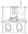
- FIG. 1 to 3 are general views of the hot metal tilting and pouring equipment of this embodiment, FIG. 1 is a front view, FIG. 2 is a side view, and FIG. 3 is a plan view.
- reference numeral 1 is a tilting anchor and reference numeral 2 is an output.
- a hot metal tip frame 3 is attached to the lower end of the tapping iron 2.
- the hot metal discharged from the illustrated blast furnace is poured from the hot metal 2 through the hot metal tip frame 3 to the tilting iron 1.
- the tilting rod 1 is supported by a support frame 4 and can be tilted in, for example, a clockwise direction or a counterclockwise direction in FIG.
- the hot metal can be poured into either of the two topped cars 6 by tilting the tilting rod 1 in the clockwise direction or the counterclockwise direction as shown in FIG.
- the two tapping rods 2 are arranged to face each other above the tilting rod 1 and, for example, the molten iron is alternately poured onto the tilting rod 1 from each tapping rod 2. Yes.
- the tilting rod 1 is removed, if it is lifted upward as it is, it will interfere with the hot metal tip frame 3 of the spout 2.
- an opening 21 through which the hot metal passes is formed in the upper floor 20 where the inclined pouring rod 1 is disposed above the topped car 6.
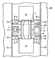
- the bearing 7 and the motor 5 that support the rotating shaft of the support frame 4 are mounted on the upper carriage 8.
- the upper carriage 8 is a vehicle body that is short in the tilting direction of the tilting rod 1, that is, in the direction perpendicular to the longitudinal direction of the output 2 and long in the longitudinal direction of the output 2 so that the molten iron is not applied when the tilting rod 1 is tilted. Is formed. Note that the central portion of the upper carriage 8 in the longitudinal direction of the vehicle body is slightly recessed so as not to inhibit the tilting rod 1 from tilting. Further, upper truck wheels 9 are rotatably attached to the four corners of the body of the upper truck 8. These upper cart wheels 9 are mounted on a short rail 11 laid on a lower cart 12 described later, and are movable in the longitudinal direction of the output 2. One of the four upper cart wheels 9 is rotationally driven by an upper cart moving motor 10 as an actuator.
- the upper carriage 8 is mounted on the short rail 11 on the lower carriage 12, and is movable in the laying direction of the short rail 11, that is, in the longitudinal direction of the output 2.
- the short rail is used. 11 may be short.
- the lower carriage 12 is also short in the tilting direction of the tilting rod 1, that is, in the direction perpendicular to the longitudinal direction of the barb 2, so that the molten iron is not applied when the tilting bar 1 is tilted. It is formed on a long car body.
- a part of the vehicle body of the lower carriage 12 is provided with a notch in accordance with the opening 21 of the upper floor 20.
- lower cart wheels 13 are rotatably attached to the four corners of the lower cart 12 body. These lower cart wheels 13 are mounted on a floor rail 15 laid on the upper floor 20 and are movable in a direction perpendicular to the longitudinal direction of the output 2. One of the four lower cart wheels 13 is rotationally driven by a lower cart moving motor 14 as an actuator. Therefore, the lower carriage 12 can move in the direction perpendicular to the longitudinal direction of the output 2 along the floor rail 15 together with the upper carriage 8 and the tilting rod 1, so when removing the tilting rod 1, for example, When the lower carriage 12 is moved to the position of the two-dot chain line in FIG. 2, no obstacles are left above the tilting rod 1, so that the tilting rod 1 can be lifted straight up with a crane or the like.
- the upper cart wheel 9 is moved along the short rail 11 of the lower cart 12.
- the position of the tilting rod 1 is moved in the longitudinal direction of the output 2 together with the upper cart 8, and when the tilting rod 1 is removed, the wheel of the lower cart is moved along the floor rail.
- the position of the rod 1 can be moved in a direction perpendicular to the longitudinal direction of the barb 2, and the tilted rod 1 can be lifted upward without interfering with the barb 2, so that the technique of the crane operator The decanting rod 1 can be removed without damaging it.
- an upper carriage moving motor 10 for driving the upper carriage wheel 9 of the upper carriage 8 is mounted on the upper carriage 8 and the lower carriage movement for driving the lower carriage wheel 13 of the lower carriage 12 is performed.
- the motor 14 By mounting the motor 14 on the lower carriage 12, the upper carriage 8 and the lower carriage 13 can be moved independently, and the position adjustment and removal of the tilting rod 1 are further facilitated.
- FIG. 4 shows another embodiment of the hot metal decanting equipment of the present invention.
- the hot metal decanting equipment shown in FIG. 4 is similar to the hot metal decanting equipment of the first embodiment, and the same components are denoted by the same reference numerals and detailed description thereof is omitted.
- the upper carriage moving motor for moving the upper carriage 8 and the lower carriage moving motor for moving the lower carriage 12 are removed, and instead the upper carriage moving hydraulic cylinder 22 and the lower carriage movement are removed.
- a hydraulic cylinder 23 is provided.
- the upper carriage moving hydraulic cylinder 22 has a cylinder tube attached to the lower carriage 12 and a piston rod connected to the upper carriage 8.
- the lower bogie moving hydraulic cylinder 23 has a cylinder tube attached to the upper floor and a piston rod connected to the lower bogie 12.
- the movement system using a hydraulic cylinder has a simpler configuration than the movement system using a motor. Therefore, in this embodiment, the movement system of the upper trolley 8 and the lower trolley 12 can be simplified.
- 1 tilting rod
- 2 is iron
- 3 is a hot metal frame
- 4 is a support frame
- 5 is a motor for moving the upper carriage
- 6 is a toped car
- 7 is a bearing
- 8 is an upper carriage
- 9 is for an upper carriage Wheels
- 10 is a motor for moving a lower carriage
- 11 is a short rail
- 12 is a lower carriage
- 13 is a wheel for a lower carriage
- 14 is a motor
- 15 is a rail on the floor
- 20 is an upper floor
- 21 is an opening
- 22 is an upper carriage Hydraulic cylinder for movement
- 23 is a hydraulic cylinder for lower cart movement
Abstract
Description
本発明は、上記のような問題点に着目してなされたものであり、クレーン作業者の技術に依存することなく、傾注樋を破損することなく取り外すことが可能な溶銑傾注樋設備を提供することを目的とするものである。
また、上記の溶銑傾注樋設備は、前記上部台車を移動するための上部台車移動用油圧シリンダを前記下部台車上に設置し、前記下部台車を移動するための下部台車移動用油圧シリンダを前記輸送車両上方の床面上に設置するのが好ましい。
また、上部台車を移動するための上部台車移動用油圧シリンダを下部台車上に設置し、下部台車を移動するための下部台車移動用油圧シリンダを輸送車両上方の床面上に設置したことにより、上部台車及び下部台車の移動システムが簡潔になる。
図1~図3は、本実施形態の溶銑傾注樋設備の全体図であり、図1は正面図、図2は側面図、図3は平面図である。図中の符号1は傾注樋、符号2は出銑樋である。出銑樋2の下端部には溶銑樋先金枠3が取付けられている。図示内高炉から出銑した溶銑は、出銑樋2から溶銑樋先金枠3を通って傾注樋1に注ぎ落とされる。傾注樋1は支持枠4に支持され、この支持枠4をモータ5で回転することにより、例えば図2の時計回り方向、反時計回り方向の何れにも傾動することができる。従って、図2のように傾注樋1を時計回り方向又は反時計回り方向に傾動することで、2台のトピードカー6の何れにも溶銑を注入することができる。なお、本実施形態では、2本の出銑樋2が、傾注樋1の上方で対向配設され、例えば夫々の出銑樋2から交互に溶銑を傾注樋1に注ぎ落とすように構成されている。その結果、傾注樋1を取り外す場合に、そのまま上方に持ち上げたのでは、出銑樋2の溶銑樋先金枠3と干渉してしまう。また、トピードカー6の上方で、且つ傾注樋1が配設されている上部床20には、溶銑が通過する開口部21が開設されている。
Claims (3)
- 高炉から出銑した溶銑を輸送車両に注入する傾注樋と、
前記傾注樋の上方で互いに対向配置された2本の出銑樋及び溶銑樋先金枠と、
前記傾注樋を傾動可能に支持し且つ前記出銑樋の長手方向に移動可能な車輪を備えた上部台車と、
前記上部台車の車輪が出銑樋の長手方向に移動するための短寸のレールを備え且つ前記出銑樋の長手方向と直交方向に移動可能な車輪を備えた下部台車と、
前記下部台車の車輪が出銑樋の長手方向と直交方向に移動するために前記輸送車両上方の床面に設けられた長寸の床上レールと、
を有する溶銑傾注樋設備。 - 前記上部台車の車輪を駆動するための上部台車移動用モータを当該上部台車上に搭載し、前記下部台車の車輪を駆動するための下部台車移動用モータを当該下部台車上に搭載したことを特徴とする請求項1に記載の溶銑傾注樋設備。
- 前記上部台車を移動するための上部台車移動用油圧シリンダを前記下部台車上に設置し、前記下部台車を移動するための下部台車移動用油圧シリンダを前記輸送車両上方の床面上に設置したことを特徴とする請求項1に記載の溶銑傾注樋設備。
Priority Applications (3)
| Application Number | Priority Date | Filing Date | Title |
|---|---|---|---|
| KR1020137022967A KR101445517B1 (ko) | 2011-02-25 | 2011-02-25 | 용선경주통 설비 |
| PCT/JP2011/055006 WO2012114534A1 (ja) | 2011-02-25 | 2011-02-25 | 溶銑傾注樋設備 |
| CN201180068352.5A CN103392011B (zh) | 2011-02-25 | 2011-02-25 | 铁水倾注沟设备 |
Applications Claiming Priority (1)
| Application Number | Priority Date | Filing Date | Title |
|---|---|---|---|
| PCT/JP2011/055006 WO2012114534A1 (ja) | 2011-02-25 | 2011-02-25 | 溶銑傾注樋設備 |
Publications (1)
| Publication Number | Publication Date |
|---|---|
| WO2012114534A1 true WO2012114534A1 (ja) | 2012-08-30 |
Family
ID=46720347
Family Applications (1)
| Application Number | Title | Priority Date | Filing Date |
|---|---|---|---|
| PCT/JP2011/055006 WO2012114534A1 (ja) | 2011-02-25 | 2011-02-25 | 溶銑傾注樋設備 |
Country Status (3)
| Country | Link |
|---|---|
| KR (1) | KR101445517B1 (ja) |
| CN (1) | CN103392011B (ja) |
| WO (1) | WO2012114534A1 (ja) |
Cited By (1)
| Publication number | Priority date | Publication date | Assignee | Title |
|---|---|---|---|---|
| KR101481620B1 (ko) * | 2013-09-06 | 2015-01-12 | 주식회사 포스코 | 용선 처리 장치 및 용선 처리 방법 |
Citations (3)
| Publication number | Priority date | Publication date | Assignee | Title |
|---|---|---|---|---|
| JPH0222354U (ja) * | 1988-07-28 | 1990-02-14 | ||
| JP2005097713A (ja) * | 2003-08-28 | 2005-04-14 | Jfe Steel Kk | 溶銑の脱珪方法 |
| JP2011068924A (ja) * | 2009-09-24 | 2011-04-07 | Jfe Steel Corp | 溶銑傾注樋構造 |
Family Cites Families (5)
| Publication number | Priority date | Publication date | Assignee | Title |
|---|---|---|---|---|
| JPS5292898A (en) * | 1976-01-30 | 1977-08-04 | Kawasaki Heavy Ind Ltd | Method and apparatus for treating molten slag |
| JPS62222009A (ja) * | 1986-03-22 | 1987-09-30 | Kawasaki Heavy Ind Ltd | サイホン式転炉出鋼口の炉体取付用芯出方法およびその装置 |
| DE3624266A1 (de) * | 1986-07-18 | 1988-01-21 | Gutehoffnungshuette Man | Vorrichtung zum auswechseln von hauptabstichrinnen an hochoefen |
| JP2003027117A (ja) * | 2001-07-16 | 2003-01-29 | Sumitomo Metal Ind Ltd | 溶融物傾注樋およびその交換方法 |
| KR20040046395A (ko) * | 2002-11-27 | 2004-06-05 | 주식회사 포스코 | 고로 용선을 운반하는 경주통의 이동장치 |
-
2011
- 2011-02-25 KR KR1020137022967A patent/KR101445517B1/ko active IP Right Grant
- 2011-02-25 CN CN201180068352.5A patent/CN103392011B/zh active Active
- 2011-02-25 WO PCT/JP2011/055006 patent/WO2012114534A1/ja active Application Filing
Patent Citations (3)
| Publication number | Priority date | Publication date | Assignee | Title |
|---|---|---|---|---|
| JPH0222354U (ja) * | 1988-07-28 | 1990-02-14 | ||
| JP2005097713A (ja) * | 2003-08-28 | 2005-04-14 | Jfe Steel Kk | 溶銑の脱珪方法 |
| JP2011068924A (ja) * | 2009-09-24 | 2011-04-07 | Jfe Steel Corp | 溶銑傾注樋構造 |
Cited By (1)
| Publication number | Priority date | Publication date | Assignee | Title |
|---|---|---|---|---|
| KR101481620B1 (ko) * | 2013-09-06 | 2015-01-12 | 주식회사 포스코 | 용선 처리 장치 및 용선 처리 방법 |
Also Published As
| Publication number | Publication date |
|---|---|
| KR20130122666A (ko) | 2013-11-07 |
| CN103392011A (zh) | 2013-11-13 |
| KR101445517B1 (ko) | 2014-09-29 |
| CN103392011B (zh) | 2015-08-05 |
Similar Documents
| Publication | Publication Date | Title |
|---|---|---|
| JP6444226B2 (ja) | 床版架設装置 | |
| KR100869057B1 (ko) | 교량 시공용 선회식 작업대차 | |
| JP4840496B2 (ja) | 溶銑傾注樋構造 | |
| JP5865156B2 (ja) | 橋桁の架設・撤去装置とこれを用いた橋桁の新設・撤去方法 | |
| JP4723469B2 (ja) | シールド掘進機後方の坑内作業設備 | |
| CN107130480B (zh) | 一种铁路道岔运输车 | |
| JP5815432B2 (ja) | 資材運搬装置及び資材運搬方法 | |
| WO2012114534A1 (ja) | 溶銑傾注樋設備 | |
| KR100588349B1 (ko) | 교량 시공용 무궤도 작업대차 | |
| KR200391266Y1 (ko) | 교량 시공용 무궤도 작업대차 | |
| CN111516429A (zh) | 一种轨道台车轮组更换工具 | |
| CN102770598B (zh) | 具有附加提升装置的夯实机 | |
| JP2011026069A (ja) | コンクリート製品の搬送敷設装置 | |
| CN208467676U (zh) | 一种可移动式汽车前后桥装配工装 | |
| JP2004263449A (ja) | Pc床版架設装置及び該装置を用いたpc床版架設方法 | |
| JP4669378B2 (ja) | 門形クレーンを搬送するための搬送台車 | |
| JP2012056557A (ja) | 軌陸作業車 | |
| JP5490814B2 (ja) | 圧延スタンドのロール用の駆動スピンドルを搬送するための台車および方法 | |
| JP2009242081A (ja) | レールマウント式門型クレーンの台車を用いたレーン移動方法及び装置 | |
| KR101147875B1 (ko) | 용광로용 서비스 장비 및 이를 이용하는 방법 | |
| JP2020122359A (ja) | 床版架設システム、床版の増設方法、及び、床版の減設方法 | |
| JP5739237B2 (ja) | 重量物の搬出方法及び搬入方法 | |
| JPH10184293A (ja) | トンネル工事で使用する搬送装置 | |
| CN113983822B (zh) | 烧结机头部安装方法及装置 | |
| CN203877402U (zh) | 一种钢坯提升输送机 |
Legal Events
| Date | Code | Title | Description |
|---|---|---|---|
| 121 | Ep: the epo has been informed by wipo that ep was designated in this application |
Ref document number: 11859109 Country of ref document: EP Kind code of ref document: A1 |
|
| NENP | Non-entry into the national phase |
Ref country code: DE |
|
| ENP | Entry into the national phase |
Ref document number: 20137022967 Country of ref document: KR Kind code of ref document: A |
|
| 122 | Ep: pct application non-entry in european phase |
Ref document number: 11859109 Country of ref document: EP Kind code of ref document: A1 |
|
| NENP | Non-entry into the national phase |
Ref country code: JP |