WO2012114472A1 - ハイブリッド車両の制御装置 - Google Patents
ハイブリッド車両の制御装置 Download PDFInfo
- Publication number
- WO2012114472A1 WO2012114472A1 PCT/JP2011/053967 JP2011053967W WO2012114472A1 WO 2012114472 A1 WO2012114472 A1 WO 2012114472A1 JP 2011053967 W JP2011053967 W JP 2011053967W WO 2012114472 A1 WO2012114472 A1 WO 2012114472A1
- Authority
- WO
- WIPO (PCT)
- Prior art keywords
- engine
- clutch
- torque
- transmission
- driver
- Prior art date
- Legal status (The legal status is an assumption and is not a legal conclusion. Google has not performed a legal analysis and makes no representation as to the accuracy of the status listed.)
- Ceased
Links
Images




Classifications
-
- B—PERFORMING OPERATIONS; TRANSPORTING
- B60—VEHICLES IN GENERAL
- B60W—CONJOINT CONTROL OF VEHICLE SUB-UNITS OF DIFFERENT TYPE OR DIFFERENT FUNCTION; CONTROL SYSTEMS SPECIALLY ADAPTED FOR HYBRID VEHICLES; ROAD VEHICLE DRIVE CONTROL SYSTEMS FOR PURPOSES NOT RELATED TO THE CONTROL OF A PARTICULAR SUB-UNIT
- B60W20/00—Control systems specially adapted for hybrid vehicles
- B60W20/10—Controlling the power contribution of each of the prime movers to meet required power demand
- B60W20/15—Control strategies specially adapted for achieving a particular effect
-
- B—PERFORMING OPERATIONS; TRANSPORTING
- B60—VEHICLES IN GENERAL
- B60K—ARRANGEMENT OR MOUNTING OF PROPULSION UNITS OR OF TRANSMISSIONS IN VEHICLES; ARRANGEMENT OR MOUNTING OF PLURAL DIVERSE PRIME-MOVERS IN VEHICLES; AUXILIARY DRIVES FOR VEHICLES; INSTRUMENTATION OR DASHBOARDS FOR VEHICLES; ARRANGEMENTS IN CONNECTION WITH COOLING, AIR INTAKE, GAS EXHAUST OR FUEL SUPPLY OF PROPULSION UNITS IN VEHICLES
- B60K6/00—Arrangement or mounting of plural diverse prime-movers for mutual or common propulsion, e.g. hybrid propulsion systems comprising electric motors and internal combustion engines
- B60K6/20—Arrangement or mounting of plural diverse prime-movers for mutual or common propulsion, e.g. hybrid propulsion systems comprising electric motors and internal combustion engines the prime-movers consisting of electric motors and internal combustion engines, e.g. HEVs
- B60K6/42—Arrangement or mounting of plural diverse prime-movers for mutual or common propulsion, e.g. hybrid propulsion systems comprising electric motors and internal combustion engines the prime-movers consisting of electric motors and internal combustion engines, e.g. HEVs characterised by the architecture of the hybrid electric vehicle
- B60K6/48—Parallel type
-
- B—PERFORMING OPERATIONS; TRANSPORTING
- B60—VEHICLES IN GENERAL
- B60L—PROPULSION OF ELECTRICALLY-PROPELLED VEHICLES; SUPPLYING ELECTRIC POWER FOR AUXILIARY EQUIPMENT OF ELECTRICALLY-PROPELLED VEHICLES; ELECTRODYNAMIC BRAKE SYSTEMS FOR VEHICLES IN GENERAL; MAGNETIC SUSPENSION OR LEVITATION FOR VEHICLES; MONITORING OPERATING VARIABLES OF ELECTRICALLY-PROPELLED VEHICLES; ELECTRIC SAFETY DEVICES FOR ELECTRICALLY-PROPELLED VEHICLES
- B60L15/00—Methods, circuits, or devices for controlling the traction-motor speed of electrically-propelled vehicles
- B60L15/20—Methods, circuits, or devices for controlling the traction-motor speed of electrically-propelled vehicles for control of the vehicle or its driving motor to achieve a desired performance, e.g. speed, torque, programmed variation of speed
-
- B—PERFORMING OPERATIONS; TRANSPORTING
- B60—VEHICLES IN GENERAL
- B60L—PROPULSION OF ELECTRICALLY-PROPELLED VEHICLES; SUPPLYING ELECTRIC POWER FOR AUXILIARY EQUIPMENT OF ELECTRICALLY-PROPELLED VEHICLES; ELECTRODYNAMIC BRAKE SYSTEMS FOR VEHICLES IN GENERAL; MAGNETIC SUSPENSION OR LEVITATION FOR VEHICLES; MONITORING OPERATING VARIABLES OF ELECTRICALLY-PROPELLED VEHICLES; ELECTRIC SAFETY DEVICES FOR ELECTRICALLY-PROPELLED VEHICLES
- B60L50/00—Electric propulsion with power supplied within the vehicle
- B60L50/10—Electric propulsion with power supplied within the vehicle using propulsion power supplied by engine-driven generators, e.g. generators driven by combustion engines
- B60L50/15—Electric propulsion with power supplied within the vehicle using propulsion power supplied by engine-driven generators, e.g. generators driven by combustion engines with additional electric power supply
-
- B—PERFORMING OPERATIONS; TRANSPORTING
- B60—VEHICLES IN GENERAL
- B60W—CONJOINT CONTROL OF VEHICLE SUB-UNITS OF DIFFERENT TYPE OR DIFFERENT FUNCTION; CONTROL SYSTEMS SPECIALLY ADAPTED FOR HYBRID VEHICLES; ROAD VEHICLE DRIVE CONTROL SYSTEMS FOR PURPOSES NOT RELATED TO THE CONTROL OF A PARTICULAR SUB-UNIT
- B60W10/00—Conjoint control of vehicle sub-units of different type or different function
- B60W10/02—Conjoint control of vehicle sub-units of different type or different function including control of driveline clutches
- B60W10/023—Fluid clutches
-
- B—PERFORMING OPERATIONS; TRANSPORTING
- B60—VEHICLES IN GENERAL
- B60W—CONJOINT CONTROL OF VEHICLE SUB-UNITS OF DIFFERENT TYPE OR DIFFERENT FUNCTION; CONTROL SYSTEMS SPECIALLY ADAPTED FOR HYBRID VEHICLES; ROAD VEHICLE DRIVE CONTROL SYSTEMS FOR PURPOSES NOT RELATED TO THE CONTROL OF A PARTICULAR SUB-UNIT
- B60W10/00—Conjoint control of vehicle sub-units of different type or different function
- B60W10/02—Conjoint control of vehicle sub-units of different type or different function including control of driveline clutches
- B60W10/024—Conjoint control of vehicle sub-units of different type or different function including control of driveline clutches including control of torque converters
- B60W10/026—Conjoint control of vehicle sub-units of different type or different function including control of driveline clutches including control of torque converters of lock-up clutches
-
- B—PERFORMING OPERATIONS; TRANSPORTING
- B60—VEHICLES IN GENERAL
- B60W—CONJOINT CONTROL OF VEHICLE SUB-UNITS OF DIFFERENT TYPE OR DIFFERENT FUNCTION; CONTROL SYSTEMS SPECIALLY ADAPTED FOR HYBRID VEHICLES; ROAD VEHICLE DRIVE CONTROL SYSTEMS FOR PURPOSES NOT RELATED TO THE CONTROL OF A PARTICULAR SUB-UNIT
- B60W10/00—Conjoint control of vehicle sub-units of different type or different function
- B60W10/04—Conjoint control of vehicle sub-units of different type or different function including control of propulsion units
- B60W10/06—Conjoint control of vehicle sub-units of different type or different function including control of propulsion units including control of combustion engines
-
- B—PERFORMING OPERATIONS; TRANSPORTING
- B60—VEHICLES IN GENERAL
- B60W—CONJOINT CONTROL OF VEHICLE SUB-UNITS OF DIFFERENT TYPE OR DIFFERENT FUNCTION; CONTROL SYSTEMS SPECIALLY ADAPTED FOR HYBRID VEHICLES; ROAD VEHICLE DRIVE CONTROL SYSTEMS FOR PURPOSES NOT RELATED TO THE CONTROL OF A PARTICULAR SUB-UNIT
- B60W10/00—Conjoint control of vehicle sub-units of different type or different function
- B60W10/10—Conjoint control of vehicle sub-units of different type or different function including control of change-speed gearings
-
- B—PERFORMING OPERATIONS; TRANSPORTING
- B60—VEHICLES IN GENERAL
- B60W—CONJOINT CONTROL OF VEHICLE SUB-UNITS OF DIFFERENT TYPE OR DIFFERENT FUNCTION; CONTROL SYSTEMS SPECIALLY ADAPTED FOR HYBRID VEHICLES; ROAD VEHICLE DRIVE CONTROL SYSTEMS FOR PURPOSES NOT RELATED TO THE CONTROL OF A PARTICULAR SUB-UNIT
- B60W20/00—Control systems specially adapted for hybrid vehicles
-
- B—PERFORMING OPERATIONS; TRANSPORTING
- B60—VEHICLES IN GENERAL
- B60W—CONJOINT CONTROL OF VEHICLE SUB-UNITS OF DIFFERENT TYPE OR DIFFERENT FUNCTION; CONTROL SYSTEMS SPECIALLY ADAPTED FOR HYBRID VEHICLES; ROAD VEHICLE DRIVE CONTROL SYSTEMS FOR PURPOSES NOT RELATED TO THE CONTROL OF A PARTICULAR SUB-UNIT
- B60W20/00—Control systems specially adapted for hybrid vehicles
- B60W20/40—Controlling the engagement or disengagement of prime movers, e.g. for transition between prime movers
-
- B—PERFORMING OPERATIONS; TRANSPORTING
- B60—VEHICLES IN GENERAL
- B60W—CONJOINT CONTROL OF VEHICLE SUB-UNITS OF DIFFERENT TYPE OR DIFFERENT FUNCTION; CONTROL SYSTEMS SPECIALLY ADAPTED FOR HYBRID VEHICLES; ROAD VEHICLE DRIVE CONTROL SYSTEMS FOR PURPOSES NOT RELATED TO THE CONTROL OF A PARTICULAR SUB-UNIT
- B60W30/00—Purposes of road vehicle drive control systems not related to the control of a particular sub-unit, e.g. of systems using conjoint control of vehicle sub-units
- B60W30/18—Propelling the vehicle
- B60W30/20—Reducing vibrations in the driveline
-
- B—PERFORMING OPERATIONS; TRANSPORTING
- B60—VEHICLES IN GENERAL
- B60K—ARRANGEMENT OR MOUNTING OF PROPULSION UNITS OR OF TRANSMISSIONS IN VEHICLES; ARRANGEMENT OR MOUNTING OF PLURAL DIVERSE PRIME-MOVERS IN VEHICLES; AUXILIARY DRIVES FOR VEHICLES; INSTRUMENTATION OR DASHBOARDS FOR VEHICLES; ARRANGEMENTS IN CONNECTION WITH COOLING, AIR INTAKE, GAS EXHAUST OR FUEL SUPPLY OF PROPULSION UNITS IN VEHICLES
- B60K6/00—Arrangement or mounting of plural diverse prime-movers for mutual or common propulsion, e.g. hybrid propulsion systems comprising electric motors and internal combustion engines
- B60K6/20—Arrangement or mounting of plural diverse prime-movers for mutual or common propulsion, e.g. hybrid propulsion systems comprising electric motors and internal combustion engines the prime-movers consisting of electric motors and internal combustion engines, e.g. HEVs
- B60K6/42—Arrangement or mounting of plural diverse prime-movers for mutual or common propulsion, e.g. hybrid propulsion systems comprising electric motors and internal combustion engines the prime-movers consisting of electric motors and internal combustion engines, e.g. HEVs characterised by the architecture of the hybrid electric vehicle
- B60K6/48—Parallel type
- B60K2006/4816—Electric machine connected or connectable to gearbox internal shaft
-
- B—PERFORMING OPERATIONS; TRANSPORTING
- B60—VEHICLES IN GENERAL
- B60L—PROPULSION OF ELECTRICALLY-PROPELLED VEHICLES; SUPPLYING ELECTRIC POWER FOR AUXILIARY EQUIPMENT OF ELECTRICALLY-PROPELLED VEHICLES; ELECTRODYNAMIC BRAKE SYSTEMS FOR VEHICLES IN GENERAL; MAGNETIC SUSPENSION OR LEVITATION FOR VEHICLES; MONITORING OPERATING VARIABLES OF ELECTRICALLY-PROPELLED VEHICLES; ELECTRIC SAFETY DEVICES FOR ELECTRICALLY-PROPELLED VEHICLES
- B60L2240/00—Control parameters of input or output; Target parameters
- B60L2240/10—Vehicle control parameters
- B60L2240/12—Speed
-
- B—PERFORMING OPERATIONS; TRANSPORTING
- B60—VEHICLES IN GENERAL
- B60L—PROPULSION OF ELECTRICALLY-PROPELLED VEHICLES; SUPPLYING ELECTRIC POWER FOR AUXILIARY EQUIPMENT OF ELECTRICALLY-PROPELLED VEHICLES; ELECTRODYNAMIC BRAKE SYSTEMS FOR VEHICLES IN GENERAL; MAGNETIC SUSPENSION OR LEVITATION FOR VEHICLES; MONITORING OPERATING VARIABLES OF ELECTRICALLY-PROPELLED VEHICLES; ELECTRIC SAFETY DEVICES FOR ELECTRICALLY-PROPELLED VEHICLES
- B60L2240/00—Control parameters of input or output; Target parameters
- B60L2240/40—Drive Train control parameters
- B60L2240/42—Drive Train control parameters related to electric machines
- B60L2240/421—Speed
-
- B—PERFORMING OPERATIONS; TRANSPORTING
- B60—VEHICLES IN GENERAL
- B60L—PROPULSION OF ELECTRICALLY-PROPELLED VEHICLES; SUPPLYING ELECTRIC POWER FOR AUXILIARY EQUIPMENT OF ELECTRICALLY-PROPELLED VEHICLES; ELECTRODYNAMIC BRAKE SYSTEMS FOR VEHICLES IN GENERAL; MAGNETIC SUSPENSION OR LEVITATION FOR VEHICLES; MONITORING OPERATING VARIABLES OF ELECTRICALLY-PROPELLED VEHICLES; ELECTRIC SAFETY DEVICES FOR ELECTRICALLY-PROPELLED VEHICLES
- B60L2240/00—Control parameters of input or output; Target parameters
- B60L2240/40—Drive Train control parameters
- B60L2240/44—Drive Train control parameters related to combustion engines
- B60L2240/441—Speed
-
- B—PERFORMING OPERATIONS; TRANSPORTING
- B60—VEHICLES IN GENERAL
- B60L—PROPULSION OF ELECTRICALLY-PROPELLED VEHICLES; SUPPLYING ELECTRIC POWER FOR AUXILIARY EQUIPMENT OF ELECTRICALLY-PROPELLED VEHICLES; ELECTRODYNAMIC BRAKE SYSTEMS FOR VEHICLES IN GENERAL; MAGNETIC SUSPENSION OR LEVITATION FOR VEHICLES; MONITORING OPERATING VARIABLES OF ELECTRICALLY-PROPELLED VEHICLES; ELECTRIC SAFETY DEVICES FOR ELECTRICALLY-PROPELLED VEHICLES
- B60L2240/00—Control parameters of input or output; Target parameters
- B60L2240/40—Drive Train control parameters
- B60L2240/50—Drive Train control parameters related to clutches
- B60L2240/507—Operating parameters
-
- B—PERFORMING OPERATIONS; TRANSPORTING
- B60—VEHICLES IN GENERAL
- B60L—PROPULSION OF ELECTRICALLY-PROPELLED VEHICLES; SUPPLYING ELECTRIC POWER FOR AUXILIARY EQUIPMENT OF ELECTRICALLY-PROPELLED VEHICLES; ELECTRODYNAMIC BRAKE SYSTEMS FOR VEHICLES IN GENERAL; MAGNETIC SUSPENSION OR LEVITATION FOR VEHICLES; MONITORING OPERATING VARIABLES OF ELECTRICALLY-PROPELLED VEHICLES; ELECTRIC SAFETY DEVICES FOR ELECTRICALLY-PROPELLED VEHICLES
- B60L2250/00—Driver interactions
- B60L2250/26—Driver interactions by pedal actuation
-
- B—PERFORMING OPERATIONS; TRANSPORTING
- B60—VEHICLES IN GENERAL
- B60L—PROPULSION OF ELECTRICALLY-PROPELLED VEHICLES; SUPPLYING ELECTRIC POWER FOR AUXILIARY EQUIPMENT OF ELECTRICALLY-PROPELLED VEHICLES; ELECTRODYNAMIC BRAKE SYSTEMS FOR VEHICLES IN GENERAL; MAGNETIC SUSPENSION OR LEVITATION FOR VEHICLES; MONITORING OPERATING VARIABLES OF ELECTRICALLY-PROPELLED VEHICLES; ELECTRIC SAFETY DEVICES FOR ELECTRICALLY-PROPELLED VEHICLES
- B60L2260/00—Operating Modes
- B60L2260/20—Drive modes; Transition between modes
- B60L2260/26—Transition between different drive modes
-
- B—PERFORMING OPERATIONS; TRANSPORTING
- B60—VEHICLES IN GENERAL
- B60L—PROPULSION OF ELECTRICALLY-PROPELLED VEHICLES; SUPPLYING ELECTRIC POWER FOR AUXILIARY EQUIPMENT OF ELECTRICALLY-PROPELLED VEHICLES; ELECTRODYNAMIC BRAKE SYSTEMS FOR VEHICLES IN GENERAL; MAGNETIC SUSPENSION OR LEVITATION FOR VEHICLES; MONITORING OPERATING VARIABLES OF ELECTRICALLY-PROPELLED VEHICLES; ELECTRIC SAFETY DEVICES FOR ELECTRICALLY-PROPELLED VEHICLES
- B60L2270/00—Problem solutions or means not otherwise provided for
- B60L2270/10—Emission reduction
- B60L2270/14—Emission reduction of noise
- B60L2270/145—Structure borne vibrations
-
- B—PERFORMING OPERATIONS; TRANSPORTING
- B60—VEHICLES IN GENERAL
- B60W—CONJOINT CONTROL OF VEHICLE SUB-UNITS OF DIFFERENT TYPE OR DIFFERENT FUNCTION; CONTROL SYSTEMS SPECIALLY ADAPTED FOR HYBRID VEHICLES; ROAD VEHICLE DRIVE CONTROL SYSTEMS FOR PURPOSES NOT RELATED TO THE CONTROL OF A PARTICULAR SUB-UNIT
- B60W2510/00—Input parameters relating to a particular sub-units
- B60W2510/02—Clutches
- B60W2510/0208—Clutch engagement state, e.g. engaged or disengaged
- B60W2510/0233—Clutch engagement state, e.g. engaged or disengaged of torque converter lock-up clutch
-
- B—PERFORMING OPERATIONS; TRANSPORTING
- B60—VEHICLES IN GENERAL
- B60W—CONJOINT CONTROL OF VEHICLE SUB-UNITS OF DIFFERENT TYPE OR DIFFERENT FUNCTION; CONTROL SYSTEMS SPECIALLY ADAPTED FOR HYBRID VEHICLES; ROAD VEHICLE DRIVE CONTROL SYSTEMS FOR PURPOSES NOT RELATED TO THE CONTROL OF A PARTICULAR SUB-UNIT
- B60W2510/00—Input parameters relating to a particular sub-units
- B60W2510/02—Clutches
- B60W2510/0241—Clutch slip, i.e. difference between input and output speeds
-
- Y—GENERAL TAGGING OF NEW TECHNOLOGICAL DEVELOPMENTS; GENERAL TAGGING OF CROSS-SECTIONAL TECHNOLOGIES SPANNING OVER SEVERAL SECTIONS OF THE IPC; TECHNICAL SUBJECTS COVERED BY FORMER USPC CROSS-REFERENCE ART COLLECTIONS [XRACs] AND DIGESTS
- Y02—TECHNOLOGIES OR APPLICATIONS FOR MITIGATION OR ADAPTATION AGAINST CLIMATE CHANGE
- Y02T—CLIMATE CHANGE MITIGATION TECHNOLOGIES RELATED TO TRANSPORTATION
- Y02T10/00—Road transport of goods or passengers
- Y02T10/10—Internal combustion engine [ICE] based vehicles
- Y02T10/40—Engine management systems
-
- Y—GENERAL TAGGING OF NEW TECHNOLOGICAL DEVELOPMENTS; GENERAL TAGGING OF CROSS-SECTIONAL TECHNOLOGIES SPANNING OVER SEVERAL SECTIONS OF THE IPC; TECHNICAL SUBJECTS COVERED BY FORMER USPC CROSS-REFERENCE ART COLLECTIONS [XRACs] AND DIGESTS
- Y02—TECHNOLOGIES OR APPLICATIONS FOR MITIGATION OR ADAPTATION AGAINST CLIMATE CHANGE
- Y02T—CLIMATE CHANGE MITIGATION TECHNOLOGIES RELATED TO TRANSPORTATION
- Y02T10/00—Road transport of goods or passengers
- Y02T10/60—Other road transportation technologies with climate change mitigation effect
- Y02T10/62—Hybrid vehicles
-
- Y—GENERAL TAGGING OF NEW TECHNOLOGICAL DEVELOPMENTS; GENERAL TAGGING OF CROSS-SECTIONAL TECHNOLOGIES SPANNING OVER SEVERAL SECTIONS OF THE IPC; TECHNICAL SUBJECTS COVERED BY FORMER USPC CROSS-REFERENCE ART COLLECTIONS [XRACs] AND DIGESTS
- Y02—TECHNOLOGIES OR APPLICATIONS FOR MITIGATION OR ADAPTATION AGAINST CLIMATE CHANGE
- Y02T—CLIMATE CHANGE MITIGATION TECHNOLOGIES RELATED TO TRANSPORTATION
- Y02T10/00—Road transport of goods or passengers
- Y02T10/60—Other road transportation technologies with climate change mitigation effect
- Y02T10/64—Electric machine technologies in electromobility
-
- Y—GENERAL TAGGING OF NEW TECHNOLOGICAL DEVELOPMENTS; GENERAL TAGGING OF CROSS-SECTIONAL TECHNOLOGIES SPANNING OVER SEVERAL SECTIONS OF THE IPC; TECHNICAL SUBJECTS COVERED BY FORMER USPC CROSS-REFERENCE ART COLLECTIONS [XRACs] AND DIGESTS
- Y02—TECHNOLOGIES OR APPLICATIONS FOR MITIGATION OR ADAPTATION AGAINST CLIMATE CHANGE
- Y02T—CLIMATE CHANGE MITIGATION TECHNOLOGIES RELATED TO TRANSPORTATION
- Y02T10/00—Road transport of goods or passengers
- Y02T10/60—Other road transportation technologies with climate change mitigation effect
- Y02T10/7072—Electromobility specific charging systems or methods for batteries, ultracapacitors, supercapacitors or double-layer capacitors
-
- Y—GENERAL TAGGING OF NEW TECHNOLOGICAL DEVELOPMENTS; GENERAL TAGGING OF CROSS-SECTIONAL TECHNOLOGIES SPANNING OVER SEVERAL SECTIONS OF THE IPC; TECHNICAL SUBJECTS COVERED BY FORMER USPC CROSS-REFERENCE ART COLLECTIONS [XRACs] AND DIGESTS
- Y02—TECHNOLOGIES OR APPLICATIONS FOR MITIGATION OR ADAPTATION AGAINST CLIMATE CHANGE
- Y02T—CLIMATE CHANGE MITIGATION TECHNOLOGIES RELATED TO TRANSPORTATION
- Y02T10/00—Road transport of goods or passengers
- Y02T10/60—Other road transportation technologies with climate change mitigation effect
- Y02T10/72—Electric energy management in electromobility
-
- Y—GENERAL TAGGING OF NEW TECHNOLOGICAL DEVELOPMENTS; GENERAL TAGGING OF CROSS-SECTIONAL TECHNOLOGIES SPANNING OVER SEVERAL SECTIONS OF THE IPC; TECHNICAL SUBJECTS COVERED BY FORMER USPC CROSS-REFERENCE ART COLLECTIONS [XRACs] AND DIGESTS
- Y10—TECHNICAL SUBJECTS COVERED BY FORMER USPC
- Y10S—TECHNICAL SUBJECTS COVERED BY FORMER USPC CROSS-REFERENCE ART COLLECTIONS [XRACs] AND DIGESTS
- Y10S903/00—Hybrid electric vehicles, HEVS
- Y10S903/902—Prime movers comprising electrical and internal combustion motors
Definitions
- the present invention relates to a control device for a hybrid vehicle, and more particularly to a shock reduction at the time of engine start.
- Patent Document 1 An engine, an electric motor, a clutch provided in a power transmission path between the engine and the electric motor, and a fluid transmission device having a lock-up clutch provided between the electric motor and a drive wheel Hybrid vehicles are known.
- the parallel hybrid power train 1 (power transmission device) of Patent Document 1 is an example.
- Patent Document 1 describes that when an engine is started from running of a motor by an electric motor, a shock due to torque fluctuation generated when the engine is started is suppressed by slip operation of a lock-up clutch.
- the slip rotation speed of the lockup clutch at the time of engine start is set based on the characteristics of the torque converter. Then, the target rotational speed of the electric motor is determined from the turbine rotational speed of the torque converter and the slip rotational speed.
- the power train 1 configured as described above cannot cope with shock reduction according to whether or not the accelerator pedal is depressed. For example, when the remaining amount of the battery decreases, the engine is started even when the accelerator pedal is not depressed. In such a case, since the engine start is not intended by the driver, the sensitivity of the shock to the driver's engine start increases. However, in the powertrain 1, the slip rotation speed is set according to the characteristics of the torque converter regardless of whether or not the accelerator pedal is depressed, so that the driver may feel a shock.
- the present invention has been made against the background of the above circumstances.
- the object of the present invention is to reduce the shock given to the driver when starting the engine from the motor running by the electric motor in the hybrid vehicle.
- An object of the present invention is to provide a control device for a hybrid vehicle.
- the gist of the invention according to claim 1 is: (a) an engine, an electric motor, a clutch provided in a power transmission path between the engine and the electric motor, A control device for a hybrid vehicle comprising a fluid transmission device having a lock-up clutch provided in a power transmission path between the electric motor and driving wheels, wherein (b) the engine is driven from motor running by the electric motor.
- the clutch is engaged and the slip control of the lock-up clutch is executed.
- C When the engine is started by the request of the hybrid system, the driver The engagement pressure of the lock-up clutch is made lower than in the case of engine start due to the acceleration request.
- the engagement pressure of the lock-up clutch is lowered compared with the case of engine start at the driver's acceleration request.
- the sensitivity of the user to the shock is high and the engagement pressure of the lockup clutch is reduced when the engine is started due to the demand of the hybrid system to reduce the torque transmission rate by the lockup clutch, while the torque via the fluid of the fluid transmission device
- a transmission is further provided between the fluid transmission device and the drive wheel.
- the transmission gear ratio exceeds a predetermined value
- the transmission does not exceed the predetermined value.
- the engagement pressure of the lockup clutch is lowered.
- the gear ratio of the transmission exceeds a predetermined value
- the torque fluctuation is largely transmitted to the output side.
- the engagement pressure of the lockup clutch reduces the engagement pressure of the lockup clutch, the torque fluctuation is effectively absorbed by the fluid transmission device, so that the shock is reduced.
- the engine start according to the request of the hybrid system corresponds to the case of starting the engine for power generation or the case of starting the engine for applying engine braking.
- the engine start due to the demand of the hybrid system is an engine start that is not intended by the driver, and the sensitivity of the driver to a shock at the time of engine start increases.
- torque fluctuation at engine start is effective due to fluid slippage during torque transmission It can be absorbed and can reduce shock.
- the engine start by the driver's acceleration request corresponds to the engine start when the accelerator pedal is depressed by the driver.
- the driver's acceleration demand increases, while the sensitivity to shock decreases.
- the engagement pressure of the lockup clutch becomes higher than the engagement pressure set at the start of the hybrid system, so that the efficiency of the fluid transmission device is improved and the uncomfortable feeling due to insufficient driving force is reduced. Can do.
- FIG. 2 is a flowchart for explaining a main part of a control operation of the electronic control device of FIG.
- the torque required for starting the engine is added to the torque required for running the motor and output from the electric motor. If it does in this way, deficiency of the driving force at the time of motor running can be controlled.
- FIG. 1 is a diagram conceptually showing the structure of a drive system of a hybrid vehicle 10 according to an embodiment of the present invention.
- the hybrid vehicle 10 includes an electric motor 12 and an engine 14 that is started by the electric motor 12.
- the power from the electric motor 12 and the engine 14 is transmitted to the left and right via a torque converter 16 having a lock-up clutch LU, an automatic transmission 18, a propeller shaft 19 (output shaft), a differential gear device 20, and a pair of left and right axles 22, respectively. It is transmitted to the pair of drive wheels 24.
- the hybrid vehicle 10 is driven by one, the other, and both of the electric motor 12 and the engine 14. That is, the hybrid vehicle 10 is in any one of the traveling states of motor traveling (EV traveling) using only the electric motor 12, engine traveling using only the engine 14, and hybrid traveling using the electric motor 12 and the engine 14.
- EV traveling motor traveling
- the engine 14 is configured by a direct injection gasoline engine or a diesel engine in which fuel is directly injected into the combustion chamber, and an output member of the engine 14, that is, a crankshaft 26 is connected to the rotor 30 of the electric motor 12 via the clutch K0.
- the rotor 30 of the electric motor 12 is connected to the input member of the torque converter 16, that is, the front cover 32.
- the clutch K0 is a hydraulic friction engagement device, and interrupts the power transmission path between the clutch shaft 26 and the front cover 32 according to the hydraulic pressure supplied from the hydraulic control circuit 34.
- the automatic transmission 18 is composed of, for example, a stepped transmission capable of shifting to a plurality of shift stages, and is shifted based on a shift diagram (not shown) composed of a vehicle speed V and an accelerator opening Acc, for example.
- FIG. 2 is a cross-sectional view showing the electric motor 12, the torque converter 16, the automatic transmission 18 and the crankshaft 26, which are partially cut away, in FIG.
- the electric motor 12, the torque converter 16, the automatic transmission 18, and the crankshaft 26 are configured substantially symmetrically with respect to their common axis C, and the lower half of the axis C is omitted in FIG. ing.
- the transmission case 36 is a split type case made of, for example, aluminum die casting, and is fixed to a vehicle body or the like.
- the clutch K0 includes a bottomed cylindrical clutch drum 38, a cylindrical clutch hub 40 having a diameter smaller than that of the clutch drum 38 and concentrically with the clutch drum 38 and capable of relative rotation, and the clutch drum 38 A friction engagement member 42 provided in an annular gap between the clutch hub 40 and a clutch piston 44 that presses the friction engagement member 42 in the axial direction is provided.
- the torque converter 16 is a non-rotating member through a pump impeller 16p connected to the engine 14 and the electric motor 12, a turbine impeller 16t connected to the input shaft 18a of the automatic transmission 18, and a one-way clutch.
- a stator impeller 16s connected to the transmission case 36, and power is transmitted through the fluid.
- ⁇ P differential pressure
- the engagement pressure ⁇ P it is controlled to any one of an open state, a complete engagement state, and a slip engagement state. For example, when the oil pressure Pin of the engagement side oil chamber 16a is equal to the oil pressure Pout of the release side oil chamber 16b, the engagement pressure ⁇ P becomes zero and the lockup clutch LU is released. Further, when the engagement pressure ⁇ P becomes a positive value, the lockup clutch LU is slip-engaged according to the magnitude.
- the slip rotational speed Nslip decreases as the engagement pressure ⁇ P increases. Further, when the engagement pressure ⁇ P reaches the maximum value, the lockup clutch LU is completely engaged, and the front cover 32 and the input shaft 18a of the automatic transmission 18 are directly connected.
- Np indicates the pump rotation speed Np of the pump impeller 16p, and in this embodiment, it is equal to the motor rotation speed Nmg of the motor 12.
- Nt represents the turbine rotational speed Nt of the turbine impeller 16t.
- the clutch drum 38 is integrally fixed to a boss portion 30a described later of the rotor 30 of the electric motor 12 by welding or the like, and is provided so as to be rotatable together with the rotor 30.
- the frictional engagement member 42 is provided between a plurality of annular plate-like separators engaged with the clutch drum 38 so as not to rotate relative to each other, and is engaged with the clutch hub 40 so as not to rotate relative to each other. And a plurality of annular plate-like friction plates.
- the crankshaft 26 is connected at its output end, that is, one end on the side of the motor 12, to a rotary shaft 48 connected to the clutch hub 40 of the clutch K0 via drive plates 46 and 47, respectively.
- the crankshaft 26 and the clutch hub 40 are connected to each other via drive plates 46 and 47 and a rotary shaft 48 so as to be rotatable.
- the electric motor 12 includes a rotor 30 that is rotatably supported around the axis C by a transmission case 36 on the outer peripheral side of the rotating shaft 48, and a stator 50 that is integrally fixed to the transmission case 36 on the outer peripheral side of the rotor 30. It has.
- the rotor 30 is in a state in which a slight gap is provided between the cylindrical boss portion 30a rotatably supported by the transmission case 36 via a pair of bearings 52 and the stator 50 on the inner peripheral side of the stator 50. And a rotor portion 30b having a plurality of disk-shaped steel plates laminated in the axial direction, and a connecting portion 30c for integrally connecting the boss portion 30a and the rotor portion 30b.
- the rotor 30 is coupled to the front cover 32 via a transmission member 54 that is coupled to the inner peripheral side of the rotor portion 30b and is integrally fixed to the front cover 32 by, for example, welding.
- the stator 50 is annularly wound around a core 50a in which a plurality of disk-shaped steel plates are respectively laminated in the axial direction, and a part of the inner peripheral portion of the core 50a in the circumferential direction. And a provided coil 50b.
- the stator 50 is integrally fixed to the transmission case 36 by a plurality of bolts 53 at a plurality of locations in the circumferential direction.
- the electric motor 12 configured as described above is connected to a power storage device 57 such as a battery or a capacitor via the inverter 56 of FIG. 1, and the inverter 56 is controlled to adjust the drive current supplied to the coil 50b.
- a power storage device 57 such as a battery or a capacitor
- the inverter 56 is controlled to adjust the drive current supplied to the coil 50b.
- the output torque from the electric motor 12 can be increased or decreased.
- the output torque from the electric motor 12 is output only to the torque converter 16 when the clutch K0 is not engaged, but when the clutch K0 is engaged, a part of the output torque is output to the torque converter 16 and the other part is It is output to the engine 14.
- FIG. 1 is also a block diagram illustrating a control system of the hybrid vehicle 10.
- the electronic control unit 58 includes a so-called microcomputer having a CPU, a RAM, a ROM, an input / output interface, and the like.
- the electronic control unit 58 performs signal processing according to a program stored in advance in the ROM while the CPU uses the temporary storage function of the RAM, thereby controlling the output of the engine 14, the start control of the engine 14, and the automatic transmission 18. Shift control, engagement force control of the clutch K0, and the like are executed.
- the electronic control device 58 functions as a vehicle engine start control device.
- the seed input signal detected by each sensor provided in the hybrid vehicle 10 is supplied to the electronic control unit 58.
- the input signal for example, a signal indicating the accelerator opening degree Acc [%] which is the depression amount of the accelerator pedal 61 detected by the accelerator opening sensor 60, the motor rotation speed Nmg [detected by the motor rotation speed sensor 62].
- rpm a signal representing the engine rotational speed Ne [rpm] detected by the engine rotational speed sensor 64, a signal representing the turbine rotational speed Nt [rpm] detected by the turbine rotational speed sensor 66, and a vehicle speed sensor 68.
- V vehicle speed V [km / h] corresponding to the detected rotational speed Nout of the propeller shaft 19 (output shaft) of the automatic transmission 18.
- output signals are supplied from the electronic control device 58 to each device provided in the hybrid vehicle 10.
- Examples of the output signal include a signal supplied to the inverter 56 for output control of the electric motor 12, a signal supplied to the hydraulic control circuit 34 for controlling the engagement force of the clutch K0, the lockup clutch LU, and the like. is there.
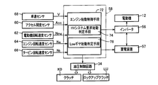
- FIG. 3 is a functional block diagram for explaining the main part of the control function according to the present invention provided in the electronic control unit 58.
- the engine start control means 72 executes engine start control when receiving a command to start the engine 14 from motor travel (EV travel) by the electric motor 12. Specifically, the engine start control means 72 engages the clutch K0 to start the engine 14 from the motor running state, that is, the clutch K0 is released and the lockup clutch LU is engaged. Then, control for slip-engaging the lock-up clutch LU is started. Further, the engine start control means 72 outputs a compensation torque required for starting the engine in addition to the torque due to the motor running. The compensation torque is set to a value set in advance according to the torque capacity of the clutch K0 from the start of the engine start control. By outputting this compensation torque, it is possible to prevent a decrease in torque output to the drive wheel 24 when the engine is started.
- HV system request start determination means 74 determines whether the start of the engine 14 is due to a request of the hybrid system.
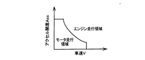
- a specific engine start according to the request of the hybrid system for example, a case where the charge capacity SOC of the power storage device 57 falls below a preset lower limit value and the engine is started for power generation is applicable. In such a case, it is necessary to start the engine 14 even if the traveling state of the vehicle is within the motor traveling region shown in FIG.
- the charge capacity SOC of the power storage device 57 exceeds a preset upper limit value, and braking by rotation of the engine 12 is performed instead of braking by the electric motor 12, that is, engine braking
- the independent operation by the engine 12 is not executed, but the engine 12 is rotated, so that it is included in the start of the engine 12.
- the engine start when the engine 12 needs to be warmed up is also applicable. Since these are engine startups that are not intended by the driver without acceleration requests from the driver, the sensitivity to shock is increased.
- the hybrid system corresponds to the configuration of a control system centered on the electronic control device 58 that controls the hybrid vehicle 10. For example, the hybrid vehicle 10 is driven with low fuel consumption, or the charge capacity SOC of the power storage device 57 is set. It plays the role of maintaining optimal.
- the HV system request start determination means 74 affirms this determination when the start of the engine 14 is due to the request of the hybrid system as described above.
- requirement corresponds as an engine start not according to the request
- the determination of the HV system request start determination means 74 is negative.
- the low gear start determination means 76 determines whether the start of the engine 14 is not a request from the hybrid system but a driver's acceleration request, and whether the current gear ratio of the automatic transmission 18 exceeds a predetermined value ⁇ . Determine whether or not.
- the low gear start determination means 76 determines whether or not the start of the engine 14 is due to the driver's acceleration request based on, for example, the accelerator Acc that is the operation amount of the accelerator pedal 61. Specifically, when the accelerator opening Acc is zero, it is determined that it is not due to the driver's acceleration request, and when the accelerator opening Acc is not zero, it is determined that it is due to the driver's acceleration request.
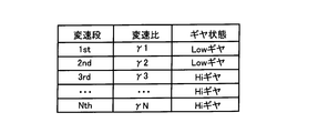
- the low gear start determining means 76 determines whether or not the gear ratio of the automatic transmission 18 exceeds a predetermined value ⁇ . For example, as shown in FIG. 5, it is defined for each gear position whether the gear ratio is a Low gear that exceeds the predetermined value ⁇ or a Hi gear that does not exceed the predetermined value ⁇ .
- the means 76 detects the current gear position, and determines whether or not the gear position is a low gear based on FIG.
- the speed ratio ⁇ 2 of the second speed stage corresponds to the predetermined value of the present invention.
- the current shift speed can also be detected by referring to the current running state from a shift command output from the electronic control unit 58 to the hydraulic control circuit 34 or a shift diagram (not shown).
- the engine start control means 72 is more effective than the engine start by the driver's acceleration request.
- the engagement pressure ⁇ P is obtained in advance through experiments or the like, and is set to a lower value than in the case of engine start due to the driver's acceleration request. Specifically, the engagement pressure ⁇ P is set such that the driver hardly feels a shock.
- FIG. 6 shows the relationship (torque characteristics) between the speed ratio e of the torque converter 16 and the efficiency ⁇ (power transmission efficiency).
- the pump rotational speed Np is equal to the electric motor rotational speed Nmg.
- the engine start control means 72 can absorb the shock generated when starting the engine by increasing the slip rotation speed Nslip by reducing the engagement pressure ⁇ P of the lockup clutch LU.
- the gear ratio of the automatic transmission 18 is the Low gear, the torque fluctuation transmitted to the output side (drive wheel 24 side) of the automatic transmission 18 increases, so the shock transmitted to the driver increases.
- the engine start control means 72 controls the engagement pressure ⁇ P of the lockup clutch LU to a normal value. This normal value is obtained in advance by experiments or the like, and is set to a hydraulic pressure higher than the engagement pressure ⁇ P at the time of engine start as required by the hybrid system. For example, when the accelerator pedal 61 is depressed by the driver, the driver's request for acceleration increases, while the sensitivity to shock decreases.
- FIG. 7 is a flowchart for explaining a main part of the control operation of the electronic control unit 58, that is, a control operation that can reduce a shock that is generated when the engine is started while the motor is running, for example, several msec to several tens msec. It is repeatedly executed with an extremely short cycle time.
- SA1 corresponding to the HV system required start determination means 74, it is determined whether or not the commanded engine start is due to a request from the hybrid system.
- SA2 corresponding to the low gear start determination means 76, the commanded engine start is due to the driver's acceleration request, and the current gear ratio of the automatic transmission 18 is low gear. It is determined whether or not.
- SA2 normal engine start control for controlling the engagement pressure ⁇ P of the lockup clutch LU to a predetermined value set in advance is executed.
- the normal engine start control is engine start control that is executed, for example, when the accelerator pedal 61 is depressed by the driver.
- FIG. 8 is a time chart for explaining a control state in engine starting from motor running.
- FIG. 8 (a) shows a control state at the time of engine start by, for example, a driver's acceleration request (accelerator pedal depression, etc.), and
- FIG. 8 (b) shows a request by the hybrid system corresponding to the present invention, or automatic
- the control state at the time of engine starting when the transmission 18 is a Low gear is shown.
- FIG. 8 (a) also corresponds to engine start by conventional control.
- the lockup torque T LU (transmittable torque) of the lockup clutch LU is reduced.
- the lockup torque TLU in FIG. 8 is a command value.
- the transmission torque reduction amount ⁇ T2 in FIG. 8B is larger than the transmission torque reduction amount ⁇ T1 in FIG.
- the engagement pressure ⁇ P of the lockup clutch LU is controlled to a lower value in FIG. 8B than in FIG. 8A.
- the slip rotation speed Nslip2 between the pump rotation speed (impeller rotation speed) Np and the turbine rotation speed Nt in FIG. 8B is greater than the slip rotation speed Nslip1 in FIG.
- the torque compensation value Tm ′ corresponds to a torque required for starting the engine 14 set in advance, and is a value obtained by subtracting the torque for motor travel from the total torque output from the electric motor 12.
- the transmission torque T KO clutch K0 increases at the same timing as the torque compensation value Tm 'of the motor 12, it is desirable torque compensation deviation becomes zero, actually hydraulic delay of the clutch K0 such Due to this, the torque compensation deviation occurs.
- the speed ratio e is smaller than that in FIG. 8 (a) based on the torque converter characteristics shown in FIG. 6, so that the reduction amount ⁇ 2 of the efficiency ⁇ is equal to the efficiency ⁇ in FIG. 8 (a).
- the amount of decrease is larger than ⁇ 1. Therefore, in FIG. 8 (b), the efficiency ⁇ is lower than that in FIG. 8 (a).
- torque fluctuations are absorbed by the slip of the fluid during torque transmission through the fluid of the torque converter 16. Therefore, as shown in FIG. 8 (b), the torque change ⁇ Tout2 output from the automatic transmission 18 is smaller than the torque change ⁇ Tout1 in FIG. 8 (a). That is, the shock due to the torque change is reduced.
- the engagement pressure of the lockup clutch 15 is higher than that when the engine is started due to the driver's acceleration request.
- the driver is highly sensitive to shock, and the engagement pressure ⁇ P of the lockup clutch 15 is reduced at the time of engine start due to the demand of the hybrid system, so that the ratio of torque transmission by the lockup clutch 15 is reduced.
- the gear ratio ⁇ of the automatic transmission 18 when the gear ratio ⁇ of the automatic transmission 18 is a low gear, when torque fluctuation generated at the time of engine start is input to the input shaft 18a of the automatic transmission 18, the torque fluctuation is changed. Although it is largely transmitted to the drive wheel 24 side, the torque fluctuation is effectively absorbed by the torque converter 15 by reducing the engagement pressure ⁇ P of the lockup clutch 15 at this time, so that the shock is reduced. .
- the engine start according to the request of the hybrid system corresponds to the case where the engine 14 is started for power generation or the case where the engine 14 is started to apply engine braking.
- the engine start due to the demand of the hybrid system is an engine start that is not intended by the driver, and the sensitivity of the driver to a shock at the time of engine start increases.
- the engagement pressure ⁇ P of the lock-up clutch 15 and increasing the ratio of torque transmission by the torque converter 16 fluid torque fluctuations at the start of the engine due to fluid slippage during torque transmission. It is effectively absorbed and shock can be reduced.
- the engine start due to the driver's acceleration request corresponds to the engine start when the accelerator pedal 61 is depressed by the driver.
- the driver's request for acceleration increases, but the sensitivity to shock decreases.
- the engagement pressure ⁇ P of the lock-up clutch 15 becomes higher than the engagement pressure ⁇ P set at the start of the hybrid system, so that the efficiency of the torque converter 16 is increased and a sense of incongruity due to insufficient driving force is felt. Can be reduced.
- the automatic transmission 18 is provided.
- the automatic transmission 18 is not necessarily required in the present invention, and can be applied to a configuration that does not include a transmission.
- the automatic transmission 18 is a stepped automatic transmission.
- the present invention can be applied to a continuously variable transmission such as a belt-type continuously variable transmission. it can.
- a continuously variable transmission for example, a gear ratio that is a threshold value for the Low gear and the Hi gear is set in advance.
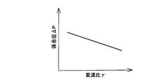
- the low gear and the Hi gear are set in two stages, but the engagement pressure ⁇ P of the lockup clutch LU is a relationship map of the engagement pressure ⁇ P with respect to the gear position as shown in FIG. May be stored, and the engagement pressure ⁇ P may be set based on the actual shift speed from the relationship map. In this case, the engagement pressure ⁇ P is set so as to decrease as the gear position increases, that is, the gear ratio increases.
- the gear ratio is a continuously variable transmission
- a relationship map of the engagement pressure ⁇ P of the lockup clutch 15 with respect to the gear ratio ⁇ as shown in FIG. 10 is stored in advance, and the actual gear ratio ⁇ is detected.
- the engagement pressure ⁇ P may be set from the detected gear ratio ⁇ .
- the torque converter 16 is used as the fluid transmission device.
- the torque converter 16 is not limited to the torque converter and may be a fluid coupling.
- the determination of the driver's acceleration request is determined based on the accelerator opening.
- the determination is based on the throttle valve opening, the accelerator opening and the throttle valve opening are determined. Since there is a one-to-one relationship with, there is virtually no change.
- Hybrid vehicle 12 Electric motor 14: Engine 16: Torque converter (fluid transmission device) 18: Automatic transmission (transmission) 24: Drive wheel ⁇ P: Engagement pressure of lockup clutch K0: Clutch LU: Lockup clutch
Landscapes
- Engineering & Computer Science (AREA)
- Transportation (AREA)
- Mechanical Engineering (AREA)
- Chemical & Material Sciences (AREA)
- Combustion & Propulsion (AREA)
- Automation & Control Theory (AREA)
- Power Engineering (AREA)
- Hybrid Electric Vehicles (AREA)
- Control Of Vehicle Engines Or Engines For Specific Uses (AREA)
Abstract
Description
12:電動機
14:エンジン
16:トルクコンバータ(流体伝動装置)
18:自動変速機(変速機)
24:駆動輪
ΔP:ロックアップクラッチの係合圧
K0:クラッチ
LU:ロックアップクラッチ
Claims (4)
- エンジンと、電動機と、該エンジンと該電動機との間の動力伝達経路に設けられているクラッチと、該電動機と駆動輪との間の動力伝達経路に設けられているロックアップクラッチを有する流体伝動装置とを、備えたハイブリッド車両の制御装置であって、
前記電動機によるモータ走行から前記エンジンを始動させる際は、前記クラッチを係合すると共に、前記ロックアップクラッチのスリップ制御を実行するものであり、
前記エンジンの始動がハイブリッドシステムの要求によるエンジン始動の場合には、運転者の加速要求によるエンジン始動の場合に比べて前記ロックアップクラッチの係合圧を低くすることを特徴とするハイブリッド車両の制御装置。 - 前記流体伝動装置と前記駆動輪との間には変速機が設けられており、
該変速機の変速比が所定値を越える場合、該所定値を越えない場合に比べて前記ロックアップクラッチの係合圧を低くすることを特徴とする請求項1のハイブリッド車両の制御装置。 - 前記ハイブリッドシステムの要求によるエンジン始動は、発電のためにエンジンを始動する場合、或いは、エンジンブレーキをかけるためにエンジンを始動する場合に対応することを特徴とする請求項1のハイブリッド車両の制御装置。
- 前記運転者の加速要求によるエンジン始動は、運転者によってアクセルペダルが踏み込まれた場合のエンジン始動に対応することを特徴とする請求項1のハイブリッド車両の制御装置。
Priority Applications (5)
| Application Number | Priority Date | Filing Date | Title |
|---|---|---|---|
| US14/000,694 US9180873B2 (en) | 2011-02-23 | 2011-02-23 | Control device of hybrid vehicle |
| DE112011104940.4T DE112011104940T5 (de) | 2011-02-23 | 2011-02-23 | Steuervorrichtung für ein Hybridfahrzeug |
| JP2013500767A JP5747980B2 (ja) | 2011-02-23 | 2011-02-23 | ハイブリッド車両の制御装置 |
| PCT/JP2011/053967 WO2012114472A1 (ja) | 2011-02-23 | 2011-02-23 | ハイブリッド車両の制御装置 |
| CN201180068412.3A CN103391868B (zh) | 2011-02-23 | 2011-02-23 | 混合动力车辆的控制装置 |
Applications Claiming Priority (1)
| Application Number | Priority Date | Filing Date | Title |
|---|---|---|---|
| PCT/JP2011/053967 WO2012114472A1 (ja) | 2011-02-23 | 2011-02-23 | ハイブリッド車両の制御装置 |
Publications (1)
| Publication Number | Publication Date |
|---|---|
| WO2012114472A1 true WO2012114472A1 (ja) | 2012-08-30 |
Family
ID=46720291
Family Applications (1)
| Application Number | Title | Priority Date | Filing Date |
|---|---|---|---|
| PCT/JP2011/053967 Ceased WO2012114472A1 (ja) | 2011-02-23 | 2011-02-23 | ハイブリッド車両の制御装置 |
Country Status (5)
| Country | Link |
|---|---|
| US (1) | US9180873B2 (ja) |
| JP (1) | JP5747980B2 (ja) |
| CN (1) | CN103391868B (ja) |
| DE (1) | DE112011104940T5 (ja) |
| WO (1) | WO2012114472A1 (ja) |
Cited By (2)
| Publication number | Priority date | Publication date | Assignee | Title |
|---|---|---|---|---|
| JP2014073705A (ja) * | 2012-10-02 | 2014-04-24 | Toyota Motor Corp | 車両用の制御装置 |
| WO2016159241A1 (ja) * | 2015-03-31 | 2016-10-06 | アイシン・エィ・ダブリュ株式会社 | 制御装置 |
Families Citing this family (16)
| Publication number | Priority date | Publication date | Assignee | Title |
|---|---|---|---|---|
| DE112011105948T5 (de) * | 2011-12-16 | 2014-09-11 | Toyota Jidosha Kabushiki Kaisha | Steuervorrichtung für ein Hybridfahrzeug |
| US9278685B2 (en) * | 2012-12-10 | 2016-03-08 | Ford Global Technologies, Llc | Method and system for adapting operation of a hybrid vehicle transmission torque converter lockup clutch |
| US9031722B2 (en) | 2012-12-10 | 2015-05-12 | Ford Global Technologies, Llc | Method and system for improving hybrid vehicle shifting |
| US9067594B2 (en) * | 2013-09-03 | 2015-06-30 | Ford Global Technologies, Llc | Methods and systems for hybrid driveline control |
| US9327721B2 (en) * | 2014-07-15 | 2016-05-03 | Ford Global Technologies, Llc | Methods and systems for starting an engine while a vehicle is creeping |
| DE102015217830A1 (de) * | 2015-09-17 | 2017-03-23 | Volkswagen Aktiengesellschaft | Kupplung für Kraftfahrzeug |
| DE102016203260A1 (de) * | 2016-02-29 | 2017-08-31 | Schaeffler Technologies AG & Co. KG | Verfahren zum Starten eines Verbrennungsmotors eines Hybridfahrzeugs und Steuereinheit zum Betreiben des Verfahrens |
| JP6874650B2 (ja) * | 2017-11-08 | 2021-05-19 | トヨタ自動車株式会社 | ハイブリッド車の制御装置 |
| DE102018211376B4 (de) * | 2018-07-10 | 2025-10-09 | Zf Friedrichshafen Ag | Rotorträger für eine elektrische Maschine |
| EP3763587B1 (en) | 2019-07-10 | 2021-08-11 | C.R.F. Società Consortile per Azioni | Method of controlling a hybrid propulsion system of a vehicle |
| DE102019124922A1 (de) * | 2019-09-17 | 2021-03-18 | Bayerische Motoren Werke Aktiengesellschaft | Steuereinheit und Verfahren zum Betrieb einer elektrischen Maschine eines Hybridantriebs |
| US11919401B2 (en) * | 2019-10-25 | 2024-03-05 | Exedy Globalparts Corporation | Compact P2 hybrid architecture |
| JP7502944B2 (ja) | 2020-09-08 | 2024-06-19 | 株式会社エクセディ | 駆動装置 |
| JP7490506B2 (ja) * | 2020-09-08 | 2024-05-27 | 株式会社エクセディ | 駆動装置 |
| JP7351821B2 (ja) * | 2020-09-30 | 2023-09-27 | トヨタ自動車株式会社 | 車両の制御装置 |
| JP7384775B2 (ja) | 2020-10-09 | 2023-11-21 | トヨタ自動車株式会社 | 車両の制御装置 |
Citations (6)
| Publication number | Priority date | Publication date | Assignee | Title |
|---|---|---|---|---|
| JP2004060861A (ja) * | 2002-07-31 | 2004-02-26 | Toyota Motor Corp | 車両の制御装置および制御方法 |
| JP2007069789A (ja) * | 2005-09-08 | 2007-03-22 | Nissan Motor Co Ltd | ハイブリッド車両のエンジン始動制御装置 |
| JP2007326557A (ja) * | 2006-04-19 | 2007-12-20 | Zahnradfab Friedrichshafen Ag | 少なくとも1つの内燃機関と、少なくとも1つの電動機と、を有する自動車のパラレルハイブリッドパワートレインを作動させるための方法 |
| WO2008132893A1 (ja) * | 2007-04-20 | 2008-11-06 | Toyota Jidosha Kabushiki Kaisha | 車両用動力伝達装置の制御装置 |
| JP2010507521A (ja) * | 2006-10-23 | 2010-03-11 | ローベルト ボツシユ ゲゼルシヤフト ミツト ベシユレンクテル ハフツング | ハイブリッド駆動装置の制御方法 |
| JP2010149748A (ja) * | 2008-12-25 | 2010-07-08 | Toyota Motor Corp | 車両の駆動装置 |
Family Cites Families (16)
| Publication number | Priority date | Publication date | Assignee | Title |
|---|---|---|---|---|
| JP4529335B2 (ja) * | 2001-08-31 | 2010-08-25 | アイシン・エィ・ダブリュ株式会社 | 車輌の制御装置 |
| JP3852595B2 (ja) | 2002-10-30 | 2006-11-29 | トヨタ自動車株式会社 | ハイブリッド自動車およびその制御方法 |
| JP4007364B2 (ja) | 2004-11-02 | 2007-11-14 | トヨタ自動車株式会社 | エンジン制御装置 |
| DE102006005468B4 (de) * | 2006-02-07 | 2017-09-21 | Zf Friedrichshafen Ag | Verfahren zum Betreiben eines Parallelhybridantriebsstranges eines Fahrzeuges |
| DE102006018058A1 (de) * | 2006-04-19 | 2007-11-08 | Zf Friedrichshafen Ag | Verfahren zum Betreiben eines Parallelhybridantriebsstranges eines Fahrzeuges mit mehreren Antriebaggregaten |
| DE102006018059A1 (de) * | 2006-04-19 | 2007-10-31 | Zf Friedrichshafen Ag | Verfahren zum Betreiben eines Parallelhybridantriebsstranges |
| JP5176421B2 (ja) * | 2007-08-03 | 2013-04-03 | 日産自動車株式会社 | ハイブリッド車両の制御装置 |
| JP2009126449A (ja) * | 2007-11-27 | 2009-06-11 | Toyota Motor Corp | 車両、内燃機関の始動制御装置及び内燃機関の始動方法 |
| JP5338300B2 (ja) | 2008-12-24 | 2013-11-13 | 日産自動車株式会社 | エンジン始動制御装置及びエンジン始動制御方法 |
| JP5170569B2 (ja) * | 2009-03-31 | 2013-03-27 | アイシン・エィ・ダブリュ株式会社 | ハイブリッド駆動装置 |
| US8109857B2 (en) * | 2009-04-23 | 2012-02-07 | GM Global Technology Operations LLC | Vehicle launch device having fluid coupling and electric machine |
| US8167771B2 (en) * | 2009-04-23 | 2012-05-01 | GM Global Technology Operations LLC | Vehicle launch device having fluid coupling |
| US8997956B2 (en) * | 2009-11-19 | 2015-04-07 | Aisin Aw Co., Ltd. | Vehicle drive device |
| US8622182B2 (en) * | 2009-11-19 | 2014-01-07 | Aisin Aw Co., Ltd. | Vehicle drive device |
| EP2543568A4 (en) * | 2010-03-01 | 2018-04-18 | Toyota Jidosha Kabushiki Kaisha | Power transmission control device |
| JP5293657B2 (ja) * | 2010-03-17 | 2013-09-18 | トヨタ自動車株式会社 | ハイブリッド車両の制御装置 |
-
2011
- 2011-02-23 DE DE112011104940.4T patent/DE112011104940T5/de not_active Ceased
- 2011-02-23 WO PCT/JP2011/053967 patent/WO2012114472A1/ja not_active Ceased
- 2011-02-23 JP JP2013500767A patent/JP5747980B2/ja not_active Expired - Fee Related
- 2011-02-23 US US14/000,694 patent/US9180873B2/en not_active Expired - Fee Related
- 2011-02-23 CN CN201180068412.3A patent/CN103391868B/zh not_active Expired - Fee Related
Patent Citations (6)
| Publication number | Priority date | Publication date | Assignee | Title |
|---|---|---|---|---|
| JP2004060861A (ja) * | 2002-07-31 | 2004-02-26 | Toyota Motor Corp | 車両の制御装置および制御方法 |
| JP2007069789A (ja) * | 2005-09-08 | 2007-03-22 | Nissan Motor Co Ltd | ハイブリッド車両のエンジン始動制御装置 |
| JP2007326557A (ja) * | 2006-04-19 | 2007-12-20 | Zahnradfab Friedrichshafen Ag | 少なくとも1つの内燃機関と、少なくとも1つの電動機と、を有する自動車のパラレルハイブリッドパワートレインを作動させるための方法 |
| JP2010507521A (ja) * | 2006-10-23 | 2010-03-11 | ローベルト ボツシユ ゲゼルシヤフト ミツト ベシユレンクテル ハフツング | ハイブリッド駆動装置の制御方法 |
| WO2008132893A1 (ja) * | 2007-04-20 | 2008-11-06 | Toyota Jidosha Kabushiki Kaisha | 車両用動力伝達装置の制御装置 |
| JP2010149748A (ja) * | 2008-12-25 | 2010-07-08 | Toyota Motor Corp | 車両の駆動装置 |
Cited By (4)
| Publication number | Priority date | Publication date | Assignee | Title |
|---|---|---|---|---|
| JP2014073705A (ja) * | 2012-10-02 | 2014-04-24 | Toyota Motor Corp | 車両用の制御装置 |
| WO2016159241A1 (ja) * | 2015-03-31 | 2016-10-06 | アイシン・エィ・ダブリュ株式会社 | 制御装置 |
| JPWO2016159241A1 (ja) * | 2015-03-31 | 2017-11-16 | アイシン・エィ・ダブリュ株式会社 | 制御装置 |
| US10279795B2 (en) | 2015-03-31 | 2019-05-07 | Aisin Aw Co., Ltd. | Control device |
Also Published As
| Publication number | Publication date |
|---|---|
| CN103391868A (zh) | 2013-11-13 |
| JPWO2012114472A1 (ja) | 2014-07-07 |
| US9180873B2 (en) | 2015-11-10 |
| DE112011104940T5 (de) | 2014-01-23 |
| CN103391868B (zh) | 2016-09-07 |
| JP5747980B2 (ja) | 2015-07-15 |
| US20130331228A1 (en) | 2013-12-12 |
Similar Documents
| Publication | Publication Date | Title |
|---|---|---|
| JP5747980B2 (ja) | ハイブリッド車両の制御装置 | |
| US7347803B2 (en) | Drive apparatus for hybrid vehicle and control method and control device thereof | |
| JP5573963B2 (ja) | ハイブリッド車両の制御装置 | |
| US9381908B2 (en) | Hybrid vehicle control device | |
| JPWO2010058470A1 (ja) | 車両用動力伝達装置の制御装置 | |
| JP2011245919A (ja) | ハイブリッド車両のアクセルペダル踏力制御装置 | |
| US10300908B2 (en) | Control device for starting an internal combustion engine during a shifting operation | |
| US9199636B2 (en) | Control device | |
| JP6098395B2 (ja) | ハイブリッド車両の制御装置 | |
| JP6052398B2 (ja) | ハイブリッド車両の制御装置 | |
| WO2014170749A1 (en) | Control device for vehicle | |
| JP7533437B2 (ja) | 車両の制御装置 | |
| JP2012086662A (ja) | 車両用エンジン始動制御装置 | |
| US20140038772A1 (en) | Traction Control System For A Hybrid Vehicle | |
| JP5012190B2 (ja) | ハイブリッド車 | |
| JP2006077607A (ja) | 車両の制御装置 | |
| JP7559732B2 (ja) | 車両の制御装置 | |
| US20250178584A1 (en) | Vehicle drive device | |
| JP2024005116A (ja) | 車両の制御装置 | |
| JP2012218559A (ja) | ハイブリッド車両の制御装置 | |
| WO2015019789A1 (ja) | フライホイール回生システム及びその制御方法 | |
| US12365328B2 (en) | Control device of vehicle | |
| JP6044179B2 (ja) | 車両制御装置 | |
| JP2023102681A (ja) | 車両の制御装置 | |
| JP2024005124A (ja) | 車両の制御装置 |
Legal Events
| Date | Code | Title | Description |
|---|---|---|---|
| 121 | Ep: the epo has been informed by wipo that ep was designated in this application |
Ref document number: 11859232 Country of ref document: EP Kind code of ref document: A1 |
|
| ENP | Entry into the national phase |
Ref document number: 2013500767 Country of ref document: JP Kind code of ref document: A |
|
| WWE | Wipo information: entry into national phase |
Ref document number: 14000694 Country of ref document: US |
|
| WWE | Wipo information: entry into national phase |
Ref document number: 1120111049404 Country of ref document: DE Ref document number: 112011104940 Country of ref document: DE |
|
| 122 | Ep: pct application non-entry in european phase |
Ref document number: 11859232 Country of ref document: EP Kind code of ref document: A1 |