WO2012111378A1 - 石炭の横型回転式乾燥機、石炭ボイラ設備及び石炭ボイラ設備の運転方法 - Google Patents
石炭の横型回転式乾燥機、石炭ボイラ設備及び石炭ボイラ設備の運転方法 Download PDFInfo
- Publication number
- WO2012111378A1 WO2012111378A1 PCT/JP2012/051056 JP2012051056W WO2012111378A1 WO 2012111378 A1 WO2012111378 A1 WO 2012111378A1 JP 2012051056 W JP2012051056 W JP 2012051056W WO 2012111378 A1 WO2012111378 A1 WO 2012111378A1
- Authority
- WO
- WIPO (PCT)
- Prior art keywords
- coal
- port
- discharge port
- fixed
- dry
- Prior art date
Links
Images


Classifications
-
- F—MECHANICAL ENGINEERING; LIGHTING; HEATING; WEAPONS; BLASTING
- F26—DRYING
- F26B—DRYING SOLID MATERIALS OR OBJECTS BY REMOVING LIQUID THEREFROM
- F26B17/00—Machines or apparatus for drying materials in loose, plastic, or fluidised form, e.g. granules, staple fibres, with progressive movement
- F26B17/30—Machines or apparatus for drying materials in loose, plastic, or fluidised form, e.g. granules, staple fibres, with progressive movement with movement performed by rotary or oscillating containers; with movement performed by rotary floors
- F26B17/32—Machines or apparatus for drying materials in loose, plastic, or fluidised form, e.g. granules, staple fibres, with progressive movement with movement performed by rotary or oscillating containers; with movement performed by rotary floors the movement being in a horizontal or slightly inclined plane
-
- F—MECHANICAL ENGINEERING; LIGHTING; HEATING; WEAPONS; BLASTING
- F26—DRYING
- F26B—DRYING SOLID MATERIALS OR OBJECTS BY REMOVING LIQUID THEREFROM
- F26B11/00—Machines or apparatus for drying solid materials or objects with movement which is non-progressive
- F26B11/02—Machines or apparatus for drying solid materials or objects with movement which is non-progressive in moving drums or other mainly-closed receptacles
- F26B11/026—Arrangements for charging or discharging the materials to be dried, e.g. discharging by reversing drum rotation, using spiral-type inserts
-
- C—CHEMISTRY; METALLURGY
- C10—PETROLEUM, GAS OR COKE INDUSTRIES; TECHNICAL GASES CONTAINING CARBON MONOXIDE; FUELS; LUBRICANTS; PEAT
- C10L—FUELS NOT OTHERWISE PROVIDED FOR; NATURAL GAS; SYNTHETIC NATURAL GAS OBTAINED BY PROCESSES NOT COVERED BY SUBCLASSES C10G, C10K; LIQUEFIED PETROLEUM GAS; ADDING MATERIALS TO FUELS OR FIRES TO REDUCE SMOKE OR UNDESIRABLE DEPOSITS OR TO FACILITATE SOOT REMOVAL; FIRELIGHTERS
- C10L9/00—Treating solid fuels to improve their combustion
- C10L9/08—Treating solid fuels to improve their combustion by heat treatments, e.g. calcining
-
- F—MECHANICAL ENGINEERING; LIGHTING; HEATING; WEAPONS; BLASTING
- F23—COMBUSTION APPARATUS; COMBUSTION PROCESSES
- F23K—FEEDING FUEL TO COMBUSTION APPARATUS
- F23K1/00—Preparation of lump or pulverulent fuel in readiness for delivery to combustion apparatus
-
- F—MECHANICAL ENGINEERING; LIGHTING; HEATING; WEAPONS; BLASTING
- F26—DRYING
- F26B—DRYING SOLID MATERIALS OR OBJECTS BY REMOVING LIQUID THEREFROM
- F26B21/00—Arrangements or duct systems, e.g. in combination with pallet boxes, for supplying and controlling air or gases for drying solid materials or objects
Definitions
- the present invention relates to a horizontal rotary dryer for coal that can be used in a thermal power plant or the like, a coal boiler facility equipped with the horizontal rotary dryer, and a method for operating the coal boiler facility.
- Factories that use heat such as thermal power plants, sugar factories, and pulp factories, are equipped with boilers that generate steam by heating water, and coal is used as part or all of the fuel.
- coal high-moisture content coal such as lignite and subbituminous coal may be used because it is inexpensive, and the coal is pulverized by a pulverizer such as a roller mill, It is burned with a burner attached to the boiler.
- a pulverizer such as a roller mill
- coal is pre-dried with a dryer and then pulverized with a pulverizer and used as fuel.
- coal such as lignite and subbituminous coal
- pulverized coal fine particles of 300 ⁇ m or less, which was present only at about 2%, increases to about 10%. Therefore, when transporting dry charcoal, etc., it is necessary to prevent pulverized coal from being scattered, which causes a problem that handling properties are poor.
- pulverized coal that does not need to be pulverized is also pulverized by a pulverizer, there is a problem that the pulverization efficiency is poor.
- the pulverizer is a roller mill or the like, if the amount of pulverized coal is large, vibration may occur and operation may become unstable. Therefore, in order to solve these problems, it is necessary to send dry coal to a classifier before pulverizing the dry coal with a pulverizer to remove pulverized coal in the dry coal.
- a horizontal rotary dryer is known as a coal dryer, and a typical example is a so-called steam tube dryer (STD) (see, for example, Patent Document 1).
- this steam tube dryer is mainly composed of a rotating cylinder 110 that rotates around an axis and a number of heating pipes 111 that are arranged inside the rotating cylinder 110 and that extend along the axial direction.
- a heat medium such as steam is passed through the heating pipe 111.
- Coal supplied (charged) from one end side of the rotating cylinder 110 is conveyed to the other end side as the rotating cylinder 110 rotates, and is heated by coming into contact with the heating tube 111 in the process of this conveying.
- the dried charcoal dried by this heating is discharged from a discharge port 112 provided on the other end side of the rotating cylinder 110.
- a carrier gas blow-in port 113 is provided on one end side of the rotating cylinder 110, and an exhaust gas provided on the other end side of the rotating cylinder 110 together with a gas such as steam generated inside the rotating cylinder 110.
- the air is exhausted from an exhaust port 122 communicating with the outlet 112.
- This steam tube dryer is extremely useful because it can stably dry coal and has many achievements.
- pulverized coal in the dry coal cannot be removed. Therefore, in order to avoid the problem caused by the pulverized coal, it is necessary to separately provide a classifier even when the coal is pre-dried using the conventional steam tube dryer.
- lignite when comparing lignite and bituminous coal, lignite has a low fixed carbon and a large amount of volatile matter, so the burning rate is fast, whereas bituminous coal has a high amount of fixed carbon and a low amount of volatile matter, so the combustion rate is slow. It is necessary to grind smaller than lignite.
- the horizontal rotary dryer is for removing pulverized coal in order to prevent dust generation, carbon adhesion, etc., and the problem is to change the size of pulverized coal to be removed according to the type of coal. It is not something to do.
- the main problems to be solved by the present invention are a horizontal rotary dryer for coal that can change the pulverized coal to be removed according to the type of coal, etc., a coal boiler facility equipped with this horizontal rotary dryer, and this coal It is in providing the operation method of boiler equipment.
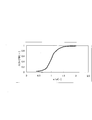
- This slip ratio is the ratio of pulverized coal discharged from the fixed exhaust port, and means that the higher the slip ratio, the greater the ratio of pulverized coal that is removed.
- the change in the slip ratio (the shape of the curve) varies depending on the shape of the classification hood, the internal structure, and the like, but the same result was obtained if these conditions were the same. Accordingly, the inventors have found that the ratio of fine powder to be removed and the particle size distribution can be controlled by changing the flow velocity (u), and have come up with the following invention that solves the above problems.
- a rotary cylinder having a coal supply port and a carrier gas blowing port on one end side, and a dry coal and exhaust gas discharge port on the other end side; Heating means for heating the coal in the rotating cylinder; A classification hood that covers the discharge port, has a fixed discharge port of dry charcoal at the bottom, and has a fixed exhaust port of exhaust gas at the top, Coal horizontal rotary dryer with Upward flow generating means for generating upward flow in the classification hood; A flow rate control means for controlling the flow rate of the upward flow, Discharging part or all of the pulverized coal in the dry coal from the fixed exhaust port by the upward flow, A horizontal rotary dryer for coal.
- Ascending flow generation means for generating upward flow in the classification hood and flow velocity control means for controlling the flow velocity of the upward flow are provided, so that the ratio and particle size distribution of pulverized coal discharged from the fixed exhaust port can be controlled.
- the pulverized coal to be removed can be changed according to the type of coal.
- a coal boiler facility comprising a coal dryer, a dry coal pulverizer dried by the dryer, and a boiler using the pulverized coal pulverized by the pulverizer as fuel,
- a rotary cylinder having a coal supply port and a carrier gas blowing port on one end side, and a dry coal and exhaust gas discharge port on the other end side; Heating means for heating the coal in the rotating cylinder;
- a classification hood that covers the discharge port, has a fixed discharge port of dry charcoal at the bottom, and has a fixed exhaust port of exhaust gas at the top, Upward flow generating means for generating upward flow in the classification hood, A flow rate control means for controlling the flow rate of the upward flow,
- a horizontal rotary dryer that discharges part or all of the pulverized coal in the dry coal from the fixed exhaust port by the upward flow is used as the dryer.
- Dispersing gas blowing means for blowing up the dispersing gas from the bottom of the classification hood as the upward flow generating means, As at least one of the carrier gas and the dispersion gas, exhaust gas exhausted from the fixed exhaust port and collected of the pulverized coal, and at least one of the exhaust gas of the boiler is used.
- At least one of the carrier gas and the dispersion gas As at least one of the carrier gas and the dispersion gas, at least one of the exhaust gas after being discharged from the fixed exhaust port and the pulverized coal is collected and the exhaust gas of the boiler is used, so that the thermal efficiency is excellent. In addition, since these exhaust gases have a low oxygen concentration, an explosion of coal dust can be prevented.
- a method for operating a coal boiler facility comprising: a coal dryer; a dry coal pulverizer dried by the dryer; and a boiler using the pulverized coal pulverized by the pulverizer as fuel.
- a rotary cylinder having a coal supply port and a carrier gas blowing port on one end side, and a dry coal and exhaust gas discharge port on the other end side; Heating means for heating the coal in the rotating cylinder;
- a horizontal rotary dryer provided with a classification hood that covers the discharge port, has a fixed discharge port for dry coal at the bottom, and has a fixed exhaust port for exhaust gas at the top, is used as the dryer.
- the discharged pulverized coal is controlled by controlling the flow rate of the upward flow.
- the dry coal discharged from the fixed discharge port of the horizontal rotary dryer is crushed by the pulverizer and then used as fuel for the boiler.
- the pulverized coal discharged from the fixed exhaust port of the horizontal rotary dryer is collected and used as fuel for the boiler.
- a horizontal rotary dryer for coal that can change the pulverized coal to be removed according to the type of coal, etc.
- a coal boiler facility equipped with the horizontal rotary dryer and a method for operating the coal boiler facility are provided. .
- FIG. 3 is a sectional view taken along line XX in FIG. 2. It is an enlarged view of classification food. It is an enlarged view of a dispersion gas blowing means. It is explanatory drawing of a dispersion gas blowing means. It is a modification of a classification hood and a dispersion gas blowing means. It is a modification of a classification hood and a dispersion gas blowing means. It is a figure which shows the relationship between the change of a flow rate, and a slip ratio. It is a perspective view of the conventional steam tube dryer.
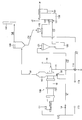
- FIG. 1 the equipment flowchart of the coal boiler equipment of this form was shown.
- the coal boiler equipment of this embodiment is supplied with a horizontal rotary dryer 100, a pulverizer 120 of dry coal C2 dried by the horizontal rotary dryer 100, and a pulverized coal C3 pulverized by the pulverizer 120 as fuel.
- Boiler 130 and so on.
- the “pulverized coal” means dry coal after being pulverized by a pulverizer, and is not distinguished from “pulverized coal” described later because the particle diameter is different.
- the horizontal rotary dryer 100 has a supply port for coal C1 made of lignite, subbituminous coal, and the like and a blow-in port for carrier gas G1 on one end side (left side of the paper), and dry coal C2 on the other end side (right side of the paper surface). And a rotary cylinder 10 having a discharge port 50 (see FIG. 3) for the exhaust gas G2, heating means for heating the coal C1 in the rotary cylinder 10, and a classification hood 55 for covering the discharge port 50 for the dry coal C2 and the exhaust gas G2. From, become the main. The details of the horizontal rotary dryer 100 will be described later.
- the carrier gas G1 is blown (supplied) into the rotary cylinder 10 by the blower 113, and exhausted from the rotary cylinder 10 as exhaust gas along with steam generated by heating the coal C1.
- the carrier gas G1 for example, any one of the exhaust gas G3 of the boiler 130, the inert gas such as nitrogen, the exhaust gas G4 after the pulverized coal C4 is collected (removed), the air, or the like is appropriately combined Gas can be used.
- the oxygen concentration of the carrier gas G1 usually 13% or less, preferably 12% or less). Therefore, it is preferable to use at least one of the exhaust gas G3 and the exhaust gas G4 as the carrier gas G1.
- both the exhaust gases G3 and G4 have a low oxygen concentration and a high temperature, even if they are used as the carrier gas G1, there is no possibility of preventing the heating of the coal C1.
- the oxygen concentration of the exhaust gas is measured (monitored), and when the measured value exceeds a predetermined value, the inert gas can be mixed or the amount of the mixed gas can be increased to control the oxygen concentration.
- the exhaust gas G4 after dust coal C4 is collected has shown the form discharged
- the dry charcoal C2 dried in the rotary cylinder 10 is discharged from the rotary cylinder 10 into the classification hood 55, and is then discharged from the fixed discharge port 57 (see FIG. 2) provided at the bottom (lower part) of the classification hood 55 to the outside of the apparatus. It is discharged and conveyed to the supply hopper 121 of the crusher 120 by a conveying means such as a belt conveyor.
- the dispersion gas N blowing means 58 is provided, and the desired pulverized coal C4 is classified from the dry coal C2, It discharges
- the dispersion gas N is directly blown into the classification hood 55 and blown up by the blower 113 used for blowing the carrier gas G1.
- a control valve 14 is provided on the flow path of the dispersion gas N, and the flow rate of the dispersion gas N is controlled by adjusting the opening degree (opening degree) of the control valve 14.
- the flow rate of the upward flow at is controlled.
- the control valve 14 functions as a flow rate control means for controlling the flow rate of the upward flow.
- a blower different from the blower 113 for the carrier gas G1 is provided, and this blower is used as the flow rate control means for the upward flow. It can also be.
- a separate blower is provided in this manner, the same kind of gas as the carrier gas G1 or a different kind of gas can be used as the dispersion gas N, but the same kind of gas is used from the viewpoint of processing stability. Is preferred.
- the pulverized coal C4 raised to the top by the upward flow in the classification hood 55 is discharged along with the exhaust gas G2 from the fixed exhaust port 56 provided in the top of the classification hood 55, and is collected by the dust collector 140. .
- the pulverized coal C4 collected by the dust collector 140 is conveyed to the pulverized coal hopper 150 and temporarily stored.
- the pulverized coal C4 stored in the pulverized coal hopper 150 is supplied to the burner 132 attached to the boiler 130 and burned as necessary.
- the supply of the pulverized coal C4 can be performed, for example, by air conveyance. In the illustrated example, a flow (air flow) of air A1 is formed by the blower 114, and pulverized coal C4 is conveyed by this air flow.
- the dry coal C2 conveyed to the supply hopper 121 and temporarily stored is cut out by the crusher 120 and pulverized.
- the finely pulverized pulverized coal C3 is supplied to a burner 131 attached to the boiler 130 and burned.
- the pulverized coal C4 is removed from the dry coal C2
- the pulverization by the pulverizer 120 is extremely efficient.
- vibrations are less likely to occur and the operation becomes unstable.
- the degree of fine pulverization of the dry coal C2 in the pulverizer 120 can be appropriately determined based on the type of coal, the combustion rate in the burner 131, and the like.
- the burning rate in the burner 131 is relatively fast, so that the degree of fine pulverization can be roughened.
- the burn rate in the burner 131 is relatively slow, so the degree of fine pulverization needs to be fine.
- FIG. 2 shows a horizontal rotary dryer (100) of this embodiment.
- the horizontal rotary dryer according to this embodiment includes a cylindrical rotary cylinder 10.
- the length of the rotary cylinder 10 in the axial direction is, for example, 10 to 30 m.
- the rotary cylinder 10 is installed such that its axis is slightly inclined with respect to the horizontal plane, and one end side (left side of the paper surface) of the rotary cylinder 10 is higher than the other end side (right side of the paper surface).
- two support units 20 and a motor unit 30 are installed so as to support the rotating cylinder 10.
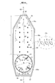
- the rotating cylinder 10 is rotatable about its own axis by the motor unit 30. As shown in FIG. 4, the rotating cylinder 10 rotates in one direction, in the illustrated example, in the counterclockwise direction (arrow R direction).
- the rotation speed is not particularly limited, but is usually less than 1 m / s.
- a large number of steam tubes (heating tubes) 11 are attached inside the rotary cylinder 10 so as to extend along the axial direction of the rotary cylinder 10.
- the steam tube 11 is made of, for example, a metal pipe, and a heat medium such as steam circulates therein.
- a plurality of steam tubes 11 can be arranged in the circumferential direction and the radial direction so as to form a concentric circle with respect to the axial center of the rotating cylinder 10.
- a plurality of discharge ports 50 are formed on the peripheral wall of the other end of the rotating cylinder 10. Through the plurality of discharge ports 50, the dry coal C2 and the exhaust gas are discharged and discharged from the rotary cylinder 10.
- the plurality of discharge ports 50 are arranged at appropriate intervals in the circumferential direction of the rotary cylinder 10 and form a row along the circumferential direction. In the example shown in the figure, this column has two columns, but it may be one column or a plurality of columns of three or more columns.
- all the shapes of each discharge port 50 are the same rectangular shape, it can also be set as a different shape or shapes other than square shapes, such as a circle.
- each of the scraping plate rows 60 includes a plurality of scraping plates 61 in the illustrated example that are spaced apart from each other at equal intervals.
- Each scraping plate 61 is formed of a thick metal, and has a hook shape in which a tip end portion is bent toward the front side in the rotation direction R of the rotary cylinder 10.
- the extension length of the scraping plate 61 can be, for example, 1/10 to 3/10 of the inner diameter D of the rotary cylinder 10. Further, each scraping plate 61 extends from the vicinity of a straight line that passes through the front end of the discharge port 50 located on the rear side in the rotation direction R of the rotating cylinder 10 and is parallel to the axial direction of the rotating cylinder 10. Are arranged to be. Therefore, the discharge port 50 does not exist in the immediate vicinity of the scraping plate 61, and the inner wall of the rotating cylinder 10 exists. As shown in FIG. 2, the scraping plate row 60 is disposed between the discharge port 50 and a supply port 41 described later in the rotary cylinder 10, and is the other end in the rotary cylinder 10 than the discharge port 50. Does not exist on the side. Further, the scraping plate row 60 is disposed in a portion near the discharge port 50 between the discharge port 50 and the supply port 41.
- an agitating means 65 for agitating coal C ⁇ b> 1 supplied (charged) into the rotary cylinder 10 is provided at one end of the rotary cylinder 10 with respect to the scraping plate row 60 inside the rotary cylinder 10. is set up.
- the stirring means 65 is also separated from the scraping plate row 60 arranged on the most end side inside the rotary cylinder 10.
- a well-known stud type, a reverse blade, etc. can be used, for example.
- it is particularly preferable to select the reverse blade for reasons such as the effect of separating (dispersing) pulverized coal and increasing the filling rate of dry coal whose volume specific gravity is reduced and the volume is reduced by drying.
- the rotary cylinder 10 is provided with a classification hood 55 capable of discharging dry coal C2 and exhaust gas G2 so as to cover the other end side having the plurality of discharge ports 50.
- the classification hood 55 is formed of a thick metal, and as shown in FIG. 5, the dry coal C2 that has been dried and classified (removal of pulverized coal C4) is fixed to the bottom surface of the bottom (lower) 55d.
- the exhaust port 57 has a fixed exhaust port 56 for the exhaust gas G2 on the top surface of the top (upper part) 55u. Further, as shown in FIG.
- the classification hood 55 is narrower as the top portion 55u heads toward the fixed exhaust port 56 in the width direction orthogonal to the axial direction of the rotary cylinder 10, and similarly, the bottom portion 55d has a width. The width becomes narrower toward the fixed outlet 57 with respect to the direction.
- the fixed exhaust port 56 and the fixed exhaust port 57 are located substantially at the center of the classification hood 55 in plan view.
- the inside of the classification hood 55 above the rotary cylinder 10 (range indicated by the symbol L) is a settling zone 90 which is a space filled with exhaust gas and the dispersed gas N from the rotary cylinder 10. That is, the classification hood 55 is provided so that the sedimentation zone 90 is formed above the rotary cylinder 10. Further, the classification hood 55 is fixed to the ground by means (not shown) so as not to rotate with the rotation of the rotary cylinder 10.
- the fixed exhaust port 56 opens in the vertical direction and is connected to the dust collecting means 140 described above. From the fixed exhaust port 56, exhaust gas G2 containing steam, dispersion gas N, pulverized coal C4, and the like generated as the carrier gas G1 and coal C1 are dried is discharged. On the other hand, the fixed discharge port 57 is also opened in the vertical direction, and is connected to the supply hopper 121 of the pulverizer 120. From the fixed discharge port 57, the dry coal C2 after the pulverized coal C4 is classified and removed is discharged.
- the horizontal rotary dryer 100 generates an upward flow in the classification hood 55 and controls the flow rate of the upward flow to control the particle size distribution and amount of the pulverized coal C4 discharged from the fixed exhaust port 56. Is to control.
- the particle size distribution and amount can be controlled more suitably. Specifically, when the separation distance L is shortened, the overall slip rate is increased, but this increase rate is larger for pulverized coal C4 having a relatively large diameter. Therefore, when the separation distance L is shortened, the pulverized coal C4 discharged from the fixed exhaust port 56 has a higher particle size distribution on the large diameter side.
- the separation distance L is L> 0.3D, preferably 0.8D ⁇ L ⁇ 4.0D, more preferably 1.0D ⁇ with respect to the inner diameter D of the rotary cylinder 10. L ⁇ 2.5D. Further, from the viewpoint of adjusting the particle size distribution of the pulverized coal C4 discharged from the fixed exhaust port 56, as shown in an enlarged manner in FIG.
- baffle plates 91 it is preferable to attach one or a plurality of baffle plates 91 to the inner wall surface 55a of the classification hood 55 that constitutes the classification hood 55.
- the large-diameter pulverized coal that collides with the baffle plate 91 falls and is discharged from the fixed discharge port 57 as it is.
- the small diameter pulverized coal that collides with the baffle plate 91 once falls a part of the pulverized coal rises again by the upward flow. Therefore, the particle size distribution of the pulverized coal C4 discharged from the fixed exhaust port 56 shows a low value on the large diameter side.
- the classification hood 55 extends in the axial direction of the rotary cylinder 10 in the sedimentation zone 90. If the classification hood 55 spreads in the axial direction in the settling zone 90, the collision rate between the pulverized coals or between the pulverized coal and the classification hood 55 (particularly the wall materials 55A and 55B at both ends in the axial direction of the classification hood 55) decreases. The particle size distribution of the pulverized coal C4 can be controlled more accurately. Note that spreading in the axial direction means spreading compared to the connection portion with the rotating cylinder 10.
- the sedimentation zone 90 does not need to extend in the axial direction over the entire length in the vertical direction.
- pulverized coal or the like is immediately after being discharged from the rotating cylinder 10 through the discharge port 50, and since it does not spread in a plane, it can not be spread in the axial direction as in the illustrated example.
- the top portion 55u of the classification hood 55 becomes narrower toward the fixed exhaust port 56 in the axial direction of the rotary cylinder 10 as illustrated.
- the extent of spreading of the classification hood 55 is preferably 1.5Z1 ⁇ Z2 ⁇ 6Z1, where Z1 is the axial length of the connecting portion with the rotary cylinder 10 and Z2 is the axial length of the spreading portion, and 2Z1 ⁇ More preferably, Z2 ⁇ 4Z1.
- the sinking zone 90 can be expanded in the width direction as shown in FIGS. 8 and 9, or can be expanded in both the width direction and the axial direction although not shown. How to widen the sedimentation zone 90 can be appropriately determined in consideration of surrounding facilities and the like. However, there is an advantage that the installation space of the entire horizontal rotary dryer can be narrowed by extending in the axial direction.
- a plurality of support members (62, 63) are provided between one axial wall material 55A and the other axial wall material 55B of the classification hood 55. Is provided. If the classification hood 55 spreads in the axial direction, the strength may decrease, but a plurality of support members (62, 63) are provided between one axial wall material 55A and the other axial wall material 55B. By providing, the strength of the classification hood 55 is maintained.
- the support members (62, 63) can also be provided between the one wall member 55A and the other wall member 55B of the portion that does not spread in the axial direction of the classification hood 55 as in the illustrated example.
- the support material for maintaining the strength of the classification hood 55 can be composed of only a straight bar, a pipe, or the like, but in this embodiment, the support is arranged on the pipe 62 and the pipe 62. It is comprised with the umbrella material 63.
- FIG. The umbrella material 63 has an umbrella shape with the center in the width direction protruding upward, and is arranged so as to extend along the extending direction of the pipe material 62. The presence of the umbrella material 63 prevents the dry coal C2 from being deposited on the pipe material 62.
- the umbrella material 63 itself may or may not have a function for maintaining the strength of the classification hood 55.
- the top portion 55u of the classification hood 55 is narrower toward the fixed exhaust port 56 in the width direction.
- the support members (62, 63) are preferably not positioned. If the upper portion 55u of the classification hood 55 becomes narrower toward the fixed exhaust port 56 in the width direction, as shown in FIG. 4, a flow (upflow) S1 along the wall material that becomes narrower is generated, The pulverized coal C4 rides on this flow S1. Therefore, the rising pulverized coal C4 does not collide with the top surface of the classification hood 55 and descend, and the particle size distribution of the pulverized coal C4 can be controlled more accurately.
- a flow S1 along the wall material is generated, and a flow S2 that rises vertically in the center is mainly generated, and the pulverized coal C4 is also on the flow S2. Therefore, if a plurality of support members (62, 63) are not positioned below the fixed exhaust port 56, the pulverized coal C4 riding on the flow S2 that rises vertically in the center collides with the support members (62, 63). There is no lowering, and the particle size distribution of the pulverized coal C4 can be controlled more accurately.
- the dispersed gas N serving as the upward flow generating means is disposed on the flow path of the dry coal C2 from the discharge port 50 of the rotary cylinder 10 to the fixed discharge port 57 by free fall or the like.
- a blowing means 58 is provided inside the classification hood 55. An upward flow is generated by blowing up the dispersed gas N, but especially when this blowing is performed on the flow path of the dry coal C2, the pulverized coal that has descended from the discharge port 50 together with the dry coal C2 is reliably blown up. Therefore, the particle size distribution of the pulverized coal C4 can be controlled more accurately.
- the specific form of the dispersion gas N blowing means 58 is not particularly limited, and may be configured by, for example, a dispersion plate made of a mesh material or the like and a means for blowing the dispersion gas N through the mesh material.
- a hole 58Ac is formed in the peripheral wall across the flow path of the dry coal C2 reaching the fixed discharge port 57.
- the pipe material 58A is provided, and the dispersion gas N is blown up from the hole 58Ac formed in the pipe material 58A.
- the dispersion gas N blowing means 58 is constituted by the pipe material 58 ⁇ / b> A crossing the flow path of the dry coal C ⁇ b> 2 reaching the fixed discharge port 57, consideration for guiding the dry coal C ⁇ b> 2 to the fixed discharge port 57. Is not necessary. Further, when the dispersion gas N is blown up from the hole 58Ac formed in the peripheral wall of the pipe material 58A, the blowing effect is reliably exerted on the pulverized coal in the dry coal C2.
- the holes 58Ac formed in the peripheral wall of the pipe material 58A are formed in a circular shape, and a plurality of holes 58Ac are formed at appropriate intervals in the extending direction of the pipe material 58A. Further, as shown in FIG. 7A, the hole 58Ac is formed so that the dispersed gas N blows up obliquely upward.
- a plurality of pipe members 58A are arranged in parallel with the axial direction of the rotary cylinder 10 in the vicinity of the fixed discharge port 57 as shown in the illustrated example.
- the dispersion gas N is blown to the dry coal C2 that is going to descend between the pipe materials 58A adjacent to each other, the pulverized coal is blown up by the dispersion gas N, while the dry coal C2 passes between the pipe materials 58A. It descends as it is and is discharged from the fixed discharge port 57.
- the pulverized coal blown up to the dispersion gas N soars in the classification hood 55, and a part of the pulverized coal C4 is discharged from the fixed exhaust port 56 in relation to the soaring speed (upflow speed).
- the flow velocity of the upward flow is controlled by controlling the flow velocity of the dispersion gas N blown up from each hole 58Ac.
- the flow velocity of the dispersion gas N is controlled in order to control the flow velocity of the upward flow in the classification hood 55, but the flow velocity of the upward flow is usually different depending on the parts such as the bottom and the top. Therefore, in determining the flow velocity of the upward flow, the flow velocity in the subsidence zone 90, particularly the center in the vertical direction of the subsidence zone 90 (the central portion when the separation distance L is divided into three equal parts) should be used as a reference. Recommend. Since pulverized coal is classified in the sedimentation zone 90, it is preferable to use the upward flow velocity in the sedimentation zone 90 as a reference.
- the slip rate tends to be lower than intended when the lower end portion in the vertical direction of the subsidence zone 90 is used as a reference, while the slip rate is higher than intended when the upper end portion in the vertical direction of the settling region 90 is used as a reference. Since there is a tendency, it is preferable to determine the flow velocity with reference to the center in the vertical direction of the sedimentation zone 90.
- the pipe material group composed of the plurality of pipe materials 58A can be provided in a plurality of stages separated in the vertical direction.
- the umbrella material 58B can also be arrange
- the umbrella material 58B has an umbrella shape with the center in the width direction protruding upward, and extends along the extending direction of the pipe material 58A. Due to the presence of the umbrella material 58B, the dry coal C2 is more reliably prevented from being deposited on the pipe material 58A.
- a supply pipe 70 and a drain pipe 71 for supplying steam J1 into a steam tube (heating pipe) 11 are provided on the other end side of the rotary cylinder 10.
- the drain water D discharged through the drain pipe 71 can be sent to the heat exchanger 115 and used for heating the air A1 used for conveying the pulverized coal C4.
- steam supplied to the steam tube 11 steam J2 generated by the boiler 130, bleed steam of a steam turbine using the steam J2, or the like can be used.
- a screw feeder 42 having a screw inside is installed so as to be fitted into the rotating cylinder 10.
- One end of the screw feeder 42 is provided with a driving means 43 such as a motor for rotating a screw provided inside the screw feeder 42.
- the supply port 41 of coal C1 is opened in the upper part of the screw feeder 42, and the inside of this supply port 41 and the screw feeder 42 is connected.
- the coal C ⁇ b> 1 to be dried is supplied into the screw feeder 42 from the supply port 41, and the screw installed inside the screw feeder 42 is rotated by the driving means 43 to be supplied into the rotary cylinder 10. It has become so. Further, the carrier gas G1 is also blown from the supply port 41 or another supply port (not shown), and the blown carrier gas G1 flows through the inside of the rotary cylinder 10 toward the other end side of the rotary cylinder 10.
- the coal C1 is supplied to the supply port 41 as shown in FIG.
- the coal C1 supplied from the supply port 41 is supplied to the inside of the rotary cylinder 10 by the screw feeder 42, and moves to the other end side of the rotary cylinder 10 while contacting and drying the steam tube 11 heated by the steam J1. To do.
- the carrier gas G1 blown from the supply port 41 provided on one end side of the rotary cylinder 10 or another supply port (not shown) passes through the rotary cylinder 10 and is also an exhaust port for discharging the dry coal C2.
- 50 is exhausted out of the rotary cylinder 10 as an exhaust gas accompanied by steam and the like.
- the exhaust gas is exhausted from the discharge port 50 along with the pulverized coal dispersed in the rotary cylinder 10 by the scraping plate 61.
- the exhaust gas exhausted from the exhaust port 50 is exhausted from the classification hood 55 through the fixed exhaust port 56 together with part of the pulverized coal.
- the dispersion gas N is supplied by the blowing means 58 of the dispersion gas N so as to be blown upward toward the classification hood 55, and an upward flow is formed.
- the flow rate of the dispersion gas N is made smaller than the flow rate of the exhaust gas normally exhausted from the exhaust port 50.
- the exhaust gas has a flow velocity of, for example, 5 to 10 m / s when exhausted from the discharge port 50. This flow rate is appropriately adjusted according to the area of the discharge port 50 and the amount of carrier gas G1 blown.
- Dry coal C2 falls in the rotary cylinder 10 and naturally falls from the discharge port 50 located on the lower side without accompanying exhaust gas.
- the naturally-dried dry coal C2 is not further blown up by the dispersed gas N, passes through the pipe material 58A, and is discharged from the fixed discharge port 57.
- the pulverized coal having a relatively large diameter is mounted on the exhaust gas or discharged from the discharge port 50 together with the dry coal C2, but is heavy and fixed by the upward flow. It is not conveyed to the exhaust port 56, falls downward, and is discharged from the fixed discharge port 57 together with the dry coal C2.
- pulverized coal in the dry coal C2 pulverized coal having a relatively small diameter is discharged from the discharge port 50 along with the exhaust gas or together with the dry coal C2, and conveyed to the fixed exhaust port 56 by the upward flow.
- the exhaust gas G2 is discharged from the fixed exhaust port 56 together with the exhaust gas G2.
- the scraper plate 61 is provided inside the rotary cylinder 10 as in the horizontal rotary dryer of this embodiment, the pulverized coal contained in the coal C1 (dry coal C2) is dispersed in the space inside the rotary cylinder 10. Therefore, the pulverized coal can be put on the exhaust gas, and the possibility that the pulverized coal is discharged from the discharge port 50 together with the dry coal C2 and is directly discharged from the fixed discharge port 57 is reduced. Therefore, the particle size distribution of the pulverized coal C4 can be controlled more accurately.
- each scraping plate 61 passes through the front end portion of the discharge port 50 located on the rear side with respect to the rotation direction R of the rotary cylinder 10 and is a straight line that is parallel to the axial direction of the rotary cylinder 10. If it arrange
- the scraper plate 61 when the scraper plate 61 is intermittently positioned so as to be spaced apart from each other at equal intervals in the circumferential direction of the rotary cylinder 10, the coal C1 (dry coal C2) can be efficiently scraped.
- a scraping plate 61 that extends from the inner wall of the rotary cylinder 10 toward the axial center and scrapes up the coal C1 (dry coal C2) with the rotation of the rotary cylinder 10 is spaced apart in the circumferential direction.
- the exhaust gas passes through the coal C1 (dry coal C2) falling from the scraping plate 61. Therefore, a large amount of pulverized coal can be accompanied by the exhaust gas, and the pulverized coal is mixed with the dry coal C2. The probability of being discharged is reduced.
- the scraping plate 61 increases the contact efficiency between the coal C1 and the steam tube 11, and has a secondary advantage of increasing the drying efficiency.
- the scraping plate 61 of the scraping plate row 60 on at least the other end side (downstream side) of the scraping plate row 60 has a front side edge of the discharge port 50 with reference to the rotation direction R of the rotary cylinder 10.
- the proximal end of the scraping plate 61 is in a position close to, and is in a positional relationship extending from the inner wall of the rotating cylinder 10 toward the axis. Therefore, a large amount of coal C1 (dry coal C2) can be held and scraped up with the next discharge port 50 on the rotational direction front side of the rotary cylinder 10.
- coal C1 dry coal C2
- coal C1 dry coal C2
- the scraping plate 61 extends from the base end toward the axis of the rotating cylinder 10 and the extending distal end portion is bent forward with respect to the rotation direction R of the rotating cylinder 10. Has been. Therefore, more coal C1 (dry coal C2) can be held and scraped up with the next discharge port 50 ahead of the rotating cylinder 10 in the rotational direction. As a result, the probability that coal C1 (dry coal C2) is more reliably agitated and pulverized coal is discharged in a state of being mixed with dry coal C2 is reduced.
- the fixed exhaust port 57 that does not move and the fixed exhaust port 56 provided at the top of the classification hood 55 are combined, the settling area between the exhaust port 50 and the fixed exhaust port 56 is combined.
- classification by upward flow is performed. That is, the desired pulverized coal C4 is discharged from the fixed exhaust port 56 along with the exhaust gas G2, and other than that, the pulverized coal C4 is dropped toward the fixed discharge port 57 to be discharged.
- the inside of the classification hood 55 above the rotary cylinder 10 is a sedimentation zone 90 that is a space filled with exhaust gas
- the relatively large diameter pulverized coal accompanying the exhaust gas falls by inertia in the sedimentation zone 90. Then, it is discharged from the fixed discharge port 57.
- the number of the scraping plates 61 per each scraping plate row 60 is not particularly limited as long as it is four, but may be four to six in order to secure the scraping capacity. preferable.
- the number of the discharge ports 50 per line is not particularly limited, but is preferably 10 to 17 in consideration of reduction of pressure loss, dispersion of pulverized coal, mechanical strength of the rotating cylinder 10 and the like.
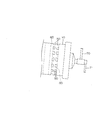
- FIG. 8 shows the classification hood 55 of this embodiment.
- the classification hood 55 of this embodiment is also installed on the one end side of the rotary cylinder 10 so as to cover the discharge port 50.
- This classification hood 55 is also fixed to the ground by means not shown, and does not rotate as the rotating cylinder 10 rotates.
- the top portion 55u is slightly wider than the intermediate portion 55c.
- the interior of the top 55u is a sedimentation zone 90 that is a space filled with exhaust gas or the like.
- the bottom 55d is narrower toward the fixed discharge port 57 in the width direction below the rotary cylinder 10.
- the bottom 55d of the classification hood 55 of the present embodiment is also provided with a dispersion gas N blowing means 58 as an upward flow generating means.
- the dispersion gas N blowing means 58 is composed of a dispersion plate 58a whose upper part is a fine mesh.
- the dispersion plate 58a is disposed on the floor surface of the bottom 55d and is inclined downward toward the fixed discharge port 57 to form a falling chute.
- the blowing means 58 is also supplied with the dispersed gas N, for example, as in the previous embodiment.
- the supplied dispersion gas N passes through the dispersion plate 58a and is blown up into the classification hood 55.
- the dispersion plate 58a since the dispersion plate 58a is inclined, the dry charcoal C2 can be quickly dropped to the fixed discharge port 57 as compared with the case where the dispersion plate 58a is horizontal.
- almost the entire bottom surface of the bottom portion 55d is the fixed discharge port 57, whereas in this embodiment, only the central portion of the bottom surface of the bottom portion 55d is the fixed discharge port 57 due to the arrangement of the dispersion plate 58a. It is said that. Therefore, there is a possibility that dry charcoal C2 is deposited on the bottom surface. In this respect, the previous form is preferable.
- the dispersion gas N blowing means 58 as the upward flow generating means is not provided on the flow path of the dry coal C2 from the discharge port 50 of the rotary cylinder 10 to the fixed discharge port 57. Therefore, there is a possibility that the dispersed gas N does not act directly on the dry coal C2, and the previous form is preferred also in this respect.
- FIG. 9 shows another type of classification hood 55.
- the classification hood 55 of the present embodiment is different from the above-described embodiment in the position of the dispersion gas N blowing means 58 and the position of the fixed discharge port 57 as the upward flow generating means.
- the fixed discharge port 57 does not open downward but opens sideways.
- a blowing means 58 for the dispersed gas N is arranged along with the fixed discharge port 57, and a dispersing plate 58a constituting the blowing means 58 is provided horizontally. This form is useful when there is no space below the classification hood 55.
- the classification hood 55 is provided with only one upward flow generation means (58).
- the upward flow generation means (58) includes two, three, four, or more. It is possible to provide a plurality. In the case where a plurality of ascending flow generating means (58) are provided, for example, it is preferable to arrange them separately in the top part 55u, the intermediate part 55c and the bottom part 55d of the classification hood 55.
- the method for generating the upward flow is not limited to the blowing up of the dispersed gas N, and if possible, a suction action (negative pressure) from above can be used.
- the use of the coal boiler facility of this embodiment is not particularly limited, and can be used in, for example, a factory using heat such as a thermal power plant, a sugar factory, and a pulp factory.
- the present invention can be appropriately applied to equipment that can use steam J2 generated by heating water W in boiler 130.
- the present invention can be applied to a horizontal rotary dryer for coal that can be used in a thermal power plant or the like, and a coal boiler facility equipped with this horizontal rotary dryer.
Landscapes
- Engineering & Computer Science (AREA)
- Chemical & Material Sciences (AREA)
- Mechanical Engineering (AREA)
- General Engineering & Computer Science (AREA)
- Combustion & Propulsion (AREA)
- Physics & Mathematics (AREA)
- Thermal Sciences (AREA)
- Oil, Petroleum & Natural Gas (AREA)
- Organic Chemistry (AREA)
- Drying Of Solid Materials (AREA)
- Solid Fuels And Fuel-Associated Substances (AREA)
- Crushing And Grinding (AREA)
Abstract
Description
一端側に石炭の供給口及びキャリアガスの吹込み口を有し、他端側に乾燥炭及び排ガスの排出口を有する回転筒と、
この回転筒内の石炭を加熱する加熱手段と、
前記排出口を覆い、底部に乾燥炭の固定排出口を有し、天部に排ガスの固定排気口を有する分級フードと、
が備わる石炭の横型回転式乾燥機であって、
前記分級フード内に上昇流を発生させる上昇流発生手段と、
前記上昇流の流速を制御する流速制御手段と、が備わり、
前記上昇流によって乾燥炭中の微粉炭の一部又は全部を前記固定排気口から排出する、
ことを特徴とする石炭の横型回転式乾燥機。
分級フード内に上昇流を発生させる上昇流発生手段と、上昇流の流速を制御する流速制御手段とが備わるため、固定排気口から排出される微粉炭の割合や粒径分布を制御することができ、石炭の種類等に応じて除去する微粉炭を変えることができる。
石炭の乾燥機と、この乾燥機で乾燥された乾燥炭の粉砕機と、この粉砕機で粉砕された粉砕炭を燃料とするボイラと、を有する石炭ボイラ設備であって、
一端側に石炭の供給口及びキャリアガスの吹込み口を有し、他端側に乾燥炭及び排ガスの排出口を有する回転筒と、
この回転筒内の石炭を加熱する加熱手段と、
前記排出口を覆い、底部に乾燥炭の固定排出口を有し、天部に排ガスの固定排気口を有する分級フードと、
この分級フード内に上昇流を発生させる上昇流発生手段と、
前記上昇流の流速を制御する流速制御手段と、が備わり、
前記上昇流によって乾燥炭中の微粉炭の一部又は全部を前記固定排気口から排出する、横型回転式乾燥機を前記乾燥機として用い、
この横型回転式乾燥機の固定排出口から排出された乾燥炭は前記粉砕機で粉砕した後、前記ボイラの燃料とし、
他方、前記横型回転式乾燥機の固定排気口から排出された微粉炭は集塵して、前記ボイラの燃料とする、
ことを特徴とする石炭ボイラ設備。
分級フード内に上昇流を発生させる上昇流発生手段と、上昇流の流速を制御する流速制御手段とが備わるため、請求項1記載の発明と同様の作用効果が奏せられる。したがって、固定排出口から排出された乾燥炭を粉砕機で粉砕するにおいて、ハンドリング性、粉砕効率等に関する前述微粉炭による問題が生じるのを防止することができる。しかも、固定排気口から排出される微粉炭を石炭の種類に応じた適切なものとすることができるため、別途、粉砕することなく、そのまま集塵してボイラの燃料とすることができる。
前記上昇流発生手段として、前記分級フードの底部から分散ガスを吹き上げる分散ガス吹上げ手段が備わり、
前記キャリアガス及び前記分散ガスの少なくとも一方として、前記固定排気口から排出され、前記微粉炭が集塵された後の排ガス、及び、前記ボイラの排ガスの少なくとも一方を利用する、
請求項2記載の石炭ボイラ設備。
キャリアガス及び分散ガスの少なくとも一方として、固定排気口から排出され微粉炭が集塵された後の排ガス、及び、ボイラの排ガスの少なくとも一方を利用するので熱効率に優れる。しかも、これらの排ガスは酸素濃度が低いため、炭塵爆発を防止することができる。
石炭の乾燥機と、この乾燥機で乾燥された乾燥炭の粉砕機と、この粉砕機で粉砕された粉砕炭を燃料とするボイラと、を有する石炭ボイラ設備の運転方法であって、
一端側に石炭の供給口及びキャリアガスの吹込み口を有し、他端側に乾燥炭及び排ガスの排出口を有する回転筒と、
この回転筒内の石炭を加熱する加熱手段と、
前記排出口を覆い、底部に乾燥炭の固定排出口を有し、天部に排ガスの固定排気口を有する分級フードと、が備わる横型回転式乾燥機を前記乾燥機として用い、
前記分級フード内に上昇流を発生させることによって乾燥炭中の微粉炭の一部又は全部を前記固定排気口から排出するにあたり、この排出する微粉炭を前記上昇流の流速を制御することによって制御し、
前記横型回転式乾燥機の固定排出口から排出された乾燥炭は前記粉砕機で粉砕した後、前記ボイラの燃料として使用し、
他方、前記横型回転式乾燥機の固定排気口から排出された微粉炭は集塵して、前記ボイラの燃料として使用する、
ことを特徴とする石炭ボイラ設備の運転方法。
分級フード内に上昇流を発生させることによって乾燥炭中の微粉炭の一部又は全部を固定排気口から排出するにあたり、この排出する微粉炭を上昇流の流速を制御することによって制御するため、請求項2記載の発明と同様の作用効果が奏せられる。
(石炭ボイラ設備)
図1に、本形態の石炭ボイラ設備の設備フロー図を示した。本形態の石炭ボイラ設備は、横型回転式乾燥機100と、この横型回転式乾燥機100で乾燥した乾燥炭C2の粉砕機120と、この粉砕機120で粉砕した粉砕炭C3が燃料として供給されるボイラ130と、から主になる。なお、「粉砕炭」とは、粉砕機で粉砕された後の乾燥炭を意味し、後述する「微粉炭」とは粒子径が異なるために区別されるというわけではない。
次に、横型回転式乾燥機100について、詳細に説明する。
図2に、本形態の横型回転式乾燥機(100)を示した。本形態の横型回転式乾燥機は、円筒状の回転筒10を有する。この回転筒10は、軸心方向の長さが、例えば10~30mとされる。回転筒10は、軸心が水平面に対して若干傾くようにして設置されており、回転筒10の一端側(紙面左側)が他端側(紙面右側)よりも高くなっている。回転筒10の下方には、2台の支持ユニット20及びモーターユニット30が回転筒10を支持するように設置されている。回転筒10は、モーターユニット30によって、自身の軸心回りに回転自在とされている。回転筒10は、図4に示すように、一方向に、図示例では反時計回り方向(矢印R方向)に回転する。この回転の速度は、特に限定されないが、通常、周速1m/s未満である。
本形態の横型回転式乾燥機で石炭C1を乾燥するにあたっては、図2に示すように、石炭C1を供給口41に供給する。供給口41から供給された石炭C1は、スクリューフィーダ42によって回転筒10内部に供給され、蒸気J1によって加熱されたスチームチューブ11に接触して加熱乾燥されつつ、回転筒10の他端側に移動する。
本形態の横型回転式乾燥機のように、掻上板61が回転筒10内部に設けられていると、石炭C1(乾燥炭C2)に含有される微粉炭が回転筒10内部の空間において分散するため、この微粉炭を排ガスに乗せることができ、乾燥炭C2と伴に排出口50から排出され、そのまま固定排出口57から排出されてしまう可能性が減る。したがって、微粉炭C4の粒径分布をより正確に制御することができる。
次に、横型回転式乾燥機(100)の変形例について、上記した形態と異なる点を中心に説明する。
図8に、本形態の分級フード55を示した。本形態の分級フード55も回転筒10の一端側に排出口50を覆うようにして設置される。この分級フード55も、図示しない手段によって地面に固定され、回転筒10の回動に伴う回動をしない。ただし、本形態の分級フード55は、中間部55cに比べて天部55uが若干幅広がりとなっている。この天部55uの内部は、排ガス等で満たされた空間である沈降域90である。また、底部55dは、回転筒10の下方において幅方向に関して固定排出口57に向かうに従って幅狭となっている。
図9に、別の形態の分級フード55を示した。本形態の分級フード55は、上昇流発生手段たる分散ガスNの吹上げ手段58の位置、固定排出口57の位置が上記形態と異なる。固定排出口57は、下方に向かって開口しておらず、側方に向かって開口している。この固定排出口57と並んで分散ガスNの吹上げ手段58が配置されており、この吹上げ手段58を構成する分散板58aが水平に設けられている。この形態は、分級フード55の下方にスペースがない場合等に有用である。
以上の形態例では、分級フード55に上昇流発生手段(58)を1つのみ備えた形態を示したが、上昇流発生手段(58)は、2つ、3つ、4つ又はそれ以上の複数備えることもできる。上昇流発生手段(58)を複数備える場合は、例えば、分級フード55の天部55u、中間部55c、底部55dに分けて配置すると好適である。また、上昇流を発生させるための方法は、分散ガスNの吹上げに限定されず、可能であれば上方からの吸引作用(負圧)を利用することもできる。
Claims (4)
- 一端側に石炭の供給口及びキャリアガスの吹込み口を有し、他端側に乾燥炭及び排ガスの排出口を有する回転筒と、
この回転筒内の石炭を加熱する加熱手段と、
前記排出口を覆い、底部に乾燥炭の固定排出口を有し、天部に排ガスの固定排気口を有する分級フードと、
が備わる石炭の横型回転式乾燥機であって、
前記分級フード内に上昇流を発生させる上昇流発生手段と、
前記上昇流の流速を制御する流速制御手段と、が備わり、
前記上昇流によって乾燥炭中の微粉炭の一部又は全部を前記固定排気口から排出する、
ことを特徴とする石炭の横型回転式乾燥機。 - 石炭の乾燥機と、この乾燥機で乾燥された乾燥炭の粉砕機と、この粉砕機で粉砕された粉砕炭を燃料とするボイラと、を有する石炭ボイラ設備であって、
一端側に石炭の供給口及びキャリアガスの吹込み口を有し、他端側に乾燥炭及び排ガスの排出口を有する回転筒と、
この回転筒内の石炭を加熱する加熱手段と、
前記排出口を覆い、底部に乾燥炭の固定排出口を有し、天部に排ガスの固定排気口を有する分級フードと、
この分級フード内に上昇流を発生させる上昇流発生手段と、
前記上昇流の流速を制御する流速制御手段と、が備わり、
前記上昇流によって乾燥炭中の微粉炭の一部又は全部を前記固定排気口から排出する、横型回転式乾燥機を前記乾燥機として用い、
この横型回転式乾燥機の固定排出口から排出された乾燥炭は前記粉砕機で粉砕した後、前記ボイラの燃料とし、
他方、前記横型回転式乾燥機の固定排気口から排出された微粉炭は集塵して、前記ボイラの燃料とする、
ことを特徴とする石炭ボイラ設備。 - 前記上昇流発生手段として、前記分級フードの底部から分散ガスを吹き上げる分散ガス吹上げ手段が備わり、
前記キャリアガス及び前記分散ガスの少なくとも一方として、前記固定排気口から排出され、前記微粉炭が集塵された後の排ガス、及び、前記ボイラの排ガスの少なくとも一方を利用する、
請求項2記載の石炭ボイラ設備。 - 石炭の乾燥機と、この乾燥機で乾燥された乾燥炭の粉砕機と、この粉砕機で粉砕された粉砕炭を燃料とするボイラと、を有する石炭ボイラ設備の運転方法であって、
一端側に石炭の供給口及びキャリアガスの吹込み口を有し、他端側に乾燥炭及び排ガスの排出口を有する回転筒と、
この回転筒内の石炭を加熱する加熱手段と、
前記排出口を覆い、底部に乾燥炭の固定排出口を有し、天部に排ガスの固定排気口を有する分級フードと、が備わる横型回転式乾燥機を前記乾燥機として用い、
前記分級フード内に上昇流を発生させることによって乾燥炭中の微粉炭の一部又は全部を前記固定排気口から排出するにあたり、この排出する微粉炭を前記上昇流の流速を制御することによって制御し、
前記横型回転式乾燥機の固定排出口から排出された乾燥炭は前記粉砕機で粉砕した後、前記ボイラの燃料として使用し、
他方、前記横型回転式乾燥機の固定排気口から排出された微粉炭は集塵して、前記ボイラの燃料として使用する、
ことを特徴とする石炭ボイラ設備の運転方法。
Priority Applications (2)
| Application Number | Priority Date | Filing Date | Title |
|---|---|---|---|
| KR1020137022540A KR101919071B1 (ko) | 2011-02-14 | 2012-01-19 | 석탄의 횡형 회전식 건조기, 석탄 보일러 설비 및 석탄 보일러 설비의 운전 방법 |
| AU2012218888A AU2012218888B2 (en) | 2011-02-14 | 2012-01-19 | Horizontal rotary dryer for coal, coal boiler plant, and method for operating coal boiler plant |
Applications Claiming Priority (2)
| Application Number | Priority Date | Filing Date | Title |
|---|---|---|---|
| JP2011028296A JP5794726B2 (ja) | 2011-02-14 | 2011-02-14 | 石炭ボイラ設備及び石炭ボイラ設備の運転方法 |
| JP2011-028296 | 2011-02-14 |
Publications (1)
| Publication Number | Publication Date |
|---|---|
| WO2012111378A1 true WO2012111378A1 (ja) | 2012-08-23 |
Family
ID=46672319
Family Applications (1)
| Application Number | Title | Priority Date | Filing Date |
|---|---|---|---|
| PCT/JP2012/051056 WO2012111378A1 (ja) | 2011-02-14 | 2012-01-19 | 石炭の横型回転式乾燥機、石炭ボイラ設備及び石炭ボイラ設備の運転方法 |
Country Status (5)
| Country | Link |
|---|---|
| JP (1) | JP5794726B2 (ja) |
| KR (1) | KR101919071B1 (ja) |
| AU (1) | AU2012218888B2 (ja) |
| TW (1) | TWI540204B (ja) |
| WO (1) | WO2012111378A1 (ja) |
Cited By (1)
| Publication number | Priority date | Publication date | Assignee | Title |
|---|---|---|---|---|
| WO2022203624A1 (en) * | 2021-03-26 | 2022-09-29 | Stinga Enerji Makina Uretim San Ve Tic. A.S | A drying unit for drying fuels in powder form by carbonization in oxygen-free environment |
Families Citing this family (4)
| Publication number | Priority date | Publication date | Assignee | Title |
|---|---|---|---|---|
| JP5736471B1 (ja) * | 2014-01-10 | 2015-06-17 | 月島機械株式会社 | 金属微粉スラリーの固液分離・乾燥設備及びその方法 |
| JP5946076B1 (ja) * | 2015-04-10 | 2016-07-05 | 月島機械株式会社 | 横型回転式乾燥機による乾燥方法及び乾燥システム |
| KR102362449B1 (ko) * | 2019-12-02 | 2022-02-15 | 한국전력공사 | 저연소성 연료의 미분탄 보일러 연소시스템 및 이를 이용한 연소방법 |
| CN113465359A (zh) * | 2021-06-07 | 2021-10-01 | 福州瑞华印制线路板有限公司 | 自动除尘磨板机 |
Citations (3)
| Publication number | Priority date | Publication date | Assignee | Title |
|---|---|---|---|---|
| JPH01107480U (ja) * | 1988-01-08 | 1989-07-20 | ||
| JPH0314584U (ja) * | 1989-06-09 | 1991-02-14 | ||
| WO2010084984A1 (ja) * | 2009-01-23 | 2010-07-29 | 月島機械株式会社 | 横型回転式乾燥機 |
Family Cites Families (5)
| Publication number | Priority date | Publication date | Assignee | Title |
|---|---|---|---|---|
| CA1332160C (en) * | 1989-05-23 | 1994-09-27 | Gary Francis Quig | Particle separator |
| JP2755338B2 (ja) * | 1991-07-09 | 1998-05-20 | 宇部興産株式会社 | 粉砕設備 |
| JP3825587B2 (ja) * | 1999-08-18 | 2006-09-27 | 新日本製鐵株式会社 | 石炭の乾燥方法及び乾燥装置 |
| CN102132097A (zh) * | 2008-08-28 | 2011-07-20 | 宇部兴产株式会社 | 煤的处理方法和处理系统 |
| JP5254062B2 (ja) * | 2009-01-23 | 2013-08-07 | 月島機械株式会社 | 横型回転式乾燥機 |
-
2011
- 2011-02-14 JP JP2011028296A patent/JP5794726B2/ja active Active
-
2012
- 2012-01-18 TW TW101102005A patent/TWI540204B/zh active
- 2012-01-19 KR KR1020137022540A patent/KR101919071B1/ko active IP Right Grant
- 2012-01-19 WO PCT/JP2012/051056 patent/WO2012111378A1/ja active Application Filing
- 2012-01-19 AU AU2012218888A patent/AU2012218888B2/en active Active
Patent Citations (3)
| Publication number | Priority date | Publication date | Assignee | Title |
|---|---|---|---|---|
| JPH01107480U (ja) * | 1988-01-08 | 1989-07-20 | ||
| JPH0314584U (ja) * | 1989-06-09 | 1991-02-14 | ||
| WO2010084984A1 (ja) * | 2009-01-23 | 2010-07-29 | 月島機械株式会社 | 横型回転式乾燥機 |
Cited By (1)
| Publication number | Priority date | Publication date | Assignee | Title |
|---|---|---|---|---|
| WO2022203624A1 (en) * | 2021-03-26 | 2022-09-29 | Stinga Enerji Makina Uretim San Ve Tic. A.S | A drying unit for drying fuels in powder form by carbonization in oxygen-free environment |
Also Published As
| Publication number | Publication date |
|---|---|
| JP2012167851A (ja) | 2012-09-06 |
| AU2012218888A1 (en) | 2013-10-03 |
| AU2012218888B2 (en) | 2016-05-12 |
| KR20140011323A (ko) | 2014-01-28 |
| TWI540204B (zh) | 2016-07-01 |
| TW201241167A (en) | 2012-10-16 |
| JP5794726B2 (ja) | 2015-10-14 |
| KR101919071B1 (ko) | 2019-02-08 |
Similar Documents
| Publication | Publication Date | Title |
|---|---|---|
| JP5905463B2 (ja) | 乾燥コンベア装置ならびにそれを備えた火力発電システム | |
| JP5812668B2 (ja) | 回転式分級機 | |
| JP5794726B2 (ja) | 石炭ボイラ設備及び石炭ボイラ設備の運転方法 | |
| JP5594941B2 (ja) | バイオマス粉砕装置、及び該装置の制御方法 | |
| JP6180218B2 (ja) | 固体燃料燃焼装置 | |
| JPH0317402A (ja) | 固体粒状燃料燃焼装置 | |
| JP6821371B2 (ja) | 炭素含有固体燃料粉砕装置及び炭素含有固体燃料粉砕装置の清掃方法 | |
| JP2012112595A (ja) | バイオマス・石炭混焼システムおよびバイオマス・石炭混焼方法 | |
| JP5645482B2 (ja) | バイオマス粉砕装置及びバイオマス・石炭混焼システム | |
| JP5497567B2 (ja) | 被処理物の乾燥分級方法 | |
| JP5230700B2 (ja) | 横型回転式乾燥機 | |
| JP5254061B2 (ja) | 横型回転式乾燥機 | |
| JP2014141619A (ja) | 改質炭の製造装置およびそれを備えた火力発電プラント | |
| JP7258581B2 (ja) | 粉砕機及びボイラシステム並びに粉砕機の運転方法 | |
| CN112138776B (zh) | 粉碎装置及锅炉系统以及粉碎装置的运转方法 | |
| CN109746084A (zh) | 粉碎机以及粉碎机的运转方法 | |
| JP5497566B2 (ja) | 横型回転式乾燥機 | |
| JP5388962B2 (ja) | 被処理物の乾燥分級方法 | |
| CN212092538U (zh) | 粉碎机及具备该粉碎机的固体燃料粉碎装置以及锅炉系统 | |
| WO2014198305A1 (en) | Rotary bottom disc incinerator | |
| JPH0376977B2 (ja) |
Legal Events
| Date | Code | Title | Description |
|---|---|---|---|
| 121 | Ep: the epo has been informed by wipo that ep was designated in this application |
Ref document number: 12746869 Country of ref document: EP Kind code of ref document: A1 |
|
| NENP | Non-entry into the national phase |
Ref country code: DE |
|
| ENP | Entry into the national phase |
Ref document number: 20137022540 Country of ref document: KR Kind code of ref document: A |
|
| ENP | Entry into the national phase |
Ref document number: 2012218888 Country of ref document: AU Date of ref document: 20120119 Kind code of ref document: A |
|
| 122 | Ep: pct application non-entry in european phase |
Ref document number: 12746869 Country of ref document: EP Kind code of ref document: A1 |