WO2012108466A1 - 車両の動力伝達制御装置 - Google Patents
車両の動力伝達制御装置 Download PDFInfo
- Publication number
- WO2012108466A1 WO2012108466A1 PCT/JP2012/052864 JP2012052864W WO2012108466A1 WO 2012108466 A1 WO2012108466 A1 WO 2012108466A1 JP 2012052864 W JP2012052864 W JP 2012052864W WO 2012108466 A1 WO2012108466 A1 WO 2012108466A1
- Authority
- WO
- WIPO (PCT)
- Prior art keywords
- vehicle
- shift
- control device
- power transmission
- torque
- Prior art date
Links
Images


Classifications
-
- B—PERFORMING OPERATIONS; TRANSPORTING
- B60—VEHICLES IN GENERAL
- B60W—CONJOINT CONTROL OF VEHICLE SUB-UNITS OF DIFFERENT TYPE OR DIFFERENT FUNCTION; CONTROL SYSTEMS SPECIALLY ADAPTED FOR HYBRID VEHICLES; ROAD VEHICLE DRIVE CONTROL SYSTEMS FOR PURPOSES NOT RELATED TO THE CONTROL OF A PARTICULAR SUB-UNIT
- B60W20/00—Control systems specially adapted for hybrid vehicles
- B60W20/30—Control strategies involving selection of transmission gear ratio
-
- B—PERFORMING OPERATIONS; TRANSPORTING
- B60—VEHICLES IN GENERAL
- B60K—ARRANGEMENT OR MOUNTING OF PROPULSION UNITS OR OF TRANSMISSIONS IN VEHICLES; ARRANGEMENT OR MOUNTING OF PLURAL DIVERSE PRIME-MOVERS IN VEHICLES; AUXILIARY DRIVES FOR VEHICLES; INSTRUMENTATION OR DASHBOARDS FOR VEHICLES; ARRANGEMENTS IN CONNECTION WITH COOLING, AIR INTAKE, GAS EXHAUST OR FUEL SUPPLY OF PROPULSION UNITS IN VEHICLES
- B60K6/00—Arrangement or mounting of plural diverse prime-movers for mutual or common propulsion, e.g. hybrid propulsion systems comprising electric motors and internal combustion engines ; Control systems therefor, i.e. systems controlling two or more prime movers, or controlling one of these prime movers and any of the transmission, drive or drive units Informative references: mechanical gearings with secondary electric drive F16H3/72; arrangements for handling mechanical energy structurally associated with the dynamo-electric machine H02K7/00; machines comprising structurally interrelated motor and generator parts H02K51/00; dynamo-electric machines not otherwise provided for in H02K see H02K99/00
- B60K6/20—Arrangement or mounting of plural diverse prime-movers for mutual or common propulsion, e.g. hybrid propulsion systems comprising electric motors and internal combustion engines ; Control systems therefor, i.e. systems controlling two or more prime movers, or controlling one of these prime movers and any of the transmission, drive or drive units Informative references: mechanical gearings with secondary electric drive F16H3/72; arrangements for handling mechanical energy structurally associated with the dynamo-electric machine H02K7/00; machines comprising structurally interrelated motor and generator parts H02K51/00; dynamo-electric machines not otherwise provided for in H02K see H02K99/00 the prime-movers consisting of electric motors and internal combustion engines, e.g. HEVs
- B60K6/42—Arrangement or mounting of plural diverse prime-movers for mutual or common propulsion, e.g. hybrid propulsion systems comprising electric motors and internal combustion engines ; Control systems therefor, i.e. systems controlling two or more prime movers, or controlling one of these prime movers and any of the transmission, drive or drive units Informative references: mechanical gearings with secondary electric drive F16H3/72; arrangements for handling mechanical energy structurally associated with the dynamo-electric machine H02K7/00; machines comprising structurally interrelated motor and generator parts H02K51/00; dynamo-electric machines not otherwise provided for in H02K see H02K99/00 the prime-movers consisting of electric motors and internal combustion engines, e.g. HEVs characterised by the architecture of the hybrid electric vehicle
- B60K6/48—Parallel type
-
- B—PERFORMING OPERATIONS; TRANSPORTING
- B60—VEHICLES IN GENERAL
- B60L—PROPULSION OF ELECTRICALLY-PROPELLED VEHICLES; SUPPLYING ELECTRIC POWER FOR AUXILIARY EQUIPMENT OF ELECTRICALLY-PROPELLED VEHICLES; ELECTRODYNAMIC BRAKE SYSTEMS FOR VEHICLES IN GENERAL; MAGNETIC SUSPENSION OR LEVITATION FOR VEHICLES; MONITORING OPERATING VARIABLES OF ELECTRICALLY-PROPELLED VEHICLES; ELECTRIC SAFETY DEVICES FOR ELECTRICALLY-PROPELLED VEHICLES
- B60L15/00—Methods, circuits, or devices for controlling the traction-motor speed of electrically-propelled vehicles
- B60L15/20—Methods, circuits, or devices for controlling the traction-motor speed of electrically-propelled vehicles for control of the vehicle or its driving motor to achieve a desired performance, e.g. speed, torque, programmed variation of speed
-
- B—PERFORMING OPERATIONS; TRANSPORTING
- B60—VEHICLES IN GENERAL
- B60L—PROPULSION OF ELECTRICALLY-PROPELLED VEHICLES; SUPPLYING ELECTRIC POWER FOR AUXILIARY EQUIPMENT OF ELECTRICALLY-PROPELLED VEHICLES; ELECTRODYNAMIC BRAKE SYSTEMS FOR VEHICLES IN GENERAL; MAGNETIC SUSPENSION OR LEVITATION FOR VEHICLES; MONITORING OPERATING VARIABLES OF ELECTRICALLY-PROPELLED VEHICLES; ELECTRIC SAFETY DEVICES FOR ELECTRICALLY-PROPELLED VEHICLES
- B60L50/00—Electric propulsion with power supplied within the vehicle
- B60L50/10—Electric propulsion with power supplied within the vehicle using propulsion power supplied by engine-driven generators, e.g. generators driven by combustion engines
- B60L50/16—Electric propulsion with power supplied within the vehicle using propulsion power supplied by engine-driven generators, e.g. generators driven by combustion engines with provision for separate direct mechanical propulsion
-
- B—PERFORMING OPERATIONS; TRANSPORTING
- B60—VEHICLES IN GENERAL
- B60L—PROPULSION OF ELECTRICALLY-PROPELLED VEHICLES; SUPPLYING ELECTRIC POWER FOR AUXILIARY EQUIPMENT OF ELECTRICALLY-PROPELLED VEHICLES; ELECTRODYNAMIC BRAKE SYSTEMS FOR VEHICLES IN GENERAL; MAGNETIC SUSPENSION OR LEVITATION FOR VEHICLES; MONITORING OPERATING VARIABLES OF ELECTRICALLY-PROPELLED VEHICLES; ELECTRIC SAFETY DEVICES FOR ELECTRICALLY-PROPELLED VEHICLES
- B60L58/00—Methods or circuit arrangements for monitoring or controlling batteries or fuel cells, specially adapted for electric vehicles
- B60L58/10—Methods or circuit arrangements for monitoring or controlling batteries or fuel cells, specially adapted for electric vehicles for monitoring or controlling batteries
- B60L58/12—Methods or circuit arrangements for monitoring or controlling batteries or fuel cells, specially adapted for electric vehicles for monitoring or controlling batteries responding to state of charge [SoC]
-
- B—PERFORMING OPERATIONS; TRANSPORTING
- B60—VEHICLES IN GENERAL
- B60W—CONJOINT CONTROL OF VEHICLE SUB-UNITS OF DIFFERENT TYPE OR DIFFERENT FUNCTION; CONTROL SYSTEMS SPECIALLY ADAPTED FOR HYBRID VEHICLES; ROAD VEHICLE DRIVE CONTROL SYSTEMS FOR PURPOSES NOT RELATED TO THE CONTROL OF A PARTICULAR SUB-UNIT
- B60W10/00—Conjoint control of vehicle sub-units of different type or different function
- B60W10/02—Conjoint control of vehicle sub-units of different type or different function including control of driveline clutches
-
- B—PERFORMING OPERATIONS; TRANSPORTING
- B60—VEHICLES IN GENERAL
- B60W—CONJOINT CONTROL OF VEHICLE SUB-UNITS OF DIFFERENT TYPE OR DIFFERENT FUNCTION; CONTROL SYSTEMS SPECIALLY ADAPTED FOR HYBRID VEHICLES; ROAD VEHICLE DRIVE CONTROL SYSTEMS FOR PURPOSES NOT RELATED TO THE CONTROL OF A PARTICULAR SUB-UNIT
- B60W10/00—Conjoint control of vehicle sub-units of different type or different function
- B60W10/04—Conjoint control of vehicle sub-units of different type or different function including control of propulsion units
- B60W10/06—Conjoint control of vehicle sub-units of different type or different function including control of propulsion units including control of combustion engines
-
- B—PERFORMING OPERATIONS; TRANSPORTING
- B60—VEHICLES IN GENERAL
- B60W—CONJOINT CONTROL OF VEHICLE SUB-UNITS OF DIFFERENT TYPE OR DIFFERENT FUNCTION; CONTROL SYSTEMS SPECIALLY ADAPTED FOR HYBRID VEHICLES; ROAD VEHICLE DRIVE CONTROL SYSTEMS FOR PURPOSES NOT RELATED TO THE CONTROL OF A PARTICULAR SUB-UNIT
- B60W10/00—Conjoint control of vehicle sub-units of different type or different function
- B60W10/04—Conjoint control of vehicle sub-units of different type or different function including control of propulsion units
- B60W10/08—Conjoint control of vehicle sub-units of different type or different function including control of propulsion units including control of electric propulsion units, e.g. motors or generators
-
- B—PERFORMING OPERATIONS; TRANSPORTING
- B60—VEHICLES IN GENERAL
- B60W—CONJOINT CONTROL OF VEHICLE SUB-UNITS OF DIFFERENT TYPE OR DIFFERENT FUNCTION; CONTROL SYSTEMS SPECIALLY ADAPTED FOR HYBRID VEHICLES; ROAD VEHICLE DRIVE CONTROL SYSTEMS FOR PURPOSES NOT RELATED TO THE CONTROL OF A PARTICULAR SUB-UNIT
- B60W10/00—Conjoint control of vehicle sub-units of different type or different function
- B60W10/10—Conjoint control of vehicle sub-units of different type or different function including control of change-speed gearings
- B60W10/11—Stepped gearings
-
- B—PERFORMING OPERATIONS; TRANSPORTING
- B60—VEHICLES IN GENERAL
- B60W—CONJOINT CONTROL OF VEHICLE SUB-UNITS OF DIFFERENT TYPE OR DIFFERENT FUNCTION; CONTROL SYSTEMS SPECIALLY ADAPTED FOR HYBRID VEHICLES; ROAD VEHICLE DRIVE CONTROL SYSTEMS FOR PURPOSES NOT RELATED TO THE CONTROL OF A PARTICULAR SUB-UNIT
- B60W10/00—Conjoint control of vehicle sub-units of different type or different function
- B60W10/24—Conjoint control of vehicle sub-units of different type or different function including control of energy storage means
- B60W10/26—Conjoint control of vehicle sub-units of different type or different function including control of energy storage means for electrical energy, e.g. batteries or capacitors
-
- B—PERFORMING OPERATIONS; TRANSPORTING
- B60—VEHICLES IN GENERAL
- B60W—CONJOINT CONTROL OF VEHICLE SUB-UNITS OF DIFFERENT TYPE OR DIFFERENT FUNCTION; CONTROL SYSTEMS SPECIALLY ADAPTED FOR HYBRID VEHICLES; ROAD VEHICLE DRIVE CONTROL SYSTEMS FOR PURPOSES NOT RELATED TO THE CONTROL OF A PARTICULAR SUB-UNIT
- B60W20/00—Control systems specially adapted for hybrid vehicles
- B60W20/10—Controlling the power contribution of each of the prime movers to meet required power demand
- B60W20/13—Controlling the power contribution of each of the prime movers to meet required power demand in order to stay within battery power input or output limits; in order to prevent overcharging or battery depletion
-
- B—PERFORMING OPERATIONS; TRANSPORTING
- B60—VEHICLES IN GENERAL
- B60W—CONJOINT CONTROL OF VEHICLE SUB-UNITS OF DIFFERENT TYPE OR DIFFERENT FUNCTION; CONTROL SYSTEMS SPECIALLY ADAPTED FOR HYBRID VEHICLES; ROAD VEHICLE DRIVE CONTROL SYSTEMS FOR PURPOSES NOT RELATED TO THE CONTROL OF A PARTICULAR SUB-UNIT
- B60W30/00—Purposes of road vehicle drive control systems not related to the control of a particular sub-unit, e.g. of systems using conjoint control of vehicle sub-units, or advanced driver assistance systems for ensuring comfort, stability and safety or drive control systems for propelling or retarding the vehicle
- B60W30/18—Propelling the vehicle
- B60W30/18009—Propelling the vehicle related to particular drive situations
- B60W30/18054—Propelling the vehicle related to particular drive situations at stand still, e.g. engine in idling state
-
- F—MECHANICAL ENGINEERING; LIGHTING; HEATING; WEAPONS; BLASTING
- F02—COMBUSTION ENGINES; HOT-GAS OR COMBUSTION-PRODUCT ENGINE PLANTS
- F02D—CONTROLLING COMBUSTION ENGINES
- F02D29/00—Controlling engines, such controlling being peculiar to the devices driven thereby, the devices being other than parts or accessories essential to engine operation, e.g. controlling of engines by signals external thereto
- F02D29/02—Controlling engines, such controlling being peculiar to the devices driven thereby, the devices being other than parts or accessories essential to engine operation, e.g. controlling of engines by signals external thereto peculiar to engines driving vehicles; peculiar to engines driving variable pitch propellers
-
- B—PERFORMING OPERATIONS; TRANSPORTING
- B60—VEHICLES IN GENERAL
- B60L—PROPULSION OF ELECTRICALLY-PROPELLED VEHICLES; SUPPLYING ELECTRIC POWER FOR AUXILIARY EQUIPMENT OF ELECTRICALLY-PROPELLED VEHICLES; ELECTRODYNAMIC BRAKE SYSTEMS FOR VEHICLES IN GENERAL; MAGNETIC SUSPENSION OR LEVITATION FOR VEHICLES; MONITORING OPERATING VARIABLES OF ELECTRICALLY-PROPELLED VEHICLES; ELECTRIC SAFETY DEVICES FOR ELECTRICALLY-PROPELLED VEHICLES
- B60L2210/00—Converter types
- B60L2210/40—DC to AC converters
-
- B—PERFORMING OPERATIONS; TRANSPORTING
- B60—VEHICLES IN GENERAL
- B60L—PROPULSION OF ELECTRICALLY-PROPELLED VEHICLES; SUPPLYING ELECTRIC POWER FOR AUXILIARY EQUIPMENT OF ELECTRICALLY-PROPELLED VEHICLES; ELECTRODYNAMIC BRAKE SYSTEMS FOR VEHICLES IN GENERAL; MAGNETIC SUSPENSION OR LEVITATION FOR VEHICLES; MONITORING OPERATING VARIABLES OF ELECTRICALLY-PROPELLED VEHICLES; ELECTRIC SAFETY DEVICES FOR ELECTRICALLY-PROPELLED VEHICLES
- B60L2220/00—Electrical machine types; Structures or applications thereof
- B60L2220/10—Electrical machine types
- B60L2220/14—Synchronous machines
-
- B—PERFORMING OPERATIONS; TRANSPORTING
- B60—VEHICLES IN GENERAL
- B60L—PROPULSION OF ELECTRICALLY-PROPELLED VEHICLES; SUPPLYING ELECTRIC POWER FOR AUXILIARY EQUIPMENT OF ELECTRICALLY-PROPELLED VEHICLES; ELECTRODYNAMIC BRAKE SYSTEMS FOR VEHICLES IN GENERAL; MAGNETIC SUSPENSION OR LEVITATION FOR VEHICLES; MONITORING OPERATING VARIABLES OF ELECTRICALLY-PROPELLED VEHICLES; ELECTRIC SAFETY DEVICES FOR ELECTRICALLY-PROPELLED VEHICLES
- B60L2240/00—Control parameters of input or output; Target parameters
- B60L2240/40—Drive Train control parameters
- B60L2240/42—Drive Train control parameters related to electric machines
- B60L2240/423—Torque
-
- B—PERFORMING OPERATIONS; TRANSPORTING
- B60—VEHICLES IN GENERAL
- B60L—PROPULSION OF ELECTRICALLY-PROPELLED VEHICLES; SUPPLYING ELECTRIC POWER FOR AUXILIARY EQUIPMENT OF ELECTRICALLY-PROPELLED VEHICLES; ELECTRODYNAMIC BRAKE SYSTEMS FOR VEHICLES IN GENERAL; MAGNETIC SUSPENSION OR LEVITATION FOR VEHICLES; MONITORING OPERATING VARIABLES OF ELECTRICALLY-PROPELLED VEHICLES; ELECTRIC SAFETY DEVICES FOR ELECTRICALLY-PROPELLED VEHICLES
- B60L2240/00—Control parameters of input or output; Target parameters
- B60L2240/40—Drive Train control parameters
- B60L2240/44—Drive Train control parameters related to combustion engines
- B60L2240/443—Torque
-
- B—PERFORMING OPERATIONS; TRANSPORTING
- B60—VEHICLES IN GENERAL
- B60L—PROPULSION OF ELECTRICALLY-PROPELLED VEHICLES; SUPPLYING ELECTRIC POWER FOR AUXILIARY EQUIPMENT OF ELECTRICALLY-PROPELLED VEHICLES; ELECTRODYNAMIC BRAKE SYSTEMS FOR VEHICLES IN GENERAL; MAGNETIC SUSPENSION OR LEVITATION FOR VEHICLES; MONITORING OPERATING VARIABLES OF ELECTRICALLY-PROPELLED VEHICLES; ELECTRIC SAFETY DEVICES FOR ELECTRICALLY-PROPELLED VEHICLES
- B60L2250/00—Driver interactions
- B60L2250/26—Driver interactions by pedal actuation
-
- B—PERFORMING OPERATIONS; TRANSPORTING
- B60—VEHICLES IN GENERAL
- B60W—CONJOINT CONTROL OF VEHICLE SUB-UNITS OF DIFFERENT TYPE OR DIFFERENT FUNCTION; CONTROL SYSTEMS SPECIALLY ADAPTED FOR HYBRID VEHICLES; ROAD VEHICLE DRIVE CONTROL SYSTEMS FOR PURPOSES NOT RELATED TO THE CONTROL OF A PARTICULAR SUB-UNIT
- B60W2510/00—Input parameters relating to a particular sub-units
- B60W2510/02—Clutches
- B60W2510/0208—Clutch engagement state, e.g. engaged or disengaged
-
- B—PERFORMING OPERATIONS; TRANSPORTING
- B60—VEHICLES IN GENERAL
- B60W—CONJOINT CONTROL OF VEHICLE SUB-UNITS OF DIFFERENT TYPE OR DIFFERENT FUNCTION; CONTROL SYSTEMS SPECIALLY ADAPTED FOR HYBRID VEHICLES; ROAD VEHICLE DRIVE CONTROL SYSTEMS FOR PURPOSES NOT RELATED TO THE CONTROL OF A PARTICULAR SUB-UNIT
- B60W2510/00—Input parameters relating to a particular sub-units
- B60W2510/02—Clutches
- B60W2510/0241—Clutch slip, i.e. difference between input and output speeds
-
- B—PERFORMING OPERATIONS; TRANSPORTING
- B60—VEHICLES IN GENERAL
- B60W—CONJOINT CONTROL OF VEHICLE SUB-UNITS OF DIFFERENT TYPE OR DIFFERENT FUNCTION; CONTROL SYSTEMS SPECIALLY ADAPTED FOR HYBRID VEHICLES; ROAD VEHICLE DRIVE CONTROL SYSTEMS FOR PURPOSES NOT RELATED TO THE CONTROL OF A PARTICULAR SUB-UNIT
- B60W2510/00—Input parameters relating to a particular sub-units
- B60W2510/10—Change speed gearings
- B60W2510/1005—Transmission ratio engaged
- B60W2510/101—Transmission neutral state
-
- B—PERFORMING OPERATIONS; TRANSPORTING
- B60—VEHICLES IN GENERAL
- B60W—CONJOINT CONTROL OF VEHICLE SUB-UNITS OF DIFFERENT TYPE OR DIFFERENT FUNCTION; CONTROL SYSTEMS SPECIALLY ADAPTED FOR HYBRID VEHICLES; ROAD VEHICLE DRIVE CONTROL SYSTEMS FOR PURPOSES NOT RELATED TO THE CONTROL OF A PARTICULAR SUB-UNIT
- B60W2510/00—Input parameters relating to a particular sub-units
- B60W2510/24—Energy storage means
- B60W2510/242—Energy storage means for electrical energy
- B60W2510/244—Charge state
-
- B—PERFORMING OPERATIONS; TRANSPORTING
- B60—VEHICLES IN GENERAL
- B60W—CONJOINT CONTROL OF VEHICLE SUB-UNITS OF DIFFERENT TYPE OR DIFFERENT FUNCTION; CONTROL SYSTEMS SPECIALLY ADAPTED FOR HYBRID VEHICLES; ROAD VEHICLE DRIVE CONTROL SYSTEMS FOR PURPOSES NOT RELATED TO THE CONTROL OF A PARTICULAR SUB-UNIT
- B60W2540/00—Input parameters relating to occupants
- B60W2540/10—Accelerator pedal position
-
- B—PERFORMING OPERATIONS; TRANSPORTING
- B60—VEHICLES IN GENERAL
- B60W—CONJOINT CONTROL OF VEHICLE SUB-UNITS OF DIFFERENT TYPE OR DIFFERENT FUNCTION; CONTROL SYSTEMS SPECIALLY ADAPTED FOR HYBRID VEHICLES; ROAD VEHICLE DRIVE CONTROL SYSTEMS FOR PURPOSES NOT RELATED TO THE CONTROL OF A PARTICULAR SUB-UNIT
- B60W2540/00—Input parameters relating to occupants
- B60W2540/16—Ratio selector position
-
- B—PERFORMING OPERATIONS; TRANSPORTING
- B60—VEHICLES IN GENERAL
- B60Y—INDEXING SCHEME RELATING TO ASPECTS CROSS-CUTTING VEHICLE TECHNOLOGY
- B60Y2400/00—Special features of vehicle units
- B60Y2400/70—Gearings
- B60Y2400/71—Manual or semi-automatic, e.g. automated manual transmissions
-
- F—MECHANICAL ENGINEERING; LIGHTING; HEATING; WEAPONS; BLASTING
- F16—ENGINEERING ELEMENTS AND UNITS; GENERAL MEASURES FOR PRODUCING AND MAINTAINING EFFECTIVE FUNCTIONING OF MACHINES OR INSTALLATIONS; THERMAL INSULATION IN GENERAL
- F16H—GEARING
- F16H59/00—Control inputs to control units of change-speed-, or reversing-gearings for conveying rotary motion
- F16H59/68—Inputs being a function of gearing status
- F16H2059/6823—Sensing neutral state of the transmission
-
- Y—GENERAL TAGGING OF NEW TECHNOLOGICAL DEVELOPMENTS; GENERAL TAGGING OF CROSS-SECTIONAL TECHNOLOGIES SPANNING OVER SEVERAL SECTIONS OF THE IPC; TECHNICAL SUBJECTS COVERED BY FORMER USPC CROSS-REFERENCE ART COLLECTIONS [XRACs] AND DIGESTS
- Y02—TECHNOLOGIES OR APPLICATIONS FOR MITIGATION OR ADAPTATION AGAINST CLIMATE CHANGE
- Y02T—CLIMATE CHANGE MITIGATION TECHNOLOGIES RELATED TO TRANSPORTATION
- Y02T10/00—Road transport of goods or passengers
- Y02T10/60—Other road transportation technologies with climate change mitigation effect
- Y02T10/62—Hybrid vehicles
-
- Y—GENERAL TAGGING OF NEW TECHNOLOGICAL DEVELOPMENTS; GENERAL TAGGING OF CROSS-SECTIONAL TECHNOLOGIES SPANNING OVER SEVERAL SECTIONS OF THE IPC; TECHNICAL SUBJECTS COVERED BY FORMER USPC CROSS-REFERENCE ART COLLECTIONS [XRACs] AND DIGESTS
- Y02—TECHNOLOGIES OR APPLICATIONS FOR MITIGATION OR ADAPTATION AGAINST CLIMATE CHANGE
- Y02T—CLIMATE CHANGE MITIGATION TECHNOLOGIES RELATED TO TRANSPORTATION
- Y02T10/00—Road transport of goods or passengers
- Y02T10/60—Other road transportation technologies with climate change mitigation effect
- Y02T10/64—Electric machine technologies in electromobility
-
- Y—GENERAL TAGGING OF NEW TECHNOLOGICAL DEVELOPMENTS; GENERAL TAGGING OF CROSS-SECTIONAL TECHNOLOGIES SPANNING OVER SEVERAL SECTIONS OF THE IPC; TECHNICAL SUBJECTS COVERED BY FORMER USPC CROSS-REFERENCE ART COLLECTIONS [XRACs] AND DIGESTS
- Y02—TECHNOLOGIES OR APPLICATIONS FOR MITIGATION OR ADAPTATION AGAINST CLIMATE CHANGE
- Y02T—CLIMATE CHANGE MITIGATION TECHNOLOGIES RELATED TO TRANSPORTATION
- Y02T10/00—Road transport of goods or passengers
- Y02T10/60—Other road transportation technologies with climate change mitigation effect
- Y02T10/70—Energy storage systems for electromobility, e.g. batteries
-
- Y—GENERAL TAGGING OF NEW TECHNOLOGICAL DEVELOPMENTS; GENERAL TAGGING OF CROSS-SECTIONAL TECHNOLOGIES SPANNING OVER SEVERAL SECTIONS OF THE IPC; TECHNICAL SUBJECTS COVERED BY FORMER USPC CROSS-REFERENCE ART COLLECTIONS [XRACs] AND DIGESTS
- Y02—TECHNOLOGIES OR APPLICATIONS FOR MITIGATION OR ADAPTATION AGAINST CLIMATE CHANGE
- Y02T—CLIMATE CHANGE MITIGATION TECHNOLOGIES RELATED TO TRANSPORTATION
- Y02T10/00—Road transport of goods or passengers
- Y02T10/60—Other road transportation technologies with climate change mitigation effect
- Y02T10/7072—Electromobility specific charging systems or methods for batteries, ultracapacitors, supercapacitors or double-layer capacitors
-
- Y—GENERAL TAGGING OF NEW TECHNOLOGICAL DEVELOPMENTS; GENERAL TAGGING OF CROSS-SECTIONAL TECHNOLOGIES SPANNING OVER SEVERAL SECTIONS OF THE IPC; TECHNICAL SUBJECTS COVERED BY FORMER USPC CROSS-REFERENCE ART COLLECTIONS [XRACs] AND DIGESTS
- Y02—TECHNOLOGIES OR APPLICATIONS FOR MITIGATION OR ADAPTATION AGAINST CLIMATE CHANGE
- Y02T—CLIMATE CHANGE MITIGATION TECHNOLOGIES RELATED TO TRANSPORTATION
- Y02T10/00—Road transport of goods or passengers
- Y02T10/60—Other road transportation technologies with climate change mitigation effect
- Y02T10/72—Electric energy management in electromobility
-
- Y—GENERAL TAGGING OF NEW TECHNOLOGICAL DEVELOPMENTS; GENERAL TAGGING OF CROSS-SECTIONAL TECHNOLOGIES SPANNING OVER SEVERAL SECTIONS OF THE IPC; TECHNICAL SUBJECTS COVERED BY FORMER USPC CROSS-REFERENCE ART COLLECTIONS [XRACs] AND DIGESTS
- Y10—TECHNICAL SUBJECTS COVERED BY FORMER USPC
- Y10S—TECHNICAL SUBJECTS COVERED BY FORMER USPC CROSS-REFERENCE ART COLLECTIONS [XRACs] AND DIGESTS
- Y10S903/00—Hybrid electric vehicles, HEVS
- Y10S903/902—Prime movers comprising electrical and internal combustion motors
Definitions
- the present invention relates to a vehicle power transmission control device, and more particularly to a vehicle equipped with a friction clutch, which is applied to a vehicle having an internal combustion engine and an electric motor as power sources.
- HV-MT vehicle a hybrid vehicle that includes a manual transmission and a friction clutch
- manual transmission refers to a transmission that does not include a torque converter in which one of a plurality of shift stages is selected according to the shift position of a shift lever operated by a driver (so-called manual transmission, MT).
- the “friction clutch” referred to here is interposed between the output shaft of the internal combustion engine and the input shaft of the manual transmission, and the friction plate is operated according to the operation amount of the clutch pedal operated by the driver.
- This is a clutch whose joining state changes.
- the torque of the output shaft of the internal combustion engine is referred to as “internal combustion engine torque”
- the torque of the output shaft of the electric motor is referred to as “motor torque”.
- the internal combustion engine torque can be transmitted to the output shaft of the electric motor via the friction clutch when the friction clutch is in the engaged state.
- electric energy for battery charging can be generated by rotationally driving the motor as a generator using the internal combustion engine torque.
- the friction clutch is in the engaged state and the transmission gear is selected as the driving gear (ie, between the output shaft of the motor and the output shaft of the transmission).
- the transmission gear is selected as the driving gear (ie, between the output shaft of the motor and the output shaft of the transmission).
- a part of the internal combustion engine torque is transmitted to the driving wheels of the vehicle and consumed for driving the vehicle.
- the electric motor as a generator cannot be efficiently rotated using the internal combustion engine torque, and therefore electric energy for battery charging cannot be generated efficiently.
- the present invention has been made to cope with the above-described problems, and an object of the present invention is a power transmission control device for an HV-MT vehicle, which uses an internal combustion engine torque to provide electric energy to an electric motor. It is to provide a battery that can efficiently charge a battery for supplying the battery.
- the vehicle power transmission control device is applied to a vehicle including an internal combustion engine and an electric motor as power sources.
- the power transmission control device includes a transmission, a friction clutch, and control means.
- the transmission is a manual transmission that does not include a torque converter in which one of a plurality of shift stages is selected according to the shift position of the shift operation member operated by the driver.
- the transmission includes an input shaft that receives power from an output shaft of the internal combustion engine and an output shaft that outputs power to the drive wheels of the vehicle.
- the output shaft of the electric motor is connected to the input shaft of the transmission.
- the friction clutch is interposed between the output shaft of the internal combustion engine and the input shaft of the transmission, and is a state in which power is transmitted in response to operation of a clutch operation member operated by a driver.
- a state and a divided state in which no power is transmitted are selectively realized.
- the joining state includes a complete joining state in which power is transmitted without slipping and a semi-joined state in which power is transmitted while slipping.
- the control means controls drive torque (internal combustion engine torque) of the output shaft of the internal combustion engine and drive torque (motor torque) of the output shaft of the electric motor.
- the power transmission control device is characterized in that the control means drives the electric motor as a generator using the internal combustion engine torque based on the establishment of a charging condition, and uses the electric energy obtained by the electric power generation of the electric motor. It is configured to charge a battery for supplying electric energy to the electric motor.
- the detected shift position is a position corresponding to a state in which a power transmission system is not realized between the output shaft of the electric motor and the output shaft of the transmission. It is determined that the friction clutch is in the “position” and the friction clutch is determined to be in the engaged state (that is, the fully engaged state or the semi-joined state) based on the detected operation amount of the clutch operating member. , Is included. It can be said that the “driving force non-request position” is a shift position corresponding to a state where the driver does not request a driving force. Typically, the “driving force non-required position” corresponds to a state where a power transmission system is not realized between the input shaft and the output shaft of the transmission. In this case, the “driving force non-required position” is, for example, a neutral (N) position.
- the motor is generated by using the internal combustion engine torque in a state where the friction clutch is in the engaged state and the power transmission system is not realized between the output shaft of the motor and the output shaft of the transmission.
- the charging condition includes determining that the amount of energy stored in the battery is less than a predetermined value. This ensures that the battery is charged when the amount of energy stored in the battery decreases.
- the charging condition includes that it is determined that an acceleration operation member for accelerating the vehicle operated by a driver is not operated. As a result, it can be ensured that “the battery is charged in a state where the driver does not request the driving force”.
- the driving of the electric motor can be started immediately using the already generated internal combustion engine torque.
- the internal combustion engine is stopped when the charging condition is satisfied, it is necessary to start the internal combustion engine and generate the internal combustion engine torque.
- the internal combustion engine can be started (that is, the output shaft of the internal combustion engine is driven to rotate) using a starter motor.
- the motor cannot be driven to rotate using the internal combustion engine torque when the friction clutch is in the disconnected state.
- the “alternator driven by the internal combustion engine torque” is driven using the internal combustion engine torque, and the battery is charged using the electric energy obtained by the power generation of the alternator. Can be done.
- FIG. 1 is a schematic configuration diagram of an HV-MT vehicle equipped with a power transmission control device according to an embodiment of the present invention. It is the graph which showed the map which prescribes
- 2 is a graph showing a map that defines a relationship between a clutch return stroke and an MG torque limit value, which is referred to by the power transmission control device shown in FIG. 1. It is the time chart which showed an example of the operation
- FIG. 1 shows a schematic configuration of a vehicle equipped with a power transmission control device (hereinafter referred to as “the present device”) according to an embodiment of the present invention.
- This vehicle is a hybrid vehicle including an engine E / G and a motor generator M / G as power sources, and includes a manual transmission M / T that does not include a torque converter and a friction clutch C / T. That is, this vehicle is the HV-MT vehicle described above.
- Engine E / G is a well-known internal combustion engine, for example, a gasoline engine that uses gasoline as fuel, or a diesel engine that uses light oil as fuel.
- the manual transmission M / T is a transmission (so-called manual transmission) that does not include a torque converter in which one of a plurality of shift stages is selected according to the shift position of the shift lever SL operated by the driver. .
- the M / T includes an input shaft that receives power from the output shaft of the E / G and an output shaft that outputs power to the drive wheels of the vehicle.
- M / T includes, for example, five forward gears (1st to 5th gears), one reverse gear (reverse), and “neutral” as gears.
- forward gear and the reverse gear are selected, a power transmission system is realized between the input shaft and the output shaft of the M / T.
- “Neutral” a power transmission system is not realized between the input shaft and output shaft of the M / T.
- the M / T gear position is mechanically selected according to the shift position of the shift lever SL using a link mechanism that mechanically connects the shift lever SL and a sleeve (not shown) inside the M / T.
- -It may be changed or electrically (using a so-called by-wire method) using the driving force of an actuator that operates based on the detection result of a sensor (sensor S2 described later) that detects the shift position of the shift lever SL. ) It may be selected / changed.
- the friction clutch C / T is interposed between the output shaft of E / G and the input shaft of M / T.
- C / T is the friction plate joining state (more specifically, for the flywheel that rotates integrally with the output shaft of the E / G, depending on the operation amount (depression amount) of the clutch pedal CP operated by the driver.
- This is a known clutch in which the axial position of the friction plate that rotates integrally with the M / T input shaft changes.
- the C / T state includes a fully joined state, a semi-joined state, and a completely divided state.
- the completely joined state refers to a state in which power is transmitted without sliding.
- the semi-joined state refers to a state in which power is transmitted while slipping.
- the fully joined state and the semi-joined state correspond to the “joined state”.
- the completely divided state refers to a state where power is not transmitted.
- clutch return stroke the operation amount in the return direction of the clutch pedal CP from the state where the clutch pedal CP is depressed most deeply.
- the clutch return stroke becomes “0” when the clutch pedal CP is depressed most deeply, and becomes the maximum when the clutch pedal CP is released (not operated). As the clutch return stroke increases from “0”, the C / T shifts from the fully disconnected state to the fully connected state through the semi-connected state.
- the C / T joined state (the axial position of the friction plate) is mechanically controlled according to the operation amount of the CP using a link mechanism or the like that mechanically connects the clutch pedal CP and the C / T (friction plate). Or may be adjusted electrically (in a so-called by-wire system) using the driving force of an actuator that operates based on the detection result of a sensor (sensor S1 to be described later) that detects the amount of operation of the CP. May be.
- the motor generator M / G has one of known configurations (for example, an AC synchronous motor), and, for example, a rotor (not shown) rotates integrally with an output shaft of the M / G. .
- the output shaft of M / G is connected to the input shaft of M / T via a known gear train or the like so as to be able to transmit power.
- the torque of the output shaft of E / G is called “EG torque”
- MG torque the torque of the output shaft of M / G
- the magnitude of this MG torque can be adjusted by controlling the inverter INV.
- the MG torque is transmitted to the drive wheels of the vehicle via M / T.
- the M / G functions as a generator by being rotationally driven from the outside, and the battery BAT can be charged using electric energy obtained by the power generation of the M / G.
- the charging speed (charging amount per unit time) of the battery BAT can be adjusted by controlling the inverter INV.
- the battery BAT can also be charged by using electric energy obtained by the power generation of the alternator ALT that is rotationally driven by the EG torque. Also in this case, the charging speed (charge amount per unit time) of the battery BAT can be adjusted by controlling the inverter INV.
- This device includes a clutch operation amount sensor S1 that detects the clutch return stroke of the clutch pedal CP, a shift position sensor S2 that detects the position of the shift lever SL, and an accelerator that detects the operation amount (accelerator opening) of the accelerator pedal AP.
- An operation amount sensor S3, a brake operation amount sensor S4 that detects an operation amount (stepping force, presence / absence of operation, etc.) of the brake pedal BP, and a wheel speed sensor S5 that detects a wheel speed are provided.
- this device includes an electronic control unit ECU.
- the ECU controls the EG torque by controlling the fuel injection amount (throttle valve opening) of the E / G based on the information from the above-described sensors S1 to S5 and other sensors, etc., and the inverter INV Is controlled to control the magnitude of the MG torque and the charging speed of the battery BAT.
- the distribution of the EG torque and the MG torque is adjusted based on information from the sensors S1 to S5 and other sensors.
- the magnitudes of the EG torque and the MG torque are adjusted mainly based on the accelerator opening.
- the MG torque is adjusted as follows in this example.
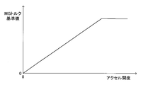
- the “MG torque reference value” is determined based on the map shown in FIG. 2 and the current accelerator opening.
- the MG torque reference value is determined to be larger as the accelerator opening is larger.
- the characteristic of the MG torque reference value with respect to the accelerator opening can change according to various states other than the accelerator opening (for example, distribution of EG torque and MG torque).
- the “MG torque limit value” is determined based on the map shown in FIG. 3 and the current clutch return stroke.
- the MG torque limit value is defined using the meet start point and the release start point.
- the meet start point is the clutch return stroke corresponding to the timing at which C / T shifts from the fully disconnected state to the semi-joined state
- the release start point is C / T from the fully connected state to the semi-joined state. This is a clutch return stroke corresponding to the transition timing.
- the MG torque limit value is within the range where the clutch return stroke is from “0” to “meet start point” (ie, the range corresponding to the C / T completely divided state; see “range a” in FIG. 3).
- the MG torque limit value is The "maximum value” is maintained, and the clutch return stroke is between the "meet start point” and the “release start point” (that is, a range corresponding to the C / T semi-joined state. See “range b” in FIG.
- the MG torque limit value increases from “0” as the clutch return stroke moves from the “meet start point” toward the “release start point”.
- the “maximum value” of the MG torque limit value can be set to a value equal to the current “MG torque reference value”, for example.
- the maps shown in FIGS. 2 and 3 are stored in a predetermined area of the memory in the ECU so as to be updatable.
- the magnitude of the MG torque is normally set to the smaller one of the determined “MG torque reference value” and “MG torque limit value” (hereinafter referred to as “MG torque final reference value”). Adjusted. Note that, when the shift position of the shift lever SL is neutral, the magnitude of the MG torque is maintained at “0”.
- the magnitude of the MG torque is normally determined based on the accelerator opening within the range not exceeding the “MG torque limit value” determined based on the clutch return stroke.
- the driving feeling using the MG torque of the HV-MT vehicle uses the EG torque of the “normal MT vehicle”. It can be closer to the driving feeling.
- a normal MT vehicle refers to a vehicle that has been widely known in the past and includes a manual transmission and a friction clutch, and is mounted only with an internal combustion engine as a power source.
- the accelerator pedal AP, the clutch pedal CP, and the shift lever SL work together to change the shift position from “second gear” to “neutral” due to the driver no longer requesting driving force. It is operated while.
- the operation of the clutch pedal CP is started at the time t1, and the clutch return stroke shifts from the range c to the range b at the time t2 (C / T is in the fully engaged state).
- the clutch return stroke shifts from the range b to the range a at time t3 (C / T shifts from the semi-bonded state to the fully disconnected state), and after time t3, C / T is It is maintained in a completely divided state.
- the accelerator opening starts decreasing toward “0” at time t2, and the accelerator opening is maintained at “0” from time t3.
- the MG torque starts to decrease toward “0” at time t2, and is maintained at “0” from time t3.
- the remaining battery charge SOC is already less than the threshold value TH after time t3.
- the threshold value TH corresponds to a lower limit value of the remaining battery level required for stably rotating the M / G.
- This device is based on the determination that the shift position is “neutral”, C / T is in the joined state, the accelerator opening is “0”, and the remaining battery charge SOC is less than the threshold value TH.
- the charging condition is satisfied.
- the device charges the battery BAT using the EG torque. Specifically, EG torque is used to drive M / G as a generator, and battery BAT is charged using electrical energy obtained by M / G power generation. The charging of the battery BAT is continued until C / T is returned to the completely divided state.
- the charging condition is satisfied at time t4. Therefore, after time t4, the battery BAT is charged by driving the M / G as a generator using the EG torque.
- E / G is stopped before time t4. Therefore, since EG torque is generated after time t4, E / G is started at time t4. The E / G is started using a starter motor (not shown). As a result, the remaining battery charge SOC increases after time t4.
- the friction clutch C / T is in the engaged state and the shift position is in the neutral position (that is, the power between the output shaft of the M / G and the output shaft of the M / T).
- the M / G is driven as a generator using the EG torque. Accordingly, a part of the EG torque is not transmitted to the drive wheels of the vehicle, and therefore a part of the EG torque is not consumed for driving the vehicle. Therefore, the M / G as a generator can be efficiently rotated using the EG torque. As a result, electric energy for battery charging can be generated efficiently. That is, regardless of whether the vehicle is running or stopped, the battery BAT can be efficiently charged using the EG torque when the driver does not require driving force.
- the present invention is not limited to the above embodiment, and various modifications can be employed within the scope of the present invention.
- the friction clutch C / T is in the engaged state and the shift position is in the neutral state, and the M / G is driven as a generator using the EG torque to charge the battery. Of electrical energy is generated.
- M / G cannot be driven using EG torque.
- the alternator ALT may be driven using EG torque instead of M / G, and the battery BAT may be charged using electric energy obtained by the power generation of the alternator ALT.
- the charging condition is “determination that the shift position is neutral, C / T is in the joined state, the accelerator opening is“ 0 ”, and the remaining battery charge SOC is less than the threshold TH.
- the accelerator opening is“ 0 ”
- the remaining battery SOC is less than the threshold TH
- the charging condition is satisfied when the E / G is stopped (see time t4) is shown.
- the charging condition is satisfied when the E / G is operating. It can also happen.
- the operation of the E / G can be continued after the charging condition is satisfied, and the driving of the M / G as a generator can be started immediately by using the already generated EG torque.
- charging of the battery BAT is started at the transition point from the C / T completely divided state to the semi-junction state (see time t4 in FIG. 4).
- the battery BAT has been charged at the time of transition from the semi-junction state of C / T to the fully-junction state, but is terminated at the time of transition to the split state (see time t5 in FIG. 4). May be terminated at the time of transition from the fully joined state to the semi-joined state (see time t5 in FIG. 4).
- the determination that “C / T is in the engaged state” is made based on the clutch return stroke (the detection result of the clutch operation amount sensor S1). May be made based on the determination that “the rotational speed of the output shaft of the engine E / G matches the rotational speed of the input shaft of the manual transmission M / T”.
- each shift operation of the shift lever corresponding to a plurality of shift speeds (1st to 5th speed, reverse in FIG. 5 and FIG. 6) selects the shift lever position.
- shift operation operation in the vehicle front-rear direction
- shift operation operation in the vehicle front-rear direction
- the determination that “the shift position is in the neutral position” indicates that the shift lever movement amount (select stroke) in the select operation exceeds a predetermined amount (eg, gate width) as shown in FIGS. Can be made on the basis of that.
- a predetermined amount eg, gate width
- the position in the shift operation direction of the shift lever in the select operation is set to “N”.
- the position of the shift lever in the shift operation direction during the select operation means, for example, the position of the shift lever in the shift operation direction when the shift lever movement amount exceeds a predetermined amount, or the position of the shift lever during the select operation. The average value of the transition of the position in the shift operation direction.
- an area where the position of the shift lever in the shift operation direction is “N ⁇ ⁇ ” is set as an “N area”. Then, based on the fact that the position of the shift lever in the shift operation direction is within the range of “N region”, it can be determined that “the shift position is in neutral”.
- the “N region” may be set based on a range of fluctuation (maximum / minimum) of the position of the shift lever in the shift operation direction during the select operation.
- the determination that “the shift position is in the neutral position” is made by determining the ratio (speed reduction ratio) of the rotational speed of the input shaft to the rotational speed of the output shaft of the manual transmission M / T. This may be based on the fact that none of the reduction ratios of 1st to 5th gears and reverse gears).
Abstract
この動力伝達制御装置は、動力源として内燃機関(EG)とモータ(MG)とを備えたハイブリッド車両に適用され、手動変速機と、摩擦クラッチとを備える。シフト位置が「ニュートラル」にあり、摩擦クラッチが接合状態にあり、アクセル開度が「0」であり、バッテリ残量SOCが閾値TH未満である場合に充電条件が成立する。充電条件が成立すると、EGトルクを利用したバッテリの充電が行われる。具体的には、EGトルクを利用してMGが発電機として駆動され、MGの発電により得られた電気エネルギを利用してバッテリが充電される。これにより、HV-MT車について、内燃機関トルクを利用して、電動機に電気エネルギを供給するためのバッテリを効率良く充電することができる。
Description
本発明は、車両の動力伝達制御装置に関し、特に、動力源として内燃機関と電動機とを備えた車両に適用され、摩擦クラッチを備えたものに係わる。
従来より、動力源として内燃機関と電動機(電動モータ、電動発電機)とを備えた所謂ハイブリッド車両が広く知られている(例えば、特開2000-224710号公報を参照)。近年、ハイブリッド車両であって、且つ手動変速機と摩擦クラッチとを備えた車両(以下、「HV-MT車」と呼ぶ)が開発されてきている。ここにいう「手動変速機」とは、運転者により操作されるシフトレバーのシフト位置に応じて複数の変速段のうちの1つが選択されるトルクコンバータを備えない変速機(所謂、マニュアルトランスミッション、MT)である。また、ここにいう「摩擦クラッチ」とは、内燃機関の出力軸と手動変速機の入力軸との間に介装されて、運転者により操作されるクラッチペダルの操作量に応じて摩擦プレートの接合状態が変化するクラッチである。以下、内燃機関の出力軸のトルクを「内燃機関トルク」と呼び、電動機の出力軸のトルクを「電動機トルク」と呼ぶ。
HV-MT車では、電動機の出力軸が、内燃機関の出力軸、変速機の入力軸、及び変速機の出力軸の何れかに接続される構成が採用され得る。以下、電動機の出力軸が変速機の入力軸に接続される構成について考察する。
HV-MT車では、電動機に電気エネルギを供給するためのバッテリの残量(蓄積されている(化学)エネルギの量)が少なくなった場合、バッテリを充電する必要がある。バッテリを充電するためには、何らかの発電手段を利用してバッテリ充電用の電気エネルギを発生する必要がある。
ここで、上述のように電動機の出力軸が変速機の入力軸に接続される構成では、摩擦クラッチが接合状態にある場合、内燃機関トルクが摩擦クラッチを介して電動機の出力軸に伝達され得る。換言すれば、内燃機関トルクを利用して電動機を発電機として回転駆動することによって、バッテリ充電用の電気エネルギを発生することができる。
他方、摩擦クラッチが接合状態にある場合であって、且つ、変速機の変速段が走行用の変速段に選択されている場合(即ち、電動機の出力軸と変速機の出力軸との間で動力伝達系統が実現されている場合)、内燃機関トルクの一部が車両の駆動輪に伝達されて、車両の駆動のために消費されてしまう。この場合、内燃機関トルクを利用して発電機としての電動機を効率良く回転駆動することができず、従って、バッテリ充電用の電気エネルギを効率良く発生することができない。
本発明は、上述の問題に対処するためになされたものであり、その目的は、HV-MT車を対象とする動力伝達制御装置であって、内燃機関トルクを利用して、電動機に電気エネルギを供給するためのバッテリを効率良く充電することができるものを提供することにある。
本発明に係る車両の動力伝達制御装置は、動力源として内燃機関と電動機とを備えた車両に適用される。この動力伝達制御装置は、変速機と、摩擦クラッチと、制御手段とを備える。
変速機は、運転者により操作されるシフト操作部材のシフト位置に応じて複数の変速段のうちの1つが選択されるトルクコンバータを備えない手動変速機である。前記変速機は、前記内燃機関の出力軸から動力が入力される入力軸と前記車両の駆動輪へ動力を出力する出力軸とを備える。前記変速機の入力軸には、前記電動機の出力軸が接続される。
摩擦クラッチは、前記内燃機関の出力軸と前記変速機の入力軸との間に介装されて、運転者により操作されるクラッチ操作部材の操作に応じて、動力が伝達される状態である接合状態と動力が伝達されない状態である分断状態とを選択的に実現する。より具体的には、前記接合状態として、滑りを伴わずに動力が伝達される完全接合状態と、滑りを伴いながら動力が伝達される半接合状態とが存在する。運転者によるクラッチ操作部材の操作がなされていない場合には、前記摩擦クラッチは完全接合状態を実現する。
制御手段は、前記内燃機関の出力軸の駆動トルク(内燃機関トルク)、及び前記電動機の出力軸の駆動トルク(電動機トルク)を制御する。
この動力伝達制御装置の特徴は、前記制御手段が、充電条件の成立に基づいて、前記内燃機関トルクを利用して前記電動機を発電機として駆動し、前記電動機の発電により得られた電気エネルギを利用して前記電動機に電気エネルギを供給するためのバッテリを充電するように構成されたことにある。
ここで、前記充電条件には、前記検出されたシフト位置が前記電動機の出力軸と前記変速機の出力軸との間で動力伝達系統が実現されない状態に対応する位置である「駆動力非要求位置」にあると判定されたこと、及び、前記検出されたクラッチ操作部材の操作量に基づいて前記摩擦クラッチが前記接合状態(即ち、完全接合状態又は半接合状態)にあると判定されたこと、が含まれる。「駆動力非要求位置」は、運転者が駆動力を要求しない状態に対応するシフト位置であるということができる。典型的には、「駆動力非要求位置」は、前記変速機の入力軸・出力軸間で動力伝達系統が実現されない状態に対応する。この場合、「駆動力非要求位置」は、例えば、ニュートラル(N)位置である。
上記構成によれば、摩擦クラッチが接合状態にあり、且つ、電動機の出力軸と変速機の出力軸との間で動力伝達系統が実現されない状態で、内燃機関トルクを利用して電動機が発電機として駆動され得る。従って、内燃機関トルクの一部が車両の駆動輪に伝達されないので、内燃機関トルクの一部が車両の駆動のために消費されない。よって、内燃機関トルクを利用して発電機としての電動機が効率良く回転駆動され得、バッテリ充電用の電気エネルギが効率良く発生され得る。即ち、(車両が走行中であろうと停止中であろうと)運転者が駆動力を要求しない状態において、内燃機関トルクを利用して、電動機に電気エネルギを供給するためのバッテリを効率良く充電することができる。
前記充電条件には、バッテリに蓄積されているエネルギの量が所定値未満であると判定されたことが含まれることが好適である。これにより、バッテリに蓄積されているエネルギの量が少なくなったときにバッテリが充電されることが確実に担保される。
加えて、前記充電条件には、運転者により操作される前記車両を加速させるための加速操作部材の操作がなされていないと判定されたことが含まれることが好適である。これにより、「運転者が駆動力を要求しない状態にてバッテリが充電される」ことがより一層確実に担保され得る。
前記充電条件が成立したときに内燃機関が稼働している場合、既に発生している内燃機関トルクを利用して電動機の駆動を直ちに開始できる。一方、前記充電条件が成立したときに内燃機関が停止している場合、前記内燃機関を始動して内燃機関トルクを発生する必要がある。この場合、内燃機関の始動(即ち、内燃機関の出力軸の回転駆動)は、スタータモータを利用して行われ得る。
ところで、シフト位置が「駆動力非要求位置」にある場合であっても、摩擦クラッチが分断状態にあるときには、内燃機関トルクを利用して電動機を回転駆動することができない。この場合、電動機の代わりに「内燃機関トルクによって駆動されるオルタネータ」を内燃機関トルクを利用して駆動し、前記オルタネータの発電により得られた電気エネルギを利用して前記バッテリを充電するように構成され得る。
以下、本発明による車両の動力伝達制御装置の実施形態について図面を参照しつつ説明する。
(構成)
図1は、本発明の実施形態に係る動力伝達制御装置(以下、「本装置」と称呼する。)を搭載した車両の概略構成を示している。この車両は、動力源としてエンジンE/GとモータジェネレータM/Gとを備えたハイブリッド車両であり、且つ、トルクコンバータを備えない手動変速機M/Tと摩擦クラッチC/Tとを備える。即ち、この車両は、上述したHV-MT車である。
図1は、本発明の実施形態に係る動力伝達制御装置(以下、「本装置」と称呼する。)を搭載した車両の概略構成を示している。この車両は、動力源としてエンジンE/GとモータジェネレータM/Gとを備えたハイブリッド車両であり、且つ、トルクコンバータを備えない手動変速機M/Tと摩擦クラッチC/Tとを備える。即ち、この車両は、上述したHV-MT車である。
エンジンE/Gは、周知の内燃機関であり、例えば、ガソリンを燃料として使用するガソリンエンジン、軽油を燃料として使用するディーゼルエンジンである。
手動変速機M/Tは、運転者により操作されるシフトレバーSLのシフト位置に応じて複数の変速段のうちの1つが選択されるトルクコンバータを備えない変速機(所謂、マニュアルトランスミッション)である。M/Tは、E/Gの出力軸から動力が入力される入力軸と、車両の駆動輪へ動力を出力する出力軸とを備える。
M/Tは、変速段として、例えば、前進用の5つの変速段(1速~5速)、後進用の1つの変速段(リバース)、並びに、「ニュートラル」を備えている。前進用及び後進用の変速段が選択されている場合、M/Tの入力軸・出力軸間で動力伝達系統が実現される。一方、「ニュートラル」が選択されている場合、M/Tの入力軸・出力軸間で動力伝達系統が実現されない。
M/Tの変速段は、シフトレバーSLとM/T内部のスリーブ(図示せず)とを機械的に連結するリンク機構等を利用してシフトレバーSLのシフト位置に応じて機械的に選択・変更されてもよいし、シフトレバーSLのシフト位置を検出するセンサ(後述するセンサS2)の検出結果に基づいて作動するアクチュエータの駆動力を利用して電気的に(所謂バイ・ワイヤ方式で)選択・変更されてもよい。
摩擦クラッチC/Tは、E/Gの出力軸とM/Tの入力軸との間に介装されている。C/Tは、運転者により操作されるクラッチペダルCPの操作量(踏み込み量)に応じて摩擦プレートの接合状態(より具体的には、E/Gの出力軸と一体回転するフライホイールに対する、M/Tの入力軸と一体回転する摩擦プレートの軸方向位置)が変化する周知のクラッチである。
C/Tの状態としては、完全接合状態、半接合状態、及び、完全分断状態が存在する。完全接合状態とは、滑りを伴わずに動力を伝達する状態を指す。半接合状態とは、滑りを伴いながら動力を伝達する状態を指す。完全接合状態及び半接合状態は、「接合状態」に対応する。完全分断状態とは、動力を伝達しない状態を指す。以下、クラッチペダルCPが最も深く踏み込まれた状態からのクラッチペダルCPの戻し方向の操作量を「クラッチ戻しストローク」と呼ぶ。
クラッチ戻しストロークは、クラッチペダルCPが最も深く踏み込まれた状態にて「0」となり、クラッチペダルCPが開放されている(操作されていない)状態にて最大となる。クラッチ戻しストロークが「0」から増大するにつれて、C/Tは、完全分断状態から半接合状態を経て完全接合状態へと移行する。
C/Tの接合状態(摩擦プレートの軸方向位置)は、クラッチペダルCPとC/T(摩擦プレート)とを機械的に連結するリンク機構等を利用してCPの操作量に応じて機械的に調整されてもよいし、CPの操作量を検出するセンサ(後述するセンサS1)の検出結果に基づいて作動するアクチュエータの駆動力を利用して電気的に(所謂バイ・ワイヤ方式で)調整されてもよい。
モータジェネレータM/Gは、周知の構成(例えば、交流同期モータ)の1つを有していて、例えば、ロータ(図示せず)がM/Gの出力軸と一体回転するようになっている。M/Gの出力軸は、周知のギヤ列等を介してM/Tの入力軸に動力伝達可能に接続されている。以下、E/Gの出力軸のトルクを「EGトルク」と呼び、M/Gの出力軸のトルクを「MGトルク」と呼ぶ。
M/Gは、バッテリBATから供給される電気エネルギを利用して回転駆動トルク(=MGトルク)を発生する。このMGトルクの大きさは、インバータINVを制御することによって調整され得る。MGトルクは、M/Tを介して車両の駆動輪に伝達される。一方、M/Gは、外部から回転駆動されることによって発電機として機能し、M/Gの発電により得られた電気エネルギを利用してバッテリBATが充電され得る。バッテリBATの充電速度(単位時間あたりの充電量)は、インバータINVを制御することによって調整され得る。
なお、バッテリBATの充電は、EGトルクによって回転駆動されるオルタネータALTの発電により得られた電気エネルギを利用してもなされ得る。この場合も、バッテリBATの充電速度(単位時間あたりの充電量)は、インバータINVを制御することによって調整され得る。
本装置は、クラッチペダルCPのクラッチ戻しストロークを検出するクラッチ操作量センサS1と、シフトレバーSLの位置を検出するシフト位置センサS2と、アクセルペダルAPの操作量(アクセル開度)を検出するアクセル操作量センサS3と、ブレーキペダルBPの操作量(踏力、操作の有無等)を検出するブレーキ操作量センサS4と、車輪の速度を検出する車輪速度センサS5と、を備えている。
更に、本装置は、電子制御ユニットECUを備えている。ECUは、上述のセンサS1~S5、並びにその他のセンサ等からの情報等に基づいて、E/Gの燃料噴射量(スロットル弁の開度)を制御することによりEGトルクを制御し、インバータINVを制御することによりMGトルクの大きさ、並びに、バッテリBATの充電速度を制御する。
EGトルクとMGトルクとの配分は、上述のセンサS1~S5、並びにその他のセンサ等からの情報等に基づいて調整される。EGトルク及びMGトルクの大きさはそれぞれ、主としてアクセル開度に基づいて調整される。特に、MGトルクは、本例では、以下のように調整される。
即ち、先ず、図2に示すマップと、現在のアクセル開度とに基づいて、「MGトルク基準値」が決定される。MGトルク基準値は、アクセル開度が大きいほど、より大きい値に決定される。MGトルク基準値のアクセル開度に対する特性は、アクセル開度以外の種々の状態(例えば、EGトルクとMGトルクとの配分)に応じて変化し得る。
また、図3に示すマップと、現在のクラッチ戻しストロークとに基づいて、「MGトルク制限値」が決定される。MGトルク制限値は、ミート開始点とリリース開始点とを利用して規定される。ミート開始点とは、C/Tが完全分断状態から半接合状態へと移行するタイミングに対応するクラッチ戻しストロークであり、リリース開始点とは、C/Tが完全接合状態から半接合状態へと移行するタイミングに対応するクラッチ戻しストロークである。
この例では、クラッチ戻しストロークが「0」から「ミート開始点」の範囲(即ち、C/Tの完全分断状態に対応する範囲。図3の「範囲a」を参照)ではMGトルク制限値が「0」に維持され、クラッチ戻しストロークが「リリース開始点」より大きい範囲(即ち、C/Tの完全接合状態に対応する範囲。図3の「範囲c」を参照)ではMGトルク制限値が「最大値」に維持され、クラッチ戻しストロークが「ミート開始点」と「リリース開始点」との間(即ち、C/Tの半接合状態に対応する範囲。図3の「範囲b」を参照)ではクラッチ戻しストロークが「ミート開始点」から「リリース開始点」に向けて移動するにつれてMGトルク制限値が「0」から増大する。ここで、MGトルク制限値の上記「最大値」とは、例えば、現在の上記「MGトルク基準値」と等しい値に設定され得る。なお、図2及び図3に示すマップは、ECU内のメモリの所定領域に更新可能に記憶されている。
そして、MGトルクの大きさは、通常、前記決定された「MGトルク基準値」と「MGトルク制限値」とのうちで小さい方の値(以下、「MGトルク最終基準値」と呼ぶ)に調整される。なお、シフトレバーSLのシフト位置がニュートラルの場合にはMGトルクの大きさは「0」に維持される。
以上のように、MGトルクの大きさは、通常、クラッチ戻しストロークに基づいて決定される「MGトルク制限値」を超えない範囲内において、アクセル開度等に基づいて決定される「MGトルク基準値」に基づく値(=MGトルク最終基準値)に調整される。このようにMGトルクの大きさをMGトルク最終基準値に一致するように調整することにより、HV-MT車のMGトルクを利用した運転フィーリングを、「通常MT車」のEGトルクを利用した運転フィーリングに近づけることができる。通常MT車とは、手動変速機と摩擦クラッチとを備え且つ動力源として内燃機関のみを搭載した従前から広く知られた車両を指す。
(EGトルクを利用したバッテリの充電)
図1に示したHV-MT車では、バッテリBATの残量SOC(蓄積されている(化学)エネルギの量、State of Charge)が少なくなった場合、バッテリBATを充電する必要がある。本装置では、M/Gの出力軸がM/Tの入力軸に接続されている。この構成では、C/Tが接合状態にある場合、EGトルクがC/Tを介してM/Gの出力軸に伝達される。
図1に示したHV-MT車では、バッテリBATの残量SOC(蓄積されている(化学)エネルギの量、State of Charge)が少なくなった場合、バッテリBATを充電する必要がある。本装置では、M/Gの出力軸がM/Tの入力軸に接続されている。この構成では、C/Tが接合状態にある場合、EGトルクがC/Tを介してM/Gの出力軸に伝達される。
即ち、本装置では、EGトルクを利用してM/Gを発電機として回転駆動することによって、バッテリ充電用の電気エネルギを発生することができる。係る知見に基づき、本装置は、バッテリBATの充電を行う。
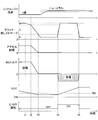
以下、このことについて、図4を参照しながら説明する。図4に示す例では、時刻t1以前にて、車両が、E/Gが停止した状態で、バッテリBATに蓄積されたエネルギを消費しながらMGトルクのみを利用して「2速」で走行している。時刻t1以前では、MGトルク>0、EGトルク=0、アクセル開度>0であり、C/Tは完全接合状態にある。MGトルクを利用した走行に起因して、バッテリ残量SOCが徐々に低下している。
時刻t1以降、運転者が駆動力を要求しなくなることに起因して、シフト位置を「2速」から「ニュートラル」に変更するため、アクセルペダルAP、クラッチペダルCP、及びシフトレバーSLが連携しながら操作される。
この例では、クラッチペダルCPの操作に着目すると、時刻t1にてクラッチペダルCPの操作が開始され、時刻t2にてクラッチ戻しストロークが範囲cから範囲bに移行し(C/Tが完全接合状態から半接合状態に移行し)、時刻t3にてクラッチ戻しストロークが範囲bから範囲aに移行し(C/Tが半接合状態から完全分断状態に移行し)、時刻t3以降、C/Tが完全分断状態に維持されている。
アクセルペダルAPの操作に着目すると、時刻t2にてアクセル開度が「0」に向けて減少を開始し、時刻t3からアクセル開度が「0」に維持されている。これに伴い、MGトルクも、時刻t2にて「0」に向けて減少を開始し、時刻t3から「0」に維持されている。この結果、バッテリ残量SOCは、時刻t3以降では既に閾値TH未満となっている。閾値THは、M/Gを安定して回転駆動するために必要とされるバッテリ残量の下限値等に相当する。
シフトレバーSLの操作に着目すると、「2速」から「ニュートラル」へのシフト操作は、C/Tが完全分断状態にある時刻t3以降に実行されている。
この例では、「2速」から「ニュートラル」へのシフト操作の完了後、クラッチ戻しストロークが範囲aから範囲bを経て範囲cに戻される。この結果、時刻t4にてC/Tが完全分断状態から接合状態(具体的には、半接合状態)に移行している。即ち、時刻t4にて、シフト位置が「ニュートラル」にあり、C/Tが接合状態にあり、アクセル開度が「0」であり、バッテリ残量SOCが閾値TH未満となっている。
本装置は、シフト位置が「ニュートラル」にあり、C/Tが接合状態にあり、アクセル開度が「0」であり、バッテリ残量SOCが閾値TH未満であると判定されたことに基づいて、充電条件が成立する。本装置は、充電条件が成立すると、EGトルクを利用したバッテリBATの充電を行う。具体的には、EGトルクを利用してM/Gを発電機として駆動し、M/Gの発電により得られた電気エネルギを利用してバッテリBATが充電される。このバッテリBATの充電は、C/Tが完全分断状態に戻されるまで継続される。
図4に示す例では、時刻t4にて充電条件が成立する。従って、時刻t4以降、EGトルクを利用してM/Gを発電機として駆動することによってバッテリBATの充電が行われる。図4に示す例では、時刻t4以前にてE/Gが停止している。従って、時刻t4以降においてEGトルクを発生するため、時刻t4にてE/Gが始動される。E/Gの始動は、スタータモータ(図示せず)を利用して行われる。この結果、時刻t4以降、バッテリ残量SOCが増大していく。
図4に示す例では、バッテリ残量SOCが閾値THを超えた後、クラッチ戻しストロークが範囲cから範囲bを経て範囲aに再び戻される。この結果、時刻t5にてC/Tが半接合状態から完全分断状態に移行している。従って、時刻t5にて、バッテリBATの充電が終了する。これに伴い、E/Gが再び停止される。
このように、本装置によれば、摩擦クラッチC/Tが接合状態にあり、且つ、シフト位置がニュートラルにある(即ち、M/Gの出力軸とM/Tの出力軸との間で動力伝達系統が実現されない)状態で、EGトルクを利用してM/Gが発電機として駆動される。従って、EGトルクの一部が車両の駆動輪に伝達されないので、EGトルクの一部が車両の駆動のために消費されない。よって、EGトルクを利用して発電機としてのM/Gが効率良く回転駆動され得る。この結果、バッテリ充電用の電気エネルギが効率良く発生され得る。即ち、車両が走行中であろうと停止中であろうと、運転者が駆動力を要求しない状態において、EGトルクを利用してバッテリBATを効率良く充電することができる。
本発明は上記実施形態に限定されることはなく、本発明の範囲内において種々の変形例を採用することができる。例えば、上記実施形態では、摩擦クラッチC/Tが接合状態にあり、且つ、シフト位置がニュートラルにある状態で、EGトルクを利用してM/Gが発電機として駆動されることによってバッテリ充電用の電気エネルギが発生される。これに対し、C/Tが分断状態にある場合にはEGトルクを利用してM/Gが駆動され得ない。この場合、M/Gの代わりにオルタネータALTをEGトルクを利用して駆動し、オルタネータALTの発電により得られた電気エネルギを利用してバッテリBATを充電するように構成され得る。
また、上記実施形態では、充電条件として、「シフト位置がニュートラルにあり、C/Tが接合状態にあり、アクセル開度が「0」であり、バッテリ残量SOCが閾値TH未満であると判定されたこと」が採用されているが、これらのうち、「アクセル開度が「0」であること」及び「バッテリ残量SOCが閾値TH未満であること」の何れか一方又は両方が省略されてもよい。
また、上述した図4に示す例では、E/Gが停止した状態で充電条件が成立する場合(時刻t4を参照)が示されているが、E/Gが稼働した状態で充電条件が成立する場合も発生し得る。この場合、充電条件の成立後にE/Gの稼働を継続するとともに、既に発生しているEGトルクを利用して発電機としてのM/Gの駆動を直ちに開始できる。
また、上記実施形態では、バッテリBATの充電が、C/Tの完全分断状態から半接合状態への移行時点(図4の時刻t4を参照)で開始され、C/Tの半接合状態から完全分断状態への移行時点(図4の時刻t5を参照)で終了しているが、バッテリBATの充電が、C/Tの半接合状態から完全接合状態への移行時点で開始され、C/Tの完全接合状態から半接合状態への移行時点(図4の時刻t5を参照)で終了してもよい。
また、上記実施形態では、「C/Tが接合状態にある」との判定が、クラッチ戻しストローク(クラッチ操作量センサS1の検出結果)に基づいてなされているが、「C/Tが接合状態にある」との判定が、「エンジンE/Gの出力軸の回転速度と手動変速機M/Tの入力軸の回転速度とが一致している」との判定に基づいてなされてもよい。
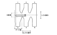
以下、「シフト位置がニュートラルにある」との判定を行う方法について付言する。図5及び図6に示すように、複数の変速段(図5及び図6では、1速~5速、リバース)に対応するシフトレバーのそれぞれのシフト操作が、シフトレバーの位置を、セレクト操作(車両左右方向の操作)によって対応するセレクト位置に移動し、その後、シフト操作(車両前後方向の操作)によって対応するセレクト位置から対応するシフト位置に移動することにより達成される場合(即ち、シフトパターンとして所謂「Hパターン」が採用される場合)を想定する。
この場合、「シフト位置がニュートラルにある」との判定は、図5及び図6に示すように、セレクト操作におけるシフトレバーの移動量(セレクトストローク)が所定量(例えば、ゲート幅)を超えたことに基づいてなされ得る。具体的には、先ず、セレクト操作におけるシフトレバーの移動量が所定量を超えたとき、セレクト操作時におけるシフトレバーのシフト操作方向の位置が「N」と設定される。「セレクト操作時におけるシフトレバーのシフト操作方向の位置」とは、例えば、シフトレバーの移動量が所定量を超えた時点でのシフトレバーのシフト操作方向の位置そのもの、セレクト操作中におけるシフトレバーのシフト操作方向の位置の推移の平均値等である。次いで、シフトレバーのシフト操作方向の位置が「N±α」となる領域が「N領域」と設定される。そして、シフトレバーのシフト操作方向の位置が「N領域」の範囲内にあることに基づいて、「シフト位置がニュートラルにある」との判定がなされ得る。なお、「N領域」は、セレクト操作中におけるシフトレバーのシフト操作方向の位置の変動範囲(最大・最小)に基づいて設定されてもよい。
或いは、「シフト位置がニュートラルにある」との判定は、手動変速機M/Tの出力軸の回転速度に対する入力軸の回転速度の割合(減速比)が既知の複数の変速段の減速比(1速~5速、リバースのそれぞれの減速比)の何れとも一致しないことに基づいてなされてもよい。
Claims (8)
- 動力源として内燃機関と電動機とを備えた車両に適用され、
前記内燃機関の出力軸から動力が入力される入力軸と前記車両の駆動輪へ動力を出力する出力軸とを備え、運転者により操作されるシフト操作部材のシフト位置に応じて複数の変速段のうちの1つが選択される変速機であって、前記入力軸に前記電動機の出力軸が接続された変速機と、
前記内燃機関の出力軸と前記変速機の入力軸との間に介装されて、運転者により操作されるクラッチ操作部材の操作に応じて、動力が伝達される状態である接合状態と動力が伝達されない状態である分断状態とを選択的に実現する摩擦クラッチと、
前記クラッチ操作部材の操作量を検出する第1検出手段と、
前記シフト操作部材のシフト位置を検出する第2検出手段と、
前記内燃機関の出力軸の駆動トルクである内燃機関トルク、及び前記電動機の出力軸の駆動トルクである電動機トルクを制御する制御手段と、
を備えた車両の動力伝達制御装置であって、
前記制御手段は、
前記検出されたシフト位置が前記電動機の出力軸と前記変速機の出力軸との間で動力伝達系統が実現されない状態に対応する位置である駆動力非要求位置にあると判定されたこと、及び、前記検出されたクラッチ操作部材の操作量に基づいて前記摩擦クラッチが前記接合状態にあると判定されたこと、を含む充電条件の成立に基づいて、前記内燃機関トルクを利用して前記電動機を発電機として駆動し、前記電動機の発電により得られた電気エネルギを利用して前記電動機に電気エネルギを供給するためのバッテリを充電するように構成された、車両の動力伝達制御装置。 - 請求項1に記載の車両の動力伝達制御装置において、
前記充電条件は、
前記バッテリに蓄積されているエネルギの量が所定値未満であると判定されたことを含む、車両の動力伝達制御装置。 - 請求項2に記載の車両の動力伝達制御装置において、
前記充電条件は、運転者により操作される前記車両を加速させるための加速操作部材の操作がなされていないと判定されたことを含む、車両の動力伝達制御装置。 - 請求項1乃至請求項3の何れか一項に記載の車両の動力伝達制御装置において、
前記制御手段は、
前記充電条件が成立したときに前記内燃機関が停止している場合、前記内燃機関を始動して前記内燃機関トルクを発生するように構成された、車両の動力伝達制御装置。 - 請求項1乃至請求項4の何れか一項に記載の車両の動力伝達制御装置において、
前記駆動力非要求位置はニュートラル位置である、車両の動力伝達制御装置。 - 請求項5に記載の車両の動力伝達制御装置において、
前記複数の変速段に対応する前記シフト操作部材のそれぞれのシフト操作が、前記シフト操作部材の位置を、前記車両の左右方向の操作であるセレクト操作によって対応するセレクト位置に移動し、その後、前記車両の前後方向の操作であるシフト操作によって前記対応するセレクト位置から対応するシフト位置に移動することにより達成されるように構成され、
前記制御手段は、
前記セレクト操作において前記シフト操作部材の移動量が所定量を超えたことに基づいて、前記検出されたシフト位置が前記ニュートラル位置にあると判定するように構成された、車両の動力伝達制御装置。 - 請求項5に記載の車両の動力伝達制御装置において、
前記複数の変速段に対応する前記シフト操作部材のそれぞれのシフト操作が、前記シフト操作部材の位置を、前記車両の左右方向の操作であるセレクト操作によって対応するセレクト位置に移動し、その後、前記車両の前後方向の操作であるシフト操作によって前記対応するセレクト位置から対応するシフト位置に移動することにより達成されるように構成され、
前記制御手段は、
前記変速機の出力軸の回転速度に対する前記変速機の入力軸の回転速度の割合である減速比が既知の前記複数の変速段の減速比の何れとも一致しないことに基づいて、前記検出されたシフト位置が前記ニュートラル位置にあると判定するように構成された、車両の動力伝達制御装置。 - 請求項1乃至請求項7の何れか一項に記載の車両の動力伝達制御装置において、
前記制御手段は、
前記検出されたシフト位置が前記駆動力非要求位置にあると判定されたこと、及び、前記検出されたクラッチ操作部材の操作量に基づいて前記摩擦クラッチが前記分断状態にあると判定されたこと、を含む第2の充電条件の成立に基づいて、前記内燃機関トルクによって駆動されるオルタネータを前記内燃機関トルクを利用して駆動し、前記オルタネータの発電により得られた電気エネルギを利用して前記バッテリを充電するように構成された、車両の動力伝達制御装置。
Priority Applications (3)
| Application Number | Priority Date | Filing Date | Title |
|---|---|---|---|
| CN201280008488.1A CN103429474B (zh) | 2011-02-09 | 2012-02-08 | 车辆的动力传递控制装置 |
| US13/984,376 US9085298B2 (en) | 2011-02-09 | 2012-02-08 | Power transmission control device for vehicle |
| EP12744258.0A EP2674342A4 (en) | 2011-02-09 | 2012-02-08 | Power transmission control device for cars |
Applications Claiming Priority (2)
| Application Number | Priority Date | Filing Date | Title |
|---|---|---|---|
| JP2011025700A JP5521151B2 (ja) | 2011-02-09 | 2011-02-09 | 車両の動力伝達制御装置 |
| JP2011-025700 | 2011-02-09 |
Publications (1)
| Publication Number | Publication Date |
|---|---|
| WO2012108466A1 true WO2012108466A1 (ja) | 2012-08-16 |
Family
ID=46638679
Family Applications (1)
| Application Number | Title | Priority Date | Filing Date |
|---|---|---|---|
| PCT/JP2012/052864 WO2012108466A1 (ja) | 2011-02-09 | 2012-02-08 | 車両の動力伝達制御装置 |
Country Status (5)
| Country | Link |
|---|---|
| US (1) | US9085298B2 (ja) |
| EP (1) | EP2674342A4 (ja) |
| JP (1) | JP5521151B2 (ja) |
| CN (1) | CN103429474B (ja) |
| WO (1) | WO2012108466A1 (ja) |
Families Citing this family (16)
| Publication number | Priority date | Publication date | Assignee | Title |
|---|---|---|---|---|
| GB2447672B (en) | 2007-03-21 | 2011-12-14 | Ford Global Tech Llc | Vehicle manoeuvring aids |
| JP2013103516A (ja) * | 2011-11-10 | 2013-05-30 | Toyota Motor Corp | 車両および車両の制御方法 |
| US9145133B2 (en) * | 2013-11-08 | 2015-09-29 | Ford Global Technologies, Llc | Method and system for selecting an engine operating point for a hybrid vehicle |
| CN103660913B (zh) * | 2013-12-11 | 2016-05-25 | 南京越博动力系统股份有限公司 | 一种单轴并联混合动力客车能量分配方法 |
| US9475479B2 (en) * | 2014-04-29 | 2016-10-25 | Ford Global Technologies, Llc | Electrified vehicle neutral engine start |
| US9493063B2 (en) * | 2014-07-16 | 2016-11-15 | GM Global Technology Operations LLC | Method to allow trickle-charging on a strong hybrid vehicle to balance accessory loads |
| JP2017031034A (ja) * | 2015-08-06 | 2017-02-09 | 信越化学工業株式会社 | SiC単結晶の製造方法 |
| JP6304173B2 (ja) | 2015-08-18 | 2018-04-04 | トヨタ自動車株式会社 | 車両 |
| US10836372B2 (en) * | 2016-08-24 | 2020-11-17 | Ford Global Technologies, Llc | System and method for controlling a hybrid vehicle in park or neutral |
| KR101836289B1 (ko) * | 2016-10-21 | 2018-04-19 | 현대자동차 주식회사 | 친환경 차량용 엔진 클러치 제어 장치 및 방법 |
| US11215244B2 (en) * | 2017-03-22 | 2022-01-04 | Kawasaki Jukogyo Kabushiki Kaisha | Vehicle |
| DE102017110689A1 (de) * | 2017-05-17 | 2018-11-22 | Schaeffler Technologies AG & Co. KG | Verfahren zum Bestimmen eines Fehlers eines Moments einer Brennkraftmaschine in einem Hybridantriebsstrang |
| DE102017214748A1 (de) * | 2017-08-23 | 2019-02-28 | Volkswagen Aktiengesellschaft | Verfahren zum Betreiben eines Fahrerassistenzsystems eines Kraftfahrzeugs sowie Kraftfahrzeug mit einer elektronischen Recheneinrichtung |
| EP3851309B1 (en) * | 2018-09-10 | 2024-04-24 | Nissan Motor Co., Ltd. | Power transmitting device for vehicle |
| DE102019107337A1 (de) * | 2019-03-22 | 2020-09-24 | Schaeffler Technologies AG & Co. KG | Verfahren zur Ermittlung einer Drehmomentübertragungseigenschaft einer Kupplung durch einen ausgewählten Abtriebsdrehzahlgradienten |
| JP7388334B2 (ja) | 2020-10-22 | 2023-11-29 | トヨタ自動車株式会社 | 二次電池の劣化判定装置 |
Citations (7)
| Publication number | Priority date | Publication date | Assignee | Title |
|---|---|---|---|---|
| JPH05222946A (ja) * | 1992-02-14 | 1993-08-31 | Toyota Motor Corp | 過給機付エンジンの制御装置 |
| JP2000224710A (ja) | 1999-01-27 | 2000-08-11 | Mitsubishi Motors Corp | ハイブリッド車 |
| JP2000343965A (ja) * | 1999-06-08 | 2000-12-12 | Nissan Diesel Motor Co Ltd | ハイブリッド車両 |
| JP2001235030A (ja) * | 2000-02-24 | 2001-08-31 | Isuzu Motors Ltd | 変速機のシフトアシスト装置 |
| JP2002089307A (ja) * | 2000-09-14 | 2002-03-27 | Toyota Motor Corp | 可変気筒エンジンの制御装置および車両の制御装置 |
| JP2007030599A (ja) * | 2005-07-25 | 2007-02-08 | Nissan Motor Co Ltd | エンジンの回転速度表示装置 |
| JP2010030329A (ja) * | 2008-07-25 | 2010-02-12 | Nissan Motor Co Ltd | 変速レバーの操作位置検出装置 |
Family Cites Families (7)
| Publication number | Priority date | Publication date | Assignee | Title |
|---|---|---|---|---|
| DE2943519A1 (de) * | 1979-10-27 | 1981-05-07 | Volkswagenwerk Ag | Antrieb fuer ein fahrzeug mit einer brennkraftmaschine und einem elektromotor |
| JP2973796B2 (ja) * | 1993-10-07 | 1999-11-08 | トヨタ自動車株式会社 | ハイブリッド電気自動車の空調制御方法 |
| WO1997045287A1 (fr) * | 1996-05-24 | 1997-12-04 | Hino Jidosha Kogyo Kabushiki Kaisha | Controleur pour batterie de vehicule embarquee |
| JP2004076841A (ja) * | 2002-08-16 | 2004-03-11 | Suzuki Motor Corp | 車両用自動変速制御装置 |
| JP4492585B2 (ja) * | 2006-05-29 | 2010-06-30 | 日産自動車株式会社 | ハイブリッド車両の制御装置及びハイブリッド車両の制御方法。 |
| WO2009090913A1 (ja) * | 2008-01-14 | 2009-07-23 | Toyota Jidosha Kabushiki Kaisha | リチウムイオン二次電池の充電方法、及び、ハイブリッド自動車 |
| GB2466040B (en) * | 2008-12-09 | 2012-12-05 | Ford Global Tech Llc | A method and apparatus for establishing the engagement state of a manual transmission |
-
2011
- 2011-02-09 JP JP2011025700A patent/JP5521151B2/ja not_active Expired - Fee Related
-
2012
- 2012-02-08 US US13/984,376 patent/US9085298B2/en not_active Expired - Fee Related
- 2012-02-08 EP EP12744258.0A patent/EP2674342A4/en not_active Withdrawn
- 2012-02-08 CN CN201280008488.1A patent/CN103429474B/zh not_active Expired - Fee Related
- 2012-02-08 WO PCT/JP2012/052864 patent/WO2012108466A1/ja active Application Filing
Patent Citations (7)
| Publication number | Priority date | Publication date | Assignee | Title |
|---|---|---|---|---|
| JPH05222946A (ja) * | 1992-02-14 | 1993-08-31 | Toyota Motor Corp | 過給機付エンジンの制御装置 |
| JP2000224710A (ja) | 1999-01-27 | 2000-08-11 | Mitsubishi Motors Corp | ハイブリッド車 |
| JP2000343965A (ja) * | 1999-06-08 | 2000-12-12 | Nissan Diesel Motor Co Ltd | ハイブリッド車両 |
| JP2001235030A (ja) * | 2000-02-24 | 2001-08-31 | Isuzu Motors Ltd | 変速機のシフトアシスト装置 |
| JP2002089307A (ja) * | 2000-09-14 | 2002-03-27 | Toyota Motor Corp | 可変気筒エンジンの制御装置および車両の制御装置 |
| JP2007030599A (ja) * | 2005-07-25 | 2007-02-08 | Nissan Motor Co Ltd | エンジンの回転速度表示装置 |
| JP2010030329A (ja) * | 2008-07-25 | 2010-02-12 | Nissan Motor Co Ltd | 変速レバーの操作位置検出装置 |
Also Published As
| Publication number | Publication date |
|---|---|
| JP2012162215A (ja) | 2012-08-30 |
| JP5521151B2 (ja) | 2014-06-11 |
| EP2674342A4 (en) | 2018-04-04 |
| US9085298B2 (en) | 2015-07-21 |
| CN103429474A (zh) | 2013-12-04 |
| CN103429474B (zh) | 2016-01-20 |
| EP2674342A1 (en) | 2013-12-18 |
| US20140011632A1 (en) | 2014-01-09 |
Similar Documents
| Publication | Publication Date | Title |
|---|---|---|
| JP5521151B2 (ja) | 車両の動力伝達制御装置 | |
| US7789177B2 (en) | Control apparatus and control method for drive apparatus of hybrid vehicle | |
| US7498757B2 (en) | Control device for a hybrid electric vehicle | |
| US8540603B2 (en) | Vehicle power transmission control device | |
| JP5367682B2 (ja) | 車両の動力伝達制御装置 | |
| CN103010205B (zh) | 车辆的动力传递控制装置 | |
| US10737682B2 (en) | Drive force control system for hybrid vehicle | |
| WO2013150964A1 (ja) | ハイブリッド電気自動車の制御装置 | |
| JP5422544B2 (ja) | 車両の動力伝達制御装置 | |
| KR20180067984A (ko) | 마일드 하이브리드 차량의 mhsg 제어 방법 및 장치 | |
| JP2018052320A (ja) | ハイブリッド車両システムの制御装置及び制御方法 | |
| JP5821475B2 (ja) | ハイブリッド車両の制御装置 | |
| JP5769956B2 (ja) | 車両の動力伝達制御装置 | |
| JP5715848B2 (ja) | 車両の動力伝達制御装置 | |
| JP5185994B2 (ja) | 車両の動力伝達制御装置 | |
| JP4086077B2 (ja) | 内燃機関の始動制御装置 | |
| JP2004251452A (ja) | ハイブリッド車両の制御装置 | |
| JP5469039B2 (ja) | ハイブリッド車両 | |
| WO2012081280A1 (ja) | 車両の動力伝達制御装置 | |
| JP5650262B2 (ja) | 車両の動力伝達制御装置 | |
| WO2012077382A1 (ja) | 車両の動力伝達制御装置 | |
| JP2012153244A (ja) | 車両の動力伝達制御装置 |
Legal Events
| Date | Code | Title | Description |
|---|---|---|---|
| 121 | Ep: the epo has been informed by wipo that ep was designated in this application |
Ref document number: 12744258 Country of ref document: EP Kind code of ref document: A1 |
|
| NENP | Non-entry into the national phase |
Ref country code: DE |
|
| WWE | Wipo information: entry into national phase |
Ref document number: 2012744258 Country of ref document: EP |
|
| WWE | Wipo information: entry into national phase |
Ref document number: 13984376 Country of ref document: US |