WO2012108466A1 - Dispositif de commande de transmission de puissance pour véhicules - Google Patents
Dispositif de commande de transmission de puissance pour véhicules Download PDFInfo
- Publication number
- WO2012108466A1 WO2012108466A1 PCT/JP2012/052864 JP2012052864W WO2012108466A1 WO 2012108466 A1 WO2012108466 A1 WO 2012108466A1 JP 2012052864 W JP2012052864 W JP 2012052864W WO 2012108466 A1 WO2012108466 A1 WO 2012108466A1
- Authority
- WO
- WIPO (PCT)
- Prior art keywords
- vehicle
- shift
- control device
- power transmission
- torque
- Prior art date
Links
- 230000005540 biological transmission Effects 0.000 title claims abstract description 71
- 238000002485 combustion reaction Methods 0.000 claims abstract description 47
- 230000007935 neutral effect Effects 0.000 claims abstract description 22
- 238000010248 power generation Methods 0.000 claims abstract description 10
- 238000001514 detection method Methods 0.000 claims description 6
- 230000009467 reduction Effects 0.000 claims description 4
- 230000001133 acceleration Effects 0.000 claims description 2
- 230000005611 electricity Effects 0.000 abstract 1
- 239000013256 coordination polymer Substances 0.000 description 12
- 230000007423 decrease Effects 0.000 description 4
- 238000000034 method Methods 0.000 description 4
- 239000000446 fuel Substances 0.000 description 3
- 238000007562 laser obscuration time method Methods 0.000 description 3
- 230000007704 transition Effects 0.000 description 3
- 230000008859 change Effects 0.000 description 2
- 230000003247 decreasing effect Effects 0.000 description 2
- 230000000994 depressogenic effect Effects 0.000 description 2
- 230000007246 mechanism Effects 0.000 description 2
- 239000007858 starting material Substances 0.000 description 2
- 239000000126 substance Substances 0.000 description 2
- 238000010586 diagram Methods 0.000 description 1
- 230000006870 function Effects 0.000 description 1
- 238000002347 injection Methods 0.000 description 1
- 239000007924 injection Substances 0.000 description 1
- 230000004048 modification Effects 0.000 description 1
- 238000012986 modification Methods 0.000 description 1
- 230000004044 response Effects 0.000 description 1
- 230000001360 synchronised effect Effects 0.000 description 1
Images


Classifications
-
- B—PERFORMING OPERATIONS; TRANSPORTING
- B60—VEHICLES IN GENERAL
- B60W—CONJOINT CONTROL OF VEHICLE SUB-UNITS OF DIFFERENT TYPE OR DIFFERENT FUNCTION; CONTROL SYSTEMS SPECIALLY ADAPTED FOR HYBRID VEHICLES; ROAD VEHICLE DRIVE CONTROL SYSTEMS FOR PURPOSES NOT RELATED TO THE CONTROL OF A PARTICULAR SUB-UNIT
- B60W20/00—Control systems specially adapted for hybrid vehicles
- B60W20/30—Control strategies involving selection of transmission gear ratio
-
- B—PERFORMING OPERATIONS; TRANSPORTING
- B60—VEHICLES IN GENERAL
- B60K—ARRANGEMENT OR MOUNTING OF PROPULSION UNITS OR OF TRANSMISSIONS IN VEHICLES; ARRANGEMENT OR MOUNTING OF PLURAL DIVERSE PRIME-MOVERS IN VEHICLES; AUXILIARY DRIVES FOR VEHICLES; INSTRUMENTATION OR DASHBOARDS FOR VEHICLES; ARRANGEMENTS IN CONNECTION WITH COOLING, AIR INTAKE, GAS EXHAUST OR FUEL SUPPLY OF PROPULSION UNITS IN VEHICLES
- B60K6/00—Arrangement or mounting of plural diverse prime-movers for mutual or common propulsion, e.g. hybrid propulsion systems comprising electric motors and internal combustion engines ; Control systems therefor, i.e. systems controlling two or more prime movers, or controlling one of these prime movers and any of the transmission, drive or drive units Informative references: mechanical gearings with secondary electric drive F16H3/72; arrangements for handling mechanical energy structurally associated with the dynamo-electric machine H02K7/00; machines comprising structurally interrelated motor and generator parts H02K51/00; dynamo-electric machines not otherwise provided for in H02K see H02K99/00
- B60K6/20—Arrangement or mounting of plural diverse prime-movers for mutual or common propulsion, e.g. hybrid propulsion systems comprising electric motors and internal combustion engines ; Control systems therefor, i.e. systems controlling two or more prime movers, or controlling one of these prime movers and any of the transmission, drive or drive units Informative references: mechanical gearings with secondary electric drive F16H3/72; arrangements for handling mechanical energy structurally associated with the dynamo-electric machine H02K7/00; machines comprising structurally interrelated motor and generator parts H02K51/00; dynamo-electric machines not otherwise provided for in H02K see H02K99/00 the prime-movers consisting of electric motors and internal combustion engines, e.g. HEVs
- B60K6/42—Arrangement or mounting of plural diverse prime-movers for mutual or common propulsion, e.g. hybrid propulsion systems comprising electric motors and internal combustion engines ; Control systems therefor, i.e. systems controlling two or more prime movers, or controlling one of these prime movers and any of the transmission, drive or drive units Informative references: mechanical gearings with secondary electric drive F16H3/72; arrangements for handling mechanical energy structurally associated with the dynamo-electric machine H02K7/00; machines comprising structurally interrelated motor and generator parts H02K51/00; dynamo-electric machines not otherwise provided for in H02K see H02K99/00 the prime-movers consisting of electric motors and internal combustion engines, e.g. HEVs characterised by the architecture of the hybrid electric vehicle
- B60K6/48—Parallel type
-
- B—PERFORMING OPERATIONS; TRANSPORTING
- B60—VEHICLES IN GENERAL
- B60L—PROPULSION OF ELECTRICALLY-PROPELLED VEHICLES; SUPPLYING ELECTRIC POWER FOR AUXILIARY EQUIPMENT OF ELECTRICALLY-PROPELLED VEHICLES; ELECTRODYNAMIC BRAKE SYSTEMS FOR VEHICLES IN GENERAL; MAGNETIC SUSPENSION OR LEVITATION FOR VEHICLES; MONITORING OPERATING VARIABLES OF ELECTRICALLY-PROPELLED VEHICLES; ELECTRIC SAFETY DEVICES FOR ELECTRICALLY-PROPELLED VEHICLES
- B60L15/00—Methods, circuits, or devices for controlling the traction-motor speed of electrically-propelled vehicles
- B60L15/20—Methods, circuits, or devices for controlling the traction-motor speed of electrically-propelled vehicles for control of the vehicle or its driving motor to achieve a desired performance, e.g. speed, torque, programmed variation of speed
-
- B—PERFORMING OPERATIONS; TRANSPORTING
- B60—VEHICLES IN GENERAL
- B60L—PROPULSION OF ELECTRICALLY-PROPELLED VEHICLES; SUPPLYING ELECTRIC POWER FOR AUXILIARY EQUIPMENT OF ELECTRICALLY-PROPELLED VEHICLES; ELECTRODYNAMIC BRAKE SYSTEMS FOR VEHICLES IN GENERAL; MAGNETIC SUSPENSION OR LEVITATION FOR VEHICLES; MONITORING OPERATING VARIABLES OF ELECTRICALLY-PROPELLED VEHICLES; ELECTRIC SAFETY DEVICES FOR ELECTRICALLY-PROPELLED VEHICLES
- B60L50/00—Electric propulsion with power supplied within the vehicle
- B60L50/10—Electric propulsion with power supplied within the vehicle using propulsion power supplied by engine-driven generators, e.g. generators driven by combustion engines
- B60L50/16—Electric propulsion with power supplied within the vehicle using propulsion power supplied by engine-driven generators, e.g. generators driven by combustion engines with provision for separate direct mechanical propulsion
-
- B—PERFORMING OPERATIONS; TRANSPORTING
- B60—VEHICLES IN GENERAL
- B60L—PROPULSION OF ELECTRICALLY-PROPELLED VEHICLES; SUPPLYING ELECTRIC POWER FOR AUXILIARY EQUIPMENT OF ELECTRICALLY-PROPELLED VEHICLES; ELECTRODYNAMIC BRAKE SYSTEMS FOR VEHICLES IN GENERAL; MAGNETIC SUSPENSION OR LEVITATION FOR VEHICLES; MONITORING OPERATING VARIABLES OF ELECTRICALLY-PROPELLED VEHICLES; ELECTRIC SAFETY DEVICES FOR ELECTRICALLY-PROPELLED VEHICLES
- B60L58/00—Methods or circuit arrangements for monitoring or controlling batteries or fuel cells, specially adapted for electric vehicles
- B60L58/10—Methods or circuit arrangements for monitoring or controlling batteries or fuel cells, specially adapted for electric vehicles for monitoring or controlling batteries
- B60L58/12—Methods or circuit arrangements for monitoring or controlling batteries or fuel cells, specially adapted for electric vehicles for monitoring or controlling batteries responding to state of charge [SoC]
-
- B—PERFORMING OPERATIONS; TRANSPORTING
- B60—VEHICLES IN GENERAL
- B60W—CONJOINT CONTROL OF VEHICLE SUB-UNITS OF DIFFERENT TYPE OR DIFFERENT FUNCTION; CONTROL SYSTEMS SPECIALLY ADAPTED FOR HYBRID VEHICLES; ROAD VEHICLE DRIVE CONTROL SYSTEMS FOR PURPOSES NOT RELATED TO THE CONTROL OF A PARTICULAR SUB-UNIT
- B60W10/00—Conjoint control of vehicle sub-units of different type or different function
- B60W10/02—Conjoint control of vehicle sub-units of different type or different function including control of driveline clutches
-
- B—PERFORMING OPERATIONS; TRANSPORTING
- B60—VEHICLES IN GENERAL
- B60W—CONJOINT CONTROL OF VEHICLE SUB-UNITS OF DIFFERENT TYPE OR DIFFERENT FUNCTION; CONTROL SYSTEMS SPECIALLY ADAPTED FOR HYBRID VEHICLES; ROAD VEHICLE DRIVE CONTROL SYSTEMS FOR PURPOSES NOT RELATED TO THE CONTROL OF A PARTICULAR SUB-UNIT
- B60W10/00—Conjoint control of vehicle sub-units of different type or different function
- B60W10/04—Conjoint control of vehicle sub-units of different type or different function including control of propulsion units
- B60W10/06—Conjoint control of vehicle sub-units of different type or different function including control of propulsion units including control of combustion engines
-
- B—PERFORMING OPERATIONS; TRANSPORTING
- B60—VEHICLES IN GENERAL
- B60W—CONJOINT CONTROL OF VEHICLE SUB-UNITS OF DIFFERENT TYPE OR DIFFERENT FUNCTION; CONTROL SYSTEMS SPECIALLY ADAPTED FOR HYBRID VEHICLES; ROAD VEHICLE DRIVE CONTROL SYSTEMS FOR PURPOSES NOT RELATED TO THE CONTROL OF A PARTICULAR SUB-UNIT
- B60W10/00—Conjoint control of vehicle sub-units of different type or different function
- B60W10/04—Conjoint control of vehicle sub-units of different type or different function including control of propulsion units
- B60W10/08—Conjoint control of vehicle sub-units of different type or different function including control of propulsion units including control of electric propulsion units, e.g. motors or generators
-
- B—PERFORMING OPERATIONS; TRANSPORTING
- B60—VEHICLES IN GENERAL
- B60W—CONJOINT CONTROL OF VEHICLE SUB-UNITS OF DIFFERENT TYPE OR DIFFERENT FUNCTION; CONTROL SYSTEMS SPECIALLY ADAPTED FOR HYBRID VEHICLES; ROAD VEHICLE DRIVE CONTROL SYSTEMS FOR PURPOSES NOT RELATED TO THE CONTROL OF A PARTICULAR SUB-UNIT
- B60W10/00—Conjoint control of vehicle sub-units of different type or different function
- B60W10/10—Conjoint control of vehicle sub-units of different type or different function including control of change-speed gearings
- B60W10/11—Stepped gearings
-
- B—PERFORMING OPERATIONS; TRANSPORTING
- B60—VEHICLES IN GENERAL
- B60W—CONJOINT CONTROL OF VEHICLE SUB-UNITS OF DIFFERENT TYPE OR DIFFERENT FUNCTION; CONTROL SYSTEMS SPECIALLY ADAPTED FOR HYBRID VEHICLES; ROAD VEHICLE DRIVE CONTROL SYSTEMS FOR PURPOSES NOT RELATED TO THE CONTROL OF A PARTICULAR SUB-UNIT
- B60W10/00—Conjoint control of vehicle sub-units of different type or different function
- B60W10/24—Conjoint control of vehicle sub-units of different type or different function including control of energy storage means
- B60W10/26—Conjoint control of vehicle sub-units of different type or different function including control of energy storage means for electrical energy, e.g. batteries or capacitors
-
- B—PERFORMING OPERATIONS; TRANSPORTING
- B60—VEHICLES IN GENERAL
- B60W—CONJOINT CONTROL OF VEHICLE SUB-UNITS OF DIFFERENT TYPE OR DIFFERENT FUNCTION; CONTROL SYSTEMS SPECIALLY ADAPTED FOR HYBRID VEHICLES; ROAD VEHICLE DRIVE CONTROL SYSTEMS FOR PURPOSES NOT RELATED TO THE CONTROL OF A PARTICULAR SUB-UNIT
- B60W20/00—Control systems specially adapted for hybrid vehicles
- B60W20/10—Controlling the power contribution of each of the prime movers to meet required power demand
- B60W20/13—Controlling the power contribution of each of the prime movers to meet required power demand in order to stay within battery power input or output limits; in order to prevent overcharging or battery depletion
-
- B—PERFORMING OPERATIONS; TRANSPORTING
- B60—VEHICLES IN GENERAL
- B60W—CONJOINT CONTROL OF VEHICLE SUB-UNITS OF DIFFERENT TYPE OR DIFFERENT FUNCTION; CONTROL SYSTEMS SPECIALLY ADAPTED FOR HYBRID VEHICLES; ROAD VEHICLE DRIVE CONTROL SYSTEMS FOR PURPOSES NOT RELATED TO THE CONTROL OF A PARTICULAR SUB-UNIT
- B60W30/00—Purposes of road vehicle drive control systems not related to the control of a particular sub-unit, e.g. of systems using conjoint control of vehicle sub-units
- B60W30/18—Propelling the vehicle
- B60W30/18009—Propelling the vehicle related to particular drive situations
- B60W30/18054—Propelling the vehicle related to particular drive situations at stand still, e.g. engine in idling state
-
- F—MECHANICAL ENGINEERING; LIGHTING; HEATING; WEAPONS; BLASTING
- F02—COMBUSTION ENGINES; HOT-GAS OR COMBUSTION-PRODUCT ENGINE PLANTS
- F02D—CONTROLLING COMBUSTION ENGINES
- F02D29/00—Controlling engines, such controlling being peculiar to the devices driven thereby, the devices being other than parts or accessories essential to engine operation, e.g. controlling of engines by signals external thereto
- F02D29/02—Controlling engines, such controlling being peculiar to the devices driven thereby, the devices being other than parts or accessories essential to engine operation, e.g. controlling of engines by signals external thereto peculiar to engines driving vehicles; peculiar to engines driving variable pitch propellers
-
- B—PERFORMING OPERATIONS; TRANSPORTING
- B60—VEHICLES IN GENERAL
- B60L—PROPULSION OF ELECTRICALLY-PROPELLED VEHICLES; SUPPLYING ELECTRIC POWER FOR AUXILIARY EQUIPMENT OF ELECTRICALLY-PROPELLED VEHICLES; ELECTRODYNAMIC BRAKE SYSTEMS FOR VEHICLES IN GENERAL; MAGNETIC SUSPENSION OR LEVITATION FOR VEHICLES; MONITORING OPERATING VARIABLES OF ELECTRICALLY-PROPELLED VEHICLES; ELECTRIC SAFETY DEVICES FOR ELECTRICALLY-PROPELLED VEHICLES
- B60L2210/00—Converter types
- B60L2210/40—DC to AC converters
-
- B—PERFORMING OPERATIONS; TRANSPORTING
- B60—VEHICLES IN GENERAL
- B60L—PROPULSION OF ELECTRICALLY-PROPELLED VEHICLES; SUPPLYING ELECTRIC POWER FOR AUXILIARY EQUIPMENT OF ELECTRICALLY-PROPELLED VEHICLES; ELECTRODYNAMIC BRAKE SYSTEMS FOR VEHICLES IN GENERAL; MAGNETIC SUSPENSION OR LEVITATION FOR VEHICLES; MONITORING OPERATING VARIABLES OF ELECTRICALLY-PROPELLED VEHICLES; ELECTRIC SAFETY DEVICES FOR ELECTRICALLY-PROPELLED VEHICLES
- B60L2220/00—Electrical machine types; Structures or applications thereof
- B60L2220/10—Electrical machine types
- B60L2220/14—Synchronous machines
-
- B—PERFORMING OPERATIONS; TRANSPORTING
- B60—VEHICLES IN GENERAL
- B60L—PROPULSION OF ELECTRICALLY-PROPELLED VEHICLES; SUPPLYING ELECTRIC POWER FOR AUXILIARY EQUIPMENT OF ELECTRICALLY-PROPELLED VEHICLES; ELECTRODYNAMIC BRAKE SYSTEMS FOR VEHICLES IN GENERAL; MAGNETIC SUSPENSION OR LEVITATION FOR VEHICLES; MONITORING OPERATING VARIABLES OF ELECTRICALLY-PROPELLED VEHICLES; ELECTRIC SAFETY DEVICES FOR ELECTRICALLY-PROPELLED VEHICLES
- B60L2240/00—Control parameters of input or output; Target parameters
- B60L2240/40—Drive Train control parameters
- B60L2240/42—Drive Train control parameters related to electric machines
- B60L2240/423—Torque
-
- B—PERFORMING OPERATIONS; TRANSPORTING
- B60—VEHICLES IN GENERAL
- B60L—PROPULSION OF ELECTRICALLY-PROPELLED VEHICLES; SUPPLYING ELECTRIC POWER FOR AUXILIARY EQUIPMENT OF ELECTRICALLY-PROPELLED VEHICLES; ELECTRODYNAMIC BRAKE SYSTEMS FOR VEHICLES IN GENERAL; MAGNETIC SUSPENSION OR LEVITATION FOR VEHICLES; MONITORING OPERATING VARIABLES OF ELECTRICALLY-PROPELLED VEHICLES; ELECTRIC SAFETY DEVICES FOR ELECTRICALLY-PROPELLED VEHICLES
- B60L2240/00—Control parameters of input or output; Target parameters
- B60L2240/40—Drive Train control parameters
- B60L2240/44—Drive Train control parameters related to combustion engines
- B60L2240/443—Torque
-
- B—PERFORMING OPERATIONS; TRANSPORTING
- B60—VEHICLES IN GENERAL
- B60L—PROPULSION OF ELECTRICALLY-PROPELLED VEHICLES; SUPPLYING ELECTRIC POWER FOR AUXILIARY EQUIPMENT OF ELECTRICALLY-PROPELLED VEHICLES; ELECTRODYNAMIC BRAKE SYSTEMS FOR VEHICLES IN GENERAL; MAGNETIC SUSPENSION OR LEVITATION FOR VEHICLES; MONITORING OPERATING VARIABLES OF ELECTRICALLY-PROPELLED VEHICLES; ELECTRIC SAFETY DEVICES FOR ELECTRICALLY-PROPELLED VEHICLES
- B60L2250/00—Driver interactions
- B60L2250/26—Driver interactions by pedal actuation
-
- B—PERFORMING OPERATIONS; TRANSPORTING
- B60—VEHICLES IN GENERAL
- B60W—CONJOINT CONTROL OF VEHICLE SUB-UNITS OF DIFFERENT TYPE OR DIFFERENT FUNCTION; CONTROL SYSTEMS SPECIALLY ADAPTED FOR HYBRID VEHICLES; ROAD VEHICLE DRIVE CONTROL SYSTEMS FOR PURPOSES NOT RELATED TO THE CONTROL OF A PARTICULAR SUB-UNIT
- B60W2510/00—Input parameters relating to a particular sub-units
- B60W2510/02—Clutches
- B60W2510/0208—Clutch engagement state, e.g. engaged or disengaged
-
- B—PERFORMING OPERATIONS; TRANSPORTING
- B60—VEHICLES IN GENERAL
- B60W—CONJOINT CONTROL OF VEHICLE SUB-UNITS OF DIFFERENT TYPE OR DIFFERENT FUNCTION; CONTROL SYSTEMS SPECIALLY ADAPTED FOR HYBRID VEHICLES; ROAD VEHICLE DRIVE CONTROL SYSTEMS FOR PURPOSES NOT RELATED TO THE CONTROL OF A PARTICULAR SUB-UNIT
- B60W2510/00—Input parameters relating to a particular sub-units
- B60W2510/02—Clutches
- B60W2510/0241—Clutch slip, i.e. difference between input and output speeds
-
- B—PERFORMING OPERATIONS; TRANSPORTING
- B60—VEHICLES IN GENERAL
- B60W—CONJOINT CONTROL OF VEHICLE SUB-UNITS OF DIFFERENT TYPE OR DIFFERENT FUNCTION; CONTROL SYSTEMS SPECIALLY ADAPTED FOR HYBRID VEHICLES; ROAD VEHICLE DRIVE CONTROL SYSTEMS FOR PURPOSES NOT RELATED TO THE CONTROL OF A PARTICULAR SUB-UNIT
- B60W2510/00—Input parameters relating to a particular sub-units
- B60W2510/10—Change speed gearings
- B60W2510/1005—Transmission ratio engaged
- B60W2510/101—Transmission neutral state
-
- B—PERFORMING OPERATIONS; TRANSPORTING
- B60—VEHICLES IN GENERAL
- B60W—CONJOINT CONTROL OF VEHICLE SUB-UNITS OF DIFFERENT TYPE OR DIFFERENT FUNCTION; CONTROL SYSTEMS SPECIALLY ADAPTED FOR HYBRID VEHICLES; ROAD VEHICLE DRIVE CONTROL SYSTEMS FOR PURPOSES NOT RELATED TO THE CONTROL OF A PARTICULAR SUB-UNIT
- B60W2510/00—Input parameters relating to a particular sub-units
- B60W2510/24—Energy storage means
- B60W2510/242—Energy storage means for electrical energy
- B60W2510/244—Charge state
-
- B—PERFORMING OPERATIONS; TRANSPORTING
- B60—VEHICLES IN GENERAL
- B60W—CONJOINT CONTROL OF VEHICLE SUB-UNITS OF DIFFERENT TYPE OR DIFFERENT FUNCTION; CONTROL SYSTEMS SPECIALLY ADAPTED FOR HYBRID VEHICLES; ROAD VEHICLE DRIVE CONTROL SYSTEMS FOR PURPOSES NOT RELATED TO THE CONTROL OF A PARTICULAR SUB-UNIT
- B60W2540/00—Input parameters relating to occupants
- B60W2540/10—Accelerator pedal position
-
- B—PERFORMING OPERATIONS; TRANSPORTING
- B60—VEHICLES IN GENERAL
- B60W—CONJOINT CONTROL OF VEHICLE SUB-UNITS OF DIFFERENT TYPE OR DIFFERENT FUNCTION; CONTROL SYSTEMS SPECIALLY ADAPTED FOR HYBRID VEHICLES; ROAD VEHICLE DRIVE CONTROL SYSTEMS FOR PURPOSES NOT RELATED TO THE CONTROL OF A PARTICULAR SUB-UNIT
- B60W2540/00—Input parameters relating to occupants
- B60W2540/16—Ratio selector position
-
- B—PERFORMING OPERATIONS; TRANSPORTING
- B60—VEHICLES IN GENERAL
- B60Y—INDEXING SCHEME RELATING TO ASPECTS CROSS-CUTTING VEHICLE TECHNOLOGY
- B60Y2400/00—Special features of vehicle units
- B60Y2400/70—Gearings
- B60Y2400/71—Manual or semi-automatic, e.g. automated manual transmissions
-
- F—MECHANICAL ENGINEERING; LIGHTING; HEATING; WEAPONS; BLASTING
- F16—ENGINEERING ELEMENTS AND UNITS; GENERAL MEASURES FOR PRODUCING AND MAINTAINING EFFECTIVE FUNCTIONING OF MACHINES OR INSTALLATIONS; THERMAL INSULATION IN GENERAL
- F16H—GEARING
- F16H59/00—Control inputs to control units of change-speed-, or reversing-gearings for conveying rotary motion
- F16H59/68—Inputs being a function of gearing status
- F16H2059/6823—Sensing neutral state of the transmission
-
- Y—GENERAL TAGGING OF NEW TECHNOLOGICAL DEVELOPMENTS; GENERAL TAGGING OF CROSS-SECTIONAL TECHNOLOGIES SPANNING OVER SEVERAL SECTIONS OF THE IPC; TECHNICAL SUBJECTS COVERED BY FORMER USPC CROSS-REFERENCE ART COLLECTIONS [XRACs] AND DIGESTS
- Y02—TECHNOLOGIES OR APPLICATIONS FOR MITIGATION OR ADAPTATION AGAINST CLIMATE CHANGE
- Y02T—CLIMATE CHANGE MITIGATION TECHNOLOGIES RELATED TO TRANSPORTATION
- Y02T10/00—Road transport of goods or passengers
- Y02T10/60—Other road transportation technologies with climate change mitigation effect
- Y02T10/62—Hybrid vehicles
-
- Y—GENERAL TAGGING OF NEW TECHNOLOGICAL DEVELOPMENTS; GENERAL TAGGING OF CROSS-SECTIONAL TECHNOLOGIES SPANNING OVER SEVERAL SECTIONS OF THE IPC; TECHNICAL SUBJECTS COVERED BY FORMER USPC CROSS-REFERENCE ART COLLECTIONS [XRACs] AND DIGESTS
- Y02—TECHNOLOGIES OR APPLICATIONS FOR MITIGATION OR ADAPTATION AGAINST CLIMATE CHANGE
- Y02T—CLIMATE CHANGE MITIGATION TECHNOLOGIES RELATED TO TRANSPORTATION
- Y02T10/00—Road transport of goods or passengers
- Y02T10/60—Other road transportation technologies with climate change mitigation effect
- Y02T10/64—Electric machine technologies in electromobility
-
- Y—GENERAL TAGGING OF NEW TECHNOLOGICAL DEVELOPMENTS; GENERAL TAGGING OF CROSS-SECTIONAL TECHNOLOGIES SPANNING OVER SEVERAL SECTIONS OF THE IPC; TECHNICAL SUBJECTS COVERED BY FORMER USPC CROSS-REFERENCE ART COLLECTIONS [XRACs] AND DIGESTS
- Y02—TECHNOLOGIES OR APPLICATIONS FOR MITIGATION OR ADAPTATION AGAINST CLIMATE CHANGE
- Y02T—CLIMATE CHANGE MITIGATION TECHNOLOGIES RELATED TO TRANSPORTATION
- Y02T10/00—Road transport of goods or passengers
- Y02T10/60—Other road transportation technologies with climate change mitigation effect
- Y02T10/70—Energy storage systems for electromobility, e.g. batteries
-
- Y—GENERAL TAGGING OF NEW TECHNOLOGICAL DEVELOPMENTS; GENERAL TAGGING OF CROSS-SECTIONAL TECHNOLOGIES SPANNING OVER SEVERAL SECTIONS OF THE IPC; TECHNICAL SUBJECTS COVERED BY FORMER USPC CROSS-REFERENCE ART COLLECTIONS [XRACs] AND DIGESTS
- Y02—TECHNOLOGIES OR APPLICATIONS FOR MITIGATION OR ADAPTATION AGAINST CLIMATE CHANGE
- Y02T—CLIMATE CHANGE MITIGATION TECHNOLOGIES RELATED TO TRANSPORTATION
- Y02T10/00—Road transport of goods or passengers
- Y02T10/60—Other road transportation technologies with climate change mitigation effect
- Y02T10/7072—Electromobility specific charging systems or methods for batteries, ultracapacitors, supercapacitors or double-layer capacitors
-
- Y—GENERAL TAGGING OF NEW TECHNOLOGICAL DEVELOPMENTS; GENERAL TAGGING OF CROSS-SECTIONAL TECHNOLOGIES SPANNING OVER SEVERAL SECTIONS OF THE IPC; TECHNICAL SUBJECTS COVERED BY FORMER USPC CROSS-REFERENCE ART COLLECTIONS [XRACs] AND DIGESTS
- Y02—TECHNOLOGIES OR APPLICATIONS FOR MITIGATION OR ADAPTATION AGAINST CLIMATE CHANGE
- Y02T—CLIMATE CHANGE MITIGATION TECHNOLOGIES RELATED TO TRANSPORTATION
- Y02T10/00—Road transport of goods or passengers
- Y02T10/60—Other road transportation technologies with climate change mitigation effect
- Y02T10/72—Electric energy management in electromobility
-
- Y—GENERAL TAGGING OF NEW TECHNOLOGICAL DEVELOPMENTS; GENERAL TAGGING OF CROSS-SECTIONAL TECHNOLOGIES SPANNING OVER SEVERAL SECTIONS OF THE IPC; TECHNICAL SUBJECTS COVERED BY FORMER USPC CROSS-REFERENCE ART COLLECTIONS [XRACs] AND DIGESTS
- Y10—TECHNICAL SUBJECTS COVERED BY FORMER USPC
- Y10S—TECHNICAL SUBJECTS COVERED BY FORMER USPC CROSS-REFERENCE ART COLLECTIONS [XRACs] AND DIGESTS
- Y10S903/00—Hybrid electric vehicles, HEVS
- Y10S903/902—Prime movers comprising electrical and internal combustion motors
Definitions
- the present invention relates to a vehicle power transmission control device, and more particularly to a vehicle equipped with a friction clutch, which is applied to a vehicle having an internal combustion engine and an electric motor as power sources.
- HV-MT vehicle a hybrid vehicle that includes a manual transmission and a friction clutch
- manual transmission refers to a transmission that does not include a torque converter in which one of a plurality of shift stages is selected according to the shift position of a shift lever operated by a driver (so-called manual transmission, MT).
- the “friction clutch” referred to here is interposed between the output shaft of the internal combustion engine and the input shaft of the manual transmission, and the friction plate is operated according to the operation amount of the clutch pedal operated by the driver.
- This is a clutch whose joining state changes.
- the torque of the output shaft of the internal combustion engine is referred to as “internal combustion engine torque”
- the torque of the output shaft of the electric motor is referred to as “motor torque”.
- the internal combustion engine torque can be transmitted to the output shaft of the electric motor via the friction clutch when the friction clutch is in the engaged state.
- electric energy for battery charging can be generated by rotationally driving the motor as a generator using the internal combustion engine torque.
- the friction clutch is in the engaged state and the transmission gear is selected as the driving gear (ie, between the output shaft of the motor and the output shaft of the transmission).
- the transmission gear is selected as the driving gear (ie, between the output shaft of the motor and the output shaft of the transmission).
- a part of the internal combustion engine torque is transmitted to the driving wheels of the vehicle and consumed for driving the vehicle.
- the electric motor as a generator cannot be efficiently rotated using the internal combustion engine torque, and therefore electric energy for battery charging cannot be generated efficiently.
- the present invention has been made to cope with the above-described problems, and an object of the present invention is a power transmission control device for an HV-MT vehicle, which uses an internal combustion engine torque to provide electric energy to an electric motor. It is to provide a battery that can efficiently charge a battery for supplying the battery.
- the vehicle power transmission control device is applied to a vehicle including an internal combustion engine and an electric motor as power sources.
- the power transmission control device includes a transmission, a friction clutch, and control means.
- the transmission is a manual transmission that does not include a torque converter in which one of a plurality of shift stages is selected according to the shift position of the shift operation member operated by the driver.
- the transmission includes an input shaft that receives power from an output shaft of the internal combustion engine and an output shaft that outputs power to the drive wheels of the vehicle.
- the output shaft of the electric motor is connected to the input shaft of the transmission.
- the friction clutch is interposed between the output shaft of the internal combustion engine and the input shaft of the transmission, and is a state in which power is transmitted in response to operation of a clutch operation member operated by a driver.
- a state and a divided state in which no power is transmitted are selectively realized.
- the joining state includes a complete joining state in which power is transmitted without slipping and a semi-joined state in which power is transmitted while slipping.
- the control means controls drive torque (internal combustion engine torque) of the output shaft of the internal combustion engine and drive torque (motor torque) of the output shaft of the electric motor.
- the power transmission control device is characterized in that the control means drives the electric motor as a generator using the internal combustion engine torque based on the establishment of a charging condition, and uses the electric energy obtained by the electric power generation of the electric motor. It is configured to charge a battery for supplying electric energy to the electric motor.
- the detected shift position is a position corresponding to a state in which a power transmission system is not realized between the output shaft of the electric motor and the output shaft of the transmission. It is determined that the friction clutch is in the “position” and the friction clutch is determined to be in the engaged state (that is, the fully engaged state or the semi-joined state) based on the detected operation amount of the clutch operating member. , Is included. It can be said that the “driving force non-request position” is a shift position corresponding to a state where the driver does not request a driving force. Typically, the “driving force non-required position” corresponds to a state where a power transmission system is not realized between the input shaft and the output shaft of the transmission. In this case, the “driving force non-required position” is, for example, a neutral (N) position.
- the motor is generated by using the internal combustion engine torque in a state where the friction clutch is in the engaged state and the power transmission system is not realized between the output shaft of the motor and the output shaft of the transmission.
- the charging condition includes determining that the amount of energy stored in the battery is less than a predetermined value. This ensures that the battery is charged when the amount of energy stored in the battery decreases.
- the charging condition includes that it is determined that an acceleration operation member for accelerating the vehicle operated by a driver is not operated. As a result, it can be ensured that “the battery is charged in a state where the driver does not request the driving force”.
- the driving of the electric motor can be started immediately using the already generated internal combustion engine torque.
- the internal combustion engine is stopped when the charging condition is satisfied, it is necessary to start the internal combustion engine and generate the internal combustion engine torque.
- the internal combustion engine can be started (that is, the output shaft of the internal combustion engine is driven to rotate) using a starter motor.
- the motor cannot be driven to rotate using the internal combustion engine torque when the friction clutch is in the disconnected state.
- the “alternator driven by the internal combustion engine torque” is driven using the internal combustion engine torque, and the battery is charged using the electric energy obtained by the power generation of the alternator. Can be done.
- FIG. 1 is a schematic configuration diagram of an HV-MT vehicle equipped with a power transmission control device according to an embodiment of the present invention. It is the graph which showed the map which prescribes
- 2 is a graph showing a map that defines a relationship between a clutch return stroke and an MG torque limit value, which is referred to by the power transmission control device shown in FIG. 1. It is the time chart which showed an example of the operation
- FIG. 1 shows a schematic configuration of a vehicle equipped with a power transmission control device (hereinafter referred to as “the present device”) according to an embodiment of the present invention.
- This vehicle is a hybrid vehicle including an engine E / G and a motor generator M / G as power sources, and includes a manual transmission M / T that does not include a torque converter and a friction clutch C / T. That is, this vehicle is the HV-MT vehicle described above.
- Engine E / G is a well-known internal combustion engine, for example, a gasoline engine that uses gasoline as fuel, or a diesel engine that uses light oil as fuel.
- the manual transmission M / T is a transmission (so-called manual transmission) that does not include a torque converter in which one of a plurality of shift stages is selected according to the shift position of the shift lever SL operated by the driver. .
- the M / T includes an input shaft that receives power from the output shaft of the E / G and an output shaft that outputs power to the drive wheels of the vehicle.
- M / T includes, for example, five forward gears (1st to 5th gears), one reverse gear (reverse), and “neutral” as gears.
- forward gear and the reverse gear are selected, a power transmission system is realized between the input shaft and the output shaft of the M / T.
- “Neutral” a power transmission system is not realized between the input shaft and output shaft of the M / T.
- the M / T gear position is mechanically selected according to the shift position of the shift lever SL using a link mechanism that mechanically connects the shift lever SL and a sleeve (not shown) inside the M / T.
- -It may be changed or electrically (using a so-called by-wire method) using the driving force of an actuator that operates based on the detection result of a sensor (sensor S2 described later) that detects the shift position of the shift lever SL. ) It may be selected / changed.
- the friction clutch C / T is interposed between the output shaft of E / G and the input shaft of M / T.
- C / T is the friction plate joining state (more specifically, for the flywheel that rotates integrally with the output shaft of the E / G, depending on the operation amount (depression amount) of the clutch pedal CP operated by the driver.
- This is a known clutch in which the axial position of the friction plate that rotates integrally with the M / T input shaft changes.
- the C / T state includes a fully joined state, a semi-joined state, and a completely divided state.
- the completely joined state refers to a state in which power is transmitted without sliding.
- the semi-joined state refers to a state in which power is transmitted while slipping.
- the fully joined state and the semi-joined state correspond to the “joined state”.
- the completely divided state refers to a state where power is not transmitted.
- clutch return stroke the operation amount in the return direction of the clutch pedal CP from the state where the clutch pedal CP is depressed most deeply.
- the clutch return stroke becomes “0” when the clutch pedal CP is depressed most deeply, and becomes the maximum when the clutch pedal CP is released (not operated). As the clutch return stroke increases from “0”, the C / T shifts from the fully disconnected state to the fully connected state through the semi-connected state.
- the C / T joined state (the axial position of the friction plate) is mechanically controlled according to the operation amount of the CP using a link mechanism or the like that mechanically connects the clutch pedal CP and the C / T (friction plate). Or may be adjusted electrically (in a so-called by-wire system) using the driving force of an actuator that operates based on the detection result of a sensor (sensor S1 to be described later) that detects the amount of operation of the CP. May be.
- the motor generator M / G has one of known configurations (for example, an AC synchronous motor), and, for example, a rotor (not shown) rotates integrally with an output shaft of the M / G. .
- the output shaft of M / G is connected to the input shaft of M / T via a known gear train or the like so as to be able to transmit power.
- the torque of the output shaft of E / G is called “EG torque”
- MG torque the torque of the output shaft of M / G
- the magnitude of this MG torque can be adjusted by controlling the inverter INV.
- the MG torque is transmitted to the drive wheels of the vehicle via M / T.
- the M / G functions as a generator by being rotationally driven from the outside, and the battery BAT can be charged using electric energy obtained by the power generation of the M / G.
- the charging speed (charging amount per unit time) of the battery BAT can be adjusted by controlling the inverter INV.
- the battery BAT can also be charged by using electric energy obtained by the power generation of the alternator ALT that is rotationally driven by the EG torque. Also in this case, the charging speed (charge amount per unit time) of the battery BAT can be adjusted by controlling the inverter INV.
- This device includes a clutch operation amount sensor S1 that detects the clutch return stroke of the clutch pedal CP, a shift position sensor S2 that detects the position of the shift lever SL, and an accelerator that detects the operation amount (accelerator opening) of the accelerator pedal AP.
- An operation amount sensor S3, a brake operation amount sensor S4 that detects an operation amount (stepping force, presence / absence of operation, etc.) of the brake pedal BP, and a wheel speed sensor S5 that detects a wheel speed are provided.
- this device includes an electronic control unit ECU.
- the ECU controls the EG torque by controlling the fuel injection amount (throttle valve opening) of the E / G based on the information from the above-described sensors S1 to S5 and other sensors, etc., and the inverter INV Is controlled to control the magnitude of the MG torque and the charging speed of the battery BAT.
- the distribution of the EG torque and the MG torque is adjusted based on information from the sensors S1 to S5 and other sensors.
- the magnitudes of the EG torque and the MG torque are adjusted mainly based on the accelerator opening.
- the MG torque is adjusted as follows in this example.
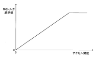
- the “MG torque reference value” is determined based on the map shown in FIG. 2 and the current accelerator opening.
- the MG torque reference value is determined to be larger as the accelerator opening is larger.
- the characteristic of the MG torque reference value with respect to the accelerator opening can change according to various states other than the accelerator opening (for example, distribution of EG torque and MG torque).
- the “MG torque limit value” is determined based on the map shown in FIG. 3 and the current clutch return stroke.
- the MG torque limit value is defined using the meet start point and the release start point.
- the meet start point is the clutch return stroke corresponding to the timing at which C / T shifts from the fully disconnected state to the semi-joined state
- the release start point is C / T from the fully connected state to the semi-joined state. This is a clutch return stroke corresponding to the transition timing.
- the MG torque limit value is within the range where the clutch return stroke is from “0” to “meet start point” (ie, the range corresponding to the C / T completely divided state; see “range a” in FIG. 3).
- the MG torque limit value is The "maximum value” is maintained, and the clutch return stroke is between the "meet start point” and the “release start point” (that is, a range corresponding to the C / T semi-joined state. See “range b” in FIG.
- the MG torque limit value increases from “0” as the clutch return stroke moves from the “meet start point” toward the “release start point”.
- the “maximum value” of the MG torque limit value can be set to a value equal to the current “MG torque reference value”, for example.
- the maps shown in FIGS. 2 and 3 are stored in a predetermined area of the memory in the ECU so as to be updatable.
- the magnitude of the MG torque is normally set to the smaller one of the determined “MG torque reference value” and “MG torque limit value” (hereinafter referred to as “MG torque final reference value”). Adjusted. Note that, when the shift position of the shift lever SL is neutral, the magnitude of the MG torque is maintained at “0”.
- the magnitude of the MG torque is normally determined based on the accelerator opening within the range not exceeding the “MG torque limit value” determined based on the clutch return stroke.
- the driving feeling using the MG torque of the HV-MT vehicle uses the EG torque of the “normal MT vehicle”. It can be closer to the driving feeling.
- a normal MT vehicle refers to a vehicle that has been widely known in the past and includes a manual transmission and a friction clutch, and is mounted only with an internal combustion engine as a power source.
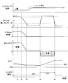
- the accelerator pedal AP, the clutch pedal CP, and the shift lever SL work together to change the shift position from “second gear” to “neutral” due to the driver no longer requesting driving force. It is operated while.
- the operation of the clutch pedal CP is started at the time t1, and the clutch return stroke shifts from the range c to the range b at the time t2 (C / T is in the fully engaged state).
- the clutch return stroke shifts from the range b to the range a at time t3 (C / T shifts from the semi-bonded state to the fully disconnected state), and after time t3, C / T is It is maintained in a completely divided state.
- the accelerator opening starts decreasing toward “0” at time t2, and the accelerator opening is maintained at “0” from time t3.
- the MG torque starts to decrease toward “0” at time t2, and is maintained at “0” from time t3.
- the remaining battery charge SOC is already less than the threshold value TH after time t3.
- the threshold value TH corresponds to a lower limit value of the remaining battery level required for stably rotating the M / G.
- This device is based on the determination that the shift position is “neutral”, C / T is in the joined state, the accelerator opening is “0”, and the remaining battery charge SOC is less than the threshold value TH.
- the charging condition is satisfied.
- the device charges the battery BAT using the EG torque. Specifically, EG torque is used to drive M / G as a generator, and battery BAT is charged using electrical energy obtained by M / G power generation. The charging of the battery BAT is continued until C / T is returned to the completely divided state.
- the charging condition is satisfied at time t4. Therefore, after time t4, the battery BAT is charged by driving the M / G as a generator using the EG torque.
- E / G is stopped before time t4. Therefore, since EG torque is generated after time t4, E / G is started at time t4. The E / G is started using a starter motor (not shown). As a result, the remaining battery charge SOC increases after time t4.
- the friction clutch C / T is in the engaged state and the shift position is in the neutral position (that is, the power between the output shaft of the M / G and the output shaft of the M / T).
- the M / G is driven as a generator using the EG torque. Accordingly, a part of the EG torque is not transmitted to the drive wheels of the vehicle, and therefore a part of the EG torque is not consumed for driving the vehicle. Therefore, the M / G as a generator can be efficiently rotated using the EG torque. As a result, electric energy for battery charging can be generated efficiently. That is, regardless of whether the vehicle is running or stopped, the battery BAT can be efficiently charged using the EG torque when the driver does not require driving force.
- the present invention is not limited to the above embodiment, and various modifications can be employed within the scope of the present invention.
- the friction clutch C / T is in the engaged state and the shift position is in the neutral state, and the M / G is driven as a generator using the EG torque to charge the battery. Of electrical energy is generated.
- M / G cannot be driven using EG torque.
- the alternator ALT may be driven using EG torque instead of M / G, and the battery BAT may be charged using electric energy obtained by the power generation of the alternator ALT.
- the charging condition is “determination that the shift position is neutral, C / T is in the joined state, the accelerator opening is“ 0 ”, and the remaining battery charge SOC is less than the threshold TH.
- the accelerator opening is“ 0 ”
- the remaining battery SOC is less than the threshold TH
- the charging condition is satisfied when the E / G is stopped (see time t4) is shown.
- the charging condition is satisfied when the E / G is operating. It can also happen.
- the operation of the E / G can be continued after the charging condition is satisfied, and the driving of the M / G as a generator can be started immediately by using the already generated EG torque.
- charging of the battery BAT is started at the transition point from the C / T completely divided state to the semi-junction state (see time t4 in FIG. 4).
- the battery BAT has been charged at the time of transition from the semi-junction state of C / T to the fully-junction state, but is terminated at the time of transition to the split state (see time t5 in FIG. 4). May be terminated at the time of transition from the fully joined state to the semi-joined state (see time t5 in FIG. 4).
- the determination that “C / T is in the engaged state” is made based on the clutch return stroke (the detection result of the clutch operation amount sensor S1). May be made based on the determination that “the rotational speed of the output shaft of the engine E / G matches the rotational speed of the input shaft of the manual transmission M / T”.
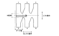
- each shift operation of the shift lever corresponding to a plurality of shift speeds (1st to 5th speed, reverse in FIG. 5 and FIG. 6) selects the shift lever position.
- shift operation operation in the vehicle front-rear direction
- shift operation operation in the vehicle front-rear direction
- the determination that “the shift position is in the neutral position” indicates that the shift lever movement amount (select stroke) in the select operation exceeds a predetermined amount (eg, gate width) as shown in FIGS. Can be made on the basis of that.
- a predetermined amount eg, gate width
- the position in the shift operation direction of the shift lever in the select operation is set to “N”.
- the position of the shift lever in the shift operation direction during the select operation means, for example, the position of the shift lever in the shift operation direction when the shift lever movement amount exceeds a predetermined amount, or the position of the shift lever during the select operation. The average value of the transition of the position in the shift operation direction.
- an area where the position of the shift lever in the shift operation direction is “N ⁇ ⁇ ” is set as an “N area”. Then, based on the fact that the position of the shift lever in the shift operation direction is within the range of “N region”, it can be determined that “the shift position is in neutral”.
- the “N region” may be set based on a range of fluctuation (maximum / minimum) of the position of the shift lever in the shift operation direction during the select operation.
- the determination that “the shift position is in the neutral position” is made by determining the ratio (speed reduction ratio) of the rotational speed of the input shaft to the rotational speed of the output shaft of the manual transmission M / T. This may be based on the fact that none of the reduction ratios of 1st to 5th gears and reverse gears).
Landscapes
- Engineering & Computer Science (AREA)
- Mechanical Engineering (AREA)
- Transportation (AREA)
- Chemical & Material Sciences (AREA)
- Combustion & Propulsion (AREA)
- Automation & Control Theory (AREA)
- Power Engineering (AREA)
- General Engineering & Computer Science (AREA)
- Life Sciences & Earth Sciences (AREA)
- Sustainable Development (AREA)
- Sustainable Energy (AREA)
- Hybrid Electric Vehicles (AREA)
- Electric Propulsion And Braking For Vehicles (AREA)
- Arrangement Or Mounting Of Control Devices For Change-Speed Gearing (AREA)
- Control Of Vehicle Engines Or Engines For Specific Uses (AREA)
- Gear-Shifting Mechanisms (AREA)
- Control Of Transmission Device (AREA)
Abstract
Le présent dispositif de commande de transmission de puissance peut être appliqué à des véhicules hybrides équipés à la fois d'un moteur à combustion interne (EG) et d'un moteur (MG) comme sources d'énergie et comprend une transmission manuelle et un embrayage à friction. La condition de charge est établie lorsque la position de changement de vitesse est dans une position « neutre », l'embrayage à friction est dans un état de coopération, l'ouverture de l'accélérateur est de « 0 » et la charge de batterie restante (SOC) est inférieure à une valeur seuil (TH). Lors de l'établissement de la condition de charge, la charge d'une batterie au moyen d'un couple EG est réalisée. De façon spécifique, le MG est entraîné comme un générateur d'électricité au moyen du couple EG et la batterie est chargée au moyen d'une énergie électrique obtenue par la génération d'énergie par le MG. De cette manière, une batterie destinée à fournir une énergie électrique à un moteur électrique peut être chargée de façon très efficace au moyen d'un couple de moteur à combustion interne dans un véhicule HV-MT.
Priority Applications (3)
| Application Number | Priority Date | Filing Date | Title |
|---|---|---|---|
| US13/984,376 US9085298B2 (en) | 2011-02-09 | 2012-02-08 | Power transmission control device for vehicle |
| CN201280008488.1A CN103429474B (zh) | 2011-02-09 | 2012-02-08 | 车辆的动力传递控制装置 |
| EP12744258.0A EP2674342A4 (fr) | 2011-02-09 | 2012-02-08 | Dispositif de commande de transmission de puissance pour véhicules |
Applications Claiming Priority (2)
| Application Number | Priority Date | Filing Date | Title |
|---|---|---|---|
| JP2011025700A JP5521151B2 (ja) | 2011-02-09 | 2011-02-09 | 車両の動力伝達制御装置 |
| JP2011-025700 | 2011-02-09 |
Publications (1)
| Publication Number | Publication Date |
|---|---|
| WO2012108466A1 true WO2012108466A1 (fr) | 2012-08-16 |
Family
ID=46638679
Family Applications (1)
| Application Number | Title | Priority Date | Filing Date |
|---|---|---|---|
| PCT/JP2012/052864 WO2012108466A1 (fr) | 2011-02-09 | 2012-02-08 | Dispositif de commande de transmission de puissance pour véhicules |
Country Status (5)
| Country | Link |
|---|---|
| US (1) | US9085298B2 (fr) |
| EP (1) | EP2674342A4 (fr) |
| JP (1) | JP5521151B2 (fr) |
| CN (1) | CN103429474B (fr) |
| WO (1) | WO2012108466A1 (fr) |
Families Citing this family (16)
| Publication number | Priority date | Publication date | Assignee | Title |
|---|---|---|---|---|
| GB2447672B (en) | 2007-03-21 | 2011-12-14 | Ford Global Tech Llc | Vehicle manoeuvring aids |
| JP2013103516A (ja) * | 2011-11-10 | 2013-05-30 | Toyota Motor Corp | 車両および車両の制御方法 |
| US9145133B2 (en) * | 2013-11-08 | 2015-09-29 | Ford Global Technologies, Llc | Method and system for selecting an engine operating point for a hybrid vehicle |
| CN103660913B (zh) * | 2013-12-11 | 2016-05-25 | 南京越博动力系统股份有限公司 | 一种单轴并联混合动力客车能量分配方法 |
| US9475479B2 (en) * | 2014-04-29 | 2016-10-25 | Ford Global Technologies, Llc | Electrified vehicle neutral engine start |
| US9493063B2 (en) * | 2014-07-16 | 2016-11-15 | GM Global Technology Operations LLC | Method to allow trickle-charging on a strong hybrid vehicle to balance accessory loads |
| JP2017031034A (ja) * | 2015-08-06 | 2017-02-09 | 信越化学工業株式会社 | SiC単結晶の製造方法 |
| JP6304173B2 (ja) | 2015-08-18 | 2018-04-04 | トヨタ自動車株式会社 | 車両 |
| US10836372B2 (en) * | 2016-08-24 | 2020-11-17 | Ford Global Technologies, Llc | System and method for controlling a hybrid vehicle in park or neutral |
| KR101836289B1 (ko) * | 2016-10-21 | 2018-04-19 | 현대자동차 주식회사 | 친환경 차량용 엔진 클러치 제어 장치 및 방법 |
| US11215244B2 (en) * | 2017-03-22 | 2022-01-04 | Kawasaki Jukogyo Kabushiki Kaisha | Vehicle |
| DE102017110689A1 (de) * | 2017-05-17 | 2018-11-22 | Schaeffler Technologies AG & Co. KG | Verfahren zum Bestimmen eines Fehlers eines Moments einer Brennkraftmaschine in einem Hybridantriebsstrang |
| DE102017214748A1 (de) * | 2017-08-23 | 2019-02-28 | Volkswagen Aktiengesellschaft | Verfahren zum Betreiben eines Fahrerassistenzsystems eines Kraftfahrzeugs sowie Kraftfahrzeug mit einer elektronischen Recheneinrichtung |
| WO2020053939A1 (fr) * | 2018-09-10 | 2020-03-19 | 日産自動車株式会社 | Dispositif de transmission de puissance pour véhicule |
| DE102019107337A1 (de) * | 2019-03-22 | 2020-09-24 | Schaeffler Technologies AG & Co. KG | Verfahren zur Ermittlung einer Drehmomentübertragungseigenschaft einer Kupplung durch einen ausgewählten Abtriebsdrehzahlgradienten |
| JP7388334B2 (ja) | 2020-10-22 | 2023-11-29 | トヨタ自動車株式会社 | 二次電池の劣化判定装置 |
Citations (7)
| Publication number | Priority date | Publication date | Assignee | Title |
|---|---|---|---|---|
| JPH05222946A (ja) * | 1992-02-14 | 1993-08-31 | Toyota Motor Corp | 過給機付エンジンの制御装置 |
| JP2000224710A (ja) | 1999-01-27 | 2000-08-11 | Mitsubishi Motors Corp | ハイブリッド車 |
| JP2000343965A (ja) * | 1999-06-08 | 2000-12-12 | Nissan Diesel Motor Co Ltd | ハイブリッド車両 |
| JP2001235030A (ja) * | 2000-02-24 | 2001-08-31 | Isuzu Motors Ltd | 変速機のシフトアシスト装置 |
| JP2002089307A (ja) * | 2000-09-14 | 2002-03-27 | Toyota Motor Corp | 可変気筒エンジンの制御装置および車両の制御装置 |
| JP2007030599A (ja) * | 2005-07-25 | 2007-02-08 | Nissan Motor Co Ltd | エンジンの回転速度表示装置 |
| JP2010030329A (ja) * | 2008-07-25 | 2010-02-12 | Nissan Motor Co Ltd | 変速レバーの操作位置検出装置 |
Family Cites Families (7)
| Publication number | Priority date | Publication date | Assignee | Title |
|---|---|---|---|---|
| DE2943519A1 (de) * | 1979-10-27 | 1981-05-07 | Volkswagenwerk Ag | Antrieb fuer ein fahrzeug mit einer brennkraftmaschine und einem elektromotor |
| JP2973796B2 (ja) * | 1993-10-07 | 1999-11-08 | トヨタ自動車株式会社 | ハイブリッド電気自動車の空調制御方法 |
| KR100471551B1 (ko) * | 1996-05-24 | 2005-04-14 | 히노지도샤코교 가부시기가이샤 | 차재전지의제어장치 |
| JP2004076841A (ja) * | 2002-08-16 | 2004-03-11 | Suzuki Motor Corp | 車両用自動変速制御装置 |
| JP4492585B2 (ja) * | 2006-05-29 | 2010-06-30 | 日産自動車株式会社 | ハイブリッド車両の制御装置及びハイブリッド車両の制御方法。 |
| BRPI0907218B1 (pt) * | 2008-01-14 | 2022-08-23 | Toyota Jidosha Kabushiki Kaisha | Método para carregamento de célula secundária de íon lítio e veículo elétrico híbrido |
| GB2466040B (en) * | 2008-12-09 | 2012-12-05 | Ford Global Tech Llc | A method and apparatus for establishing the engagement state of a manual transmission |
-
2011
- 2011-02-09 JP JP2011025700A patent/JP5521151B2/ja not_active Expired - Fee Related
-
2012
- 2012-02-08 US US13/984,376 patent/US9085298B2/en not_active Expired - Fee Related
- 2012-02-08 CN CN201280008488.1A patent/CN103429474B/zh not_active Expired - Fee Related
- 2012-02-08 EP EP12744258.0A patent/EP2674342A4/fr not_active Withdrawn
- 2012-02-08 WO PCT/JP2012/052864 patent/WO2012108466A1/fr active Application Filing
Patent Citations (7)
| Publication number | Priority date | Publication date | Assignee | Title |
|---|---|---|---|---|
| JPH05222946A (ja) * | 1992-02-14 | 1993-08-31 | Toyota Motor Corp | 過給機付エンジンの制御装置 |
| JP2000224710A (ja) | 1999-01-27 | 2000-08-11 | Mitsubishi Motors Corp | ハイブリッド車 |
| JP2000343965A (ja) * | 1999-06-08 | 2000-12-12 | Nissan Diesel Motor Co Ltd | ハイブリッド車両 |
| JP2001235030A (ja) * | 2000-02-24 | 2001-08-31 | Isuzu Motors Ltd | 変速機のシフトアシスト装置 |
| JP2002089307A (ja) * | 2000-09-14 | 2002-03-27 | Toyota Motor Corp | 可変気筒エンジンの制御装置および車両の制御装置 |
| JP2007030599A (ja) * | 2005-07-25 | 2007-02-08 | Nissan Motor Co Ltd | エンジンの回転速度表示装置 |
| JP2010030329A (ja) * | 2008-07-25 | 2010-02-12 | Nissan Motor Co Ltd | 変速レバーの操作位置検出装置 |
Also Published As
| Publication number | Publication date |
|---|---|
| EP2674342A1 (fr) | 2013-12-18 |
| US20140011632A1 (en) | 2014-01-09 |
| CN103429474A (zh) | 2013-12-04 |
| JP5521151B2 (ja) | 2014-06-11 |
| JP2012162215A (ja) | 2012-08-30 |
| CN103429474B (zh) | 2016-01-20 |
| US9085298B2 (en) | 2015-07-21 |
| EP2674342A4 (fr) | 2018-04-04 |
Similar Documents
| Publication | Publication Date | Title |
|---|---|---|
| JP5521151B2 (ja) | 車両の動力伝達制御装置 | |
| US7789177B2 (en) | Control apparatus and control method for drive apparatus of hybrid vehicle | |
| US7498757B2 (en) | Control device for a hybrid electric vehicle | |
| US8540603B2 (en) | Vehicle power transmission control device | |
| JP5367682B2 (ja) | 車両の動力伝達制御装置 | |
| CN103010205B (zh) | 车辆的动力传递控制装置 | |
| WO2013150964A1 (fr) | Dispositif de commande d'un véhicule électrique hybride | |
| JP5422544B2 (ja) | 車両の動力伝達制御装置 | |
| KR20180067984A (ko) | 마일드 하이브리드 차량의 mhsg 제어 방법 및 장치 | |
| US10737682B2 (en) | Drive force control system for hybrid vehicle | |
| JP2018052320A (ja) | ハイブリッド車両システムの制御装置及び制御方法 | |
| JP5821475B2 (ja) | ハイブリッド車両の制御装置 | |
| JP5769956B2 (ja) | 車両の動力伝達制御装置 | |
| JP5715848B2 (ja) | 車両の動力伝達制御装置 | |
| JP5185994B2 (ja) | 車両の動力伝達制御装置 | |
| JP4086077B2 (ja) | 内燃機関の始動制御装置 | |
| JP2004251452A (ja) | ハイブリッド車両の制御装置 | |
| JP5469039B2 (ja) | ハイブリッド車両 | |
| JP5226847B2 (ja) | 車両の動力伝達制御装置 | |
| WO2012081280A1 (fr) | Dispositif de commande de transmission de puissance pour véhicule | |
| WO2012077382A1 (fr) | Dispositif de commande de transmission de puissance de véhicule | |
| JP2013144544A (ja) | 車両の動力伝達制御装置 | |
| JP2012153244A (ja) | 車両の動力伝達制御装置 |
Legal Events
| Date | Code | Title | Description |
|---|---|---|---|
| 121 | Ep: the epo has been informed by wipo that ep was designated in this application |
Ref document number: 12744258 Country of ref document: EP Kind code of ref document: A1 |
|
| NENP | Non-entry into the national phase |
Ref country code: DE |
|
| WWE | Wipo information: entry into national phase |
Ref document number: 2012744258 Country of ref document: EP |
|
| WWE | Wipo information: entry into national phase |
Ref document number: 13984376 Country of ref document: US |