WO2012108272A1 - 管群外筒の組立方法及び蒸気発生器の組立方法、管群外筒の移動装置 - Google Patents
管群外筒の組立方法及び蒸気発生器の組立方法、管群外筒の移動装置 Download PDFInfo
- Publication number
- WO2012108272A1 WO2012108272A1 PCT/JP2012/051675 JP2012051675W WO2012108272A1 WO 2012108272 A1 WO2012108272 A1 WO 2012108272A1 JP 2012051675 W JP2012051675 W JP 2012051675W WO 2012108272 A1 WO2012108272 A1 WO 2012108272A1
- Authority
- WO
- WIPO (PCT)
- Prior art keywords
- tube group
- group outer
- outer cylinder
- tube
- lower body
- Prior art date
- Legal status (The legal status is an assumption and is not a legal conclusion. Google has not performed a legal analysis and makes no representation as to the accuracy of the status listed.)
- Ceased
Links
Images







Classifications
-
- F—MECHANICAL ENGINEERING; LIGHTING; HEATING; WEAPONS; BLASTING
- F22—STEAM GENERATION
- F22B—METHODS OF STEAM GENERATION; STEAM BOILERS
- F22B1/00—Methods of steam generation characterised by form of heating method
- F22B1/02—Methods of steam generation characterised by form of heating method by exploitation of the heat content of hot heat carriers
- F22B1/023—Methods of steam generation characterised by form of heating method by exploitation of the heat content of hot heat carriers with heating tubes for nuclear reactors, as long as they are not classified according to a specified heating fluid, in another group
-
- F—MECHANICAL ENGINEERING; LIGHTING; HEATING; WEAPONS; BLASTING
- F28—HEAT EXCHANGE IN GENERAL
- F28D—HEAT-EXCHANGE APPARATUS, NOT PROVIDED FOR IN ANOTHER SUBCLASS, IN WHICH THE HEAT-EXCHANGE MEDIA DO NOT COME INTO DIRECT CONTACT
- F28D7/00—Heat-exchange apparatus having stationary tubular conduit assemblies for both heat-exchange media, the media being in contact with different sides of a conduit wall
- F28D7/06—Heat-exchange apparatus having stationary tubular conduit assemblies for both heat-exchange media, the media being in contact with different sides of a conduit wall the conduits having a single U-bend
-
- F—MECHANICAL ENGINEERING; LIGHTING; HEATING; WEAPONS; BLASTING
- F28—HEAT EXCHANGE IN GENERAL
- F28F—DETAILS OF HEAT-EXCHANGE AND HEAT-TRANSFER APPARATUS, OF GENERAL APPLICATION
- F28F9/00—Casings; Header boxes; Auxiliary supports for elements; Auxiliary members within casings
- F28F9/007—Auxiliary supports for elements
- F28F9/013—Auxiliary supports for elements for tubes or tube-assemblies
-
- F—MECHANICAL ENGINEERING; LIGHTING; HEATING; WEAPONS; BLASTING
- F28—HEAT EXCHANGE IN GENERAL
- F28D—HEAT-EXCHANGE APPARATUS, NOT PROVIDED FOR IN ANOTHER SUBCLASS, IN WHICH THE HEAT-EXCHANGE MEDIA DO NOT COME INTO DIRECT CONTACT
- F28D21/00—Heat-exchange apparatus not covered by any of the groups F28D1/00 - F28D20/00
- F28D2021/0019—Other heat exchangers for particular applications; Heat exchange systems not otherwise provided for
- F28D2021/0054—Other heat exchangers for particular applications; Heat exchange systems not otherwise provided for for nuclear applications
Definitions
- the present invention relates to a steam generator used as a heat exchanger in a nuclear power plant, a method of assembling a tube group outer cylinder that supports a heat transfer tube group composed of a large number of heat transfer tubes, a method of assembling a steam generator, and a method of The present invention relates to a cylinder moving device.
- a pressurized water reactor For example, in a pressurized water reactor (PWR), light water is used as a reactor coolant and neutron moderator, and high temperature and high pressure water that does not boil throughout the core is sent to a steam generator. Steam is generated by heat exchange, and the steam is sent to a turbine generator for power generation.
- the heat of the high-temperature and high-pressure primary cooling water is transmitted to the secondary cooling water by the steam generator, and steam is generated by the secondary cooling water.
- primary cooling water flows inside a large number of thin heat transfer tubes, heat is transferred to secondary cooling water flowing outside, and steam is generated, and a turbine is rotated by the steam to generate electric power.
- a tube group outer cylinder is disposed at a predetermined distance from the inner wall surface in a hollow hermetically sealed body portion, and a plurality of inverted U-shaped heat transfer tubes are arranged in the tube group outer cylinder.
- An end portion of each heat transfer tube is supported by the tube plate, and an inlet side water chamber mirror and an outlet side water chamber mirror of the primary cooling water are formed at the lower end portion of the trunk portion.
- an inlet portion of the secondary cooling water is provided in the trunk portion above the outer tube of the tube group, and a steam / water separator and a moisture separator are arranged side by side, above which steam is placed. There is an exit.
- the primary cooling water is supplied from the cooling water pipe to the plurality of heat transfer tubes through the inlet side water chamber mirror, while the secondary cooling water is supplied from the inlet portion into the trunk portion. Then, heat exchange is performed between the primary cooling water (hot water) flowing in the plurality of heat transfer tubes and the secondary cooling water (cold water) circulating in the body, so that the secondary cooling water absorbs heat. Water vapor is generated. Then, moisture is removed from the generated steam by the steam separator, and the steam from which moisture has been removed by the moisture separator is discharged from the steam outlet, while the primary cooling water that has finished heat exchange is discharged from the outlet side water. It is discharged from the mirror.
- Patent Document 1 As such a steam generator, there is one described in Patent Document 1 below. Moreover, there exists what was described in the following patent document 2 as what assembled by inserting a pipe group outer cylinder in a trunk
- the body When assembling the conventional steam generator described above, the body is divided into an upper body and a lower body, and a steam separator, a moisture separator, etc. are accommodated in the upper body, while the tube body is outside the lower body.
- a cylinder, a plurality of heat transfer tubes, and the like are accommodated, and in this state, the upper body and the lower body are laid sideways and joined together by welding.
- the lower body In this case, the lower body is supported in the vertical direction, and the tube group outer tube is inserted into the lower body from above. Therefore, these assembly factories must be built as buildings with high ceilings, or must be built as buildings with low floors by digging the ground, resulting in high building costs. End up.
- the pipe group outer cylinder is suspended and supported by a crane with respect to the vertically supported lower trunk, and the pipe group outer cylinder is lowered and inserted into the lower trunk. In this case, the pipe group outer cylinder shakes. There is a risk that it will be damaged by contact with the lower body.
- the present invention solves the above-described problems, and provides a tube group outer tube assembling method, a steam generator assembling method, and a tube group outer tube moving device that improve the workability of assembling work. With the goal.
- the tube group outer tube assembly method of the present invention for achieving the above object is a tube group outer tube assembly method in which a tube group outer tube on which a heat transfer tube group is supported is assembled in a body portion, The tube body outer cylinder is inserted into the lower body supported sideways from the upper side, and the tube body outer cylinder is inserted into the lower body at a predetermined insertion position. It is characterized by being fixed to.
- the tube group outer tube is moved to the predetermined insertion position on the inner peripheral surface of the lower body by a plurality of moving devices detachably mounted on the outer peripheral part. It is a feature.
- the tube group outer cylinder can be appropriately moved into the lower body by the moving device, the lifting of the tube group outer cylinder is unnecessary, and shaking can be prevented, and workability in assembly work can be improved.
- the tube group outer tube has a plurality of reinforcing rings mounted therein at predetermined intervals in the longitudinal direction, and a moving device corresponds to the reinforcing ring in the tube group outer tube. It is characterized by moving in support of the position.
- deformation of the tube group outer cylinder can be prevented by the movement device supporting and moving the position corresponding to the reinforcing ring in the tube group outer cylinder.
- the tube group outer tube is positioned by fitting a lower notch portion into a positioning pipe attached to a lower portion of the lower body. Yes.
- the pipe group outer cylinder can be positioned with high accuracy relative to the lower cylinder by fitting the notch portion of the pipe group outer cylinder to the positioning pipe of the lower cylinder and positioning.
- the steam generator assembling method of the present invention includes a tube group outer cylinder inserting step of inserting a tube group outer cylinder supported sideways from the upper side into a lower cylinder supported sideways, A step of assembling the tube support plate and the heat transfer tube with respect to the tube group outer tube, and a moisture separator inside the tube body outer tube and the heat transfer tube group accommodated therein and supported on the side And a body part joining step for joining the upper body in which the steam-water separator is accommodated.
- the tube group outer tube moving device of the present invention is a movable device that can move the tube group outer tube when inserting the tube group outer tube supported sideways from the upper side into the lower body supported sideways.
- An apparatus a frame that is detachable in the longitudinal direction of the tube group outer cylinder, a lifting device that is capable of raising and lowering the tube group outer cylinder via the frame, a carriage that is detachable from the frame, and a frame And a conversion device that changes the traveling direction of the carriage.
- the tube group outer tube is easily moved into the lower shell by the moving device.
- the moving device adjusts the circumferential position of the tube group outer tube. This can be performed, and the tube group outer cylinder can be mounted with high accuracy.
- the assembly work is performed in a state where each member is supported on its side, so that the roof is highly assembled. Manufacturing costs can be reduced by eliminating the need for a factory building, and shaking can be prevented by eliminating the need for lifting the members. As a result, workability in assembly operations can be improved.
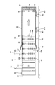
- FIG. 1 is a side view illustrating a method for assembling a tube group outer tube according to an embodiment of the present invention.
- FIG. 2 is a front view illustrating a method of assembling the tube group outer cylinder of the present embodiment.
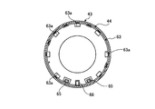
- 3 is a cross-sectional view taken along the line III-III in FIG.
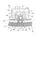
- FIG. 4 is a front view of the tube group outer cylinder moving device in the steam generator of the present embodiment.
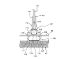
- FIG. 5 is a side view of the tube group outer cylinder moving device.
- FIG. 6 is a plan view of the tube group outer cylinder moving device.
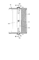
- FIG. 7 is a front view of the lifting jack.
- FIG. 8 is a cross-sectional view of the lower shell showing the attachment state of the positioning pipe in the lower shell.
- FIG. 9 is a cross-sectional view taken along the line IX-IX in FIG.
- FIG. 10 is a schematic view showing a method for assembling the tube group outer cylinder of the present embodiment.
- FIG. 11 is a schematic view showing a method for assembling the tube group outer cylinder of the present embodiment.
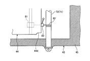
- FIG. 12 is an enlarged cross-sectional view of a main part showing a tube group outer cylinder positioning method.
- FIG. 13 is a schematic view showing a method for assembling the tube group outer cylinder of the present embodiment.
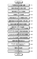
- FIG. 14 is a flowchart showing the procedure of the method for assembling the tube group outer cylinder of this embodiment.
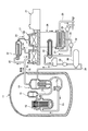
- FIG. 15 is a schematic configuration diagram of a nuclear power plant to which the steam generator of the present embodiment is applied.
- FIG. 16 is a schematic configuration diagram illustrating a steam generator according to the present embodiment.
- FIG. 1 is a side view showing a method for assembling a tube group outer cylinder according to one embodiment of the present invention
- FIG. 2 is a front view showing a method for assembling a tube group outer cylinder according to this embodiment
- FIG. FIG. 4 is a front view of a tube group outer tube moving device in the steam generator of this embodiment
- FIG. 5 is a side view of the tube group outer tube moving device
- FIG. 7 is a front view of an elevating jack
- FIG. 8 is a cross-sectional view of a lower shell showing a mounting state of a positioning pipe in the lower shell
- FIG. 9 is an IX-IX of FIG.
- FIG. 10 is a schematic view showing an assembling method of the tube group outer cylinder of the present embodiment
- FIG. 10 is a schematic view showing an assembling method of the tube group outer cylinder of the present embodiment
- FIG. 11 is a schematic view showing an assembling method of the tube group outer cylinder of the present embodiment
- FIG. FIG. 13 is a schematic view showing a method of assembling the tube group outer cylinder of this embodiment
- FIG. 14 shows the procedure of the method of assembling the tube group outer cylinder of this embodiment.
- FIG. 15 is a schematic configuration diagram of a nuclear power plant to which the steam generator of the present embodiment is applied
- FIG. 16 is a schematic configuration diagram illustrating the steam generator of the present embodiment.
- the nuclear reactor of this embodiment uses light water as a reactor coolant and neutron moderator, and generates high-temperature and high-pressure water that does not boil over the entire core and sends this high-temperature and high-pressure water to a steam generator to generate steam by heat exchange.
- This is a pressurized water reactor (PWR) that sends this steam to a turbine generator to generate electricity.
- PWR pressurized water reactor
- a pressurized water reactor 12 and a steam generator 13 are stored in a reactor containment vessel 11, and this pressurized water type is stored.
- the reactor 12 and the steam generator 13 are connected via cooling water pipes 14 and 15, a pressurizer 16 is provided in the cooling water pipe 14, and a cooling water pump 15 a is provided in the cooling water pipe 15. .
- light water is used as the moderator and primary cooling water (cooling material), and the primary cooling system is maintained at a high pressure of about 150 to 160 atm by the pressurizer 16 in order to suppress boiling of the primary cooling water in the core. You are in control.
- the pressurized water reactor 12 light water is heated as the primary cooling water by the low-enriched uranium or MOX as the fuel (nuclear fuel), and the high-temperature primary cooling water is cooled with the pressurizer 16 maintained at a predetermined high pressure. It is sent to the steam generator 13 through the water pipe 14. In the steam generator 13, heat exchange is performed between the high-pressure and high-temperature primary cooling water and the secondary cooling water, and the cooled primary cooling water is returned to the pressurized water reactor 12 through the cooling water pipe 15.
- the steam generator 13 is connected to a steam turbine 17 via a cooling water pipe 18, and the steam turbine 17 includes a high pressure turbine 19 and a low pressure turbine 20, and a generator 21 is connected thereto. Further, a moisture separation heater 22 is provided between the high pressure turbine 19 and the low pressure turbine 20, and a cooling water branch pipe 23 branched from the cooling water pipe 18 is connected to the moisture separation heater 22. On the other hand, the high pressure turbine 19 and the moisture separation heater 22 are connected by a low temperature reheat pipe 24, and the moisture separation heater 22 and the low pressure turbine 20 are connected by a high temperature reheat pipe 25.
- the low-pressure turbine 20 of the steam turbine 17 has a condenser 26, and a condenser pipe 26 and a drain pipe 28 for supplying and discharging cooling water (for example, seawater) are connected to the condenser 26.
- This intake pipe 27 has a circulating water pump 29, and the other end portion thereof is disposed in the sea together with the drain pipe 28.
- the condenser 26 is connected to a deaerator 31 through a cooling water pipe 30, and a condensate pump 32 and a low-pressure feed water heater 33 are provided in the cooling water pipe 30.
- the deaerator 31 is connected to the steam generator 13 via a cooling water pipe 34, and a water supply pump 35 and a high-pressure feed water heater 36 are provided in the cooling water pipe 34.
- the steam generated by performing heat exchange with the high-pressure and high-temperature primary cooling water in the steam generator 13 is sent to the steam turbine 17 (from the high-pressure turbine 19 to the low-pressure turbine 20) through the cooling water pipe 18, and this steam is generated. Then, the steam turbine 17 is driven to generate power by the generator 21. At this time, the steam from the steam generator 13 drives the high pressure turbine 19, and then the moisture contained in the steam is removed and heated by the moisture separator / heater 22, and then the low pressure turbine 20 is driven.
- the steam that has driven the steam turbine 17 is cooled with seawater in the condenser 26 to become condensed water, and is heated by the low-pressure steam extracted from, for example, the low-pressure turbine 20 in the low-pressure feed water heater 33 and deaerated. After impurities such as dissolved oxygen and uncondensed gas (ammonia gas) are removed by the vessel 31, the high pressure feed water heater 36 is heated by, for example, high pressure steam extracted from the high pressure turbine 19, and then the steam generator 13. Returned.
- the body portion 41 has a sealed hollow cylindrical shape, and the lower portion has a slightly smaller diameter with respect to the upper portion. ing.
- the body portion 41 is configured by joining an upper body 42 and a lower body 43 by welding.
- a tube group outer cylinder 44 having a cylindrical shape with a predetermined distance from the inner wall surface of the lower barrel 43 is disposed in the lower barrel 43 of the trunk portion 41, and a lower end portion extends to the vicinity of the tube plate 45. Yes.
- a plurality of tube support plates 46 are disposed in correspondence with a predetermined height position, and are supported by a plurality of stay rods 47 extending upward from the tube plate 45. ing.
- the tube group outer tube 44 is provided therein with a heat transfer tube group 49 including a plurality of heat transfer tubes 48 having an inverted U shape, and an end portion of each heat transfer tube 48 is expanded to the tube plate 45.
- the intermediate portion is supported by a plurality of tube support plates 46.
- the tube support plate 46 has a large number of through holes (not shown), and each heat transfer tube 48 is inserted into and supported by the through holes.
- the lower body 43 has a water chamber mirror 50 fixed to the lower end thereof, and is divided into an entrance chamber 52 and an exit chamber 53 by a partition wall 51, and an inlet nozzle 54 and an outlet nozzle 55 are formed.
- One end portion of the first chamber communicates with the entrance chamber 52, and the other end portion communicates with the exit chamber 53.
- the inlet nozzle 54 is connected to the cooling water pipe 14 described above, while the outlet nozzle 55 is connected to the cooling water pipe 15.
- the upper body 42 is provided with an air / water separator 56 that separates the feed water into steam and hot water, and a moisture separator 57 that removes the moisture of the separated steam and makes it close to dry steam. It has been.
- the upper body 42 is provided with a water supply pipe 58 for supplying secondary cooling water into the body 41 between the heat transfer tube group 49 and the steam separator 56, while a steam outlet is provided on the ceiling. 59 is formed. Then, the body 41 circulates the secondary cooling water supplied from the water supply pipe 58 into the body 41 between the body 41 and the tube group outer tube 44 and circulates upward in the tube plate 45.
- the cooling water pipe 34 is connected to the water supply pipe 58, while the cooling water pipe 18 is connected to the steam outlet 59.
- the primary cooling water heated in the pressurized water reactor 12 is sent to the entrance chamber 52 of the steam generator 13 through the coolant pipe 14, circulates through the numerous heat transfer tubes 48, and reaches the exit chamber 53.
- the secondary cooling water cooled by the condenser 26 is sent to the water supply pipe 58 of the steam generator 13 through the cooling water pipe 34 and flows through the heat transfer pipe 48 through the water supply path 60 in the trunk portion 41.
- Exchange heat with water primary cooling water. That is, heat is exchanged between the high-pressure and high-temperature primary cooling water and the secondary cooling water in the trunk portion 41, and the cooled primary cooling water passes from the outlet chamber 53 through the cooling water pipe 15 to the pressurized water reactor 12.
- the secondary cooling water subjected to heat exchange with the high-pressure and high-temperature primary cooling water rises in the body 41 and is separated into steam and hot water by the steam-water separator 56, and this is separated by the moisture separator 57. After the moisture of the steam is removed, the steam is sent to the steam turbine 17 through the cooling water pipe 18.
- the lower body 43 has a cylindrical shape, and an enlarged diameter portion 43 a is formed so that the upper portion widens upward at a predetermined angle.
- the tube sheet 45 is fixed to the lower end portion by welding.
- the lower body 43 is supported sideways by support rollers 61a and 62a of two support devices 61 and 62 installed on the floor, and is rotatable in the circumferential direction.
- the tube group outer cylinder 44 has a cylindrical shape and has an outer diameter smaller than the inner diameter of the lower body 43, and can be inserted into the lower body 43 with a predetermined gap. Further, since the tube group outer cylinder 44 is formed of a thin plate material, a reinforcing ring 63 having a disk ring shape is fixed to the inner peripheral surface at a predetermined interval (for example, welding). The tube group outer cylinder 44 is supported by being suspended by a suspension member 64 from a crane (not shown), and can be inserted from the lower end side to the upper end side of the lower trunk 43.
- the tube group outer cylinder 44 has three moving devices 65, 66, and 67 detachably attached to the lower portion thereof at predetermined intervals in the longitudinal direction. The tube group outer cylinder 44 is inserted into the lower body 43. Thereafter, the first, second, and third moving devices 65, 66, and 67 can be moved to a predetermined joining position.
- the reinforcing ring 63 is fixed at a position to be supported by the suspension member 64 from the crane. It has become a position.
- the positions supported by the first, second, and third moving devices 65, 66, and 67 are also positions where the reinforcing ring 63 is fixed. That is, after the tube group outer cylinder 44 is assembled to the lower body 43, a plurality of tube support plates 46 (see FIG. 16) are attached at predetermined intervals in the longitudinal direction.
- a plurality of mounting openings 44a are formed at the positions, and a mounting plate 44b (see FIG.
- a jack assembly (not shown) for adjusting the position of the tube support plate 46 with respect to the tube group outer tube 44 is mounted.
- the tube group outer cylinder 44 is mounted with first, second, and third moving devices 65, 66, and 67 in a mounting opening 44a located at a lower portion supported sideways.
- Each of the first, second, and third moving devices 65, 66, and 67 forms a pair, and is arranged side by side in the circumferential direction at the lower portion in the vertical direction of the tube group outer tube 44 that is supported on its side. These are mounted in the mounting openings 44a.
- the first, second, and third lifting jacks 68, 69, and 70 are detachable between the two devices.
- first, second, and third moving devices 65, 66, and 67 will be described in detail. Since the moving devices 65, 66, and 67 have the same configuration, the first moving device 65 is provided. Only will be described.
- the reinforcing ring 63 corresponding to the mounting opening 44 a formed in the tube group outer cylinder 44. Is fixed, and a notch 63 a is formed in the reinforcing ring 63.
- the first moving device 65 is detachably attached to the pair of attachment plates 101 fixed to the notch 63a of the reinforcing ring 63.
- the first moving device 65 includes a pedestal 102 that can be attached to and detached from a mounting plate 101 of a reinforcing ring 63 fixed to the tube group outer cylinder 44, and a first tube unit outer cylinder 44 that can be moved up and down via the gantry 102.
- the reinforcing ring 63 has a plurality of notches 63a formed on the outer peripheral portion, and the reinforcing ring 63 is sandwiched from both sides corresponding to the notched portion 63a located at the lower part of the tube group outer cylinder in a sideways state.
- the pair of mounting plates 101 are fixed by welding.
- the pair of mounting plates 101 has three mounting holes 101a corresponding to the notches 63a.
- the mounting plate 111 is inserted between a pair of mounting plates 101, and three mounting bolts 112 are fastened through the mounting holes 101a and mounting holes (not shown) of the mounting plate 111.
- the reinforcing ring 63 is fixed to the outer tube 44 of the tube group.
- the mounting plate 111 has a horizontal support plate 113 fixed thereto by welding, and a reinforcing plate 114 is fixed to the lower surface of the support plate 113 by fixing bolts 115.
- the reinforcing plate 114 has a mounting plate 116 of the chill tank 103 in close contact with the lower surface portion, and is detachably fixed by a plurality of bolts (reverse rotation preventing members) 117.
- the chill tank 103 has a plurality of wheels 118 and can run on the inner wall surface of the lower body 43 in the circumferential direction or the longitudinal direction (axial direction).
- the support plate 113 and the reinforcing plate 114 are fixed to the bearing portion 119 so as to penetrate in the vertical direction, and the integral support shaft 120 extending upward from the mounting plate 116 of the chill tank 103 rotates to the bearing portion 119.
- Two operation handles 121 are attached to the upper end portion of the support shaft 120.
- the mount 102 is constituted by the mounting plate 111, the support plate 113, and the like. Further, the conversion device 104 is configured by the bearing portion 119, the support shaft 120, and the operation handle 121.
- the 1st raising / lowering jack 68 has the jack main body 131, the support plate 132, and the two leg parts 133, as shown in FIG.
- the lower part of the jack body 131 is fixed to the support plate 132, and the upper part has a drive rod 131a that can be vertically expanded and contracted.
- the support plate 132 has two leg portions 133 fixed to the lower part thereof penetrating through the screw holes 44 c of the attachment plate 44 b fixed to the attachment opening 44 a of the tube group outer tube 44.
- the tube group outer tube 44 has a plurality of mounting openings 44a formed therein and a reinforcing ring 63 fixed thereto.
- the attachment plate 44b is fixed to a part.
- the reinforcing ring 63 is formed with a plurality of notches 63a, and the mounting plate 101 is fixed corresponding to the notches 63a.
- the first moving device 65 inserts the mounting plate 111 between the mounting plates 101 and fastens them with the three mounting bolts 112, thereby allowing the tube group outer tube 44 to pass through the mounting plate 101, that is, the reinforcing ring 63. Can be fixed to.
- the first lifting jack 68 is mounted on the tube group outer cylinder 44 by inserting the two leg parts 133 into the screw holes 44c of the mounting plate 44b fixed to the mounting opening 44a of the tube group outer cylinder 44. be able to.
- the tube group outer cylinder 44 can be raised with respect to the lower trunk
- the plurality of bolts 117 are loosened, and the operation handle 121 is rotated 90 degrees to change the direction of the chill tank 103 by 90 degrees, and the traveling direction thereof is between the longitudinal direction of the lower body 43 and the circumferential direction. Can be converted.
- the lower body 43 can be positioned when the tube group outer tube 44 is inserted into the inside and joined to a predetermined position. As shown in FIGS. 8 and 9, the lower body 43 has four inspection openings 43b formed at equal intervals in the circumferential direction (90 degree intervals) at the lower part in the longitudinal direction. Positioning pipes 71 and 72 are inserted into 43b.
- the positioning pipe 71 has a length longer than the outer diameter of the lower body 43, a flange 71a is formed at the base end, and a suspension hole 71b is formed at both ends.
- the positioning pipe 72 is shorter than the outer diameter of the lower body 43 and has a length of about 1 ⁇ 2 of the radius.
- a flange 72a is formed at the base end portion and a suspension hole 72b is formed at both end portions. Has been.
- the positioning pipe 71 is passed through two inspection openings 43b formed in the lower body 43, and the flange 73 is fixed to the distal end portion at a position where the flange 71a contacts the outer peripheral surface of the lower body 43.
- the stopper is secured to the lower body 43 with fixing bolts 74.
- two positioning pipes 72 are installed, penetrated through the remaining two inspection openings 43 b formed in the lower body 43, and the fixing bolt 75 is positioned at a position where the flange 72 a contacts the outer peripheral surface of the lower body 43. It fixes to the lower trunk
- the tube group outer tube 44 has four inspection notches 44d at equal intervals in the circumferential direction (90 degree intervals) corresponding to the four inspection openings 43b formed in the lower body 43 at the lower part in the longitudinal direction. Is formed. Therefore, when the tube group outer cylinder 44 inserted into the lower barrel 43 is moved by the moving devices 65, 66, and 67, the inspection openings 43b are fitted into the positioning pipes 71 and 72, thereby the lower barrel.
- the tube group outer tube 44 can be positioned in the longitudinal direction and the circumferential direction with respect to 43.
- the method of assembling the tube group outer tube 44 of this embodiment is a method of assembling the tube group outer tube 44 on which the heat transfer tube group 49 is supported in the lower body 43 constituting the body portion 41 as shown in FIG. Then, the tube group outer cylinder 44 supported sideways from the upper side is inserted into the lower body 43 supported sideways, and the tube group outer cylinder 44 is fixed to the lower body 43 at a predetermined insertion position.
- the tube group outer cylinder 44 is moved to the predetermined insertion position on the inner peripheral surface of the lower body 43 by three moving devices 65, 66, 67 which are detachably attached to the outer peripheral portion.
- the tube group outer cylinder 44 has a plurality of reinforcement rings 63 mounted on the inside thereof at predetermined intervals in the longitudinal direction, and the moving devices 65, 66, and 67 support positions corresponding to the reinforcement ring 63 in the tube group outer cylinder 44. To move. Further, the tube group outer cylinder 44 is positioned by fitting the lower notch portion 44 d to the positioning pipes 71 and 72 mounted on the lower portion of the lower body 43.
- the assembly method of the steam generator 13 of the present embodiment includes a tube group outer tube insertion step of inserting the tube group outer tube 44 supported sideways from the upper side of the lower body 43 supported sideways, The process of assembling the tube support plate 46 and the heat transfer tube 48 to the tube group outer tube 44 in the lower shell 43, and the lower shell 43 in which the tube group outer tube 44 and the heat transfer tube group 49 are accommodated and supported on the side. And a body part joining step for joining the upper body 42 in which the moisture separator 57 and the steam separator 56 are accommodated.
- step S11 the lower body 43 is laid down and supported by the support devices 61 and 62.
- step S12 the tube group outer cylinder 44 is laid down and supported by the suspension member 64 suspended from the crane.
- step S13 three moving devices 65, 66, and 67 (elevating jacks 68, 69, and 70) are attached to the side portion of the tube group outer cylinder 44 that is supported on its side, that is, the lower portion in FIG.
- step S ⁇ b> 14 the positioning pipes 71 and 72 are attached to the lower body 43.
- step S15 the lower end portion is inserted into the lower body 43 while operating the crane and lifting and supporting the tube group outer tube 44 by the suspension member 64 as shown in FIG. .
- the lower end portion of the tube group outer tube 44 is inserted into the lower body 43, the lower end portion of the tube group outer tube 44 is supported by the lower body 43 via the first moving device 65, so that the process proceeds to step S16.
- the support position of the tube group outer cylinder 44 by the suspension member 64 is changed from the position of the two-dot chain line shown in FIG. 10 to the position of the solid line.
- the lower end portion is supported on the lower body 43 by the first moving device 65
- the middle portion is supported on the lower case 43 by the second moving device 66
- the upper end portion is supported on the lower case 43 by the third moving device 67. Is done.
- step S17 since the tube group outer tube 44 is supported by the three moving devices 65, 66, and 67, the support by the crane suspension member 64 is released.
- the tube group outer tube 44 is a predetermined distance from the normal assembly position with respect to the lower body 43. Therefore, in step S18, the operator fixes the clamp 81 to the reinforcing plate 63 of the tube group outer cylinder 44, hooks the chain 82 between the clamp 81 and the pipes 71 and 72 of the lower body 43, and moves the lever.
- a block (registered trademark) (torque wrench) 83 is attached.
- step S ⁇ b> 19 the operator operates the lever block 83 to pull and wind the chain 82, thereby moving the tube group outer tube 44 to the lower body 43 side.
- step S20 the circumferential adjustment of the tube group outer tube 44 is performed.
- the chill tank 103 is rotated 90 degrees using the conversion device 104. Is the circumferential direction of the lower body 43.
- the pipe group outer cylinder 44 is moved in the circumferential direction of the lower body 43 by the moving devices 65, 66, and 67, thereby adjusting the circumferential position of the tube group outer cylinder 44 with respect to the lower body 43.
- the circumferential position may be adjusted by changing the relative position with the tube group outer tube 44 by rotating the lower body 43 by the support devices 61 and 62.
- step S ⁇ b> 21 the operator continues to operate the lever block 81 to pull and wind the chain 84, thereby moving the tube group outer tube 44 toward the lower body 43.
- the plurality of lever blocks 83 are operated to pull a plurality of circumferential positions in the tube group outer tube 44.
- step S22 when the tube group outer cylinder 44 approaches the normal assembly position in the lower body 43, the tube group outer cylinder is used using the support devices 61, 62, the chill tank 103, the lifting jacks 68, 69, 70, and the like. As shown in FIG. 13, the tube group outer cylinder 44 is moved until the notch 44 d is fitted to the positioning pipes 71 and 72 fixed to the lower body 43.
- step S23 the clamp 81, the chain 82, the lever block 83, each moving device 65, 66, 67 (each lifting jack 68, 69, 70), the positioning pipe 71, Remove 72 and the like.
- step S24 When the tube group outer cylinder 44 moves to the normal assembly position in the lower body 43, the tube group outer cylinder 44 is fixed to the lower body 43 in step S24. That is, the tube group outer cylinder 44 is fixed to the lower body 43 by assembling bolts or the like between the tube group outer cylinder 44 and the lower body 43. Thereafter, in step S25, the reinforcing ring 63 and the like are removed from the tube group outer tube 44.
- the body part 41 is attached to the upper body 42 by the method of assembling the tube group outer cylinder 44 on which the heat transfer tube group 49 is supported in the body part 41.
- a lower barrel 43, and a tube group outer cylinder 44 supported sideways from the upper side is inserted into the lower barrel 43 supported sideways, and the tube group outer cylinder 44 is moved to a predetermined insertion position.
- the lower body 43 is fixed.
- the lower body 43 and the tube group outer cylinder 44 are vertically set up.
- the manufacturing cost can be reduced by eliminating the need for a high-roof assembly factory building.
- the tube group outer tube 44 can be prevented from shaking when the tube group outer tube 44 is inserted into the lower body 43. Workability can be improved.
- the inner peripheral surface of the lower barrel 43 is predetermined by a plurality of moving devices 65, 66, and 67 in which the tube group outer cylinder 44 is detachably attached to the outer periphery thereof. It moves to the insertion position. Therefore, the tube group outer cylinder 44 can be appropriately moved into the lower body 43 by the moving devices 65, 66, and 67, and the pipe group outer cylinder is not required to be lifted and moved while being supported on its side. Further, the tube group outer cylinder 44 can be prevented from shaking, and the workability in the assembly work can be improved.
- a plurality of reinforcing rings 63 are attached to the inside of the tube group outer cylinder 44 at predetermined intervals in the longitudinal direction, and each of the moving devices 65, 66, 67 is outside the tube group. A position corresponding to the reinforcing ring 63 in the tube 44 is supported. Therefore, each moving device 65, 66, 67 supports and moves the position corresponding to the reinforcing ring 63 in the tube group outer tube 44, thereby preventing the tube group outer tube 44 from being deformed.
- a notch 44 d is formed in the lower part of the tube group outer cylinder 44, and this notch 44 d is attached to the positioning pipes 71 and 72 attached to the lower part of the lower body 43. Positioning is performed by fitting. Therefore, the notch 44d of the tube group outer cylinder 44 is fitted to the positioning pipes 71 and 72 of the lower body 43 for positioning, so that the tube group outer cylinder 44 can be positioned with high accuracy with respect to the lower body 43. it can.
- the tube group outer tube insertion step of inserting the tube group outer tube 44 supported sideways from the upper side to the lower body 43 supported sideways. And a step of assembling the tube support plate 46 and the heat transfer tube 48 to the tube group outer tube 44 in the lower body 43, and a lower part in which the tube group outer tube 44 and the heat transfer tube group 49 are accommodated and supported sideways.
- a body joining step for joining the upper body 42 in which the moisture separator 57 and the steam / water separator 56 are accommodated to the body 43 is provided.
- a pedestal 102 that can be attached and detached in the longitudinal direction of the tube group outer tube 44 by a moving device 65, 66, 67 that can move the tube 44, and a lifting jack that can move the tube group outer tube 44 up and down via the gantry 102.
- a moving device 65, 66, 67 that can move the tube 44
- a lifting jack that can move the tube group outer tube 44 up and down via the gantry 102.
- 68, 69, and 70 a chill tank 103 that is detachable from the gantry 102
- a conversion device 104 that changes the traveling direction of the chill tank 103 with respect to the gantry 102.
- each moving device 65 , 66, 67 can adjust the circumferential position of the tube group outer tube 44, and the tube group outer tube 44 can be mounted with high accuracy.
- the crane and the three moving devices 65, 66, and 67 are used as the device for inserting the tube group outer tube 44 into the lower body 43.
- the device is not limited to this device.
- a hydraulic cylinder that pushes the tube group outer cylinder 44 into the lower body 43 instead of the crane may be applied.
- the number of moving devices 65, 66, and 67 is not limited to six, and may be set as appropriate depending on the size and weight of the tube group outer tube 44.
Landscapes
- Engineering & Computer Science (AREA)
- Physics & Mathematics (AREA)
- Thermal Sciences (AREA)
- Mechanical Engineering (AREA)
- General Engineering & Computer Science (AREA)
- Life Sciences & Earth Sciences (AREA)
- Sustainable Development (AREA)
- Sustainable Energy (AREA)
- Heat-Exchange Devices With Radiators And Conduit Assemblies (AREA)
- Details Of Heat-Exchange And Heat-Transfer (AREA)
- Monitoring And Testing Of Nuclear Reactors (AREA)
Abstract
管群外筒の組立方法及び蒸気発生器の組立方法、管群外筒の移動装置において、伝熱管群(49)が支持される管群外筒(44)を胴部(41)内に組み付ける方法にて、胴部(41)を上部胴(42)と下部胴(43)とにより構成し、横倒しに支持された下部胴(43)にその上部側から横倒しに支持された管群外筒(44)を挿入し、管群外筒(44)を所定の挿入位置まで移動して下部胴(43)に固定することで、組立作業の作業性の向上を可能とする。
Description
本発明は、原子力プラントに熱交換器として使用される蒸気発生器にて、多数の伝熱管からなる伝熱管群を支持する管群外筒の組立方法及び蒸気発生器の組立方法、管群外筒の移動装置に関するものである。
例えば、加圧水型原子炉(PWR:Pressurized Water Reactor)では、軽水を原子炉冷却材及び中性子減速材として使用し、炉心全体にわたって沸騰しない高温高圧水とし、この高温高圧水を蒸気発生器に送って熱交換により蒸気を発生させ、この蒸気をタービン発電機へ送って発電するものである。そして、この加圧水型原子炉は、高温高圧の一次冷却水の熱を蒸気発生器により二次冷却水に伝え、二次冷却水で水蒸気を発生させるものである。この蒸気発生器は、多数の細い伝熱管の内側を一次冷却水が流れ、外側を流れる二次冷却水に熱を伝えて水蒸気を生成し、この水蒸気によりタービンを回して発電している。
この蒸気発生器において、中空密閉形状をなす胴部内に、その内壁面と所定間隔をもって管群外筒が配設され、この管群外筒内に逆U字形状をなす複数の伝熱管が配設され、各伝熱管の端部が管板に支持され、胴部の下端部に一次冷却水の入口側水室鏡及び出口側水室鏡が形成されている。また、胴部内に、管群外筒の上方に位置して二次冷却水の入口部が設けられると共に、気水分離器と湿分分離器が上下に並んで配設され、その上方に蒸気出口が設けられている。
従って、冷却水配管より入口側水室鏡を通して複数の伝熱管に一次冷却水が供給される一方、入口部からこの胴部内に二次冷却水が供給される。すると、複数の伝熱管内を流れる一次冷却水(熱水)と胴部内を循環する二次冷却水(冷水)との間で熱交換を行われることで、二次冷却水が熱を吸収して水蒸気が生成される。そして、生成された蒸気が気水分離器により水分が除去され、湿分分離器により湿分が除去された蒸気が蒸気出口から排出される一方、熱交換を終了した一次冷却水が出口側水室鏡から排出される。
このような蒸気発生器としては、下記特許文献1に記載されたものがある。また、この蒸気発生器にて、胴部内に管群外筒を挿入して組み立てるものとして下記特許文献2に記載されたものがある。
上述した従来の蒸気発生器を組み立てるとき、胴部を上部胴と下部胴とに分割し、上部胴内に気水分離器や湿分分離器などを収容する一方、下部胴内に管群外筒や複数の伝熱管などを収容し、この状態でこの上部胴と下部胴とを横倒しにして両者を溶接により接合して組み立てている。この場合、下部胴を鉛直方向に支持し、この下部胴内にその上方から管群外筒を挿入している。そのため、これらの組立工場は、高い天井を有する建屋として建築しなければならず、または、地面を掘って低い床面を有する建屋として建築しなければならず、建屋の建築コストが高いものとなってしまう。また、鉛直に支持された下部胴に対して、クレーンにより管群外筒を吊り支持し、この管群外筒下降して下部胴内に挿入しており、この場合、管群外筒が揺れることで下部胴に接触して破損してしまうおそれがある。
本発明は、上述した課題を解決するものであり、組立作業の作業性の向上を図った管群外筒の組立方法及び蒸気発生器の組立方法、管群外筒の移動装置を提供することを目的とする。
上記の目的を達成するための本発明の管群外筒の組立方法は、伝熱管群が支持される管群外筒を胴部内に組み付ける管群外筒の組立方法であって、前記胴部を上部胴と下部胴とにより構成し、横倒しに支持された下部胴にその上部側から横倒しに支持された管群外筒を挿入し、前記管群外筒を所定の挿入位置で前記下部胴に固定する、ことを特徴とするものである。
従って、横倒しに支持された下部胴に横倒しに支持された管群外筒を所定の挿入位置まで挿入して固定することで、屋根の高い組立工場の建屋を不要として製造コストを低減することができると共に、管群外筒の吊り上げを不要として揺れを防止することができ、その結果、組立作業における作業性を向上することができる。
本発明の管群外筒の組立方法では、前記管群外筒は、外周部に着脱自在に装着された複数の移動装置により前記下部胴の内周面を所定の挿入位置まで移動することを特徴としている。
従って、移動装置により管群外筒を下部胴内に適正に移動することができ、管群外筒の吊り上げを不要として揺れを防止することができ、組立作業における作業性を向上することができる。
本発明の管群外筒の組立方法では、前記管群外筒は、内側に補強リングが長手方向に所定間隔で複数装着されており、移動装置が前記管群外筒における前記補強リングに対応する位置を支持して移動することを特徴としている。
従って、移動装置が管群外筒における補強リングに対応する位置を支持して移動することで、管群外筒の変形を防止することができる。
本発明の管群外筒の組立方法では、前記管群外筒は、下部の切欠部が前記下部胴の下部の装着された位置決めパイプに嵌合することで、位置決めがなされることを特徴としている。
従って、管群外筒の切欠部を下部胴の位置決めパイプに嵌合して位置決めを行うことで、下部胴に対する管群外筒の高精度な位置決めを行うことができる。
また、本発明の蒸気発生器の組立方法は、横倒しに支持された下部胴に対してその上部側から横倒しに支持した管群外筒を挿入する管群外筒挿入工程と、前記下部胴内の管群外筒に対して管支持板及び伝熱管を組み付ける工程と、内部に管群外筒及び伝熱管群が収容されて横倒しに支持された下部胴に対して内部に湿分分離器及び気水分離器が収容された上部胴を接合する胴部接合工程と、を有することを特徴とするものである。
従って、下部胴、管群外筒、上部胴などを横倒しに支持した状態で、各種の組付作業を行うことで、屋根の高い組立工場の建屋を不要として製造コストを低減することができると共に、部材の吊り上げを不要として揺れ防止することができ、その結果、組立作業における作業性を向上することができる。
また、本発明の管群外筒の移動装置は、横倒しに支持された下部胴にその上部側から横倒しに支持された管群外筒を挿入するときに前記管群外筒を移動可能な移動装置であって、前記管群外筒における長手方向の前後に着脱自在な架台と、前記架台を介して前記管群外筒を昇降自在な昇降装置と、前記架台に着脱自在な台車と、架台に対して台車の走行方向を転換する転換装置と、を備えるものである。
従って、管群外筒を下部胴内に挿入するとき、移動装置により管群外筒を下部胴内に容易に移動し、このとき、この移動装置により管群外筒の周方向位置の調整を行うことができ、管群外筒の高精度な装着を可能とすることができる。
本発明の管群外筒の組立方法、蒸気発生器の組立方法、管群外筒の移動装置によれば、各部材を横倒しに支持した状態で組付作業を行うことで、屋根の高い組立工場の建屋を不要として製造コストを低減することができると共に、部材の吊り上げを不要として揺れ防止することができ、その結果、組立作業における作業性を向上することができる。
以下に添付図面を参照して、本発明に係る蒸気発生器、蒸気発生器の組立方法、気水分離器の移動装置の好適な実施例を詳細に説明する。なお、この実施例により本発明が限定されるものではなく、また、実施例が複数ある場合には、各実施例を組み合わせて構成するものも含むものである。
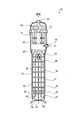
図1は、本発明の一実施例に係る管群外筒の組立方法を表す側面図、図2は、本実施例の管群外筒の組立方法を表す正面図、図3は、図1のIII-III断面図、図4は、本実施例の蒸気発生器における管群外筒の移動装置の正面図、図5は、管群外筒の移動装置の側面図、図6は、管群外筒の移動装置の平面図、図7は、昇降ジャッキの正面図、図8は、下部胴における位置決めパイプの取付状態を表す下部胴の断面図、図9は、図8のIX-IX断面図、図10は、本実施例の管群外筒の組立方法を表す概略図、図11は、本実施例の管群外筒の組立方法を表す概略図、図12は、管群外筒の位置決め方法を表す要部拡大断面図、図13は、本実施例の管群外筒の組立方法を表す概略図、図14は、本実施例の管群外筒の組立方法の手順を表すフローチャート、図15は、本実施例の蒸気発生器が適用された原子力発電プラントの概略構成図、図16は、本実施例の蒸気発生器を表す概略構成図である。
本実施例の原子炉は、軽水を原子炉冷却材及び中性子減速材として使用し、炉心全体にわたって沸騰しない高温高圧水とし、この高温高圧水を蒸気発生器に送って熱交換により蒸気を発生させ、この蒸気をタービン発電機へ送って発電する加圧水型原子炉(PWR:Pressurized Water Reactor)である。
本実施例の加圧水型原子炉を有する原子力発電プラントにおいて、図15に示すように、原子炉格納容器11内には、加圧水型原子炉12及び蒸気発生器13が格納されており、この加圧水型原子炉12と蒸気発生器13とは冷却水配管14,15を介して連結されており、冷却水配管14に加圧器16が設けられ、冷却水配管15に冷却水ポンプ15aが設けられている。この場合、減速材及び一次冷却水(冷却材)として軽水を用い、炉心部における一次冷却水の沸騰を抑制するために、一次冷却系統は加圧器16により150~160気圧程度の高圧状態を維持するように制御している。従って、加圧水型原子炉12にて、燃料(原子燃料)として低濃縮ウランまたはMOXにより一次冷却水として軽水が加熱され、高温の一次冷却水が加圧器16により所定の高圧に維持した状態で冷却水配管14を通して蒸気発生器13に送られる。この蒸気発生器13では、高圧高温の一次冷却水と二次冷却水との間で熱交換が行われ、冷やされた一次冷却水は冷却水配管15を通して加圧水型原子炉12に戻される。
蒸気発生器13は、蒸気タービン17と冷却水配管18を介して連結されており、この蒸気タービン17は高圧タービン19及び低圧タービン20を有すると共に、発電機21が接続されている。また、高圧タービン19と低圧タービン20との間には、湿分分離加熱器22が設けられており、冷却水配管18から分岐した冷却水分岐配管23が湿分分離加熱器22に連結される一方、高圧タービン19と湿分分離加熱器22は低温再熱管24により連結され、湿分分離加熱器22と低圧タービン20は高温再熱管25により連結されている。
更に、蒸気タービン17の低圧タービン20は、復水器26を有しており、この復水器26には冷却水(例えば、海水)を給排する取水管27及び排水管28が連結されている。この取水管27は、循環水ポンプ29を有し、排水管28と共に他端部が海中に配置されている。そして、この復水器26は、冷却水配管30を介して脱気器31に連結されており、この冷却水配管30に復水ポンプ32及び低圧給水加熱器33が設けられている。また、脱気器31は、冷却水配管34を介して蒸気発生器13に連結されており、この冷却水配管34には給水ポンプ35及び高圧給水加熱器36が設けられている。
従って、蒸気発生器13にて、高圧高温の一次冷却水と熱交換を行って生成された蒸気は、冷却水配管18を通して蒸気タービン17(高圧タービン19から低圧タービン20)に送られ、この蒸気により蒸気タービン17を駆動して発電機21により発電を行う。このとき、蒸気発生器13からの蒸気は、高圧タービン19を駆動した後、湿分分離加熱器22で蒸気に含まれる湿分が除去されると共に加熱されてから低圧タービン20を駆動する。そして、蒸気タービン17を駆動した蒸気は、復水器26で海水を用いて冷却されて復水となり、低圧給水加熱器33で、例えば、低圧タービン20から抽気した低圧蒸気により加熱され、脱気器31で溶存酸素や不凝結ガス(アンモニアガス)などの不純物が除去された後、高圧給水加熱器36で、例えば、高圧タービン19から抽気した高圧蒸気により加熱された後、蒸気発生器13に戻される。
このように構成された原子力発電プラントに適用される蒸気発生器13において、図16に示すように、胴部41は、密閉された中空円筒形状をなし、上部に対して下部が若干小径となっている。この胴部41は、上部胴42と下部胴43とが溶接により接合されて構成されている。この胴部41における下部胴43内には、この下部胴43の内壁面と所定間隔をもって円筒形状をなす管群外筒44が配設され、下端部が管板45の近傍まで延設されている。
管群外筒44内は、内部に所定の高さ位置に対応して複数の管支持板46が配設されており、管板45から上方に延設された複数のステーロッド47により支持されている。そして、この管群外筒44は、内部に逆U字形状をなす複数の伝熱管48からなる伝熱管群49が配設されており、各伝熱管48の端部は管板45に拡管して支持されると共に、中間部が複数の管支持板46により支持されている。この場合、管支持板46は、多数の貫通穴(図示略)が形成されており、各伝熱管48がこの貫通穴内に挿通されて支持されている。
下部胴43は、下端部に水室鏡50が固定されており、内部が隔壁51により入室52及び出室53により区画されると共に、入口ノズル54及び出口ノズル55が形成され、各伝熱管48の一端部が入室52に連通し、他端部が出室53に連通している。なお、この入口ノズル54には上述した冷却水配管14が連結される一方、出口ノズル55には冷却水配管15が連結されている。
上部胴42は、内部に給水を蒸気と熱水とに分離する気水分離器56と、この分離された蒸気の湿分を除去して乾き蒸気に近い状態とする湿分分離器57が設けられている。また、上部胴42は、伝熱管群49と気水分離器56との間に、胴部41内に二次冷却水の給水を行う給水管58が挿入される一方、天井部には蒸気出口59が形成されている。そして、胴部41は、給水管58からこの胴部41内に給水された二次冷却水を、胴部41と管群外筒44との間を流下して管板45にて上方に循環し、伝熱管群49内を上昇するときに各伝熱管48内を流れる熱水(一次冷却水)との間で熱交換を行う給水路60が設けられている。なお、給水管58には上述した冷却水配管34が連結される一方、蒸気出口59には冷却水配管18が連結されている。
従って、加圧水型原子炉12で加熱された一次冷却水が冷却水配管14を通して蒸気発生器13の入室52に送られ、多数の伝熱管48内を通って循環して出室53に至る。一方、復水器26で冷却された二次冷却水が冷却水配管34を通して蒸気発生器13の給水管58に送られ、胴部41内の給水路60を通って伝熱管48内を流れる熱水(一次冷却水)と熱交換を行う。即ち、胴部41内で、高圧高温の一次冷却水と二次冷却水との間で熱交換が行われ、冷やされた一次冷却水は出室53から冷却水配管15を通して加圧水型原子炉12に戻される。一方、高圧高温の一次冷却水と熱交換を行った二次冷却水は、胴部41内を上昇し、気水分離器56で蒸気と熱水とに分離され、湿分分離器57でこの蒸気の湿分を除去してから、冷却水配管18を通して蒸気タービン17に送られる。
このように構成された蒸気発生器13にて、図1乃至図3に示すように、下部胴43は、円筒形状をなし、上部が所定角度で上方に広角するような拡径部43aが一体に形成され、下端部に管板45が溶接により固定されている。そして、この下部胴43は、床面に設置された2つの支持装置61,62の支持ローラ61a,62aにより横倒しに支持され、且つ、周方向に回転自在となっている。
一方、管群外筒44は、円筒形状をなし、外径が下部胴43の内径より小径となっており、この下部胴43内に所定隙間をもって挿入可能となっている。また、この管群外筒44は、薄肉の板材により形成されていることから、内周面に円盤リング形状をなす補強リング63が長手方向に所定間隔で固定(例えば、溶接)されている。そして、この管群外筒44は、図示しないクレーンからの吊り部材64により横倒しに吊り下げ支持され、下端部側から下部胴43の上端部側に挿入可能となっている。また、管群外筒44は、その下部に3つの移動装置65,66,67が長手方向に所定間隔で着脱自在に装着されており、この管群外筒44が下部胴43内に挿入された後、この第1、第2、第3移動装置65,66,67により所定の接合位置まで移動可能となっている。
管群外筒44は、上述したように、内周面に複数の補強リング63が固定されていることから、クレーンからの吊り部材64により吊り下げ支持する位置は、この補強リング63が固定された位置となっている。また、第1、第2、第3移動装置65,66,67により支持する位置も、この補強リング63が固定された位置となっている。即ち、管群外筒44は、下部胴43への組付後に、内部に複数の管支持板46(図16参照)が長手方向に所定間隔で取付けられることから、この管支持板46の取付位置に複数の取付用開口44aが形成されると共に、管群外筒44に対して管支持板46の位置を調整するジャッキ組立体(図示略)の取付板44b(図7参照)が取付けられる。ここでは、管群外筒44は、横倒しに支持された下部に位置する取付用開口44aに第1、第2、第3移動装置65,66,67が装着されている。
この第1、第2、第3移動装置65,66,67は、それぞれ2つで1組をなし、横倒しに支持された管群外筒44の鉛直方向の下部に周方向に並んで配置され、各取付用開口44aに装着されている。そして、この各移動装置65,66,67にて、2つの装置の間に第1、第2、第3昇降ジャッキ68,69,70が着脱自在となっている。
ここで、第1、第2、第3移動装置65,66,67について詳細に説明するが、各移動装置65,66,67は、同様の構成をなしていることから、第1移動装置65についてのみ説明する。
図4乃至図6に示すように、下部胴43の内側に所定隙間をもって管群外筒44が位置するとき、この管群外筒44に形成された取付用開口44aに対応して補強リング63が固定され、且つ、補強リング63に切欠部63aが形成されている。そして、第1移動装置65は、この補強リング63の切欠部63aに固定された一対の取付板101に対応して着脱自在に取付けられている。
この第1移動装置65は、管群外筒44に固定された補強リング63の取付板101に対して着脱自在な架台102と、この架台102を介して管群外筒44を昇降自在な第1昇降ジャッキ68と、架台102に対して着脱自在なチルタンク(台車)103と、架台102に対してチルタンク103の走行方向を転換する転換装置104とから構成されている。
即ち、補強リング63は、外周部に複数の切欠部63aが形成されており、横倒し状態にある管群外筒の下部に位置する切欠部63aに対応して、この補強リング63を両面から挟持するように一対の取付板101が溶接により固定されている。そして、この一対の取付板101は、切欠部63aに対応して3つの取付孔101aが形成されている。
第1移動装置65において、取付プレート111は、一対の取付板101の間に挿入され、3つの取付ボルト112が取付孔101a及び取付プレート111の取付孔(図示略)を貫通して締結されることで、補強リング63、つまり、管群外筒44に固定されている。取付プレート111は、水平な支持プレート113が溶接により固定されており、支持プレート113の下面に補強プレート114が固定ボルト115により固定されている。そして、補強プレート114は、下面部にチルタンク103の取付プレート116が密着し、複数のボルト(逆転防止部材)117により着脱自在に固定されている。このチルタンク103は、複数の車輪118を有しており、下部胴43の内壁面上を周方向または長手方向(軸方向)に走行自在となっている。また、支持プレート113及び補強プレート114は、鉛直方向に貫通するように軸受部119が固定され、チルタンク103の取付プレート116から上方に延出する一体の支持軸120がこの軸受部119に回動自在に支持され、この支持軸120の上端部に2つの操作ハンドル121が装着されている。
この場合、取付プレート111及び支持プレート113などにより架台102が構成される。また、軸受部119、支持軸120、操作ハンドル121により転換装置104が構成される。
また、第1昇降ジャッキ68は、図7に示すように、ジャッキ本体131と、支持板132と、2つの脚部133を有している。このジャッキ本体131は、下部が支持板132に固定され、上部に上下に伸縮可能な駆動ロッド131aを有している。そして、支持板132は、下部固定された2つの脚部133が管群外筒44の取付用開口44aに固定された取付板44bのねじ孔44cに貫通している。
従って、図4乃至図7に示すように、管群外筒44は、複数の取付用開口44aが形成されると共に補強リング63が固定されており、また、複数の取付用開口44aのうちの一部に取付板44bが固定されている。補強リング63は、複数の切欠部63aが形成されていると共に、この切欠部63aに対応して取付板101が固定されている。
そして、第1移動装置65は、取付プレート111を取付板101の間に挿入し、3つの取付ボルト112により締結することで、取付板101、つまり、補強リング63を介して管群外筒44に固定することができる。一方、第1昇降ジャッキ68は、2つの脚部133を管群外筒44の取付用開口44aに固定された取付板44bのねじ孔44cに挿入することで、管群外筒44に装着することができる。
そして、第1昇降ジャッキ68を作動して駆動ロッド131aを伸張することで、下部胴43に対して、補強リング63(切欠部63a)を介して管群外筒44を上昇させることができる。この状態で、複数のボルト117を緩め、操作ハンドル121を90度回動することで、チルタンク103の向きを90度変更し、その走行方向を下部胴43の長手方向と周方向との間で転換することができる。
また、下部胴43は、管群外筒44を内部に挿入して所定の位置に接合するとき、その位置を位置決め可能となっている。図8及び図9に示すように、下部胴43は、その長手方向の下部に4つの点検用開口部43bが周方向等間隔(90度間隔)に形成されており、この各点検用開口部43bに位置決めパイプ71,72が挿入されている。この位置決めパイプ71は、下部胴43の外径より長い長さを有し、基端部にフランジ71aが形成されると共に、両端部に吊り用孔71bが形成されている。一方、位置決めパイプ72は、下部胴43の外径より短く、半径の1/2程度の長さを有し、基端部にフランジ72aが形成されると共に、両端部に吊り用孔72bが形成されている。
そして、位置決めパイプ71は、下部胴43に形成された2つの点検用開口部43bに貫通させ、フランジ71aが下部胴43の外周面に当接した位置で、先端部にフランジ73を固定することで抜け止めがなされ、固定ボルト74により下部胴43に固定する。一方、位置決めパイプ72は、2本設置し、下部胴43に形成された残り2つの点検用開口部43bに貫通させ、フランジ72aが下部胴43の外周面に当接した位置で、固定ボルト75により下部胴43に固定する。
一方、管群外筒44は、その長手方向の下部に下部胴43に形成された4つの点検用開口部43bに対応して4つの点検用切欠部44dが周方向等間隔(90度間隔)に形成されている。従って、下部胴43内に挿入された管群外筒44を移動装置65,66,67により移動するとき、各点検用開口部43bを各位置決めパイプ71,72に嵌合することで、下部胴43に対する管群外筒44の長手方向及び周方向の位置決めを行うことができる。
ここで、上述した管群外筒44の組立方法並びに蒸気発生器13の組立方法について、詳細に説明する。
本実施例の管群外筒44の組立方法は、図1に示すように、伝熱管群49が支持される管群外筒44を胴部41を構成する下部胴43内に組み付ける方法であって、横倒しに支持された下部胴43にその上部側から横倒しに支持された管群外筒44を挿入し、管群外筒44を所定の挿入位置で下部胴43に固定するものである。
このとき、管群外筒44は、外周部に着脱自在に装着された3つの移動装置65,66,67により下部胴43の内周面を所定の挿入位置まで移動するようにしている。また、管群外筒44は、内側に補強リング63が長手方向に所定間隔で複数装着されており、移動装置65,66,67が管群外筒44における補強リング63に対応する位置を支持して移動するようにしている。また、管群外筒44は、下部の切欠部44dが下部胴43の下部の装着された位置決めパイプ71,72に嵌合することで、位置決めがなされるようにしている。
また、本実施例の蒸気発生器13の組立方法は、横倒しに支持された下部胴43に対してその上部側から横倒しに支持した管群外筒44を挿入する管群外筒挿入工程と、下部胴43内の管群外筒44に対して管支持板46及び伝熱管48を組み付ける工程と、内部に管群外筒44及び伝熱管群49が収容されて横倒しに支持された下部胴43に対して内部に湿分分離器57及び気水分離器56が収容された上部胴42を接合する胴部接合工程と、を有している。
以下、図14のフローチャートに基づいて説明する。本実施例の管群外筒44の組立方法並びに蒸気発生器の組立方法において、図14に示すように、まず、ステップS11にて、下部胴43を横倒しとして支持装置61,62により支持する。続いて、ステップS12にて、管群外筒44を横倒しとしてクレーンから吊り下げられた吊り部材64により支持する。そして、ステップS13にて、横倒し支持された管群外筒44の側部、つまり、図1にて下部に3つの移動装置65,66,67(昇降ジャッキ68,69,70)を装着する。また、ステップS14にて、下部胴43に位置決めパイプ71,72を装着する。
このように準備が完了すると、ステップS15にて、図1に示すように、クレーンを作動して吊り部材64により管群外筒44を吊り上げ支持しながら、下端部を下部胴43内へ挿入する。管群外筒44の下端部が下部胴43内に挿入されると、管群外筒44は、下端部が第1移動装置65を介して下部胴43に支持されることから、ステップS16にて、吊り部材64による管群外筒44の支持位置を、図10に表す二点鎖線の位置から実線の位置に変更する。
そして、クレーンを作動して吊り部材64により管群外筒44を吊り上げ支持しながら、この管群外筒44を下部胴43内へ挿入していくと、図10に示すように、管群外筒44は、下端部が第1移動装置65により下部胴43に支持されると共に、中間部が第2移動装置66により下部胴43に支持される。更に、クレーンを作動して吊り部材64により管群外筒44を吊り上げ支持しながら、この管群外筒44を下部胴43内へ挿入していくと、管群外筒44は、図11に示すように、下端部が第1移動装置65により下部胴43に支持され、中間部が第2移動装置66により下部胴43に支持され、上端部が第3移動装置67により下部胴43に支持される。ステップS17では、管群外筒44は、3つの移動装置65,66,67により支持されることから、クレーンの吊り部材64による支持を解除する。
そして、図12に示すように、管群外筒44は、下部胴43に対する正規の組付位置から所定距離手前にある。そのため、ステップS18にて、作業者は、管群外筒44の補強板63にクランプ81を固定し、クランプ81と下部胴43のパイプ71,72との間にチェーン82を掛止し、レバーブロック(登録商標)(トルクレンチ)83を装着する。そして、ステップS19にて、作業者は、レバーブロック83を操作することで、チェーン82を牽引して巻き取ることで、管群外筒44を下部胴43側に移動する。
この作業に平行して、ステップS20では、管群外筒44の周方向の調整を行う。各移動装置65,66,67は、チルタンク103の走行可能方向が下部胴43の長手方向であることから、転換装置104を用いてチルタンク103を90度回動し、このチルタンク103の走行可能方向を下部胴43の周方向とする。そして、各移動装置65,66,67により管群外筒44を下部胴43の周方向に移動することで、下部胴43に対してこの管群外筒44の周方向位置を調整する。この場合、支持装置61,62により下部胴43を回動することで、管群外筒44との相対位置を変更することで、周方向位置を調整してもよい。
管群外筒44の周方向調整が完了したら、チルタンク103の方向転換を行う。即ち、前述と同様に、転換装置104を用いてチルタンク103を90度回動し、このチルタンク103の走行可能方向を下部胴43の長手方向とする。そして、ステップS21にて、作業者は、引き続き、レバーブロック81を操作することで、チェーン84を牽引して巻き取ることで、管群外筒44を下部胴43側に移動する。このとき、複数のレバーブロック83を操作することで、管群外筒44における周方向の複数位置を牽引する。
そして、ステップS22にて、管群外筒44が下部胴43における正規の組付位置に近づくと、支持装置61,62、チルタンク103、昇降ジャッキ68,69,70などを用いて管群外筒44の最終的に位置調整を行い、図13に示すように、管群外筒44をその切欠部44dが下部胴43に固定されている位置決めパイプ71,72に嵌合するまで移動する。そして、ステップS23にて、管群外筒44及び下部胴43から、クランプ81、チェーン82、レバーブロック83、各移動装置65,66,67(各昇降ジャッキ68,69,70)位置決めパイプ71,72などを取り外す。
管群外筒44が下部胴43における正規の組付位置に移動すると、ステップS24にて、管群外筒44を下部胴43に固定する。即ち、管群外筒44と下部胴43との間にボルトなどを組み付けることで、下部胴43に対して管群外筒44を固定する。その後、ステップS25にて、管群外筒44から補強リング63などを取り外す。
このように管群外筒44を下部胴43に組み付ける作業が完了したら、下部胴43内の管群外筒44に対して複数の管支持板46を挿入して固定した後、複数の伝熱管48を組み付けていく。一方、上部胴42内に湿分分離器57や気水分離器56などを収容した後、内部に管群外筒44及び伝熱管群49などが収容されて横倒しに支持された下部胴43に対して、内部に湿分分離器57及び気水分離器56などが収容された上部胴42を接合する。このようにして蒸気発生器13が組み付けられる。
このように本実施例の管群外筒の組立方法にあっては、伝熱管群49が支持される管群外筒44を胴部41内に組み付ける方法にて、胴部41を上部胴42と下部胴43とにより構成し、横倒しに支持された下部胴43にその上部側から横倒しに支持された管群外筒44を挿入し、管群外筒44を所定の挿入位置まで移動して下部胴43に固定するようにしている。
従って、横倒しに支持された下部胴43に、横倒しに支持された管群外筒44を所定の挿入位置まで挿入して固定することで、下部胴43や管群外筒44を鉛直方向に立てて支持する必要はなく、屋根の高い組立工場の建屋を不要として製造コストを低減することができる。また、管群外筒44の吊り上げを不要とすることで、管群外筒44を下部胴43内に挿入するときに管群外筒44の揺れを防止することができ、その結果、組立作業における作業性を向上することができる。
また、本実施例の管群外筒の組立方法では、管群外筒44をその外周部に着脱自在に装着された複数の移動装置65,66,67により下部胴43の内周面を所定の挿入位置まで移動するようにしている。従って、各移動装置65,66,67により管群外筒44を下部胴43内に適正に移動することができ、管群外筒の吊り上げを不要とし、横倒しに支持した状態で移動することで、管群外筒44の揺れを防止することができ、組立作業における作業性を向上することができる。
また、本実施例の管群外筒の組立方法では、管群外筒44の内側に複数の補強リング63を長手方向に所定間隔で装着し、各移動装置65,66,67が管群外筒44における補強リング63に対応する位置を支持している。従って、各移動装置65,66,67が管群外筒44における補強リング63に対応する位置を支持して移動することで、管群外筒44の変形を防止することができる。
また、本実施例の管群外筒の組立方法では、管群外筒44の下部に切欠部44dを形成し、この切欠部44dが下部胴43の下部の装着された位置決めパイプ71,72に嵌合することで、位置決めを行っている。従って、管群外筒44の切欠部44dが下部胴43の位置決めパイプ71,72に嵌合して位置決めを行うことで、下部胴43に対する管群外筒44の高精度な位置決めを行うことができる。
また、本実施例の蒸気発生器の組立方法にあっては、横倒しに支持された下部胴43に対してその上部側から横倒しに支持した管群外筒44を挿入する管群外筒挿入工程と、下部胴43内の管群外筒44に対して管支持板46及び伝熱管48を組み付ける工程と、内部に管群外筒44及び伝熱管群49が収容されて横倒しに支持された下部胴43に対して内部に湿分分離器57及び気水分離器56が収容された上部胴42を接合する胴部接合工程とを設けている。
従って、下部胴43、管群外筒44、上部胴42などを横倒しに支持した状態で、各種の組付作業を行うことで、屋根の高い組立工場の建屋を不要として製造コストを低減することができると共に、部材の吊り上げを不要として揺れ防止することができ、その結果、組立作業における作業性を向上することができる。
また、本実施例の管群外筒の移動装置にあっては、横倒しに支持された下部胴43にその上部側から横倒しに支持された管群外筒44を挿入するときに、管群外筒44を移動可能な移動装置65,66,67にて、管群外筒44における長手方向の前後に着脱自在な架台102と、架台102を介して管群外筒44を昇降自在な昇降ジャッキ68,69,70と、架台102に着脱自在なチルタンク103と、架台102に対してチルタンク103の走行方向を転換する転換装置104とを設けている。
従って、管群外筒44を下部胴43内に挿入するとき、各移動装置65,66,67により管群外筒44を下部胴43内に容易に移動し、このとき、この各移動装置65,66,67により管群外筒44の周方向位置の調整を行うことができ、管群外筒44の高精度な装着を可能とすることができる。
なお、上述した実施例では、管群外筒44を下部胴43内に挿入する装置として、クレーンと3つの移動装置65,66,67を用いたが、この装置に限定されるものではない。例えば、クレーンに代えて管群外筒44を下部胴43内に押し込む油圧シリンダなどを適用してもよい。また、移動装置65,66,67の個数は、6個に限るものではなく、管群外筒44の大きさや重さなどにより適宜設定すればよいものである。
11 原子炉格納容器
12 加圧水型原子炉
13 蒸気発生器
17 蒸気タービン
19 高圧タービン
20 低圧タービン
21 発電機
41 胴部
42 上部胴
43 下部胴
44 管群外筒
44a 取付用開口
44b 取付板
44c ねじ孔
44d 切欠部
45 管板
46 管支持板
49 伝熱管群
63 補強リング
63a 切欠部
64 吊り部材
65,66,67 移動装置
68,69,70 昇降ジャッキ
101 取付板
102 架台
103 チルタンク(台車)
104 転換装置
12 加圧水型原子炉
13 蒸気発生器
17 蒸気タービン
19 高圧タービン
20 低圧タービン
21 発電機
41 胴部
42 上部胴
43 下部胴
44 管群外筒
44a 取付用開口
44b 取付板
44c ねじ孔
44d 切欠部
45 管板
46 管支持板
49 伝熱管群
63 補強リング
63a 切欠部
64 吊り部材
65,66,67 移動装置
68,69,70 昇降ジャッキ
101 取付板
102 架台
103 チルタンク(台車)
104 転換装置
Claims (6)
- 伝熱管群が支持される管群外筒を胴部内に組み付ける管群外筒の組立方法であって、
前記胴部を上部胴と下部胴とにより構成し、
横倒しに支持された下部胴にその上部側から横倒しに支持された管群外筒を挿入し、
前記管群外筒を所定の挿入位置で前記下部胴に固定する、
ことを特徴とする管群外筒の組立方法。 - 前記管群外筒は、外周部に着脱自在に装着された複数の移動装置により前記下部胴の内周面を所定の挿入位置まで移動することを特徴とする請求項1に記載の管群外筒の組立方法。
- 前記管群外筒は、内側に補強リングが長手方向に所定間隔で複数装着されており、移動装置が前記管群外筒における前記補強リングに対応する位置を支持して移動することを特徴とする請求項2に記載の管群外筒の組立方法。
- 前記管群外筒は、下部の切欠部が前記下部胴の下部の装着された位置決めパイプに嵌合することで、位置決めがなされることを特徴とする請求項1から3のいずれか一つに記載の管群外筒の組立方法。
- 横倒しに支持された下部胴に対してその上部側から横倒しに支持した管群外筒を挿入する管群外筒挿入工程と、
前記下部胴内の管群外筒に対して管支持板及び伝熱管を組み付ける工程と、
内部に管群外筒及び伝熱管群が収容されて横倒しに支持された下部胴に対して内部に湿分分離器及び気水分離器が収容された上部胴を接合する胴部接合工程と、
を有することを特徴とする蒸気発生器の組立方法。 - 横倒しに支持された下部胴にその上部側から横倒しに支持された管群外筒を挿入するときに前記管群外筒を移動可能な移動装置であって、
前記管群外筒における長手方向の前後に着脱自在な架台と、
前記架台を介して前記管群外筒を昇降自在な昇降装置と、
前記架台に着脱自在な台車と、
前記架台に対して台車の走行方向を転換する転換装置と、
を備えることを特徴とする管群外筒の移動装置。
Applications Claiming Priority (2)
| Application Number | Priority Date | Filing Date | Title |
|---|---|---|---|
| JP2011025357A JP5871472B2 (ja) | 2011-02-08 | 2011-02-08 | 管群外筒の組立方法及び蒸気発生器の組立方法、管群外筒の移動装置 |
| JP2011-025357 | 2011-02-08 |
Publications (1)
| Publication Number | Publication Date |
|---|---|
| WO2012108272A1 true WO2012108272A1 (ja) | 2012-08-16 |
Family
ID=46638489
Family Applications (1)
| Application Number | Title | Priority Date | Filing Date |
|---|---|---|---|
| PCT/JP2012/051675 Ceased WO2012108272A1 (ja) | 2011-02-08 | 2012-01-26 | 管群外筒の組立方法及び蒸気発生器の組立方法、管群外筒の移動装置 |
Country Status (2)
| Country | Link |
|---|---|
| JP (1) | JP5871472B2 (ja) |
| WO (1) | WO2012108272A1 (ja) |
Cited By (1)
| Publication number | Priority date | Publication date | Assignee | Title |
|---|---|---|---|---|
| CN110806141A (zh) * | 2019-11-11 | 2020-02-18 | 哈尔滨工业大学 | 一种超长管束与壳体的套装方法 |
Families Citing this family (1)
| Publication number | Priority date | Publication date | Assignee | Title |
|---|---|---|---|---|
| WO2015022943A1 (ja) | 2013-08-13 | 2015-02-19 | 株式会社Ihi | 円筒状容器製造用支持装置 |
Citations (5)
| Publication number | Priority date | Publication date | Assignee | Title |
|---|---|---|---|---|
| JPS58160061A (ja) * | 1981-12-11 | 1983-09-22 | フラマト−ム・エ・コムパニ− | 蒸気発生器の管板に管束を固定するための工具用の支持兼移動装置 |
| JPH09280771A (ja) * | 1996-04-10 | 1997-10-31 | Mitsubishi Heavy Ind Ltd | 熱交換器及びその製造方法 |
| JPH1047874A (ja) * | 1996-08-07 | 1998-02-20 | Toshiba Corp | 熱交換器の熱交換用チューブ組立て装置および組立て方法 |
| JP2009168405A (ja) * | 2008-01-18 | 2009-07-30 | Mitsubishi Heavy Ind Ltd | 蒸気発生器の製造方法および伝熱管挿入治具 |
| JP2011226693A (ja) * | 2010-04-19 | 2011-11-10 | Ihi Corp | 管支持板取付装置 |
Family Cites Families (1)
| Publication number | Priority date | Publication date | Assignee | Title |
|---|---|---|---|---|
| FR2562996B1 (fr) * | 1984-04-11 | 1986-06-20 | Framatome Sa | Echangeur de chaleur comportant un faisceau de tubes dispose dans une enveloppe de faisceau cylindrique maintenue radialement a l'interieur d'une enveloppe cylindrique externe |
-
2011
- 2011-02-08 JP JP2011025357A patent/JP5871472B2/ja active Active
-
2012
- 2012-01-26 WO PCT/JP2012/051675 patent/WO2012108272A1/ja not_active Ceased
Patent Citations (5)
| Publication number | Priority date | Publication date | Assignee | Title |
|---|---|---|---|---|
| JPS58160061A (ja) * | 1981-12-11 | 1983-09-22 | フラマト−ム・エ・コムパニ− | 蒸気発生器の管板に管束を固定するための工具用の支持兼移動装置 |
| JPH09280771A (ja) * | 1996-04-10 | 1997-10-31 | Mitsubishi Heavy Ind Ltd | 熱交換器及びその製造方法 |
| JPH1047874A (ja) * | 1996-08-07 | 1998-02-20 | Toshiba Corp | 熱交換器の熱交換用チューブ組立て装置および組立て方法 |
| JP2009168405A (ja) * | 2008-01-18 | 2009-07-30 | Mitsubishi Heavy Ind Ltd | 蒸気発生器の製造方法および伝熱管挿入治具 |
| JP2011226693A (ja) * | 2010-04-19 | 2011-11-10 | Ihi Corp | 管支持板取付装置 |
Cited By (2)
| Publication number | Priority date | Publication date | Assignee | Title |
|---|---|---|---|---|
| CN110806141A (zh) * | 2019-11-11 | 2020-02-18 | 哈尔滨工业大学 | 一种超长管束与壳体的套装方法 |
| CN110806141B (zh) * | 2019-11-11 | 2020-11-27 | 哈尔滨工业大学 | 一种超长管束与壳体的套装方法 |
Also Published As
| Publication number | Publication date |
|---|---|
| JP2012163292A (ja) | 2012-08-30 |
| JP5871472B2 (ja) | 2016-03-01 |
Similar Documents
| Publication | Publication Date | Title |
|---|---|---|
| EP2681500B1 (en) | Nuclear steam generator support and alignment structure | |
| US11935663B2 (en) | Control rod drive system for nuclear reactor | |
| WO2012105410A1 (ja) | 締結弛緩装置 | |
| JP5172144B2 (ja) | 熱交換器の水室に対して作業を行う装置及び方法 | |
| EP2671678A1 (en) | Bolt tensioner | |
| US8711998B2 (en) | Cooling structure and cooling method for control rod drive mechanism and nuclear reactor | |
| US20130336439A1 (en) | Neutron flux detector guiding apparatus | |
| JP5871472B2 (ja) | 管群外筒の組立方法及び蒸気発生器の組立方法、管群外筒の移動装置 | |
| KR101705476B1 (ko) | 원자로 보수 장치의 설치 장치 및 방법 | |
| CA2907067C (en) | Upper vessel transport | |
| JP2007147163A (ja) | 蒸気発生器及び蒸気発生器における冷却水の流動抵抗調整方法 | |
| JP5955173B2 (ja) | 蒸気発生器解体方法 | |
| EP2641680A1 (en) | Hole drilling device, and method | |
| CN210667819U (zh) | 一种适用于双层套管结构核蒸汽供应系统的反应堆本体结构 | |
| WO2012063731A1 (ja) | 蒸気発生器、蒸気発生器の組立方法、気水分離器の移動装置 | |
| JP6550244B2 (ja) | 駆動軸の取扱工具 | |
| JP2014145590A (ja) | 原子炉補修監視装置及び原子炉補修方法 | |
| JP5214137B2 (ja) | 沸騰水型原子炉 | |
| JP2013040823A (ja) | 原子炉容器の管台処理装置 | |
| JP5863495B2 (ja) | 蒸気発生器の製造方法 | |
| JP2005082313A (ja) | 板状重量構造物の格納方法 | |
| JP2016133458A (ja) | ボルト用架台 |
Legal Events
| Date | Code | Title | Description |
|---|---|---|---|
| 121 | Ep: the epo has been informed by wipo that ep was designated in this application |
Ref document number: 12744285 Country of ref document: EP Kind code of ref document: A1 |
|
| NENP | Non-entry into the national phase |
Ref country code: DE |
|
| 122 | Ep: pct application non-entry in european phase |
Ref document number: 12744285 Country of ref document: EP Kind code of ref document: A1 |