WO2012108102A1 - 結晶性ポリマー微孔性膜及びその製造方法、並びに濾過用フィルタ - Google Patents
結晶性ポリマー微孔性膜及びその製造方法、並びに濾過用フィルタ Download PDFInfo
- Publication number
- WO2012108102A1 WO2012108102A1 PCT/JP2011/079147 JP2011079147W WO2012108102A1 WO 2012108102 A1 WO2012108102 A1 WO 2012108102A1 JP 2011079147 W JP2011079147 W JP 2011079147W WO 2012108102 A1 WO2012108102 A1 WO 2012108102A1
- Authority
- WO
- WIPO (PCT)
- Prior art keywords
- crystalline polymer
- microporous membrane
- group
- polymer microporous
- film
- Prior art date
- Legal status (The legal status is an assumption and is not a legal conclusion. Google has not performed a legal analysis and makes no representation as to the accuracy of the status listed.)
- Ceased
Links
Images




Classifications
-
- B—PERFORMING OPERATIONS; TRANSPORTING
- B01—PHYSICAL OR CHEMICAL PROCESSES OR APPARATUS IN GENERAL
- B01D—SEPARATION
- B01D71/00—Semi-permeable membranes for separation processes or apparatus characterised by the material; Manufacturing processes specially adapted therefor
- B01D71/06—Organic material
- B01D71/30—Polyalkenyl halides
- B01D71/32—Polyalkenyl halides containing fluorine atoms
- B01D71/36—Polytetrafluoroethylene
-
- B—PERFORMING OPERATIONS; TRANSPORTING
- B01—PHYSICAL OR CHEMICAL PROCESSES OR APPARATUS IN GENERAL
- B01D—SEPARATION
- B01D63/00—Apparatus in general for separation processes using semi-permeable membranes
- B01D63/14—Pleat-type membrane modules
-
- B—PERFORMING OPERATIONS; TRANSPORTING
- B01—PHYSICAL OR CHEMICAL PROCESSES OR APPARATUS IN GENERAL
- B01D—SEPARATION
- B01D67/00—Processes specially adapted for manufacturing semi-permeable membranes for separation processes or apparatus
- B01D67/0081—After-treatment of organic or inorganic membranes
- B01D67/0088—Physical treatment with compounds, e.g. swelling, coating or impregnation
-
- B—PERFORMING OPERATIONS; TRANSPORTING
- B01—PHYSICAL OR CHEMICAL PROCESSES OR APPARATUS IN GENERAL
- B01D—SEPARATION
- B01D2325/00—Details relating to properties of membranes
- B01D2325/02—Details relating to pores or porosity of the membranes
- B01D2325/021—Pore shapes
- B01D2325/0212—Symmetric or isoporous membranes
Definitions
- the present invention uses a crystalline polymer microporous membrane having high filtration efficiency used for microfiltration of gas, liquid, etc., a method for producing a crystalline polymer microporous membrane, and the crystalline polymer microporous membrane.
- the present invention relates to a filter for filtration.
- Microporous membranes have been known for a long time and are widely used in filtration filters and the like.
- Examples of such a microporous membrane include those manufactured using cellulose ester as a raw material (see Patent Document 1 etc.), those manufactured using aliphatic polyamide as a raw material (see Patent Document 2 etc.), and polyfluorocarbon as a raw material. And the like (see Patent Document 3 etc.) and those made of polypropylene (see Patent Document 4 etc.).
- These microporous membranes are used for filtration and sterilization of electronic industry cleaning water, semiconductor manufacturing chemicals, pharmaceutical water, pharmaceutical manufacturing process water, food water, etc.
- a highly reliable microporous membrane is attracting attention from the viewpoint of particle trapping.
- a microporous film made of a crystalline polymer has excellent chemical resistance
- a microporous film made from polytetrafluoroethylene (PTFE) has excellent heat resistance and chemical resistance. The demand growth is remarkable.
- PTFE polytetrafluoroethylene
- the filterable amount per unit area of the microporous membrane is small (that is, the filtration life is short). For this reason, when industrially used, in order to increase the membrane area, it is necessary to use many filtration units in parallel, and from the viewpoint of cost reduction of the filtration process, the filtration life is increased. Is needed.
- an asymmetric pore membrane has been proposed in which the average pore diameter gradually decreases from the inlet side toward the outlet side.
- Patent Document 5 a microporous membrane of crystalline polymer in which the average pore size on the surface of the membrane is larger than the average pore size on the back surface and the average pore size continuously changes from the front surface to the back surface.
- Patent Document 5 a microporous membrane of crystalline polymer in which the average pore size on the surface of the membrane is larger than the average pore size on the back surface and the average pore size continuously changes from the front surface to the back surface.
- a hydrophilic treatment method for a crystalline polymer microporous membrane having asymmetric pores for example, in Patent Document 6, the exposed surface of the crystalline polymer microporous membrane having an asymmetric pore structure is treated with hydrogen peroxide or a water-soluble solvent. It has been proposed to perform a hydrophilic treatment by impregnation with an aqueous solution of the above, laser irradiation, chemical etching and the like.
- a crystalline polymer microporous membrane having asymmetric pores has a heated surface, a non-heated surface, and the inside thereof, and the degree of crystallinity of the crystalline polymer at each site is different.
- the entire membrane cannot be uniformly hydrophilized, and if an attempt is made to perform the hydrophilization treatment, it is necessary to perform the hydrophilization treatment several times for each condition depending on the degree of crystallinity. It ’s bad. Further, the hydrophilicity of the produced hydrophilic treatment film was not sufficiently satisfactory. Furthermore, in the method of performing hydrophilic treatment by irradiating with an ultraviolet laser and an ArF laser, there is a problem that the film is damaged by the irradiation with the ultraviolet laser and the ArF laser, and the film strength is deteriorated.
- a hydrophilization treatment method for the crystalline polymer microporous membrane a cationic polymerizable monomer and a cationic polymerization initiator are included, and the cationic polymerizable monomer is polymerized to form at least a part of the surface of the porous membrane.
- a modification method has been proposed, and optionally, a functional monomer containing a quaternary ammonium salt or the like has been proposed (see Patent Document 7).
- Patent Document 7 a functional monomer containing a quaternary ammonium salt or the like has been proposed.
- this proposal has a problem that the filtration flow rate and the filtration life of the porous membrane cannot be improved to a sufficiently satisfactory level.
- the present invention is a crystalline polymer microporous membrane having excellent water resistance and ion adsorption capacity, high hydrophilicity, long filtration life, and excellent permeation flow rate, and the crystalline polymer microporous membrane. It is an object of the present invention to provide a method for producing a crystalline polymer microporous membrane that can be well produced, and a filter for filtration using the crystalline polymer microporous membrane.
- Means for solving the problems are as follows. That is, ⁇ 1> A crystalline polymer microporous membrane having an asymmetric pore structure, At least a part of the exposed surface of the crystalline polymeric microporous membrane is coated with a radical polymer obtained by polymerizing a composition containing a radical polymerizable monomer, and at least a part of the radical polymer has an ion exchange group. And a functional compound containing at least one of a chelate group, and the radical polymerizable monomer is at least one selected from acrylate, methacrylate, acrylamide, acrylic acid and derivatives thereof A crystalline polymer microporous membrane.
- ⁇ 2> The crystalline polymer microporosity according to ⁇ 1>, wherein the radical polymerizable monomer has at least one of a carboxyl group, an amino group, a hydroxyl group, an epoxy group, an acrylamide group, an isocyanate group, and an acid chloride group. It is a membrane.
- the functional compound is a compound having a reactive group with a radical polymer.
- the average hole diameter in the first surface of the two exposed surfaces is larger than the average hole diameter in the second surface located on the opposite side of the first surface, and the first surface from the first surface
- a film obtained by heating one surface of a film containing a crystalline polymer constituting a crystalline polymer microporous film and stretching a semi-baked film imparted with a temperature gradient in the thickness direction of the film ⁇ 4> is a crystalline polymer microporous film.
- ⁇ 6> The crystalline polymer microporous film according to any one of ⁇ 4> to ⁇ 5>, wherein the second surface is a heating surface.
- the crystalline polymer is polytetrafluoroethylene, polyvinylidene fluoride, tetrafluoroethylene / perfluoroalkyl vinyl ether copolymer, tetrafluoroethylene / hexafluoropropylene copolymer, tetrafluoroethylene / ethylene copolymer, polyfluoride.
- Vinylidene fluoride polychlorotrifluoroethylene, chlorotrifluoroethylene-ethylene copolymer, polyethylene, polypropylene, nylon, polyacetal, polybutylene terephthalate, polyethylene terephthalate, syndiotactic polystyrene, polyphenylene sulfide, polyether ether ketone, wholly aromatic ⁇ 1> to ⁇ 7>, which is at least one selected from aromatic polyamides, wholly aromatic polyesters, and polyether nitriles
- the crystalline polymer microporous membrane according to any one of the above.
- ⁇ 9> The crystalline polymer microporous membrane according to any one of ⁇ 1> to ⁇ 7>, wherein the crystalline polymer is polytetrafluoroethylene.
- An addition reaction treatment step of subjecting a part of the radical polymer to an addition reaction with a functional compound containing at least one of an ion exchange group and a chelate group;
- the radically polymerizable monomer is at least one selected from acrylate, methacrylate, acrylamide, acrylic acid and derivatives thereof.
- ⁇ 11> An asymmetric heating step of heating one surface of a film made of a crystalline polymer to form a semi-baked film having a temperature gradient in the thickness direction of the film;
- ⁇ 12> The radical polymerizable monomer according to any one of ⁇ 10> to ⁇ 11>, wherein the radical polymerizable monomer includes at least one of a carboxyl group, an amino group, a hydroxyl group, an epoxy group, an acrylamide group, an isocyanate group, and an acid chloride group.
- a filtration filter comprising the crystalline polymer microporous membrane according to any one of ⁇ 1> to ⁇ 9>.
- the above-described problems can be achieved by solving the above-mentioned problems, water resistance, ion adsorption ability, high hydrophilicity, long filtration life, and excellent permeation flow rate.
- Polymeric microporous membrane, crystalline polymer microporous membrane production method capable of efficiently producing the crystalline polymer microporous membrane, and filtration filter using the crystalline polymer microporous membrane can be provided.
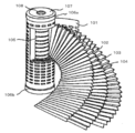
- FIG. 1 is a diagram illustrating a structure of a general pleated filter element before being assembled in a housing.
- FIG. 2 is a view showing the structure of a general filter element before being assembled into the housing of the capsule filter cartridge.
- FIG. 3 is a view showing the structure of a general capsule filter cartridge integrated with a housing.
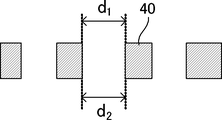
- 4A is a diagram schematically showing a cut surface of a crystalline polymer microporous membrane having a symmetrical hole before functionalization treatment (before hydrophilization treatment and addition reaction treatment) in Comparative Example 2.
- FIG. FIG. 4B is a diagram schematically showing a cut surface of a crystalline polymer microporous membrane having a symmetrical hole after functionalization treatment (after hydrophilization treatment and addition reaction treatment) in Comparative Example 2.
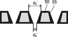
- FIG. 5A is a diagram schematically showing a cut surface of a crystalline polymer microporous membrane having asymmetric pores before functionalization treatment (after hydrophilization treatment and addition reaction treatment) in Example 1.
- FIG. 5B is a diagram schematically showing a cut surface of a crystalline polymer microporous membrane having asymmetric pores after functionalization treatment (after hydrophilization treatment and addition reaction treatment) in Example 1.
- FIG. 5A is a diagram schematically showing a cut surface of a crystalline polymer microporous membrane having asymmetric pores before functionalization treatment (after hydrophilization treatment and addition reaction treatment) in Example 1.
- FIG. 5B is a diagram schematically showing a cut surface of a crystalline polymer microporous membrane having asymmetric pores after functionalization treatment (after hydrophilization treatment and addition reaction treatment) in Example 1.
- the crystalline polymer microporous membrane of the present invention is a crystalline polymer microporous membrane having an asymmetric pore structure, wherein at least a part of the exposed surface of the crystalline polymer microporous membrane contains a radical polymerizable monomer.
- a functional polymer containing at least one of an ion exchange group and a chelate group is subjected to an addition reaction with at least a part of the radical polymer.
- the method for producing a crystalline polymer microporous membrane of the present invention includes a hydrophilization treatment step and an addition reaction treatment step, and includes an asymmetric heating step, a stretching step, a crystalline polymer film production step, and, if necessary, other methods. Comprising the steps.
- the crystalline polymer microporous membrane and the method for producing the crystalline polymer microporous membrane of the present invention will be described in detail.
- the crystalline polymer microporous membrane of the present invention is a crystalline polymer microporous membrane having an asymmetric pore structure, and a composition containing a radical polymerizable monomer as will be described later.
- the product is coated with a radical polymer obtained by polymerizing the product, and a functional compound containing at least one of an ion exchange group and a chelate group is added to at least a part of the radical polymer.
- the crystalline polymer microporous membrane is preferably obtained by heating one surface of a film made of a crystalline polymer and stretching a semi-fired film having a temperature gradient in the thickness direction of the film. .
- the surface having the larger average pore diameter is defined as the first surface, and is located on the opposite side of the first surface.
- the second surface is preferably a heating surface.
- the hole is a continuous hole (both ends are open) from the first surface to the second surface.
- the first surface having the larger average pore diameter is referred to as “non-heated surface”
- the second surface having the smaller average pore diameter is referred to as “heating surface”. This is merely a name given for convenience in order to make the description of the present invention easier to understand. Therefore, any surface of the unsintered crystalline polymer film may be heated to become a “heating surface” after semi-sintering.
- the “crystalline polymer” is not particularly limited as long as it is a polymer in which a crystalline region in which long chain molecules are regularly arranged in a molecular structure and an amorphous region that is not regularly arranged are mixed. Can be appropriately selected according to the purpose. Such polymers exhibit crystallinity by physical treatment. For example, when a polyethylene film is stretched by an external force, a phenomenon in which a transparent film becomes cloudy at first is recognized. This is because the crystallinity is expressed by aligning the molecular arrangement in the polymer in one direction by an external force.
- polyalkylene, polyester, polyamide, polyether, a liquid crystalline polymer etc. are mentioned.
- polyalkylene for example, polyethylene and polypropylene
- fluorine-based polyalkylene in which the hydrogen atoms of the alkylene group in the polyalkylene are partially or entirely substituted with fluorine atoms.
- PTFE polytetrafluoroethylene
- the density of the polyethylene varies depending on the degree of branching, the degree of branching is high, and the degree of crystallization is low density polyethylene (LDPE), the degree of branching is low and the degree of crystallization is high density polyethylene (HDPE). Any of these can be used.
- LDPE low density polyethylene
- HDPE high density polyethylene
- HDPE high density polyethylene
- the glass transition temperature of the crystalline polymer is preferably 40 ° C. to 400 ° C., more preferably 50 ° C. to 350 ° C. Further, the mass average molecular weight of the crystalline polymer is preferably 1,000 to 100,000,000. The number average molecular weight of the crystalline polymer is preferably 500 to 50,000,000, more preferably 1,000 to 10,000,000.
- the average pore diameter in the first surface is larger than the average pore diameter in the second surface, and the average pore diameter from the first surface toward the second surface is It has a plurality of continuously changing holes, that is, the average hole diameter of the non-heated surface (first surface) is larger than the average hole diameter of the heated surface (second surface).
- the crystalline polymer microporous membrane has a thickness of “10”, an average pore diameter in the thickness portion “1” in the depth direction from the surface is P1, and an average pore diameter in the thickness portion of “9” is P2.
- P1 / P2 is preferably 2 to 10,000, more preferably 3 to 100.
- the ratio of the average pore diameter between the non-heated surface and the heated surface is preferably 5 to 30 times, more preferably 10 to 25 times. A ratio of 15 to 20 times is particularly preferable.
- the average pore diameter of the pores on the non-heated surface (first surface) of the crystalline polymer microporous membrane is not particularly limited and may be appropriately selected depending on the intended purpose, but is 0.1 ⁇ m to 500 ⁇ m. Preferably, 0.25 ⁇ m to 250 ⁇ m is more preferable, and 0.50 ⁇ m to 100 ⁇ m is particularly preferable.
- the average pore diameter of the pores on the heating surface (second surface) of the crystalline polymer microporous membrane is not particularly limited and may be appropriately selected depending on the intended purpose, but is 0.01 ⁇ m to 5.0 ⁇ m. Is preferable, 0.025 ⁇ m to 2.5 ⁇ m is more preferable, and 0.05 ⁇ m to 1.0 ⁇ m is particularly preferable.
- the flow rate may decrease, and if it exceeds 5.0 ⁇ m, fine particles may not be efficiently captured.
- it is advantageous in terms of flow rate and fine particle capturing ability.
- the average pore diameter is, for example, a photograph of the film surface (SEM photograph, magnification 1,000 ⁇ to 1,000 times) with a scanning electron microscope (Hitachi S-4000 type, vapor deposition is Hitachi E1030 type, both manufactured by Hitachi, Ltd.) 5,000 times) and the obtained photograph is converted into an image processing apparatus (main body name: Nippon Avionics Co., Ltd., TV image processor TVIP-4100II, control software name: Ratok System Engineering Co., Ltd., TV image processor image command 4198
- the average pore diameter can be obtained by obtaining an image consisting only of crystalline polymer fibers, measuring a predetermined number of pore diameters in the image, and calculating the image.
- the crystalline polymer microporous membrane of the present invention has an average pore diameter that continuously changes from the non-heated surface (first surface) to the heated surface (second surface).
- first embodiment both the embodiment having the single layer structure (second embodiment) are included. By further adding these additional features, the filter life can be effectively improved.
- the average pore diameter continuously changes from the non-heated surface to the heated surface means that the horizontal axis indicates the distance t in the thickness direction from the non-heated surface (the depth from the surface). This means that the graph is drawn with one continuous line when the average pore diameter D is taken on the vertical axis.
- a region and a region with a zero slope may be mixed, or a region with a negative slope and a positive region (dD / dt> 0) may be mixed.
- the non-heated surface of the film is included in the region where the inclination is negative.
- the slope may be always constant or different.
- the crystalline polymer microporous membrane of the present invention consists only of a negative slope region (dD / dt ⁇ 0)
- the dD on the heated surface of the membrane is higher than the dD / dt on the non-heated surface of the membrane
- a mode in which / dt is large can be taken.
- the “single layer structure” in the second aspect excludes a multilayer structure formed by laminating or laminating two or more layers. That is, the “single layer structure” in the second aspect means a structure having no boundary between layers existing in a multilayer structure. In the second aspect, it is preferable that a surface having an average pore size smaller than the average pore size of the non-heated surface and larger than the average pore size of the heated surface is present in the film.
- the crystalline polymer microporous membrane of the present invention preferably has both the features of the first embodiment and the features of the second embodiment. That is, the average pore diameter of the non-heated surface of the crystalline polymer microporous membrane is larger than the average pore diameter of the heated surface, the average pore diameter continuously changes from the non-heated surface to the heated surface, and a single layer What is a structure is preferable. With such a crystalline polymer microporous membrane, fine particles can be captured more efficiently when filtration is performed from the non-heated surface side, the filtration life can be greatly improved, and it is easy and inexpensive. Can also be manufactured. *
- the film thickness of the crystalline polymer microporous film is preferably 1 ⁇ m to 300 ⁇ m, more preferably 5 ⁇ m to 100 ⁇ m, and particularly preferably 10 ⁇ m to 80 ⁇ m.
- the exposed surface of the crystalline polymer microporous membrane is coated with a radical polymer obtained by polymerizing a composition containing a radical polymerizable monomer (hydrophilization treatment), and the radical polymer A functional compound containing at least one of an ion exchange group and a chelate group is added to at least a part of (addition reaction treatment).
- the exposed surface includes the periphery of the hole and the inside of the hole.
- the composition containing the radical polymerizable monomer comprises at least one radical polymerizable monomer selected from acrylate, methacrylate, acrylamide, acrylic acid and derivatives thereof, and, if necessary, other radical polymerization.
- Other components such as a polymerizable monomer, a solvent, a radical polymerization initiator, a photosensitizer, and an antioxidant.
- the radical polymerizable monomer is not particularly limited as long as it is at least one selected from acrylate, methacrylate, acrylamide, acrylic acid and derivatives thereof, and can be appropriately selected according to the purpose.
- Alkyl (meth) acrylates such as hydroxy-2-propyl acrylate, 2-hydroxy-1-propyl acrylate, hydroxypropyl methacrylate, 2,3-dihydroxypropyl acrylate, hydroxyethyl acrylate, hydroxyethyl methacrylate, hydroxyethyl methacrylate; 4- Glycidyl (meth) acrylates such as hydroxybutyl acrylate glycidyl ether and glycidyl acrylate; aminoethyl methacrylate, dimethylaminoethyl methacrylate Primary amine (meth) acrylates such as diethylaminoethyl methacrylate; urethane (meth) acrylates; acrylamides such as acrylamide, methacrylamide, ethacrylamide, and N, N-dimethylacrylamide; acrylic acids such as acrylic acid and methacrylic acid; Examples include (meth) acrylic acid chlorides such as acrylic acid chloride
- the radical polymerizable monomer preferably contains at least one of a carboxyl group, an amino group, a hydroxyl group, an epoxy group, an acrylamide group, an isocyanate group, and an acid chloride group.
- examples of the radical polymerizable monomer containing a carboxyl group include acrylic acid, methacrylic acid, and carboxyethyl acrylate.
- examples of the radical polymerizable monomer containing an amino group include dimethylaminoethyl methacrylate and diethylaminoethyl methacrylate.
- Examples of the radical polymerizable monomer containing a hydroxyl group include 4-hydroxybutyl acrylate and hydroxyethyl methacrylate.
- Examples of the radical polymerizable monomer containing an epoxy group include 4-hydroxybutyl acrylate glycidyl ether and glycidyl acrylate.
- Examples of the radical polymerizable monomer containing an acrylamide group include acrylamide and N, N-dimethylacrylamide.
- Examples of the radical polymerizable monomer containing an isocyanate group include urethane (meth) acrylates.
- Examples of the radical polymerizable monomer containing an acid chloride group include acrylic acid chloride.
- Examples of the commercially available products include Desmodur HL (Bayer AG, manufactured by Leverkusen), Roskydal UA VP LS 2265 (Bayer AG, manufactured by Leverkusen), and the like.
- the content of the radical polymerizable monomer in the composition is not particularly limited and may be appropriately selected depending on the intended purpose, but is preferably 0.1% by mass to 30% by mass, and more preferably 0.2% by mass to 25% by mass is more preferable, and 0.3% by mass to 20% by mass is particularly preferable. If the content is less than 0.1% by mass, the entire microporous membrane of the crystalline polymer may not be hydrophilized. If the content exceeds 30% by mass, the crystalline polymer micropores There is a risk that the permeate flow rate may be reduced by closing the pores of the conductive membrane.
- Radical polymerization initiator both a photo radical polymerization initiator and a thermal radical polymerization initiator can be suitably used.
- Irgacure (Irgacure) series for example, Irgacure 651, Irgacure 754, commercially available from BASF Japan Ltd.,
- IRGACURE 184 for example, Irgacure 2959, IRGACURE 907, IRGACURE 369, IRGACURE 379, IRGACURE 819, etc.
- DAROCURE series for example, DAROCURE TPO, DAROCURE 1173 etc.
- Quantacure PDO for example, Sarter (commercial) Ezacure series (for example, Ezacure TZM, Ezacure TZT, etc.) and the like.
- the thermal radical polymerization initiator is not particularly limited and may be appropriately selected depending on the intended purpose.
- the addition amount of the radical polymerization initiator is not particularly limited, but is preferably 0.1 to 20 parts by weight, preferably 0.5 to 15 parts by weight with respect to 100 parts by weight of the radical polymerizable monomer. Is more preferable, and 1.0 to 10 parts by mass is particularly preferable. When the addition amount is less than 0.1 parts by mass, the polymerization reaction may be slow, and when it exceeds 20 parts by mass, the film strength may be brittle.
- the solvent is not particularly limited and may be appropriately selected depending on the intended purpose. Examples thereof include water; alcohols such as methanol, ethanol, isopropanol and ethylene glycol; ketones such as acetone and methyl ethyl ketone (MEK); , Ethers such as dioxane and propylene glycol monomethyl ether acetate; dimethylformamide, dimethyl sulfoxide and the like.
- a photosensitizer can be used in combination with the composition as necessary. By using the photosensitizer, the reactivity is improved, and the mechanical strength and adhesive strength of the cured product can be improved.
- the photosensitizer is not particularly limited and may be appropriately selected depending on the intended purpose. Examples thereof include carbonyl compounds, organic sulfur compounds, persulfides, redox compounds, azo and diazo compounds, halogen compounds, and photoreduction.
- benzoin derivatives such as benzoin methyl ether, benzoin isopropyl ether, ⁇ , ⁇ -dimethoxy- ⁇ -phenylacetophenone; benzophenone, 2,4-dichlorobenzophenone, methyl o-benzoylbenzoate
- Benzophenone derivatives such as 4,4′-bis (diethylamino) benzophenone; thioxanthone derivatives such as 2-chlorothioxanthone and 2-isopropylthioxanthone; anthraquinone derivatives such as 2-chloroanthraquinone and 2-methylanthraquinone;
- acridone derivatives such as lidone and N-butylacridone; ⁇ , ⁇ -diethoxyacetophenone, benzyl, fluorenone, xanthone, and uranyl compounds.
- photosensitizers include Anthracure (registered trademark) UVS-1331 (manufactured by Kawasaki Kasei Kogyo Co., Ltd.) and Kayacure DETX-S (manufactured by Nippon Kayaku Co., Ltd.).
- the said composition can contain other additives, such as antioxidant, unless the effect of this invention is impaired.
- antioxidants include dibutylhydroxytoluene (BHT); Irganox 1010, Irganox 1035FF, Irganox 565 (all manufactured by BASF Japan Ltd.), and the like.
- the crystalline polymer microporous membrane of the present invention at least a part of the exposed surface of the crystalline polymer microporous membrane is coated with a radical polymer obtained by polymerizing a composition containing a radical polymerizable monomer.
- the membrane before coating and the membrane after coating are each made fine, and the crystalline polymer microporous membrane is extracted with a solvent such as methanol, water, DMF, etc., and the components of the extract are NMR, IR, etc. It can be confirmed by measuring and analyzing using
- the membrane is finely chopped and covered with KBr, and measurement and analysis are performed by IR, and supercritical methanol is used.
- the components can be confirmed by measuring and analyzing the components with MASS, NMR, IR, etc. while decomposing the polymer.
- the functional compound described later is added to the radical polymer, and the measurement and analysis are performed by IR while finely chopping the whole film and covered with KBr, and using supercritical methanol, While decomposing the polymer, its components can be confirmed by measurement and analysis by MASS, NMR, IR, and the like.
- the crystalline polymer microporous membrane of the present invention at least a part of the exposed surface of the crystalline polymer microporous membrane is coated with a radical polymer obtained by polymerizing a composition containing a radical polymerizable monomer. Therefore, in addition to the exposed surfaces (first surface and second surface) of the crystalline polymer microporous membrane, the periphery of the hole portion and the inside of the hole portion are uniformly coated, and thus hydrophilic. , High filtration life and excellent permeate flow rate. On the other hand, if at least a part of the exposed surface of the crystalline polymer microporous membrane is coated with a prepolymerized radical polymer, the exposed surface is covered, particularly around the pores and inside the pores.
- the distribution and degree of the radical polymer coating can be identified, for example, by examining the element distribution on the exposed surface by elemental analysis by energy dispersive X-ray scanning electron microscope spectroscopy (EDX-SEM). .
- the crystalline polymer microporous membrane of the present invention at least a part of the exposed surface of the crystalline polymer microporous membrane is coated with a radical polymer obtained by polymerizing a composition containing a radical polymerizable monomer. Therefore, hydrophilicity can be imparted, and a remarkable asymmetric structure can be formed in the asymmetric membrane, thereby further improving the filtration life. This is because the radical polymer is thicker than the coarse filtration portion on the first surface (non-heating surface) side as it goes to the dense portion on the second surface (heating surface) side of the crystalline polymer microporous membrane.
- the exposed surface of the crystalline polymer microporous membrane is coated with a radical polymer obtained by polymerizing the composition containing the radical polymerizable monomer (after hydrophilization treatment), and then the crystalline polymer microparticles are coated.
- the ratio (d 3 ′ / d 4 ′) between the average pore diameter d 3 ′ on the first surface of the porous membrane and the average pore diameter d 4 ′ on the second surface is expressed by the following equation: (d 3 ′ / d 4 ′) / (d 3 / d 4 )> 1 is preferably satisfied, (d 3 ′ / d 4 ′) / (d 3 / d 4 )> 1.005 is more preferable, and (d 3 ′ / D 4 ′) / (d 3 / d 4 )> 1.01 is particularly preferable.
- the lifetime may be extremely low
- the coverage of the radical polymer is not particularly limited as long as at least a part of the exposed surface of the crystalline polymer microporous membrane is coated, and depends on the surface area of the crystalline polymer microporous membrane and the like. For example, it can be appropriately adjusted based on the porosity described in JP-A-8-283447. That is, the surface area has a correlation with the porosity of the crystalline polymer microporous membrane, and the coverage of the radical polymer can be optimized in relation to the porosity. It can be calculated using the following formula (1) and the following formula (2).
- the porosity is not particularly limited and may be appropriately selected depending on the intended purpose, but is preferably 60% or more, more preferably 60% to 95%.
- the porosity When the porosity is less than 60%, the hydrophilicity becomes low, and a desired permeation flow rate may not be obtained in the crystalline polymer microporous membrane.
- the porosity exceeds 95%, the crystalline polymer The strength of the microporous membrane may decrease.
- the lower the porosity of the crystalline polymer microporous membrane the lower the coverage of the radical polymer, and conversely, the higher the porosity, the higher the coverage, but the range is the following formula (1) and It should just be in the range prescribed
- the coverage is less than the range defined by the following formula (1) and the following formula (2), a crystalline polymer microporous membrane having high hydrophilicity and a long filtration life may not be obtained.
- the functional compound is not particularly limited as long as it contains at least one of an ion exchange group and a chelate group, and can be appropriately selected according to the purpose.
- the ion exchange group is a functional group that captures metal ions and the like by ionic bonds.
- the ion exchange group is not particularly limited as long as it is a functional group that ionically bonds to a metal ion or the like, and can be appropriately selected according to the purpose.
- a sulfonic acid group a phosphoric acid group, a carboxyl group, etc.
- Anion exchange groups such as cation exchange groups, primary amino groups, secondary amino groups, tertiary amino groups, quaternary amino groups, and quaternary ammonium bases can be mentioned.
- the chelate group is a functional group that captures a metal ion or the like by a chelate (coordination) bond.
- the chelate group is not particularly limited as long as it is a functional group capable of chelate (coordination) bonding with a metal ion, and can be appropriately selected according to the purpose.
- NTA nitrilotriacetic acid derivative
- iminodiacetic acid Group iminodiacetic acid Group
- iminodiethanol group aminopolycarboxylic acid, aminopolyphosphonic acid, porphyrin skeleton, phthalocyanine skeleton, cyclic ether, cyclic amine, phenol and lysine derivatives, phenanthrolin group, terpyridine group, bipyridine group, triethylenetetraamine group
- Multidentate ligands such as diethylenetriamine group, tris (carboxymethyl) ethylenediamine group, diethylenetriaminepentaacetic acid group, polypyrazolylboric acid group, 1,4,7-triazocyclononane group, dimethylglyoxime group, diphenylglyoxime group Etc.
- a reactive group with the said radical polymer there is no restriction
- Specific examples of the functional compound having a reactive group include an amino group as a reactive group, pentaethylenehexamine, aminoethanesulfonic acid, phosphorylethanolamine, etc .; a hydroxyethylenediamine group having a reactive group as a hydroxyl group.
- the functional compound is present in the side chain of the radical polymer because the radical wall surface of the crystalline polymer microporous membrane (film made of a crystalline polymer) is coated with a radical polymerizable monomer and fixed by polymerization. By addition reaction to the reactive group, it is fixed to the crystalline polymer microporous membrane in a non-covalent bond state. Further, the fact that the functional compound is fixed to the crystalline polymer microporous membrane can be confirmed by, for example, a back titration method described in JP-A-2005-131482.
- a flow rate can be increased by fixing the functional compound to a membrane.
- the flow rate is generally determined by the hole diameter (D), the pressure loss ( ⁇ P), the number of holes (n), the film thickness (L), and the liquid viscosity ( ⁇ ) as shown in the following formula.
- the method for producing a crystalline polymer microporous membrane according to the present invention includes at least a hydrophilization treatment step and an addition reaction treatment step, and includes a crystalline polymer film preparation step, an asymmetric heating step, a stretching step, and, if necessary, other processes. Comprising the steps.
- the hydrophilic treatment and the addition reaction treatment are collectively referred to as functionalization treatment.
- ⁇ Crystalline polymer film production process> There is no restriction
- the crystalline polymer mentioned above can be used preferably.
- polyethylene or a crystalline polymer in which a hydrogen atom is substituted with a fluorine atom is preferable, and for example, polytetrafluoroethylene (PTFE) is more preferable.
- PTFE polytetrafluoroethylene
- polytetrafluoroethylene produced by an emulsion polymerization method can be usually used, preferably a fine powder obtained by coagulating an aqueous dispersion obtained by emulsion polymerization.
- Polytetrafluoroethylene can be used.
- the number average molecular weight of the crystalline polymer used as a raw material is preferably 500 to 50,000,000, and more preferably 1,000 to 10,000,000.
- the number average molecular weight of polytetrafluoroethylene used as a raw material is preferably 2.5 million to 10 million, and more preferably 3 million to 8 million.
- a film by preparing a mixture obtained by mixing the polytetrafluoroethylene raw material with an extrusion aid, and extruding and rolling the mixture.
- an extrusion aid a liquid lubricant is preferably used, and specific examples thereof include solvent naphtha and white oil.
- a hydrocarbon oil such as “Isopar” manufactured by Esso Oil Co., Ltd. sold in the market can be used.
- the addition amount of the extrusion aid is preferably 20 to 30 parts by mass with respect to 100 parts by mass of the crystalline polymer.
- Paste extrusion is usually preferably carried out at 50 ° C to 80 ° C.
- the extrudate is then rolled into a film. Rolling can be performed, for example, by calendaring with a calendar roll at a speed of 50 m / min.
- the rolling temperature can usually be set to 50 ° C to 70 ° C.
- it is preferable to remove the extrusion aid by heating the film to obtain a crystalline polymer unfired film.
- the heating temperature at this time can be appropriately determined according to the type of crystalline polymer to be used, but is preferably 40 ° C to 400 ° C, more preferably 60 ° C to 350 ° C.
- polytetrafluoroethylene it is preferably 150 ° C. to 280 ° C., more preferably 200 ° C. to 255 ° C.
- the heating can be performed by a method such as passing the film through a hot air drying furnace.
- the thickness of the unsintered crystalline polymer film thus produced can be appropriately adjusted according to the thickness of the crystalline polymer microporous film to be finally produced, and is stretched in a later step. In such a case, it is preferable to adjust the thickness in consideration of stretching.
- the items described in “Polyfluorocarbon Handbook” published by Daikin Industries, Ltd., revised in 1983) can be appropriately employed.
- the asymmetric heating step is a step of heating one surface of a film made of a crystalline polymer to form a semi-baked film in which a temperature gradient is formed in the thickness direction of the film.
- the semi-firing means that the crystalline polymer is heat-treated at a temperature not lower than the melting point of the fired body and not higher than the melting point of the unfired body + 15 ° C.
- an unsintered body of a crystalline polymer means one that has not been subjected to a heat treatment for firing.
- the melting point of the crystalline polymer means the temperature of the endothermic curve peak that appears when the unsintered crystalline polymer is measured with a differential scanning calorimeter.
- the melting point of the fired body and the melting point of the unfired body vary depending on the kind of crystalline polymer, average molecular weight, etc., but are preferably 50 ° C. to 450 ° C., more preferably 80 ° C. to 400 ° C.
- a temperature can be considered as follows.
- the crystalline polymer is polytetrafluoroethylene
- the sintered body has a melting point of about 324 ° C.
- the green body has a melting point of about 345 ° C. Therefore, in the case of a polytetrafluoroethylene film, the temperature is preferably 327 ° C. to 360 ° C., more preferably 335 ° C. to 350 ° C., for example, 345 ° C.
- the semi-fired body is in a state where a melting point of about 324 ° C. and a melting point of about 345 ° C. are mixed.
- the semi-baking is performed by heating one surface (heating surface) of a film made of a crystalline polymer.
- the heating temperature can be controlled asymmetrically in the thickness direction, and the crystalline polymer microporous membrane of the present invention can be easily produced.
- the temperature gradient in the thickness direction of the film made of the crystalline polymer is preferably 30 ° C. or more, and more preferably 50 ° C. or more.
- the heating method various methods such as a method of blowing hot air, a method of contacting with a heating medium, a method of contacting with a heated material, a method of irradiating infrared rays, and heating by electromagnetic waves such as microwaves can be used.
- a heating roll as the heated product. If it is a heating roll, the semi-firing can be carried out continuously in a flow operation industrially, and temperature control and maintenance of the apparatus are easy.
- the temperature of the heating roll can be set to the temperature at which the semi-fired body is formed.
- the time for which the film is brought into contact with the heating roll is the time necessary for the target half-baking to sufficiently proceed, preferably 30 seconds to 120 seconds, more preferably 45 seconds to 90 seconds, and more preferably 60 seconds to 80 seconds. Is more preferable.
- the infrared ray means an electromagnetic wave having a wavelength of 0.74 ⁇ m to 1,000 ⁇ m, of which a wavelength range of 0.74 ⁇ m to 3 ⁇ m is a near infrared ray, and a wavelength range of 3 ⁇ m to 1,000 ⁇ m is a far infrared ray. Infrared.
- far infrared rays advantageous for heating the surface layer are preferably used.
- the type of the apparatus for performing infrared irradiation is not particularly limited as long as it can irradiate infrared light having a target wavelength, and can be appropriately selected according to the purpose.
- far-infrared rays can be a heating element such as ceramic, quartz, or metal oxide surface.
- a semi-baking can be performed continuously by a flow operation industrially, and also temperature control and apparatus maintenance are easy.
- the film surface temperature by the infrared irradiation can be controlled by the output of the infrared irradiation apparatus, the distance between the infrared irradiation apparatus and the film surface, the irradiation time (conveying speed), and the ambient temperature, and is set to the temperature at which the above-mentioned semi-baked body is formed
- it is preferably 327 ° C. to 380 ° C., more preferably 335 ° C. to 360 ° C.
- the surface temperature is less than 327 ° C., the crystal state does not change, and the pore diameter may not be controlled.
- the irradiation time of the infrared rays is not particularly limited, and is a time necessary for the intended half-baking to sufficiently proceed, preferably 30 seconds to 120 seconds, more preferably 45 seconds to 90 seconds, and more preferably 60 seconds to 80 seconds is more preferable.
- the heating in the asymmetric heating step may be performed continuously, or may be performed intermittently by dividing into several times.
- the heating surface of the film is continuously heated, it is preferable to cool the non-heating surface simultaneously with the heating of the heating surface in order to maintain a temperature gradient between the heating surface and the non-heating surface of the film.
- the method for cooling the non-heated surface is not particularly limited and may be appropriately selected depending on the purpose. For example, a method of blowing cold air, a method of contacting with a refrigerant, a method of contacting with a cooled material, or by cooling. Various methods such as cooling can be used, and it is preferably performed by bringing a cooling material into contact with the non-heated surface of the film.
- a cooling roll As the cooling object, it is particularly preferable to select a cooling roll as the cooling object. If it is a cooling roll, like the heating of a heating surface, it can carry out an industrial semi-baking continuously by a flow operation
- the temperature of the cooling roll can be set so as to cause a difference from the temperature at which the semi-fired body is formed.
- the time for which the film is brought into contact with the cooling roll is the time required for the intended semi-baking to sufficiently proceed, and is usually 30 seconds to 120 seconds, assuming that the film is performed simultaneously with the heating step. Preferably, it is 45 seconds to 90 seconds, and more preferably 60 seconds to 80 seconds.
- the surface material of the heating roll and cooling roll can be stainless steel, which is generally excellent in durability, and particularly SUS316.
- the non-heated surface of the film is preferably brought into contact with the heating and cooling roll, but a roller set at a temperature lower than that of the heating and cooling roll may be brought into contact with the heating surface of the film. Absent. For example, a roller maintained at room temperature may be pressed from the film heating surface to fit the film to the heating roll. Moreover, you may make the heating surface of a film contact a guide roll before or after making it contact with a heating roll. Moreover, also when performing the said asymmetrical heating process intermittently, it is preferable to suppress the temperature rise of a non-heating surface by heating the heating surface of a film intermittently and cooling a non-heating surface.
- the stretching step is a step of stretching the semi-baked film.
- the stretching is preferably performed in both the longitudinal direction and the width direction of the semi-baked film.
- the longitudinal direction and the width direction may be sequentially stretched or biaxially stretched at the same time.
- the stretching ratio in the longitudinal direction is preferably 4 to 100 times, more preferably 8 to 90 times, and still more preferably 10 to 80 times.
- the stretching temperature in the longitudinal direction is preferably 100 ° C. to 300 ° C., more preferably 200 ° C. to 290 ° C., and particularly preferably 250 ° C. to 280 ° C.
- the draw ratio in the width direction is preferably 10 to 100 times, more preferably 12 to 90 times, still more preferably 15 to 70 times, and particularly preferably 20 to 40 times.
- the stretching temperature in the width direction is preferably 100 ° C to 300 ° C, more preferably 200 ° C to 290 ° C, and particularly preferably 250 ° C to 280 ° C.
- the area stretch ratio is preferably 50 to 300 times, more preferably 75 to 280 times, and still more preferably 100 to 260 times. When stretching, the film may be preheated to a temperature below the stretching temperature.
- heat setting can be performed as necessary after the stretching.
- the heat setting temperature is usually preferably higher than the stretching temperature and lower than the melting point of the crystalline polymer fired body.
- the hydrophilization treatment step is a step of applying a composition containing at least a radical polymerizable monomer to the exposed surface of the film and polymerizing the radical polymerizable monomer.
- the composition containing the radically polymerizable monomer at least in the said hydrophilization treatment process there is no restriction
- the radically polymerizable monomer contained in the composition is polymerized by subjecting the film after application (immersion or coating) to ultraviolet irradiation or heat treatment (annealing).
- the composition containing at least a radically polymerizable monomer contains a photoradical polymerization initiator
- the radically polymerizable monomer is radically polymerized by ultraviolet irradiation treatment to coat the polymer on the exposed surface of the film.
- the illuminance condition for the ultraviolet irradiation treatment is preferably 1.0 ⁇ 10 2 mJ / cm 2 to 1.0 ⁇ 10 5 mJ / cm 2 , and preferably 5.0 ⁇ 10 2 mJ / cm 2 to 5.0 ⁇ 10. 4 mJ / cm 2 is more preferable.
- the radically polymerizable monomer is radically polymerized by heat treatment to coat the polymer on the exposed surface of the film.
- the temperature in the heat treatment is preferably 50 ° C. to 200 ° C., more preferably 60 ° C. to 180 ° C., and particularly preferably 70 ° C. to 160 ° C.
- the time for the heat treatment is preferably 1 minute to 120 minutes, more preferably 1 minute to 100 minutes, and particularly preferably 1 minute to 80 minutes. If the temperature of the annealing treatment is less than 50 ° C.
- the hydrophilic treatment may not be promoted, the polymerization reaction may not proceed, water resistance, hydrophilicity, etc. may be lost.
- the temperature exceeds 200 ° C. or the time exceeds 80 minutes, the radical polymerizable monomer may be decomposed.
- the addition reaction step is a step of causing an addition reaction of a functional compound containing at least one of an ion exchange group and a chelate group to at least a part of the radical polymer.
- the method for addition reaction of the functional compound to at least a part of the radical polymer is not particularly limited and may be appropriately selected depending on the purpose.
- film (Porous membrane) is impregnated with a mixed solution containing at least a radical polymerizable monomer and a functional compound, and subjected to a heat treatment (thermal annealing) to polymerize and coat the radical polymerizable monomer (hydrophilic treatment);
- a method of simultaneously causing an addition reaction between at least a part of a radical polymer and a functional compound (ii) impregnating a mixed solution containing at least a radical polymerizable monomer and a functional compound with an ultraviolet irradiation treatment; Then, the radical polymerizable monomer is polymerized and coated, followed by heat treatment (thermal annealing), and the radical polymerization (Iii) impregnating a composition containing at least a radical polymerizable monomer with (iii)
- the illuminance condition for the ultraviolet irradiation treatment is preferably 1.0 ⁇ 10 2 mJ / cm 2 to 1.0 ⁇ 10 5 mJ / cm 2 , and preferably 5.0 ⁇ 10 2 mJ / cm 2 to 5.0 ⁇ 10. 4 mJ / cm 2 is more preferable.
- the temperature in the heat treatment is preferably 50 ° C. to 200 ° C., more preferably 50 ° C. to 180 ° C., and particularly preferably 50 ° C. to 160 ° C.
- the time for the heat treatment is preferably 0.5 minutes to 300 minutes, more preferably 0.75 minutes to 200 minutes, and particularly preferably 1 minute to 100 minutes.
- the crystalline polymer microporous membrane of the present invention is not particularly limited and can be used for various applications, but can be suitably used as a filter for filtration described below.
- the filter for filtration of the present invention has the crystalline polymer microporous membrane of the present invention.
- filtration is performed with the non-heated surface (surface having a large average pore diameter) as the inlet side. That is, the surface side having a large pore size is used as the filter surface of the filter. In this way, fine particles can be efficiently captured by performing filtration with the surface having a large average pore diameter (non-heated surface) as the inlet side.
- the crystalline polymer microporous membrane of the present invention has a large specific surface area, the fine particles introduced from the surface are removed by adsorption or adhesion before reaching the minimum pore diameter portion. Therefore, clogging is unlikely to occur and high filtration efficiency can be maintained over a long period of time.
- the filtration filter of the present invention can be filtered at least 5 ml / cm 2 ⁇ min or more when filtration is performed at a differential pressure of 0.1 kg / cm 2 .
- a pleat type for folding the filtration membrane a spiral type for filtering the filtration membrane, a frame-and-plate type for laminating disc-shaped filtration membranes, a filtration membrane, There is a tube type etc. which make it tubular.
- the pleated type is particularly preferable because the effective surface area used for filtering the filter per cartridge can be increased.
- an element exchange type filter cartridge that replaces only the filter element when replacing a deteriorated filter membrane
- a capsule type filter cartridge that is processed into a filter housing with the filter housing integrated into a disposable type. Any of the filtering filters of the invention can be suitably used.
- FIG. 1 is a development view showing the structure of an element exchange type pleated filter cartridge element.
- the microfiltration membrane 103 is folded in a state of being sandwiched by two membrane supports 102 and 104, and is wound around a core 105 having a large number of liquid collection ports.
- Microfiltration membranes are sealed at both ends of the cylinder by end plates 106a and 106b. The end plate is in contact with the seal portion of the filter housing (not shown) via the gasket 107. The filtered liquid is collected from the core collection port and discharged from the fluid outlet 108.
- FIG. 2 is a developed view showing the entire structure of the microfiltration membrane filter element before being assembled into the housing of the capsule filter cartridge.
- the microfiltration membrane 2 is folded in a sandwiched state by two supports 1 and 3 and is wound around a filter element core 7 having a large number of liquid collection ports.
- the microfiltration membrane is sealed by the upper end plate 4 and the lower end plate 5 at both ends of the cylinder.
- FIG. 3 shows a structure of a capsule-type pleated filter cartridge in which a filter element is integrated in a housing.
- the filter element 10 is incorporated in a housing composed of a housing base 12 and a housing cover 11.
- the lower end plate 5 is sealed by a water collecting pipe (not shown) at the center of the housing base 12 via an O-ring 8.
- the liquid enters the housing from the liquid inlet nozzle 13, passes through the filter medium 9, is collected from the liquid collection port of the filter element core 7, and is discharged from the liquid outlet nozzle 14.
- the housing base 12 and the housing cover 11 are usually heat-sealed in a liquid-tight manner at the welding portion 17.
- An air vent 15 is provided at the upper part of the housing, and a drain 16 is provided at the lower part of the housing.
- FIGS. 2 and 3 show an example in which the lower end plate 5 and the housing base 12 are sealed through the O-ring 8, but the sealing between the lower end plate 5 and the housing base 12 is performed by heat fusion or adhesion. Sometimes it is done with agents. Alternatively, the seal between the housing base 12 and the housing cover 11 may be a method using an adhesive in addition to heat fusion. 1 to 3 show specific examples of the microfiltration filter cartridge, and the present invention is not limited to these drawings.
- the filter for filtration using the crystalline polymer microporous membrane of the present invention has such a characteristic that the filtration function is high and the life is long, so that the filtration device can be compactly assembled.
- a large number of filtration units are used in parallel to cope with the short filtration life.
- the number of filtration units used in parallel is greatly increased. Can be reduced.
- the replacement period of the filter for filtration can be extended significantly, the cost and time required for maintenance can be reduced.
- the filtration filter of the present invention can be used in various situations where filtration is required, and is preferably used for microfiltration of gases, liquids, etc. Used for filtration and sterilization of process water and food water.
- the filter for filtration of the present invention is excellent in ion adsorption capacity, it can be effectively used, for example, in the production of ultrapure water as an ion exchange membrane or ion adsorption membrane.
- Example 1 ⁇ Production of crystalline polymer microporous membrane (1)> -Production of semi-baked film- 100 parts by mass of polytetrafluoroethylene fine powder (Daikin Industries, Ltd., “Polyflon Fine Powder F104U”) having a number average molecular weight of 6.2 million, and hydrocarbon oil (Esso Petroleum Corporation, “Isopar”) as an extrusion aid ) 27 parts by mass was added, and paste extrusion was performed in a round bar shape. This was calendered at a speed of 50 m / min with a calender roll heated to 70 ° C. to produce a polytetrafluoroethylene film. This film was passed through a hot air drying oven at 250 ° C.
- a polytetrafluoroethylene unfired film having an average thickness of 100 ⁇ m, an average width of 150 mm, and a specific gravity of 1.55 was produced.
- One side (heated surface) of the obtained polytetrafluoroethylene unfired film was heated for 1 minute with a roll (surface material: SUS316) heated to 345 ° C. to produce a semi-fired film.
- the obtained semi-baked film was stretched between rolls by 12.5 times in the longitudinal direction at 270 ° C. and once wound on a winding roll. Then, after preheating the film to 305 ° C., both ends were sandwiched between clips and stretched 30 times in the width direction at 270 ° C. Thereafter, heat setting was performed at 380 ° C.
- the area stretch ratio of the obtained crystalline polymer microporous membrane was 260 times in terms of stretched area ratio.
- Example 2 Preparation of crystalline polymer microporous membrane (2)> A functionalized crystalline polymer microporous membrane (2) was produced in the same manner as in Example 1 except that the functionalization treatment in Example 1 was replaced with the following functionalization treatment.
- the crystalline polymer microporous membrane is immersed in a methanol / MEK mixed solution of 5% by mass acrylic acid (manufactured by TCI) and 0.1% by mass Irgacure 907 (manufactured by BASF Japan Ltd.) as a photo radical polymerization initiator.
- the pulled crystalline polymer microporous film was irradiated with UV.
- the crystalline polymer microporous film soaked in a methanol solution of 5.0 mass% pentaethylenehexamine was annealed at 150 ° C. for 10 minutes in the air.
- the crystalline polymer microporous film soaked in a toluene solution of 10% by mass ethylene sulfide (manufactured by Tokyo Chemical Industry Co., Ltd.) was annealed at 100 ° C. for 10 minutes in the atmosphere. Thereafter, the film was immersed in methanol for 30 minutes, washed, and dried to produce a functionalized crystalline polymer microporous membrane (2).
- the reaction compound of the said ethylene sulfide and the said pentaethylenehexamine functions as a functional compound which has a chelate group.
- Example 3 ⁇ Preparation of crystalline polymer microporous membrane (3)>
- N- (2-hydroxyethyl) ethylenediaminetriacetic acid manufactured by Dojindo Laboratories
- 5% by mass of N- (2-hydroxyethyl) ethylenediaminetriacetic acid manufactured by Dojindo Laboratories
- 3-hydroxypropanesulfonic acid manufactured by Tokyo Chemical Industry Co., Ltd.
- a crystalline polymer microporous membrane (3) was prepared.
- Example 1 ⁇ Preparation of crystalline polymer microporous membrane (4)>
- the crystalline polymer micro of Comparative Example 1 comprising the crystalline polymer microporous film, which is an asymmetric membrane of polytetrafluoroethylene, was prepared in the same manner as in Example 1 except that the functionalization treatment was not performed.
- a porous membrane (4) was produced.
- Example 2 ⁇ Preparation of crystalline polymer microporous membrane (5)>
- a polytetrafluoroethylene microporous membrane manufactured by Nippon Gore Co., Ltd .: symmetrical membrane
- Example 2 a crystalline polymer microporous film (5) of Comparative Example 2 was produced.
- Example 3 A crystalline polymer microporous membrane (6) of Comparative Example 3 was produced in the same manner as in Example 1 except that the functionalization treatment in Example 1 was replaced with the following functionalization treatment. That is, instead of coating with a radical polymer obtained by polymerizing a composition containing a radical polymerizable monomer and subjecting at least a part of the radical polymer to an addition reaction with a functional compound, a previously polymerized radical polymer (polymer) And a functional compound was added to at least a part of the radical polymer.
- a crystalline polymer microporous membrane is immersed in a MEK solution of a radical polymer of 5% by mass of 4-hydroxybutyl acrylate glycidyl ether and dried, followed by 5% by mass of N- (2-hydroxyethyl) ethylenediaminetriacetic acid.
- the crystalline polymer microporous membrane soaked in a methanol solution was annealed at 150 ° C. for 10 minutes in the air. This produced a functionalized crystalline polymer microporous membrane (6).
- the cut surface is scanned with a scanning electron microscope (Hitachi S-4000 type, vapor deposition is Hitachi E1030 type, both manufactured by Hitachi, Ltd.) and a photograph of the film surface (SEM photograph, magnification 1,000 to 5,000 times)
- the obtained photograph is taken into an image processing apparatus (main body name: Nippon Avionics Co., Ltd., TV image processor TVIP-4100II, control software name: Ratok System Engineering Co., Ltd., TV image processor image command 4198) and crystallinity is obtained.
- An image consisting only of polymer fibers was obtained.
- 100 pore diameters were measured and processed to obtain an average pore diameter.
- FIG. 4A is a diagram schematically showing a cut surface of a crystalline polymer microporous membrane having a symmetrical hole before functionalization treatment (before hydrophilization treatment and addition reaction treatment) in Comparative Example 2.
- FIG. 4A is a diagram schematically showing a cut surface of a crystalline polymer microporous membrane having a symmetrical hole before functionalization treatment (before hydrophilization treatment and addition reaction treatment) in Comparative Example 2.
- FIG. 4A is a diagram schematically showing a cut surface of a crystalline polymer microporous membrane having a symmetrical hole after functionalization treatment (after hydrophilization treatment and addition reaction treatment) in Comparative Example 2.
- the average pore diameter on the first surface of the crystalline polymer microporous membrane 40 having a symmetrical hole after the functionalization treatment (hydrophilization treatment and addition reaction treatment, coating portion 45) in FIG. 4B is defined as d 1 ′.
- d 1 in the observed SEM images' average pore diameter in the second surface d 2' ratio of (d 1 'and d 2 / d 2') was 1.0. Therefore, (d 1 ′ / d 2 ′) / (d 1 / d 2 ) in Comparative Example 2 was 1.0.
- FIG. 5A is a diagram schematically showing a cut surface of a crystalline polymer microporous membrane having asymmetric pores before functionalization treatment (before hydrophilization treatment and addition reaction treatment) in Example 1.
- the average pore diameter on the first surface of the crystalline polymer microporous membrane 50 having asymmetric pores before functionalization treatment (before hydrophilization treatment and addition reaction treatment) is d 3
- the average on the second surface is when the pore size was d 4
- the ratio of d 3 and d 4 in the observed SEM images was 15.
- FIG. 5B is a diagram schematically showing a cut surface of a crystalline polymer microporous membrane having asymmetric pores after functionalization treatment (after hydrophilization treatment and addition reaction treatment) in Example 1.
- FIG. After hydrophilization and addition reaction treatment, the covering portion 55
- the average pore diameter in the first surface of the crystalline polymer microporous membrane 50 having asymmetric pores of the d 3 ' the 'when a, d 3 in the SEM image observed' an average pore diameter in the second surface d 4 'ratio of (d 3' and d 4 / d 4 ') was 15.9. Therefore, (d 3 ′ / d 4 ′) / (d 3 / d 4 ) in Example 1 was 1.06.
- the ratio (d 3 ′ / d 4 ′) of the crystalline polymer microporous membrane after the functionalization treatment (after hydrophilization treatment and addition reaction treatment) in Example 1 and before the functionalization treatment in Example 1 (hydrophilicity) From the comparison with the ratio (d 3 / d 4 ) in the crystalline polymer microporous membrane before the functionalization treatment and the addition reaction treatment, the first surface was obtained before the functionalization treatment (before the hydrophilic treatment and the addition reaction treatment). It was found that the ratio of the average pore diameter on the (non-heated surface) and the average pore diameter on the second surface (heated surface) can be increased.
- ⁇ filtration test >> A filtration test was conducted on the crystalline polymer microporous membranes of Examples 1 to 3 and Comparative Examples 1 to 3. First, an aqueous solution containing 0.01% by mass of polystyrene latex (average particle size 1.5 ⁇ m) is filtered at a differential pressure of 10 kPa, and the permeation amount until clogging is shown in Table 1.
- ⁇ Flow test was performed on the crystalline polymer microporous membranes of Examples 1 to 3 and Comparative Examples 1 to 3 as follows.
- the flow rate was measured according to JIS K3831 under the following conditions.
- the type of the test method was “Pressurized filtration test method”, and the sample was cut into a circle having a diameter of 13 mm and set in a stainless steel holder for measurement. Ion exchange water was used as the test solution, and the time required to filter 100 mL of the test solution at a pressure of 10 kPa was measured, and the flow rate (L / min ⁇ m 2 ) was calculated.
- the results are shown in Table 1.
- the crystalline polymer microporous film of Comparative Example 1 was not hydrophilic and could not be measured, and Comparative Examples 2 to 3 did not exceed 100 L / min ⁇ m 2 .
- each of the crystalline polymer microporous membranes of Examples 1 to 3 is 100 L / min ⁇ m 2 or more, and the flow rate is greatly improved by using the crystalline polymer microporous membrane of the present invention. I found out. The reason why the filtration life and the flow rate are improved is considered to be that the foam permeability is improved and the clogging by the foam is reduced.
- JP-A-2-187136 was referred to for the crystalline polymer microporous membranes of Examples 1 to 3 and Comparative Examples 1 to 3. Specifically, 1 L of an aqueous solution containing 10 ppm of each metal ion (silver, sodium) was prepared, and 10 mL of the aqueous solution was passed through each crystalline polymer microporous membrane in Examples 1 to 3 and Comparative Examples 1 to 3. The measurement was performed by measuring the concentration of metal ions contained in the aqueous solution after permeation. The results are shown in Table 3.
- Example 4 Filter cartridge- The crystalline polymer microporous membrane prepared in Example 1 is sandwiched between two polypropylene nonwoven fabrics, pleated to a pleat width of 10.5 mm, 138 folds are taken and rolled into a cylindrical shape, and the alignment is made. The eyes were welded with an impulse sealer. Both ends of the cylinder were cut off by 2 mm, and the cut surfaces were heat welded to a polypropylene end plate to finish an element exchange type filter cartridge. Since the built-in crystalline polymer microporous membrane is hydrophilic, the produced filter cartridge of the present invention does not require complicated pre-hydrophilic treatment in the aqueous treatment. Moreover, since crystalline polymer is used, it is excellent in solvent resistance. Further, since the hole portion has an asymmetric structure, it has a long life with a large flow rate and hardly clogged.
- the crystalline polymer microporous membrane of the present invention and a filter for filtration using the same are excellent in heat resistance and chemical resistance, and can be used in various situations where filtration is required. It is suitably used for microfiltration of liquids and the like, and can be widely used for filtration, sterilization, high temperature filtration and the like of washing water for electronics industry, pharmaceutical water, water for pharmaceutical manufacturing processes, food water and the like.
Landscapes
- Chemical & Material Sciences (AREA)
- Chemical Kinetics & Catalysis (AREA)
- Inorganic Chemistry (AREA)
- Engineering & Computer Science (AREA)
- Manufacturing & Machinery (AREA)
- Separation Using Semi-Permeable Membranes (AREA)
- Manufacture Of Porous Articles, And Recovery And Treatment Of Waste Products (AREA)
Abstract
【課題】耐水性、及びイオン吸着能に優れ、親水性が高く、濾過寿命が長く、透過流量に優れた結晶性ポリマー微孔性膜、及び該結晶性ポリマー微孔性膜を効率良く製造することができる結晶性ポリマー微孔性膜の製造方法、並びに該結晶性ポリマー微孔性膜を用いた濾過用フィルタの提供。 【解決手段】非対称孔構造を有する結晶性ポリマー微孔性膜であって、前記結晶性ポリマー性微孔膜の露出表面の少なくとも一部が、ラジカル重合性モノマーを含む組成物を重合させてなるラジカル重合体で被覆され、前記ラジカル重合体の少なくとも一部に、イオン交換基及びキレート基の少なくともいずれかを含む官能性化合物が付加反応してなり、前記ラジカル重合性モノマーが、アクリレート、メタクリレート、アクリルアミド及びこれらの誘導体から選択される少なくとも1種である結晶性ポリマー微孔性膜である。
Description
本発明は、気体、液体等の精密濾過に使用される濾過効率の高い結晶性ポリマー微孔性膜及び結晶性ポリマー微孔性膜の製造方法、並びに該結晶性ポリマー微孔性膜を用いた濾過用フィルタに関する。
微孔性膜は古くから知られており、濾過用フィルタ等に広く利用されている。このような微孔性膜としては、例えばセルロースエステルを原料として製造されるもの(特許文献1等参照)、脂肪族ポリアミドを原料として製造されるもの(特許文献2等参照)、ポリフルオロカーボンを原料として製造されるもの(特許文献3等参照)、ポリプロピレンを原料とするもの(特許文献4等参照)、などが挙げられる。
これらの微孔性膜は、電子工業用洗浄水、半導体製造薬液、医薬用水、医薬製造工程用水、食品水等の濾過、滅菌に用いられ、近年、その用途及び使用量が拡大しており、粒子捕捉の点から信頼性の高い微孔性膜が注目されている。これらの中でも、結晶性ポリマーによる微孔性膜は耐薬品性に優れており、特にポリテトラフルオロエチレン(PTFE)を原料とした微孔性膜は、耐熱性及び耐薬品性に優れているため、その需要の伸びが著しい。
これらの微孔性膜は、電子工業用洗浄水、半導体製造薬液、医薬用水、医薬製造工程用水、食品水等の濾過、滅菌に用いられ、近年、その用途及び使用量が拡大しており、粒子捕捉の点から信頼性の高い微孔性膜が注目されている。これらの中でも、結晶性ポリマーによる微孔性膜は耐薬品性に優れており、特にポリテトラフルオロエチレン(PTFE)を原料とした微孔性膜は、耐熱性及び耐薬品性に優れているため、その需要の伸びが著しい。
一般に、微孔性膜の単位面積当たりの濾過可能量は少ない(即ち濾過寿命が短い)。このため、工業的に使用する際には、膜面積を増すため、多くの濾過ユニットを並列して使用することを余儀無くされており、濾過工程のコストダウンの観点から、濾過寿命を上げることが必要とされている。例えば目詰まり等による流量低下に有効な微孔性膜として、インレット側からアウトレット側に向かって平均孔径が徐々に小さくなる非対称孔膜が提案されている。
例えば、膜の表面の平均孔径が裏面の平均孔径よりも大きくて、かつ表面から裏面に向けて平均孔径が連続的に変化する結晶性ポリマーの微孔性膜が提案されている(特許文献5参照)。この提案によると、平均孔径が大きい面(表面)をインレット側として濾過を行うことにより、効率よく微粒子を捕捉することができ、濾過寿命を改善することができる。
例えば、膜の表面の平均孔径が裏面の平均孔径よりも大きくて、かつ表面から裏面に向けて平均孔径が連続的に変化する結晶性ポリマーの微孔性膜が提案されている(特許文献5参照)。この提案によると、平均孔径が大きい面(表面)をインレット側として濾過を行うことにより、効率よく微粒子を捕捉することができ、濾過寿命を改善することができる。
また、非対称孔を有する結晶性ポリマー微孔性膜の親水化処理方法として、例えば特許文献6では、非対称孔構造の結晶性ポリマーの微孔性膜の露出表面を、過酸化水素又は水溶性溶剤の水溶液の含浸、レーザー照射、化学的エッチングなどで親水化処理することが提案されている。
しかし、非対称孔を有する結晶性ポリマー微孔性膜においては、加熱面、非加熱面、及びその内部を有し、それぞれの部位における結晶性ポリマーの結晶化度が異なることから、前記提案の親水化処理方法では、膜全体に対する一律の親水化ができず、親水化処理を行おうとすると、結晶化度に応じた条件ごとに何回かに分けて親水化処理を行う必要があり、効率が悪いものである。また、作製された親水化処理膜の親水性も十分満足できるものではなかった。更に、紫外線レーザー及びArFレーザーを照射して親水化処理する方法では、紫外線レーザー及びArFレーザーの照射により、膜を傷つけることがあり、膜強度を劣化させてしまうという問題もある。
しかし、非対称孔を有する結晶性ポリマー微孔性膜においては、加熱面、非加熱面、及びその内部を有し、それぞれの部位における結晶性ポリマーの結晶化度が異なることから、前記提案の親水化処理方法では、膜全体に対する一律の親水化ができず、親水化処理を行おうとすると、結晶化度に応じた条件ごとに何回かに分けて親水化処理を行う必要があり、効率が悪いものである。また、作製された親水化処理膜の親水性も十分満足できるものではなかった。更に、紫外線レーザー及びArFレーザーを照射して親水化処理する方法では、紫外線レーザー及びArFレーザーの照射により、膜を傷つけることがあり、膜強度を劣化させてしまうという問題もある。
また、結晶性ポリマー微孔性膜の親水化処理方法として、カチオン重合性モノマーと、カチオン重合開始剤とを含み、該カチオン重合性モノマーを重合させて、多孔質膜の表面の少なくとも一部を変性する方法が提案され、更に随意に、第4級アンモニウム塩等を含有する官能性モノマーを含むことが提案されている(特許文献7参照)。
しかし、この提案には、多孔質膜の濾過流量及び濾過寿命を十分満足できるレベルまで向上させることができないという問題がある。
しかし、この提案には、多孔質膜の濾過流量及び濾過寿命を十分満足できるレベルまで向上させることができないという問題がある。
また、近年、半導体の製造においては、それに使用できる純度が極めて高い超々純水等を得るために、微粒子捕捉と同時にppm未満の濃度で微少に存在する金属イオンをも同時に捕捉できるフィルタの出現が望まれている。金属イオン捕捉能力も有し、酸、アルカリ及び酸化剤といった薬液に対する耐性が強く溶出物の少ない精密ろ過フィルタが特に求められるようになっている。従来このような目的に対して、微孔性膜自身にイオン交換機能乃至イオン吸着機能を持たせる試みが為されてきた。
イオン吸着機能を付与した結晶性ポリマー微孔性膜として、例えば、特許文献8では、膜からの活性化された極性基と反応性である官能基を含有し、特定イオンに対する親和性を有する任意のリガンドを付与した多孔質膜が提案されている。
しかし、この提案では、対称孔構造を有する多孔質膜を用いており、そのような多孔質膜を機能化する場合、濾過流量が大幅に向上する訳ではなく、かつ濾過寿命も向上しないという問題がある。
イオン吸着機能を付与した結晶性ポリマー微孔性膜として、例えば、特許文献8では、膜からの活性化された極性基と反応性である官能基を含有し、特定イオンに対する親和性を有する任意のリガンドを付与した多孔質膜が提案されている。
しかし、この提案では、対称孔構造を有する多孔質膜を用いており、そのような多孔質膜を機能化する場合、濾過流量が大幅に向上する訳ではなく、かつ濾過寿命も向上しないという問題がある。
本発明は、従来における前記諸問題を解決し、以下の目的を達成することを課題とする。即ち、本発明は、耐水性、及びイオン吸着能に優れ、親水性が高く、濾過寿命が長く、透過流量に優れた結晶性ポリマー微孔性膜、及び該結晶性ポリマー微孔性膜を効率良く製造することができる結晶性ポリマー微孔性膜の製造方法、並びに該結晶性ポリマー微孔性膜を用いた濾過用フィルタを提供することを目的とする。
前記課題を解決するための手段としては、以下の通りである。即ち、
<1> 非対称孔構造を有する結晶性ポリマー微孔性膜であって、
前記結晶性ポリマー性微孔膜の露出表面の少なくとも一部が、ラジカル重合性モノマーを含む組成物を重合させてなるラジカル重合体で被覆され、前記ラジカル重合体の少なくとも一部に、イオン交換基及びキレート基の少なくともいずれかを含む官能性化合物が付加反応してなり、前記ラジカル重合性モノマーが、アクリレート、メタクリレート、アクリルアミド、アクリル酸及びこれらの誘導体から選択される少なくとも1種であることを特徴とする結晶性ポリマー微孔性膜である。
<2> ラジカル重合性モノマーが、カルボキシル基、アミノ基、ヒドロキシル基、エポキシ基、アクリルアミド基、イソシアネート基、及び酸クロライド基の少なくともいずれかを有する前記<1>に記載の結晶性ポリマー微孔性膜である。
<3> 官能性化合物が、ラジカル重合体との反応性基を有する化合物である前記<1>から<2>のいずれかに記載の結晶性ポリマー微孔性膜である。
<4> 2つの露出表面のうちの第1の面における平均孔径が、該第1の面の反対側に位置する第2の面における平均孔径よりも大きく、かつ前記第1の面から前記第2の面に向かって平均孔径が連続的に変化する複数の孔部を有する前記<1>から<3>のいずれかに記載の結晶性ポリマー微孔性膜である。
<5> 結晶性ポリマー微孔性膜を構成する結晶性ポリマーを含むフィルムの一の面を加熱して、該フィルムの厚み方向に温度勾配を付与した半焼成フィルムを延伸した膜である前記<4>に記載の結晶性ポリマー微孔性膜である。
<6> 第2の面を加熱面とする前記<4>から<5>のいずれかに記載の結晶性ポリマー微孔性膜である。
<7> 露出表面にラジカル重合性モノマー重合体を被覆する前の、結晶性ポリマー微孔性膜の第1の面における平均孔径d3と、第2の面における平均孔径d4との比(d3/d4)と、
露出表面にフッ素系界面活性剤を被覆した後の、結晶性ポリマー微孔性膜の第1の面における平均孔径をd3’と、第2の面における平均孔径d4’との比(d3’/d4’)とが、次式、(d3’/d4’)/(d3/d4)>1、を満たす前記<1>から<6>のいずれかに記載の結晶性ポリマー微孔性膜である。
<8> 結晶性ポリマーが、ポリテトラフルオロエチレン、ポリフッ化ビニリデン、テトラフルオロエチレン・パーフルオロアルキルビニルエーテル共重合体、テトラフルオロエチレン・ヘキサフルオロプロピレン共重合体、テトラフルオロエチレン・エチレン共重合体、ポリフッ化ビニリデン、ポリクロロトリフルオロエチレン、クロロトリフルオロエチレン・エチレン共重合体、ポリエチレン、ポリプロピレン、ナイロン、ポリアセタール、ポリブチレンテレフタレート、ポリエチレンテレフタレート、シンジオタクチック・ポリスチレン、ポリフェニレンサルファイド、ポリエーテルエーテルケトン、全芳香族ポリアミド、全芳香族ポリエステル、及びポリエーテルニトリルから選択される少なくとも1種である前記<1>から<7>のいずれかに記載の結晶性ポリマー微孔性膜である。
<9> 結晶性ポリマーが、ポリテトラフルオロエチレンである前記<1>から<7>のいずれかに記載の結晶性ポリマー微孔性膜である。
<10> 非対称孔構造を有する結晶性ポリマー微孔性膜の露出表面に、ラジカル重合性モノマーを含む組成物を付与し、該ラジカル重合性モノマーを重合させる親水化処理工程と、
前記ラジカル重合体の一部に、イオン交換基及びキレート基の少なくともいずれかを含む官能性化合物を付加反応させる付加反応処理工程とを含み、
前記ラジカル重合性モノマーが、アクリレート、メタクリレート、アクリルアミド、アクリル酸及びこれらの誘導体から選択される少なくとも1種であることを特徴とする結晶性ポリマー微孔性膜の製造方法である。
<11> 結晶性ポリマーからなるフィルムの一の面を加熱して、該フィルムの厚み方向に温度勾配を形成した半焼成フィルムを形成する非対称加熱工程と、
前記半焼成フィルムを延伸して非対称孔構造を有する結晶性ポリマー微孔性膜を形成する延伸工程と、を更に含む前記<10>に記載の結晶性ポリマー微孔性膜の製造方法である。
<12> ラジカル重合性モノマーが、カルボキシル基、アミノ基、ヒドロキシル基、エポキシ基、アクリルアミド基、イソシアネート基、及び酸クロライド基の少なくともいずれかを含む前記<10>から<11>のいずれかに記載の結晶性ポリマー微孔性膜の製造方法である。
<13> 官能性化合物が、ラジカル重合体との反応性基を有する化合物である前記<10>から<12>のいずれかに記載の結晶性ポリマー微孔性膜の製造方法である。
<14> 前記<1>から<9>のいずれかに記載の結晶性ポリマー微孔性膜を有することを特徴とする濾過用フィルタである。
<1> 非対称孔構造を有する結晶性ポリマー微孔性膜であって、
前記結晶性ポリマー性微孔膜の露出表面の少なくとも一部が、ラジカル重合性モノマーを含む組成物を重合させてなるラジカル重合体で被覆され、前記ラジカル重合体の少なくとも一部に、イオン交換基及びキレート基の少なくともいずれかを含む官能性化合物が付加反応してなり、前記ラジカル重合性モノマーが、アクリレート、メタクリレート、アクリルアミド、アクリル酸及びこれらの誘導体から選択される少なくとも1種であることを特徴とする結晶性ポリマー微孔性膜である。
<2> ラジカル重合性モノマーが、カルボキシル基、アミノ基、ヒドロキシル基、エポキシ基、アクリルアミド基、イソシアネート基、及び酸クロライド基の少なくともいずれかを有する前記<1>に記載の結晶性ポリマー微孔性膜である。
<3> 官能性化合物が、ラジカル重合体との反応性基を有する化合物である前記<1>から<2>のいずれかに記載の結晶性ポリマー微孔性膜である。
<4> 2つの露出表面のうちの第1の面における平均孔径が、該第1の面の反対側に位置する第2の面における平均孔径よりも大きく、かつ前記第1の面から前記第2の面に向かって平均孔径が連続的に変化する複数の孔部を有する前記<1>から<3>のいずれかに記載の結晶性ポリマー微孔性膜である。
<5> 結晶性ポリマー微孔性膜を構成する結晶性ポリマーを含むフィルムの一の面を加熱して、該フィルムの厚み方向に温度勾配を付与した半焼成フィルムを延伸した膜である前記<4>に記載の結晶性ポリマー微孔性膜である。
<6> 第2の面を加熱面とする前記<4>から<5>のいずれかに記載の結晶性ポリマー微孔性膜である。
<7> 露出表面にラジカル重合性モノマー重合体を被覆する前の、結晶性ポリマー微孔性膜の第1の面における平均孔径d3と、第2の面における平均孔径d4との比(d3/d4)と、
露出表面にフッ素系界面活性剤を被覆した後の、結晶性ポリマー微孔性膜の第1の面における平均孔径をd3’と、第2の面における平均孔径d4’との比(d3’/d4’)とが、次式、(d3’/d4’)/(d3/d4)>1、を満たす前記<1>から<6>のいずれかに記載の結晶性ポリマー微孔性膜である。
<8> 結晶性ポリマーが、ポリテトラフルオロエチレン、ポリフッ化ビニリデン、テトラフルオロエチレン・パーフルオロアルキルビニルエーテル共重合体、テトラフルオロエチレン・ヘキサフルオロプロピレン共重合体、テトラフルオロエチレン・エチレン共重合体、ポリフッ化ビニリデン、ポリクロロトリフルオロエチレン、クロロトリフルオロエチレン・エチレン共重合体、ポリエチレン、ポリプロピレン、ナイロン、ポリアセタール、ポリブチレンテレフタレート、ポリエチレンテレフタレート、シンジオタクチック・ポリスチレン、ポリフェニレンサルファイド、ポリエーテルエーテルケトン、全芳香族ポリアミド、全芳香族ポリエステル、及びポリエーテルニトリルから選択される少なくとも1種である前記<1>から<7>のいずれかに記載の結晶性ポリマー微孔性膜である。
<9> 結晶性ポリマーが、ポリテトラフルオロエチレンである前記<1>から<7>のいずれかに記載の結晶性ポリマー微孔性膜である。
<10> 非対称孔構造を有する結晶性ポリマー微孔性膜の露出表面に、ラジカル重合性モノマーを含む組成物を付与し、該ラジカル重合性モノマーを重合させる親水化処理工程と、
前記ラジカル重合体の一部に、イオン交換基及びキレート基の少なくともいずれかを含む官能性化合物を付加反応させる付加反応処理工程とを含み、
前記ラジカル重合性モノマーが、アクリレート、メタクリレート、アクリルアミド、アクリル酸及びこれらの誘導体から選択される少なくとも1種であることを特徴とする結晶性ポリマー微孔性膜の製造方法である。
<11> 結晶性ポリマーからなるフィルムの一の面を加熱して、該フィルムの厚み方向に温度勾配を形成した半焼成フィルムを形成する非対称加熱工程と、
前記半焼成フィルムを延伸して非対称孔構造を有する結晶性ポリマー微孔性膜を形成する延伸工程と、を更に含む前記<10>に記載の結晶性ポリマー微孔性膜の製造方法である。
<12> ラジカル重合性モノマーが、カルボキシル基、アミノ基、ヒドロキシル基、エポキシ基、アクリルアミド基、イソシアネート基、及び酸クロライド基の少なくともいずれかを含む前記<10>から<11>のいずれかに記載の結晶性ポリマー微孔性膜の製造方法である。
<13> 官能性化合物が、ラジカル重合体との反応性基を有する化合物である前記<10>から<12>のいずれかに記載の結晶性ポリマー微孔性膜の製造方法である。
<14> 前記<1>から<9>のいずれかに記載の結晶性ポリマー微孔性膜を有することを特徴とする濾過用フィルタである。
本発明によれば、従来における前記諸問題を解決し、前記目的を達成することができ、耐水性、及びイオン吸着能に優れ、親水性が高く、濾過寿命が長く、透過流量に優れた結晶性ポリマー微孔性膜、及び該結晶性ポリマー微孔性膜を効率良く製造することができる結晶性ポリマー微孔性膜の製造方法、並びに該結晶性ポリマー微孔性膜を用いた濾過用フィルタを提供することができる。
(結晶性ポリマー微孔性膜及び結晶性ポリマー微孔性膜の製造方法)
本発明の結晶性ポリマー微孔性膜は、非対称孔構造を有する結晶性ポリマー微孔性膜であって、前記結晶性ポリマー微孔性膜の露出表面の少なくとも一部が、ラジカル重合性モノマーを含む組成物を重合させてなるラジカル重合体で被覆され、前記ラジカル重合体の少なくとも一部に、イオン交換基及びキレート基の少なくともいずれかを含む官能性化合物が付加反応してなる。
本発明の結晶性ポリマー微孔性膜の製造方法は、親水化処理工程と、付加反応処理工程とを含み、非対称加熱工程、延伸工程、結晶性ポリマーフィルム作製工程、更に必要に応じてその他の工程を含んでなる。
以下、本発明の結晶性ポリマー微孔性膜及び結晶性ポリマー微孔性膜の製造方法について詳細に説明する。
本発明の結晶性ポリマー微孔性膜は、非対称孔構造を有する結晶性ポリマー微孔性膜であって、前記結晶性ポリマー微孔性膜の露出表面の少なくとも一部が、ラジカル重合性モノマーを含む組成物を重合させてなるラジカル重合体で被覆され、前記ラジカル重合体の少なくとも一部に、イオン交換基及びキレート基の少なくともいずれかを含む官能性化合物が付加反応してなる。
本発明の結晶性ポリマー微孔性膜の製造方法は、親水化処理工程と、付加反応処理工程とを含み、非対称加熱工程、延伸工程、結晶性ポリマーフィルム作製工程、更に必要に応じてその他の工程を含んでなる。
以下、本発明の結晶性ポリマー微孔性膜及び結晶性ポリマー微孔性膜の製造方法について詳細に説明する。
本発明の結晶性ポリマーの微孔性膜は、非対称孔構造を有する結晶性ポリマー微孔性膜であって、前記結晶性ポリマー微孔性膜を後述するように、ラジカル重合性モノマーを含む組成物を重合させてなるラジカル重合体で被覆し、前記ラジカル重合体の少なくとも一部に、イオン交換基及びキレート基の少なくともいずれかを含む官能性化合物が付加反応してなる。
また、前記結晶性ポリマー微孔性膜は、結晶性ポリマーからなるフィルムの一方の面を加熱して、該フィルムの厚み方向に温度勾配を形成した半焼成フィルムを延伸したものであることが好ましい。
この場合、延伸して得られた前記結晶性ポリマー微孔性膜における2つの露出表面のうちの平均孔径が大きい側の面を第1の面とし、該第1の面の反対側に位置する面を第2の面とした場合に、前記第2の面を加熱面とすることが好ましい。
前記孔部は、第1の面から第2の面への連続孔(両端が開口している)となっている。
以下においては、平均孔径が大きい側の第1の面を「非加熱面」とし、平均孔径が小さい側の第2の面を「加熱面」として説明する。これは本発明の説明をわかりやすくするために便宜的につけた呼称に過ぎない。したがって、未焼成の結晶性ポリマーフィルムのいずれの面を加熱して半焼成後に「加熱面」にしても構わない。
また、前記結晶性ポリマー微孔性膜は、結晶性ポリマーからなるフィルムの一方の面を加熱して、該フィルムの厚み方向に温度勾配を形成した半焼成フィルムを延伸したものであることが好ましい。
この場合、延伸して得られた前記結晶性ポリマー微孔性膜における2つの露出表面のうちの平均孔径が大きい側の面を第1の面とし、該第1の面の反対側に位置する面を第2の面とした場合に、前記第2の面を加熱面とすることが好ましい。
前記孔部は、第1の面から第2の面への連続孔(両端が開口している)となっている。
以下においては、平均孔径が大きい側の第1の面を「非加熱面」とし、平均孔径が小さい側の第2の面を「加熱面」として説明する。これは本発明の説明をわかりやすくするために便宜的につけた呼称に過ぎない。したがって、未焼成の結晶性ポリマーフィルムのいずれの面を加熱して半焼成後に「加熱面」にしても構わない。
-結晶性ポリマー-
前記「結晶性ポリマー」としては、分子構造の中に長い鎖状の分子が規則的に並んだ結晶性領域と、規則的に並んでいない非結晶領域が混在したポリマーであれば特に制限はなく、目的に応じて適宜選択することができる。このようなポリマーは物理的な処理により、結晶性が発現する。例えば、ポリエチレンフィルムを外力により延伸すると、始めは透明なフィルムが白濁する現象が認められる。これは外力によりポリマー内の分子配列が一つの方向に揃えられることによって、結晶性が発現したことに由来する。
前記「結晶性ポリマー」としては、分子構造の中に長い鎖状の分子が規則的に並んだ結晶性領域と、規則的に並んでいない非結晶領域が混在したポリマーであれば特に制限はなく、目的に応じて適宜選択することができる。このようなポリマーは物理的な処理により、結晶性が発現する。例えば、ポリエチレンフィルムを外力により延伸すると、始めは透明なフィルムが白濁する現象が認められる。これは外力によりポリマー内の分子配列が一つの方向に揃えられることによって、結晶性が発現したことに由来する。
前記結晶性ポリマーとしては、特に制限はなく、目的に応じて適宜選択することができ、例えば、ポリアルキレン、ポリエステル、ポリアミド、ポリエーテル、液晶性ポリマーなどが挙げられる。具体的には、ポリテトラフルオロエチレン、ポリフッ化ビニリデン、テトラフルオロエチレン・パーフルオロアルキルビニルエーテル共重合体、テトラフルオロエチレン・ヘキサフルオロプロピレン共重合体、テトラフルオロエチレン・エチレン共重合体、ポリフッ化ビニリデン、ポリクロロトリフルオロエチレン、クロロトリフルオロエチレン・エチレン共重合体、ポリエチレン、ポリプロピレン、ナイロン、ポリアセタール、ポリブチレンテレフタレート、ポリエチレンテレフタレート、シンジオタクチック・ポリスチレン、ポリフェニレンサルファイド、ポリエーテルエーテルケトン、全芳香族ポリアミド、全芳香族ポリエステル、フッ素樹脂、ポリエーテルニトリルなどが挙げられる。これらは、1種単独で使用してもよいし、2種以上を併用してもよい。
これらの中でも、耐薬品性と扱い性の観点から、ポリアルキレン(例えば、ポリエチレン及びポリプロピレン)が好ましく、ポリアルキレンにおけるアルキレン基の水素原子がフッ素原子によって一部又は全部が置換されたフッ素系ポリアルキレンがより好ましく、ポリテトラフルオロエチレン(PTFE)が特に好ましい。
前記ポリエチレンは、その分岐度により密度が変化し、分岐度が多く、結晶化度が低いものが低密度ポリエチレン(LDPE)、分岐度が少なく、結晶化度の高いものが高密度ポリエチレン(HDPE)と分類され、いずれも用いることができる。これらの中でも、結晶性コントロールの点から、HDPEが特に好ましい。
これらの中でも、耐薬品性と扱い性の観点から、ポリアルキレン(例えば、ポリエチレン及びポリプロピレン)が好ましく、ポリアルキレンにおけるアルキレン基の水素原子がフッ素原子によって一部又は全部が置換されたフッ素系ポリアルキレンがより好ましく、ポリテトラフルオロエチレン(PTFE)が特に好ましい。
前記ポリエチレンは、その分岐度により密度が変化し、分岐度が多く、結晶化度が低いものが低密度ポリエチレン(LDPE)、分岐度が少なく、結晶化度の高いものが高密度ポリエチレン(HDPE)と分類され、いずれも用いることができる。これらの中でも、結晶性コントロールの点から、HDPEが特に好ましい。
前記結晶性ポリマーは、そのガラス転移温度が、40℃~400℃が好ましく、50℃~350℃がより好ましい。また、前記結晶性ポリマーの質量平均分子量は、1,000~100,000,000が好ましい。前記結晶性ポリマーの数平均分子量は、500~50,000,000が好ましく、1,000~10,000,000がより好ましい。
本発明の結晶性ポリマー微孔性膜は、第1の面における平均孔径が、第2の面における平均孔径よりも大きく、かつ前記第1の面から前記第2の面に向かって平均孔径が連続的に変化する複数の孔部を有する、即ち、非加熱面(第1の面)の平均孔径が加熱面(第2の面)の平均孔径よりも大きい。
また、前記結晶性ポリマー微孔性膜は、膜厚みを「10」とし、表面から深さ方向「1」の厚み部分における平均孔径をP1とし、「9」の厚み部分における平均孔径をP2としたとき、P1/P2が2~10,000が好ましく、3~100がより好ましい。
また、前記結晶性ポリマー微孔性膜は、非加熱面と加熱面の平均孔径の比(非加熱面/加熱面比)が5倍~30倍が好ましく、10倍~25倍がより好ましく、15倍~20倍が特に好ましい。
前記結晶性ポリマー微孔性膜の非加熱面(第1の面)における孔部の平均孔径としては、特に制限はなく、目的に応じて適宜選択することができるが、0.1μm~500μmが好ましく、0.25μm~250μmがより好ましく、0.50μm~100μmが特に好ましい。
前記平均孔径が0.1μm未満であると、流量が低下するおそれがあり、500μmを超えると、効率よく微粒子を捕捉できなくなるおそれがある。一方、前記特に好ましい範囲内であると、流量及び微粒子捕捉性の点で有利である。
前記結晶性ポリマー微孔性膜の加熱面(第2の面)における孔部の平均孔径としては、特に制限はなく、目的に応じて適宜選択することができるが、0.01μm~5.0μmが好ましく、0.025μm~2.5μmがより好ましく、0.05μm~1.0μmが特に好ましい。
前記平均孔径が0.01μm未満であると、流量が低下するおそれがあり、5.0μmを超えると、効率よく微粒子を捕捉できなくなるおそれがある。一方、前記特に好ましい範囲内であると、流量及び微粒子捕捉性の点で有利である。
また、前記結晶性ポリマー微孔性膜は、膜厚みを「10」とし、表面から深さ方向「1」の厚み部分における平均孔径をP1とし、「9」の厚み部分における平均孔径をP2としたとき、P1/P2が2~10,000が好ましく、3~100がより好ましい。
また、前記結晶性ポリマー微孔性膜は、非加熱面と加熱面の平均孔径の比(非加熱面/加熱面比)が5倍~30倍が好ましく、10倍~25倍がより好ましく、15倍~20倍が特に好ましい。
前記結晶性ポリマー微孔性膜の非加熱面(第1の面)における孔部の平均孔径としては、特に制限はなく、目的に応じて適宜選択することができるが、0.1μm~500μmが好ましく、0.25μm~250μmがより好ましく、0.50μm~100μmが特に好ましい。
前記平均孔径が0.1μm未満であると、流量が低下するおそれがあり、500μmを超えると、効率よく微粒子を捕捉できなくなるおそれがある。一方、前記特に好ましい範囲内であると、流量及び微粒子捕捉性の点で有利である。
前記結晶性ポリマー微孔性膜の加熱面(第2の面)における孔部の平均孔径としては、特に制限はなく、目的に応じて適宜選択することができるが、0.01μm~5.0μmが好ましく、0.025μm~2.5μmがより好ましく、0.05μm~1.0μmが特に好ましい。
前記平均孔径が0.01μm未満であると、流量が低下するおそれがあり、5.0μmを超えると、効率よく微粒子を捕捉できなくなるおそれがある。一方、前記特に好ましい範囲内であると、流量及び微粒子捕捉性の点で有利である。
ここで、前記平均孔径は、例えば、走査型電子顕微鏡(日立S-4000型、蒸着は日立E1030型、いずれも株式会社日立製作所製)で膜表面の写真(SEM写真、倍率1,000倍~5,000倍)をとり、得られた写真を画像処理装置(本体名:日本アビオニクス株式会社製、TVイメージプロセッサTVIP-4100II、制御ソフト名:ラトックシステムエンジニアリング株式会社製、TVイメージプロセッサイメージコマンド4198)に取り込んで結晶性ポリマー繊維のみからなる像を得て、その像における孔径を所定数測定し、それを演算処理することにより、平均孔径を求めることができる。
本発明の結晶性ポリマー微孔性膜には、上記の特徴に加えて、更に非加熱面(第1の面)から加熱面(第2の面)に向けて平均孔径が連続的に変化している態様(第1の態様)と、上記の特徴に加えて更に単層構造である態様(第2の態様)の両方が含まれる。これらの付加的な特徴を更に加えることによって、濾過寿命を効果的に改善することができる。
第1の態様でいう「非加熱面から加熱面に向けて平均孔径が連続的に変化している」とは、横軸に非加熱面からの厚み方向の距離t(表面からの深さに相当)をとり、縦軸に平均孔径Dをとったときに、グラフが1本の連続線で描かれることを意味する。非加熱面(t=0)から加熱面(t=膜厚)に至るまでのグラフは傾きが負の領域(dD/dt<0)のみからなるものであってもよいし、傾きが負の領域と傾きがゼロの領域(dD/dt=0)が混在するものであってもよいし、傾きが負の領域と正の領域(dD/dt>0)が混在するものであってもよい。好ましいのは、傾きが負の領域(dD/dt<0)のみからなるものであるか、傾きが負の領域と傾きがゼロの領域(dD/dt=0)が混在するものである。更に好ましいのは、傾きが負の領域(dD/dt<0)のみからなるものである。
傾きが負の領域の中には少なくとも膜の非加熱面が含まれることが好ましい。傾きが負の領域(dD/dt<0)においては、傾きが常に一定であっても異なっていてもよい。例えば、本発明の結晶性ポリマー微孔性膜は傾きが負の領域(dD/dt<0)のみからなるものである場合、膜の非加熱面におけるdD/dtよりも膜の加熱面におけるdD/dtが大きい態様をとることができる。また、結晶性ポリマー微孔性膜の非加熱面から加熱面に向かうにしたがって徐々にdD/dtが大きくなる態様(絶対値が小さくなる態様)をとることができる。
第2の態様でいう「単層構造」からは、2以上の層を貼り合わせたり積層したりすることにより形成される複層構造は除外される。即ち、第2の態様でいう「単層構造」とは、複層構造に存在する層と層の間の境界を有しない構造を意味する。第2の態様では、膜中に、非加熱面の平均孔径よりも小さくかつ加熱面の平均孔径よりも大きな平均孔径を有する面が存在することが好ましい。
本発明の結晶性ポリマー微孔性膜は、第1の態様の特徴と第2の態様の特徴を両方とも兼ね備えているものが好ましい。即ち、結晶性ポリマー微孔性膜の非加熱面の平均孔径が加熱面の平均孔径よりも大きくて、非加熱面から加熱面に向けて平均孔径が連続的に変化しており、かつ単層構造であるものが好ましい。このような結晶性ポリマー微孔性膜であれば、非加熱面側から濾過を行ったときに一段と効率よく微粒子を捕捉することができ、濾過寿命も大きく改善することができるとともに、容易かつ安価に製造することもできる。
前記結晶性ポリマー微孔性膜の膜厚は、1μm~300μmが好ましく、5μm~100μmがより好ましく、10μm~80μmが特に好ましい。
本発明においては、結晶性ポリマー微孔性膜の露出表面の少なくとも一部が、ラジカル重合性モノマーを含む組成物を重合させてなるラジカル重合体で被覆され(親水化処理)、前記ラジカル重合体の少なくとも一部に、イオン交換基及びキレート基の少なくともいずれかを含む官能性化合物が付加されている(付加反応処理)。
ここで、前記露出表面には、結晶性ポリマー微孔性膜の露出している表面(第1の面及び第2の面)に加えて、孔部の周囲、孔部の内部も含まれる。
ここで、前記露出表面には、結晶性ポリマー微孔性膜の露出している表面(第1の面及び第2の面)に加えて、孔部の周囲、孔部の内部も含まれる。
前記ラジカル重合性モノマーを含む組成物は、アクリレート、メタクリレート、アクリルアミド、アクリル酸及びこれらの誘導体から選択される少なくとも1種のラジカル重合性モノマーを含んでなり、更に必要に応じて、他のラジカル重合性モノマー、溶媒、ラジカル重合開始剤、光増感剤、酸化防止剤などのその他の成分を含む。
<ラジカル重合性モノマー>
前記ラジカル重合性モノマーとしては、アクリレート、メタクリレート、アクリルアミド、アクリル酸及びこれらの誘導体から選択される少なくとも1種である限り特に制限はなく、目的に応じて適宜選択することができ、例えば、1-ヒドロキシ-2-プロピルアクリレート、2-ヒドロキシ-1-プロピルアクリレート、ヒドロキシプロピルメタクリレート、2,3-ジヒドロキシプロピルアクリレート、ヒドロキシエチルアクリレート、ヒドロキシエチルメタクリレート、ヒドロキシエチルメタクリレート等のアルキル(メタ)アクリレート類;4-ヒドロキシブチルアクリレートグリシジルエーテル、アクリル酸グリシジル等のグリシジル(メタ)アクリレート類;アミノエチルメタクリレート、ジメチルアミノエチルメタクリレート、ジエチルアミノエチルメタクリレート等の第一アミン(メタ)アクリレート類;ウレタン(メタ)アクリレート類;アクリルアミド、メタクリルアミド、エタクリルアミド、N,N-ジメチルアクリルアミド等のアクリルアミド類;アクリル酸、メタクリル酸等のアクリル酸類;アクリル酸クロライド、メタクリル酸クロライド等の(メタ)アクリル酸クロライド類などが挙げられる。これらは、1種単独で使用してもよいし、2種以上を併用してもよい。
これらの中でも、反応性化合物との反応性が良好である点で、グリシジル(メタ)アクリレート類、アクリル酸類が好ましい。
前記ラジカル重合性モノマーとしては、アクリレート、メタクリレート、アクリルアミド、アクリル酸及びこれらの誘導体から選択される少なくとも1種である限り特に制限はなく、目的に応じて適宜選択することができ、例えば、1-ヒドロキシ-2-プロピルアクリレート、2-ヒドロキシ-1-プロピルアクリレート、ヒドロキシプロピルメタクリレート、2,3-ジヒドロキシプロピルアクリレート、ヒドロキシエチルアクリレート、ヒドロキシエチルメタクリレート、ヒドロキシエチルメタクリレート等のアルキル(メタ)アクリレート類;4-ヒドロキシブチルアクリレートグリシジルエーテル、アクリル酸グリシジル等のグリシジル(メタ)アクリレート類;アミノエチルメタクリレート、ジメチルアミノエチルメタクリレート、ジエチルアミノエチルメタクリレート等の第一アミン(メタ)アクリレート類;ウレタン(メタ)アクリレート類;アクリルアミド、メタクリルアミド、エタクリルアミド、N,N-ジメチルアクリルアミド等のアクリルアミド類;アクリル酸、メタクリル酸等のアクリル酸類;アクリル酸クロライド、メタクリル酸クロライド等の(メタ)アクリル酸クロライド類などが挙げられる。これらは、1種単独で使用してもよいし、2種以上を併用してもよい。
これらの中でも、反応性化合物との反応性が良好である点で、グリシジル(メタ)アクリレート類、アクリル酸類が好ましい。
前記ラジカル重合性モノマーが、カルボキシル基、アミノ基、ヒドロキシル基、エポキシ基、アクリルアミド基、イソシアネート基、及び酸クロライド基の少なくともいずれかを含むことが好ましい。
前記カルボキシル基を含むラジカル重合性モノマーとしては、例えば、アクリル酸、メタクリル酸、カルボキシエチルアクリレートなどが挙げられる。前記アミノ基を含むラジカル重合性モノマーとしては、例えば、ジメチルアミノエチルメタクリレート、ジエチルアミノエチルメタクリレートなどが挙げられる。前記ヒドロキシル基を含むラジカル重合性モノマーとしては、例えば、4-ヒドロキシブチルアクリレート、ヒドロキシエチルメタクリレートなどが挙げられる。前記エポキシ基を含むラジカル重合性モノマーとしては、例えば、4-ヒドロキシブチルアクリレートグリシジルエーテル、アクリル酸グリシジルなどが挙げられる。前記アクリルアミド基を含むラジカル重合性モノマーとしては、例えば、アクリルアミド、N,N-ジメチルアクリルアミドなどが挙げられる。前記イソシアネート基を含むラジカル重合性モノマーとしては、例えば、ウレタン(メタ)アクリレート類などが挙げられる。前記酸クロライド基を含むラジカル重合性モノマーとしては、例えば、アクリル酸クロライドなどが挙げられる。
前記ウレタン(メタ)アクリレート類としては、特に制限はなく、目的に応じて適宜選択することができ、市販品を用いることができる。該市販品としては、例えば、Desmodur HL(Bayer AG, Leverkusen製)、Roskydal UA VP LS 2265(Bayer AG, Leverkusen製)などが挙げられる。
前記カルボキシル基を含むラジカル重合性モノマーとしては、例えば、アクリル酸、メタクリル酸、カルボキシエチルアクリレートなどが挙げられる。前記アミノ基を含むラジカル重合性モノマーとしては、例えば、ジメチルアミノエチルメタクリレート、ジエチルアミノエチルメタクリレートなどが挙げられる。前記ヒドロキシル基を含むラジカル重合性モノマーとしては、例えば、4-ヒドロキシブチルアクリレート、ヒドロキシエチルメタクリレートなどが挙げられる。前記エポキシ基を含むラジカル重合性モノマーとしては、例えば、4-ヒドロキシブチルアクリレートグリシジルエーテル、アクリル酸グリシジルなどが挙げられる。前記アクリルアミド基を含むラジカル重合性モノマーとしては、例えば、アクリルアミド、N,N-ジメチルアクリルアミドなどが挙げられる。前記イソシアネート基を含むラジカル重合性モノマーとしては、例えば、ウレタン(メタ)アクリレート類などが挙げられる。前記酸クロライド基を含むラジカル重合性モノマーとしては、例えば、アクリル酸クロライドなどが挙げられる。
前記ウレタン(メタ)アクリレート類としては、特に制限はなく、目的に応じて適宜選択することができ、市販品を用いることができる。該市販品としては、例えば、Desmodur HL(Bayer AG, Leverkusen製)、Roskydal UA VP LS 2265(Bayer AG, Leverkusen製)などが挙げられる。
前記ラジカル重合性モノマーの前記組成物における含有量としては、特に制限はなく、目的に応じて適宜選択することができるが、0.1質量%~30質量%が好ましく、0.2質量%~25質量%がより好ましく、0.3質量%~20質量%が特に好ましい。
前記含有量が、0.1質量%未満であると、前記結晶性ポリマーの微孔性膜全体を親水化することができないおそれがあり、30質量%を超えると、前記結晶性ポリマーの微孔性膜の孔部を塞いでしまい、透過流量を低下させるおそれがある。
前記含有量が、0.1質量%未満であると、前記結晶性ポリマーの微孔性膜全体を親水化することができないおそれがあり、30質量%を超えると、前記結晶性ポリマーの微孔性膜の孔部を塞いでしまい、透過流量を低下させるおそれがある。
<<ラジカル重合開始剤>>
前記ラジカル重合開始剤としては、光ラジカル重合開始剤及び熱ラジカル重合開始剤のいずれも好適に用いることができる。
前記ラジカル重合開始剤としては、光ラジカル重合開始剤及び熱ラジカル重合開始剤のいずれも好適に用いることができる。
-光ラジカル重合開始剤-
前記光ラジカル重合開始剤としては、特に制限はなく、目的に応じて適宜選択することができ、例えば、BASFジャパン株式会社から市販されているイルガキュア(Irgacure)シリーズ(例えば、イルガキュア651、イルガキュア754、イルガキュア184、イルガキュア2959、イルガキュア907、イルガキュア369、イルガキュア379、イルガキュア819等)、ダロキュア(Darocure)シリーズ(例えば、ダロキュアTPO、ダロキュア1173等)、クオンタキュア(Quantacure)PDO、サートマー(Sartomer)社から市販されているエザキュア(Ezacure)シリーズ(例えば、エザキュアTZM、エザキュアTZT等)などが挙げられる。
前記光ラジカル重合開始剤としては、特に制限はなく、目的に応じて適宜選択することができ、例えば、BASFジャパン株式会社から市販されているイルガキュア(Irgacure)シリーズ(例えば、イルガキュア651、イルガキュア754、イルガキュア184、イルガキュア2959、イルガキュア907、イルガキュア369、イルガキュア379、イルガキュア819等)、ダロキュア(Darocure)シリーズ(例えば、ダロキュアTPO、ダロキュア1173等)、クオンタキュア(Quantacure)PDO、サートマー(Sartomer)社から市販されているエザキュア(Ezacure)シリーズ(例えば、エザキュアTZM、エザキュアTZT等)などが挙げられる。
-熱ラジカル重合開始剤-
前記熱ラジカル重合開始剤としては、特に制限はなく、目的に応じて適宜選択することができ、例えば、α,α’-アゾビスイソブチロニトリル、三新化学社から市販されているSIシリーズ(例えば、SI-100等)などが挙げられる。
前記熱ラジカル重合開始剤としては、特に制限はなく、目的に応じて適宜選択することができ、例えば、α,α’-アゾビスイソブチロニトリル、三新化学社から市販されているSIシリーズ(例えば、SI-100等)などが挙げられる。
前記ラジカル重合開始剤の添加量としては、特に制限はないが、前記ラジカル重合性モノマー100質量部に対して、0.1質量部~20質量部が好ましく、0.5質量部~15質量部がより好ましく、1.0質量部~10質量部が特に好ましい。
前記添加量が、0.1質量部未満であると、重合反応が遅くなることがあり、20質量部を超えると、膜強度が脆くなることがある。
前記添加量が、0.1質量部未満であると、重合反応が遅くなることがあり、20質量部を超えると、膜強度が脆くなることがある。
<<溶媒>>
前記溶媒としては、特に制限はなく、目的に応じて適宜選択することができ、例えば、水;メタノール、エタノール、イソプロパノール、エチレングリコール等のアルコール類;アセトン、メチルエチルケトン(MEK)等のケトン類;テトラヒドロフラン、ジオキサン、プロピレングリコールモノメチルエーテルアセテート等のエーテル類;ジメチルホルムアミド、ジメチルスルホキシドなどが挙げられる。
前記溶媒としては、特に制限はなく、目的に応じて適宜選択することができ、例えば、水;メタノール、エタノール、イソプロパノール、エチレングリコール等のアルコール類;アセトン、メチルエチルケトン(MEK)等のケトン類;テトラヒドロフラン、ジオキサン、プロピレングリコールモノメチルエーテルアセテート等のエーテル類;ジメチルホルムアミド、ジメチルスルホキシドなどが挙げられる。
<<光増感剤>>
前記組成物には、必要に応じて光増感剤を併用することができる。前記光増感剤を使用することにより、反応性が向上し、硬化物の機械強度や接着強度を向上させることができる。
前記光増感剤としては、特に制限はなく、目的に応じて適宜選択することができ、例えばカルボニル化合物、有機硫黄化合物、過硫化物、レドックス系化合物、アゾ及びジアゾ化合物、ハロゲン化合物、光還元性色素などが挙げられ、具体的には、ベンゾインメチルエーテル、ベンゾインイソプロピルエーテル、α,α-ジメトキシ-α-フェニルアセトフェノン等のベンゾイン誘導体;ベンゾフェノン、2,4-ジクロロベンゾフェノン、o-ベンゾイル安息香酸メチル、4,4’-ビス(ジエチルアミノ)ベンゾフェノン等のベンゾフェノン誘導体;2-クロロチオキサントン、2-イソプロピルチオキサントン等のチオキサントン誘導体;2-クロロアントラキノン、2-メチルアントラキノン等のアントラキノン誘導体;N-メチルアクリドン、N-ブチルアクリドン等のアクリドン誘導体;その他、α,α-ジエトキシアセトフェノン、ベンジル、フルオレノン、キサントン、ウラニル化合物などが挙げられる。これらは、1種単独で使用してもよいし、2種以上を併用してもよい。
前記光増感剤の市販品としては、例えば、Anthracure(登録商標)UVS-1331(川崎化成工業株式会社製)、カヤキュアDETX-S(日本化薬株式会社製)などが挙げられる。
前記組成物には、必要に応じて光増感剤を併用することができる。前記光増感剤を使用することにより、反応性が向上し、硬化物の機械強度や接着強度を向上させることができる。
前記光増感剤としては、特に制限はなく、目的に応じて適宜選択することができ、例えばカルボニル化合物、有機硫黄化合物、過硫化物、レドックス系化合物、アゾ及びジアゾ化合物、ハロゲン化合物、光還元性色素などが挙げられ、具体的には、ベンゾインメチルエーテル、ベンゾインイソプロピルエーテル、α,α-ジメトキシ-α-フェニルアセトフェノン等のベンゾイン誘導体;ベンゾフェノン、2,4-ジクロロベンゾフェノン、o-ベンゾイル安息香酸メチル、4,4’-ビス(ジエチルアミノ)ベンゾフェノン等のベンゾフェノン誘導体;2-クロロチオキサントン、2-イソプロピルチオキサントン等のチオキサントン誘導体;2-クロロアントラキノン、2-メチルアントラキノン等のアントラキノン誘導体;N-メチルアクリドン、N-ブチルアクリドン等のアクリドン誘導体;その他、α,α-ジエトキシアセトフェノン、ベンジル、フルオレノン、キサントン、ウラニル化合物などが挙げられる。これらは、1種単独で使用してもよいし、2種以上を併用してもよい。
前記光増感剤の市販品としては、例えば、Anthracure(登録商標)UVS-1331(川崎化成工業株式会社製)、カヤキュアDETX-S(日本化薬株式会社製)などが挙げられる。
<<酸化防止剤>>
前記組成物には、本発明の効果を損なわない限り、酸化防止剤等のその他の添加剤などを含有することできる。
前記酸化防止剤の市販品としては、例えば、ジブチルヒドロキシトルエン(BHT);イルガノックス1010、イルガノックス1035FF、イルガノックス565(いずれもBASFジャパン株式会社製)などが挙げられる。
前記組成物には、本発明の効果を損なわない限り、酸化防止剤等のその他の添加剤などを含有することできる。
前記酸化防止剤の市販品としては、例えば、ジブチルヒドロキシトルエン(BHT);イルガノックス1010、イルガノックス1035FF、イルガノックス565(いずれもBASFジャパン株式会社製)などが挙げられる。
本発明の結晶性ポリマー微孔性膜において、結晶性ポリマー微孔性膜の露出表面の少なくとも一部が、ラジカル重合性モノマーを含む組成物を重合させてなるラジカル重合体で被覆されていることは、被覆前の膜と、被覆後の膜とをそれぞれ細かくして、前記結晶性ポリマー微孔性膜をメタノール、水、DMF等の溶媒で抽出し、その抽出物の成分をNMR、IR等を用いて測定及び解析することで確認することができる。
また、前記結晶性ポリマー微孔性膜を溶媒に抽出することができない場合には、膜ごと細かく切り刻み、KBrとまぶした状態で、IRにより測定及び解析を行うこと、及び超臨界メタノールを用いて、ポリマーを分解しつつ、そのコンポーネントをMASS、NMR、IR等で測定及び解析することで確認することができる。
また、前記結晶性ポリマー微孔性膜を溶媒に抽出することができない場合には、膜ごと細かく切り刻み、KBrとまぶした状態で、IRにより測定及び解析を行うこと、及び超臨界メタノールを用いて、ポリマーを分解しつつ、そのコンポーネントをMASS、NMR、IR等で測定及び解析することで確認することができる。
また、前記ラジカル重合体に後述する官能性化合物が付加反応していることは、膜ごと細かく切り刻み、KBrをまぶした状態で、IRにより測定及び解析を行うこと、及び超臨界メタノールを用いて、ポリマーを分解しつつ、そのコンポーネントをMASS、NMR、IR等で測定及び解析することで確認することができる。
本発明の結晶性ポリマー微孔性膜は、前記結晶性ポリマー微孔性膜の露出表面の少なくとも一部が、ラジカル重合性モノマーを含む組成物を重合させてなるラジカル重合体で被覆されているので、結晶性ポリマー微孔性膜の露出している表面(第1の面及び第2の面)に加えて、孔部の周囲、及び孔部の内部が均一に被覆され、よって、親水性が高く、濾過寿命が長く、透過流量に優れる。
一方、結晶性ポリマー微孔性膜の露出表面の少なくとも一部が、予め重合されたラジカル重合体で被覆されていると、露出表面の被覆、特に孔部の周囲、及び孔部の内部の被覆が不均一となることがあり、よって、十分な親水性が得られず、本発明の結晶性ポリマー微孔性膜に比べて、濾過寿命及び透過流量の向上を図ることができない。
前記ラジカル重合体の被覆の分布及び程度は、例えば、エネルギー分散型X線-走査型電子顕微鏡分光法(EDX-SEM)による元素分析で、露出表面における元素分布を調べることにより同定することができる。
一方、結晶性ポリマー微孔性膜の露出表面の少なくとも一部が、予め重合されたラジカル重合体で被覆されていると、露出表面の被覆、特に孔部の周囲、及び孔部の内部の被覆が不均一となることがあり、よって、十分な親水性が得られず、本発明の結晶性ポリマー微孔性膜に比べて、濾過寿命及び透過流量の向上を図ることができない。
前記ラジカル重合体の被覆の分布及び程度は、例えば、エネルギー分散型X線-走査型電子顕微鏡分光法(EDX-SEM)による元素分析で、露出表面における元素分布を調べることにより同定することができる。
また、本発明の結晶性ポリマー微孔性膜は、前記結晶性ポリマー微孔性膜の露出表面の少なくとも一部が、ラジカル重合性モノマーを含む組成物を重合させてなるラジカル重合体で被覆されているので、親水性を付与できると共に、非対称膜において顕著な非対称構造を形成し得、更なる濾過寿命の向上が図れる。これは、前記ラジカル重合体を、結晶性ポリマー微孔性膜の第2の面(加熱面)側の緻密部分にいくほど、第1の面(非加熱面)側の粗濾過部分よりも厚く付着させることができ、第1の面から第2の面に向かって平均粒径が連続的に変化する程度が大きくなる顕著な非対称構造を形成できるためであると考えられる。
このことは、以下に示す関係を満たすことからも明らかである。
図5Aに示すように、結晶性ポリマー微孔性膜の露出表面に前記ラジカル重合性モノマーを含む組成物を重合させてなるラジカル重合体を被覆する前(親水化処理前)の結晶性ポリマー微孔性膜の第1の面における平均孔径d3と、第2の面における平均孔径d4との比(d3/d4)と、
図5Bに示すように、結晶性ポリマー微孔性膜の露出表面に前記ラジカル重合性モノマーを含む組成物を重合させてなるラジカル重合体を被覆した後(親水化処理後)の結晶性ポリマー微孔性膜の第1の面における平均孔径をd3’と、第2の面における平均孔径d4’との比(d3’/d4’)とが、次式、(d3’/d4’)/(d3/d4)>1、を満たすことが好ましく、(d3’/d4’)/(d3/d4)>1.005がより好ましく、(d3’/d4’)/(d3/d4)>1.01が特に好ましい。前記(d3’/d4’)/(d3/d4)が1以下であると、粒子の目詰まり等により、寿命が極端に短くなることがある。
このことは、以下に示す関係を満たすことからも明らかである。
図5Aに示すように、結晶性ポリマー微孔性膜の露出表面に前記ラジカル重合性モノマーを含む組成物を重合させてなるラジカル重合体を被覆する前(親水化処理前)の結晶性ポリマー微孔性膜の第1の面における平均孔径d3と、第2の面における平均孔径d4との比(d3/d4)と、
図5Bに示すように、結晶性ポリマー微孔性膜の露出表面に前記ラジカル重合性モノマーを含む組成物を重合させてなるラジカル重合体を被覆した後(親水化処理後)の結晶性ポリマー微孔性膜の第1の面における平均孔径をd3’と、第2の面における平均孔径d4’との比(d3’/d4’)とが、次式、(d3’/d4’)/(d3/d4)>1、を満たすことが好ましく、(d3’/d4’)/(d3/d4)>1.005がより好ましく、(d3’/d4’)/(d3/d4)>1.01が特に好ましい。前記(d3’/d4’)/(d3/d4)が1以下であると、粒子の目詰まり等により、寿命が極端に短くなることがある。
前記ラジカル重合体の被覆率としては、前記結晶性ポリマー微孔性膜の露出表面の少なくとも一部が被覆されていれば、特に制限はなく、前記結晶性ポリマー微孔性膜の表面積などに応じて適宜調整することができ、例えば、特開平8-283447号公報に記載の気孔率に基づいて適宜調整することができる。即ち、前記表面積は、前記結晶性ポリマー微孔性膜の気孔率と相関関係を有し、気孔率との関係で前記ラジカル重合体の被覆率の最適化を図ることができ、具体的には、下記式(1)及び下記式(2)を用いて算出することができる。
前記気孔率としては、特に制限はなく、目的に応じて適宜選択することができるが、60%以上が好ましく、60%~95%がより好ましい。前記気孔率が、60%未満であると、親水性が低くなり、前記結晶性ポリマー微孔性膜において所望の透過流量を得ることができないことがあり、95%を超えると、前記結晶性ポリマー微孔性膜の強度が落ちることがある。
結晶性ポリマー微孔性膜の気孔率が低いほど、前記ラジカル重合体の被覆率が少なく、逆に、気孔率が高くなるほど、被覆率が多くなるが、その範囲は、下記式(1)及び下記式(2)で規定される範囲内にあればよい。
前記被覆率が、下記式(1)及び下記式(2)で規定される範囲より少ないと、親水性が高く、濾過寿命の長い結晶性ポリマー微孔性膜を得ることができないことがあり、前記範囲より大きいと、目詰まりを起こすことがある。
(C/5)-11.5≦D≦(C/5)-9.5 ・・・式(1)
D=(ラジカル重合性モノマーの塗布質量/結晶性ポリマー微孔性膜質量)×100 ・・・式(2)
(前記式(1)中、「C」は、結晶性ポリマー微孔性膜の気孔率(%)を表す。)
前記気孔率としては、特に制限はなく、目的に応じて適宜選択することができるが、60%以上が好ましく、60%~95%がより好ましい。前記気孔率が、60%未満であると、親水性が低くなり、前記結晶性ポリマー微孔性膜において所望の透過流量を得ることができないことがあり、95%を超えると、前記結晶性ポリマー微孔性膜の強度が落ちることがある。
結晶性ポリマー微孔性膜の気孔率が低いほど、前記ラジカル重合体の被覆率が少なく、逆に、気孔率が高くなるほど、被覆率が多くなるが、その範囲は、下記式(1)及び下記式(2)で規定される範囲内にあればよい。
前記被覆率が、下記式(1)及び下記式(2)で規定される範囲より少ないと、親水性が高く、濾過寿命の長い結晶性ポリマー微孔性膜を得ることができないことがあり、前記範囲より大きいと、目詰まりを起こすことがある。
(C/5)-11.5≦D≦(C/5)-9.5 ・・・式(1)
D=(ラジカル重合性モノマーの塗布質量/結晶性ポリマー微孔性膜質量)×100 ・・・式(2)
(前記式(1)中、「C」は、結晶性ポリマー微孔性膜の気孔率(%)を表す。)
<官能性化合物>
前記官能性化合物としては、イオン交換基及びキレート基の少なくともいずれかを含む限り、特に制限はなく、目的に応じて適宜選択することができ、ラジカル重合体との反応性基、更に必要に応じてその他の成分を含有してなる。
前記官能性化合物としては、イオン交換基及びキレート基の少なくともいずれかを含む限り、特に制限はなく、目的に応じて適宜選択することができ、ラジカル重合体との反応性基、更に必要に応じてその他の成分を含有してなる。
-イオン交換基-
前記イオン交換基は、金属イオン等をイオン結合により捕捉する官能基である。
前記イオン交換基としては、金属イオン等とイオン結合する官能基である限り、特に制限はなく、目的に応じて適宜選択することができ、例えば、スルホン酸基、リン酸基、カルボキシル基等のカチオン交換基、1級アミノ基、2級アミノ基、3級アミノ基、4級アミノ基、4級アンモニウム塩基等のアニオン交換基などが挙げられる。
前記イオン交換基は、金属イオン等をイオン結合により捕捉する官能基である。
前記イオン交換基としては、金属イオン等とイオン結合する官能基である限り、特に制限はなく、目的に応じて適宜選択することができ、例えば、スルホン酸基、リン酸基、カルボキシル基等のカチオン交換基、1級アミノ基、2級アミノ基、3級アミノ基、4級アミノ基、4級アンモニウム塩基等のアニオン交換基などが挙げられる。
-キレート基-
前記キレート基は、金属イオン等をキレート(配位)結合により捕捉する官能基である。
前記キレート基としては、金属イオンとキレート(配位)結合する官能基である限り、特に制限はなく、目的に応じて適宜選択することができ、例えば、ニトリロトリ酢酸誘導体(NTA)基、イミノジ酢酸基、イミノジエタノール基、アミノポリカルボン酸、アミノポリホスホン酸、ポルフィリン骨格、フタロシアニン骨格、環状エーテル、環状アミン、フェノール及びリジン誘導体、フェナンスロリン基、テルピリジン基、ビピリジン基、トリエチレンテトラアミン基、ジエチレントリアミン基、トリス(カルボキシメチル)エチレンジアミン基、ジエチレントリアミンペンタ酢酸基、ポリピラゾリルホウ酸基、1,4,7-トリアゾシクロノナン基、ジメチルグリオキシム基、ジフェニルグリオキシム基等の多座配位子などが挙げられる。
前記キレート基は、金属イオン等をキレート(配位)結合により捕捉する官能基である。
前記キレート基としては、金属イオンとキレート(配位)結合する官能基である限り、特に制限はなく、目的に応じて適宜選択することができ、例えば、ニトリロトリ酢酸誘導体(NTA)基、イミノジ酢酸基、イミノジエタノール基、アミノポリカルボン酸、アミノポリホスホン酸、ポルフィリン骨格、フタロシアニン骨格、環状エーテル、環状アミン、フェノール及びリジン誘導体、フェナンスロリン基、テルピリジン基、ビピリジン基、トリエチレンテトラアミン基、ジエチレントリアミン基、トリス(カルボキシメチル)エチレンジアミン基、ジエチレントリアミンペンタ酢酸基、ポリピラゾリルホウ酸基、1,4,7-トリアゾシクロノナン基、ジメチルグリオキシム基、ジフェニルグリオキシム基等の多座配位子などが挙げられる。
-ラジカル重合体との反応性基-
前記ラジカル重合体との反応性基としては、特に制限はなく、目的に応じて適宜選択することができ、例えば、アミノ基、ヒドロキシル基、エポキシ基、若しくは、これらの誘導体基などが挙げられる。これらの中でも、アミノ基、ヒドロキシル基が好ましい。
前記反応性基を有する官能性化合物の具体例としては、反応性基がアミノ基である、ペンタエチレンヘキサミン、アミノエタンスルホン酸、ホスホリルエタノールアミン等;反応性基がヒドロキシル基である、ヒドロキシエチレンジアミン三酢酸、コリン、ヒドロキシプロパンスルホン酸、グリセロ燐酸二ナトリウム五水和物等;その他として、エチレンスルフィド、オキセタン系化合物等環状化合物などが挙げられる。
前記ラジカル重合体との反応性基としては、特に制限はなく、目的に応じて適宜選択することができ、例えば、アミノ基、ヒドロキシル基、エポキシ基、若しくは、これらの誘導体基などが挙げられる。これらの中でも、アミノ基、ヒドロキシル基が好ましい。
前記反応性基を有する官能性化合物の具体例としては、反応性基がアミノ基である、ペンタエチレンヘキサミン、アミノエタンスルホン酸、ホスホリルエタノールアミン等;反応性基がヒドロキシル基である、ヒドロキシエチレンジアミン三酢酸、コリン、ヒドロキシプロパンスルホン酸、グリセロ燐酸二ナトリウム五水和物等;その他として、エチレンスルフィド、オキセタン系化合物等環状化合物などが挙げられる。
-官能性化合物の膜固定-
結晶性ポリマー微孔性膜(結晶性ポリマーからなるフィルム)の孔壁面にラジカル重合性モノマーを被覆させ、重合させることで固定化するため、前記官能性化合物がラジカル重合体の側鎖に存在する反応基に付加反応することにより、非共有結合状態で、結晶性ポリマー微孔性膜に固定される。
また、官能性化合物が結晶性ポリマー微孔性膜に固定されたことは、例えば、特開2005-131482号公報に記載の逆滴定法などにより、確認することができる。
結晶性ポリマー微孔性膜(結晶性ポリマーからなるフィルム)の孔壁面にラジカル重合性モノマーを被覆させ、重合させることで固定化するため、前記官能性化合物がラジカル重合体の側鎖に存在する反応基に付加反応することにより、非共有結合状態で、結晶性ポリマー微孔性膜に固定される。
また、官能性化合物が結晶性ポリマー微孔性膜に固定されたことは、例えば、特開2005-131482号公報に記載の逆滴定法などにより、確認することができる。
前記官能性化合物を膜固定することにより、高流量化を図ることができる。
流量は、一般的には、下記式にあるように、孔径(D)、圧損(△P)、孔数(n)、膜厚(L)、液粘度(η)で決定される。官能性化合物を膜に固定することで、孔径は下がり流量は下がることが予想されていたが、実際には、高流量化が図れている。この理由として、親水性が向上したからだと推定している。

流量は、一般的には、下記式にあるように、孔径(D)、圧損(△P)、孔数(n)、膜厚(L)、液粘度(η)で決定される。官能性化合物を膜に固定することで、孔径は下がり流量は下がることが予想されていたが、実際には、高流量化が図れている。この理由として、親水性が向上したからだと推定している。
(結晶性ポリマー微孔性膜の製造方法)
本発明の結晶性ポリマー微孔性膜の製造方法は、親水化処理工程、付加反応処理工程、を少なくとも含み、結晶性ポリマーフィルム作製工程、非対称加熱工程、延伸工程、更に必要に応じてその他の工程を含んでなる。
前記親水化処理、及び前記付加反応処理を併せて、機能化処理と称する。
本発明の結晶性ポリマー微孔性膜の製造方法は、親水化処理工程、付加反応処理工程、を少なくとも含み、結晶性ポリマーフィルム作製工程、非対称加熱工程、延伸工程、更に必要に応じてその他の工程を含んでなる。
前記親水化処理、及び前記付加反応処理を併せて、機能化処理と称する。
<結晶性ポリマーフィルム作製工程>
結晶性ポリマーからなる未焼成の結晶性フィルムを製造する際に用いる結晶性ポリマー原料の種類としては、特に制限はなく、上述した結晶性ポリマーを好ましく用いることができる。これらの中でも、ポリエチレン、又はその水素原子がフッ素原子に置換された結晶性ポリマーが好ましく、例えば、ポリテトラフルオロエチレン(PTFE)がより好ましい。前記ポリテトラフルオロエチレンとしては、通常、乳化重合法により製造されたポリテトラフルオロエチレンを用いることができ、好ましくは乳化重合により得られた水性分散体を凝析することにより取得した微粉末状のポリテトラフルオロエチレンを使用することができる。
原料として使用する結晶性ポリマーの数平均分子量としては、500~50,000,000が好ましく、1,000~10,000,000がより好ましい。
原料として使用するポリテトラフルオロエチレンの数平均分子量としては、250万~1000万が好ましく、300万~800万がより好ましい。
前記ポリテトラフルオロエチレン原料としては、特に制限はなく、市場で販売されているポリテトラフルオロエチレン原料を適宜選択して使用してもよい。例えば、ダイキン工業株式会社製「ポリフロン・ファインパウダーF104U」などが好適に挙げられる。
結晶性ポリマーからなる未焼成の結晶性フィルムを製造する際に用いる結晶性ポリマー原料の種類としては、特に制限はなく、上述した結晶性ポリマーを好ましく用いることができる。これらの中でも、ポリエチレン、又はその水素原子がフッ素原子に置換された結晶性ポリマーが好ましく、例えば、ポリテトラフルオロエチレン(PTFE)がより好ましい。前記ポリテトラフルオロエチレンとしては、通常、乳化重合法により製造されたポリテトラフルオロエチレンを用いることができ、好ましくは乳化重合により得られた水性分散体を凝析することにより取得した微粉末状のポリテトラフルオロエチレンを使用することができる。
原料として使用する結晶性ポリマーの数平均分子量としては、500~50,000,000が好ましく、1,000~10,000,000がより好ましい。
原料として使用するポリテトラフルオロエチレンの数平均分子量としては、250万~1000万が好ましく、300万~800万がより好ましい。
前記ポリテトラフルオロエチレン原料としては、特に制限はなく、市場で販売されているポリテトラフルオロエチレン原料を適宜選択して使用してもよい。例えば、ダイキン工業株式会社製「ポリフロン・ファインパウダーF104U」などが好適に挙げられる。
前記ポリテトラフルオロエチレン原料を押出助剤と混合した混合物を作製し、これをペースト押出して圧延することによりフィルムを調製することが好ましい。押出助剤としては、液状潤滑剤を用いることが好ましく、具体的にはソルベントナフサ、ホワイトオイルなどを例示することができる。前記押出助剤としては、市場で販売されているエッソ石油株式会社製「アイソパー」などの炭化水素油を用いることができる。前記押出助剤の添加量は、結晶性ポリマー100質量部に対して、20質量部~30質量部が好ましい。
ペースト押出しは、通常50℃~80℃にて行うことが好ましい。押出し形状については、特に制限はなく、目的に応じて適宜選択することができるが、通常は棒状にするのが好ましい。押出物は次いで圧延することによりフィルム状にする。圧延は、例えば、カレンダーロールにより50m/分の速度でカレンダー掛けすることにより行うことができる。圧延温度は、通常50℃~70℃に設定することができる。その後、フィルムを加熱することにより押出助剤を除去して結晶性ポリマー未焼成フィルムとすることが好ましい。このときの加熱温度は用いる結晶性ポリマーの種類に応じて適宜定めることができるが、40℃~400℃が好ましく、60℃~350℃がより好ましい。例えばポリテトラフルオロエチレンを用いる場合には、150℃~280℃が好ましく、200℃~255℃がより好ましい。加熱は、フィルムを熱風乾燥炉に通すなどの方法で行うことができる。このようにして製造される結晶性ポリマー未焼成フィルムの厚みは、最終的に製造しようとする結晶性ポリマー微孔性膜の厚みに応じて適宜調整することができ、後の工程で延伸を行う場合には、延伸による厚みの減少も考慮して調整することが好ましい。
なお、結晶性ポリマー未焼成フィルムの製造に際しては、「ポリフロンハンドブック」(ダイキン工業株式会社発行、1983年改訂版)に記載されている事項を適宜採用することができる。
なお、結晶性ポリマー未焼成フィルムの製造に際しては、「ポリフロンハンドブック」(ダイキン工業株式会社発行、1983年改訂版)に記載されている事項を適宜採用することができる。
<非対称加熱工程>
前記非対称加熱工程は、結晶性ポリマーからなるフィルムの一の面を加熱して、該フィルムの厚み方向に温度勾配を形成した半焼成フィルムを形成する工程である。
ここで、前記半焼成とは、結晶性ポリマーをその焼成体の融点以上であり、かつ、その未焼成体の融点+15℃以下の温度で加熱処理することを意味する。
また、本発明において、結晶性ポリマーの未焼成体とは、焼成の加熱処理をしていないものを意味する。また、結晶性ポリマーの融点とは、結晶性ポリマー未焼成体を示差走査熱量計により測定した際に現れる吸熱カーブのピークの温度を意味する。前記焼成体の融点及び未焼成体の融点は、結晶性ポリマーの種類や平均分子量等により変化するが、50℃~450℃が好ましく、80℃~400℃がより好ましい。
このような温度は、以下のように考えることができる。例えば、結晶性ポリマーがポリテトラフルオロエチレンである場合には、焼成体の融点が約324℃で未焼成体の融点が約345℃である。したがって、半焼成体にするには、ポリテトラフルオロエチレンフィルムの場合、327℃~360℃が好ましく、335℃~350℃がより好ましく、例えば345℃の温度に加熱する。半焼成体は、融点約324℃のものと融点約345℃のものが混在している状態である。
前記非対称加熱工程は、結晶性ポリマーからなるフィルムの一の面を加熱して、該フィルムの厚み方向に温度勾配を形成した半焼成フィルムを形成する工程である。
ここで、前記半焼成とは、結晶性ポリマーをその焼成体の融点以上であり、かつ、その未焼成体の融点+15℃以下の温度で加熱処理することを意味する。
また、本発明において、結晶性ポリマーの未焼成体とは、焼成の加熱処理をしていないものを意味する。また、結晶性ポリマーの融点とは、結晶性ポリマー未焼成体を示差走査熱量計により測定した際に現れる吸熱カーブのピークの温度を意味する。前記焼成体の融点及び未焼成体の融点は、結晶性ポリマーの種類や平均分子量等により変化するが、50℃~450℃が好ましく、80℃~400℃がより好ましい。
このような温度は、以下のように考えることができる。例えば、結晶性ポリマーがポリテトラフルオロエチレンである場合には、焼成体の融点が約324℃で未焼成体の融点が約345℃である。したがって、半焼成体にするには、ポリテトラフルオロエチレンフィルムの場合、327℃~360℃が好ましく、335℃~350℃がより好ましく、例えば345℃の温度に加熱する。半焼成体は、融点約324℃のものと融点約345℃のものが混在している状態である。
前記半焼成は、結晶性ポリマーからなるフィルムの一の面(加熱面)を加熱して行う。これにより、厚み方向に非対称に加熱温度を制御することができ、本発明の結晶性ポリマー微孔性膜を容易に製造することができる。
また、結晶性ポリマーからなるフィルムの厚み方向の温度勾配としては、非加熱面と加熱面の温度差は30℃以上が好ましく、50℃以上がより好ましい。
また、結晶性ポリマーからなるフィルムの厚み方向の温度勾配としては、非加熱面と加熱面の温度差は30℃以上が好ましく、50℃以上がより好ましい。
前記加熱方法としては、熱風を吹き付ける方法、熱媒に接触させる方法、加熱した材料に接触させる方法、赤外線を照射する方法、マイクロ波等電磁波による加熱などの種々の方法が使用できる。
前記加熱方法としては、特に制限はされないが、フィルムの表面に加熱物を接触させる方法、赤外線照射が特に好ましい。加熱物としては、加熱ロールを選択することが特に好ましい。加熱ロールであれば、工業的に流れ作業で連続的に半焼成を行うことができ、しかも温度制御や装置のメンテナンスも容易である。加熱ロールの温度は、上記の半焼成体にする際の温度に設定することができる。加熱ロールにフィルムを接触させる時間は、目的とする半焼成が十分に進行するのに必要な時間であり、30秒間~120秒間が好ましく、45秒間~90秒間がより好ましく、60秒間~80秒間が更に好ましい。
前記加熱方法としては、特に制限はされないが、フィルムの表面に加熱物を接触させる方法、赤外線照射が特に好ましい。加熱物としては、加熱ロールを選択することが特に好ましい。加熱ロールであれば、工業的に流れ作業で連続的に半焼成を行うことができ、しかも温度制御や装置のメンテナンスも容易である。加熱ロールの温度は、上記の半焼成体にする際の温度に設定することができる。加熱ロールにフィルムを接触させる時間は、目的とする半焼成が十分に進行するのに必要な時間であり、30秒間~120秒間が好ましく、45秒間~90秒間がより好ましく、60秒間~80秒間が更に好ましい。
前記赤外線照射としては、特に制限はなく、目的に応じて適宜選択することができる。
前記赤外線の一般的な定義は「実用赤外線」(人間と歴史社、1992年発行)を参考にすることができる。本発明において、前記赤外線とは、波長が0.74μm~1,000μmの電磁波を意味し、そのうち波長が0.74μm~3μmの範囲を近赤外線とし、波長が3μm~1,000μmの範囲を遠赤外線とする。
前記赤外線の一般的な定義は「実用赤外線」(人間と歴史社、1992年発行)を参考にすることができる。本発明において、前記赤外線とは、波長が0.74μm~1,000μmの電磁波を意味し、そのうち波長が0.74μm~3μmの範囲を近赤外線とし、波長が3μm~1,000μmの範囲を遠赤外線とする。
本発明においては、半焼成フィルムの非加熱面と加熱面での温度差がある方が好ましいため、表層の加熱に有利な遠赤外線が好ましく使用される。
前記赤外線照射を行う装置の種類としては、目的の波長の赤外線が照射できれば特に制限はなく、目的に応じて適宜選択することができ、赤外線照射に用いる発熱体としては、一般的に、近赤外線は電球(ハロゲンランプ)、遠赤外線はセラミック、石英、金属酸化面などの発熱体を用いることができる。
また、赤外線照射であれば、工業的に流れ作業で連続的に半焼成を行うことができ、しかも温度制御や装置のメンテナンスも容易である。また非接触であるため、クリーン、かつ毛羽立ちのような欠陥が生じることがない。
前記赤外線照射によるフィルム表面温度は、赤外線照射装置の出力、赤外線照射装置とフィルム表面の距離、照射時間(搬送速度)、雰囲気温度で制御でき、上記の半焼成体にする際の温度に設定することができるが、327℃~380℃が好ましく、335℃~360℃がより好ましい。前記表面温度が、327℃未満であると、結晶状態が変化せず、孔径制御ができなくなることがあり、380℃を超えると、フィルム全体が溶融することにより過度に形状が変形したり、ポリマーの熱分解が生じることがある。
前記赤外線の照射時間は、特に制限はなく、目的とする半焼成が十分に進行するのに必要な時間であり、30秒間~120秒間が好ましく、45秒間~90秒間がより好ましく、60秒間~80秒間が更に好ましい。
前記赤外線照射を行う装置の種類としては、目的の波長の赤外線が照射できれば特に制限はなく、目的に応じて適宜選択することができ、赤外線照射に用いる発熱体としては、一般的に、近赤外線は電球(ハロゲンランプ)、遠赤外線はセラミック、石英、金属酸化面などの発熱体を用いることができる。
また、赤外線照射であれば、工業的に流れ作業で連続的に半焼成を行うことができ、しかも温度制御や装置のメンテナンスも容易である。また非接触であるため、クリーン、かつ毛羽立ちのような欠陥が生じることがない。
前記赤外線照射によるフィルム表面温度は、赤外線照射装置の出力、赤外線照射装置とフィルム表面の距離、照射時間(搬送速度)、雰囲気温度で制御でき、上記の半焼成体にする際の温度に設定することができるが、327℃~380℃が好ましく、335℃~360℃がより好ましい。前記表面温度が、327℃未満であると、結晶状態が変化せず、孔径制御ができなくなることがあり、380℃を超えると、フィルム全体が溶融することにより過度に形状が変形したり、ポリマーの熱分解が生じることがある。
前記赤外線の照射時間は、特に制限はなく、目的とする半焼成が十分に進行するのに必要な時間であり、30秒間~120秒間が好ましく、45秒間~90秒間がより好ましく、60秒間~80秒間が更に好ましい。
前記非対称加熱工程における加熱は、連続的に行ってもよく、又は何度かに分割して間欠的に行ってもよい。
連続的にフィルムの加熱面を加熱する場合には、フィルムの加熱面と非加熱面とで温度勾配を保持するため、加熱面の加熱と同時に非加熱面を冷却することが好ましい。
前記非加熱面を冷却する方法としては、特に制限はなく、目的に応じて適宜選択することができ、例えば冷風を吹き付ける方法、冷媒に接触させる方法、冷却した材料に接触させる方法、放冷による冷却等の種々の方法が使用でき、好ましくは、フィルムの非加熱面に冷却物を接触させることにより行う。冷却物としては、冷却物としては、冷却ロールを選択することが特に好ましい。冷却ロールであれば、加熱面の加熱と同様に、工業的に流れ作業で連続的に半焼成を行うことができ、しかも温度制御や装置のメンテナンスも容易である。冷却ロールの温度は、上記の半焼成体にする際の温度と差を生じさせるように設定することができる。冷却ロールにフィルムを接触させる時間は、目的とする半焼成が十分に進行するのに必要な時間であり、加熱工程と同時進行で行うことを前提とすると、通常30秒間~120秒間であり、好ましくは45秒間~90秒間であり、より好ましくは60秒間~80秒間である。
加熱ロール及び冷却ロールの表面材質は、一般に耐久性に優れるステンレス鋼とすることができ、特にSUS316を挙げることができる。本発明の製造方法では、フィルムの非加熱面を加熱及び冷却ロールに接触させることが好ましいが、該加熱及び冷却ロールよりも低い温度に設定されたローラーをフィルムの加熱面に接触させても構わない。例えば、常温に維持されたローラーをフィルム加熱面から圧接させて、フィルムを加熱ロールにフィットさせるようにしてもよい。また、加熱ロールに接触させる前又は後において、フィルムの加熱面をガイドロールに接触させても構わない。
また、前記非対称加熱工程を間欠的に行う場合にも、フィルムの加熱面を間欠的に加熱及び非加熱面を冷却して、非加熱面の温度上昇を抑制することが好ましい。
連続的にフィルムの加熱面を加熱する場合には、フィルムの加熱面と非加熱面とで温度勾配を保持するため、加熱面の加熱と同時に非加熱面を冷却することが好ましい。
前記非加熱面を冷却する方法としては、特に制限はなく、目的に応じて適宜選択することができ、例えば冷風を吹き付ける方法、冷媒に接触させる方法、冷却した材料に接触させる方法、放冷による冷却等の種々の方法が使用でき、好ましくは、フィルムの非加熱面に冷却物を接触させることにより行う。冷却物としては、冷却物としては、冷却ロールを選択することが特に好ましい。冷却ロールであれば、加熱面の加熱と同様に、工業的に流れ作業で連続的に半焼成を行うことができ、しかも温度制御や装置のメンテナンスも容易である。冷却ロールの温度は、上記の半焼成体にする際の温度と差を生じさせるように設定することができる。冷却ロールにフィルムを接触させる時間は、目的とする半焼成が十分に進行するのに必要な時間であり、加熱工程と同時進行で行うことを前提とすると、通常30秒間~120秒間であり、好ましくは45秒間~90秒間であり、より好ましくは60秒間~80秒間である。
加熱ロール及び冷却ロールの表面材質は、一般に耐久性に優れるステンレス鋼とすることができ、特にSUS316を挙げることができる。本発明の製造方法では、フィルムの非加熱面を加熱及び冷却ロールに接触させることが好ましいが、該加熱及び冷却ロールよりも低い温度に設定されたローラーをフィルムの加熱面に接触させても構わない。例えば、常温に維持されたローラーをフィルム加熱面から圧接させて、フィルムを加熱ロールにフィットさせるようにしてもよい。また、加熱ロールに接触させる前又は後において、フィルムの加熱面をガイドロールに接触させても構わない。
また、前記非対称加熱工程を間欠的に行う場合にも、フィルムの加熱面を間欠的に加熱及び非加熱面を冷却して、非加熱面の温度上昇を抑制することが好ましい。
<延伸工程>
前記延伸工程は、前記半焼成フィルムを延伸する工程である。
前記延伸としては、前記半焼成フィルムの長手方向と幅方向の両方について行うことが好ましい。この際、長手方向と幅方向について、それぞれ逐次延伸を行ってもよいし、同時に二軸延伸を行ってもよい。
長手方向と幅方向について、それぞれ逐次延伸を行う場合には、まず、長手方向の延伸を行ってから幅方向の延伸を行うことが好ましい。
前記長手方向の延伸倍率は、4倍~100倍が好ましく、8倍~90倍がより好ましく、10倍~80倍が更に好ましい。長手方向の延伸温度は、100℃~300℃が好ましく、200℃~290℃がより好ましく、250℃~280℃が特に好ましい。
前記幅方向の延伸倍率は、10倍~100倍が好ましく、12倍~90倍がより好ましく、15倍~70倍が更に好ましく、20倍~40倍が特に好ましい。幅方向の延伸温度は、100℃~300℃が好ましく、200℃~290℃がより好ましく、250℃~280℃が特に好ましい。
面積延伸倍率は、50倍~300倍が好ましく、75倍~280倍がより好ましく、100倍~260倍が更に好ましい。
延伸を行う際には、予め延伸温度以下の温度にフィルムを予備加熱しておいてもよい。
前記延伸工程は、前記半焼成フィルムを延伸する工程である。
前記延伸としては、前記半焼成フィルムの長手方向と幅方向の両方について行うことが好ましい。この際、長手方向と幅方向について、それぞれ逐次延伸を行ってもよいし、同時に二軸延伸を行ってもよい。
長手方向と幅方向について、それぞれ逐次延伸を行う場合には、まず、長手方向の延伸を行ってから幅方向の延伸を行うことが好ましい。
前記長手方向の延伸倍率は、4倍~100倍が好ましく、8倍~90倍がより好ましく、10倍~80倍が更に好ましい。長手方向の延伸温度は、100℃~300℃が好ましく、200℃~290℃がより好ましく、250℃~280℃が特に好ましい。
前記幅方向の延伸倍率は、10倍~100倍が好ましく、12倍~90倍がより好ましく、15倍~70倍が更に好ましく、20倍~40倍が特に好ましい。幅方向の延伸温度は、100℃~300℃が好ましく、200℃~290℃がより好ましく、250℃~280℃が特に好ましい。
面積延伸倍率は、50倍~300倍が好ましく、75倍~280倍がより好ましく、100倍~260倍が更に好ましい。
延伸を行う際には、予め延伸温度以下の温度にフィルムを予備加熱しておいてもよい。
なお、前記延伸後に、必要に応じて熱固定を行うことができる。該熱固定の温度としては、通常、延伸温度以上で結晶性ポリマー焼成体の融点未満で行うことが好ましい。
<親水化処理工程>
前記親水化処理工程は、フィルムの露出表面に、少なくともラジカル重合性モノマーを含む組成物を付与し、該ラジカル重合性モノマーを重合させる工程である。
前記親水化処理工程は、フィルムの露出表面に、少なくともラジカル重合性モノマーを含む組成物を付与し、該ラジカル重合性モノマーを重合させる工程である。
前記親水化処理工程における少なくともラジカル重合性モノマーを含む組成物の付与方法としては、特に制限はなく、目的に応じて適宜選択することができ、例えば、前記フィルムを、前記組成物に浸漬する方法、前記フィルムを、前記組成物で塗布する方法などが挙げられる。
次に、前記組成物を付与(浸漬乃至塗布)後のフィルムを紫外線照射処理又は加熱処理(アニール)することにより、前記組成物に含まれるラジカル重合性モノマーを重合させる。
前記少なくともラジカル重合性モノマーを含む組成物が、光ラジカル重合開始剤を含有する場合には、紫外線照射処理により、前記ラジカル重合性モノマーをラジカル重合させて、フィルムの露出表面にポリマーが被覆される。
前記紫外線照射処理の照度条件としては、1.0×10²mJ/cm2~1.0×105mJ/cm2が好ましく、5.0×102mJ/cm2~5.0×104mJ/cm2がより好ましい。
前記少なくともラジカル重合性モノマーを含む組成物が、光ラジカル重合開始剤を含有する場合には、紫外線照射処理により、前記ラジカル重合性モノマーをラジカル重合させて、フィルムの露出表面にポリマーが被覆される。
前記紫外線照射処理の照度条件としては、1.0×10²mJ/cm2~1.0×105mJ/cm2が好ましく、5.0×102mJ/cm2~5.0×104mJ/cm2がより好ましい。
前記少なくともラジカル重合性モノマーを含む組成物が、熱ラジカル重合開始剤を含有する場合には、加熱処理により、前記ラジカル重合性モノマーをラジカル重合させて、フィルムの露出表面にポリマーが被覆される。
前記加熱処理における温度としては、50℃~200℃が好ましく、60℃~180℃がより好ましく、70℃~160℃が特に好ましい。
前記加熱処理における時間としては、1分間~120分間が好ましく、1分間~100分間がより好ましく、1分間~80分間が特に好ましい。
前記アニール処理の温度が50℃未満乃至時間が1分間未満であると、親水化処理が促進しない、重合反応が進まないなど、耐水性、親水性などが失われることがあり、前記アニール処理の温度が200℃超え乃至時間が80分間を超えると、ラジカル重合性モノマーが分解することがある。
前記加熱処理における温度としては、50℃~200℃が好ましく、60℃~180℃がより好ましく、70℃~160℃が特に好ましい。
前記加熱処理における時間としては、1分間~120分間が好ましく、1分間~100分間がより好ましく、1分間~80分間が特に好ましい。
前記アニール処理の温度が50℃未満乃至時間が1分間未満であると、親水化処理が促進しない、重合反応が進まないなど、耐水性、親水性などが失われることがあり、前記アニール処理の温度が200℃超え乃至時間が80分間を超えると、ラジカル重合性モノマーが分解することがある。
-付加反応処理工程-
前記付加反応工程は、前記ラジカル重合体の少なくとも一部に、イオン交換基及びキレート基の少なくともいずれかを含む官能性化合物を付加反応させる工程である。
前記付加反応工程は、前記ラジカル重合体の少なくとも一部に、イオン交換基及びキレート基の少なくともいずれかを含む官能性化合物を付加反応させる工程である。
前記付加反応処理工程において、前記ラジカル重合体の少なくとも一部に官能性化合物を付加反応させる方法としては、特に制限はなく、目的に応じて適宜選択することができ、例えば、(i)フィルム(多孔質膜)を、少なくともラジカル重合性モノマー及び官能性化合物を含む混合溶液に含浸させ、加熱処理(熱アニール)して、ラジカル重合性モノマーを重合させて被覆させる反応(親水化処理)と、ラジカル重合体の少なくとも一部と官能性化合物との付加反応を同時に引き起こす方法、(ii)フィルム(多孔質膜)を少なくともラジカル重合性モノマー及び官能性化合物を含む混合溶液に含浸させ、紫外線照射処理して、ラジカル重合性モノマーを重合させて被覆させ、続いて、加熱処理(熱アニール)して、前記ラジカル重合体の少なくとも一部と官能性化合物とを付加反応させる方法(親水化処理と付加反応との逐次反応)、(iii)フィルム(多孔質膜)を少なくともラジカル重合性モノマーを含む組成物に含浸させ、紫外線照射処理乃至加熱処理(熱アニール)して、ラジカル重合性モノマーを重合させて被覆させ、続いて、官能性化合物を含む溶液に含浸させ、加熱処理(熱アニール)して、前記ラジカル重合体の少なくとも一部と官能性化合物とを付加反応させる方法(親水化処理と付加反応との逐次反応)、などが挙げられる。
前記紫外線照射処理の照度条件としては、1.0×10²mJ/cm2~1.0×105mJ/cm2が好ましく、5.0×102mJ/cm2~5.0×104mJ/cm2がより好ましい。
前記加熱処理(熱アニール)における温度としては、50℃~200℃が好ましく、50℃~180℃がより好ましく、50℃~160℃が特に好ましい。
前記加熱処理における時間としては、0.5分間~300分間が好ましく、0.75分間~200分間がより好ましく、1分間~100分間が特に好ましい。
前記紫外線照射処理の照度条件としては、1.0×10²mJ/cm2~1.0×105mJ/cm2が好ましく、5.0×102mJ/cm2~5.0×104mJ/cm2がより好ましい。
前記加熱処理(熱アニール)における温度としては、50℃~200℃が好ましく、50℃~180℃がより好ましく、50℃~160℃が特に好ましい。
前記加熱処理における時間としては、0.5分間~300分間が好ましく、0.75分間~200分間がより好ましく、1分間~100分間が特に好ましい。
本発明の結晶性ポリマー微孔性膜は、特に制限はなく、様々な用途に用いることができるが、以下に説明する濾過用フィルタとして好適に用いることができる。
(濾過用フィルタ)
本発明の濾過用フィルタは、本発明の前記結晶性ポリマー微孔性膜を有することを特徴とする。
本発明の結晶性ポリマー微孔性膜を濾過用フィルタとして用いるときは、その非加熱面(平均孔径が大きい面)をインレット側として濾過を行う。即ち、ポアサイズの大きな表面側をフィルタの濾過面に使用する。このように、平均孔径が大きい面(非加熱面)をインレット側として濾過を行うことにより、効率よく微粒子を捕捉することができる。
また、本発明の結晶性ポリマー微孔性膜は、比表面積が大きいため、その表面から導入された微細粒子が最小孔径部分に到達する以前に吸着乃至付着によって除かれる。したがって、目詰まりを起こしにくく、長期間にわたって高い濾過効率を維持することができる。
本発明の濾過用フィルタは、本発明の前記結晶性ポリマー微孔性膜を有することを特徴とする。
本発明の結晶性ポリマー微孔性膜を濾過用フィルタとして用いるときは、その非加熱面(平均孔径が大きい面)をインレット側として濾過を行う。即ち、ポアサイズの大きな表面側をフィルタの濾過面に使用する。このように、平均孔径が大きい面(非加熱面)をインレット側として濾過を行うことにより、効率よく微粒子を捕捉することができる。
また、本発明の結晶性ポリマー微孔性膜は、比表面積が大きいため、その表面から導入された微細粒子が最小孔径部分に到達する以前に吸着乃至付着によって除かれる。したがって、目詰まりを起こしにくく、長期間にわたって高い濾過効率を維持することができる。
本発明の濾過用フィルタは、差圧0.1kg/cm2として濾過を行った時に、少なくとも5ml/cm2・min以上の濾過が可能なものとすることができる。
本発明の濾過用フィルタの形状としては、ろ過膜をひだ折りするプリーツ型、ろ過膜をのり巻き状にするスパイラル型、円板状のろ過膜を積層させるフレーム・アンド・プレート型、ろ過膜を管状にするチューブ型などがある。これらの中でも、カートリッジあたりのフィルタのろ過に使用する有効表面積を増大させることができる点から、プリーツ型が特に好ましい。
また、劣化したろ過膜を取り換える際にフィルターエレメントのみを取り換えるエレメント交換式フィルターカートリッジと、フィルターエレメントをろ過ハウジングと一体に加工しハウジングごと使い捨てのタイプにしたカプセル式のフィルターカートリッジとに分類され、本発明の濾過用フィルタは、いずれとしても好適に用いることができる。
本発明の濾過用フィルタの形状としては、ろ過膜をひだ折りするプリーツ型、ろ過膜をのり巻き状にするスパイラル型、円板状のろ過膜を積層させるフレーム・アンド・プレート型、ろ過膜を管状にするチューブ型などがある。これらの中でも、カートリッジあたりのフィルタのろ過に使用する有効表面積を増大させることができる点から、プリーツ型が特に好ましい。
また、劣化したろ過膜を取り換える際にフィルターエレメントのみを取り換えるエレメント交換式フィルターカートリッジと、フィルターエレメントをろ過ハウジングと一体に加工しハウジングごと使い捨てのタイプにしたカプセル式のフィルターカートリッジとに分類され、本発明の濾過用フィルタは、いずれとしても好適に用いることができる。
ここで、図1は、エレメント交換式のプリーツフィルターカートリッジエレメントの構造を示す展開図である。精密ろ過膜103は2枚の膜サポート102、104によってサンドイッチされた状態でひだ折りされ、集液口を多数有するコアー105の廻りに巻き付けられている。その外側には外周カバー101があり、精密ろ過膜を保護している。円筒の両端にはエンドプレート106a、106bにより、精密ろ過膜がシールされている。エンドプレートはガスケット107を介してフィルターハウジング(不図示)のシール部と接する。ろ過された液体はコアーの集液口から集められ、流体出口108から排出される。
カプセル式のプリーツフィルターカートリッジを図2及び図3に示す。
図2はカプセル式フィルターカートリッジのハウジングに組込まれる前の精密ろ過膜フィルターエレメントの全体構造を示す展開図である。精密ろ過膜2は2枚のサポート1、3によってサンドイッチされた状態でひだ折りされ、集液口を多数有するフィルターエレメントコア7の廻りに巻き付けられている。その外側にはフィルターエレメントカバー6があり、精密ろ過膜を保護している。円筒の両端には上部エンドプレート4、下部エンドプレート5により、精密ろ過膜がシールされている。
図3は、フィルターエレメントがハウジングに組込まれて一体化されたカプセル式のプリーツフィルターカートリッジの構造を示す。フィルターエレメント10はハウジングベース12とハウジングカバー11よりなるハウジング内に組込まれている。下部エンドプレート5はOリング8を介してハウジングベース12中心部にある集水管(不図示)にシールされている。液体は液入口ノズル13からハウジング内に入り、フィルターメディア9を通過し、フィルターエレメントコア7の集液口から集められ、液出口ノズル14から排出される。ハウジングベース12とハウジングカバー11は通常溶着部17で液密に熱融着される。ハウジング上部にエアーベント15、ハウジング下部にドレン16を有する。
図2はカプセル式フィルターカートリッジのハウジングに組込まれる前の精密ろ過膜フィルターエレメントの全体構造を示す展開図である。精密ろ過膜2は2枚のサポート1、3によってサンドイッチされた状態でひだ折りされ、集液口を多数有するフィルターエレメントコア7の廻りに巻き付けられている。その外側にはフィルターエレメントカバー6があり、精密ろ過膜を保護している。円筒の両端には上部エンドプレート4、下部エンドプレート5により、精密ろ過膜がシールされている。
図3は、フィルターエレメントがハウジングに組込まれて一体化されたカプセル式のプリーツフィルターカートリッジの構造を示す。フィルターエレメント10はハウジングベース12とハウジングカバー11よりなるハウジング内に組込まれている。下部エンドプレート5はOリング8を介してハウジングベース12中心部にある集水管(不図示)にシールされている。液体は液入口ノズル13からハウジング内に入り、フィルターメディア9を通過し、フィルターエレメントコア7の集液口から集められ、液出口ノズル14から排出される。ハウジングベース12とハウジングカバー11は通常溶着部17で液密に熱融着される。ハウジング上部にエアーベント15、ハウジング下部にドレン16を有する。
図2及び図3は、下部エンドプレート5とハウジングベース12とのシールをOリング8を介して行う例を示しているが、下部エンドプレート5とハウジングベース12とのシールは熱融着や接着剤によって行われることもある。又はハウジングベース12とハウジングカバー11とのシールも熱融着の他に、接着剤を用いる方法も可能である。図1~図3は、精密ろ過フィルターカートリッジの具体例であり、本発明はこれらの図に限定されるわけではない。
本発明の結晶性ポリマー微孔性膜を用いた濾過用フィルタは、このように濾過機能が高くて長寿命であるという特徴を有することから、濾過装置をコンパクトにまとめることができる。従来の濾過装置では、多数の濾過ユニットを並列的に使用して濾過寿命の短さに対処していたが、本発明の濾過用フィルタを用いれば並列的に使用する濾過ユニットの数を大幅に減らすことができる。また、濾過用フィルタの交換期間も大幅に延ばすことができるため、メンテナンスにかかる費用や時間を節減できる。
本発明の濾過用フィルタは、濾過が必要とされる様々な状況において使用することができ、気体、液体等の精密濾過に好適に用いられ、例えば、電子工業用洗浄水、医薬用水、医薬製造工程用水、食品水等の濾過、滅菌に用いられる。特に、本発明の濾過用フィルタはイオン吸着能に優れているため、イオン交換膜乃至イオン吸着膜として、例えば、超純水の作製にも効果的に用いられる。
以下、本発明の実施例を説明するが、本発明は、これらの実施例に何ら限定されるものではない。
(実施例1)
<結晶性ポリマー微孔性膜(1)の製造>
-半焼成フィルムの作製-
数平均分子量が620万のポリテトラフルオロエチレンファインパウダー(ダイキン工業株式会社製、「ポリフロン・ファインパウダーF104U」)100質量部に、押出助剤として炭化水素油(エッソ石油株式会社製、「アイソパー」)27質量部を加え、丸棒状にペースト押出しを行った。これを、70℃に加熱したカレンダーロールにより50m/分の速度でカレンダー掛けして、ポリテトラフルオロエチレンフィルムを作製した。このフィルムを250℃の熱風乾燥炉に通して押出助剤を乾燥除去し、平均厚み100μm、平均幅150mm、比重1.55のポリテトラフルオロエチレン未焼成フィルムを作製した。
得られたポリテトラフルオロエチレン未焼成フィルムの一の面(加熱面)を345℃に加熱したロール(表面材質:SUS316)で1分間加熱して、半焼成フィルムを作製した。
<結晶性ポリマー微孔性膜(1)の製造>
-半焼成フィルムの作製-
数平均分子量が620万のポリテトラフルオロエチレンファインパウダー(ダイキン工業株式会社製、「ポリフロン・ファインパウダーF104U」)100質量部に、押出助剤として炭化水素油(エッソ石油株式会社製、「アイソパー」)27質量部を加え、丸棒状にペースト押出しを行った。これを、70℃に加熱したカレンダーロールにより50m/分の速度でカレンダー掛けして、ポリテトラフルオロエチレンフィルムを作製した。このフィルムを250℃の熱風乾燥炉に通して押出助剤を乾燥除去し、平均厚み100μm、平均幅150mm、比重1.55のポリテトラフルオロエチレン未焼成フィルムを作製した。
得られたポリテトラフルオロエチレン未焼成フィルムの一の面(加熱面)を345℃に加熱したロール(表面材質:SUS316)で1分間加熱して、半焼成フィルムを作製した。
得られた半焼成フィルムを270℃にて長手方向に12.5倍にロール間延伸し、一旦巻き取りロールに巻き取った。その後、フィルムを305℃に予備加熱した後、両端をクリップで挟み、270℃で幅方向に30倍に延伸した。その後、380℃で熱固定を行った。得られた結晶性ポリマー微孔性膜の面積延伸倍率は、伸長面積倍率で260倍であった。
-機能化処理-
グリシジルアクリレート類として5質量%4-ヒドロキシブチルアクリレートグリシジルエーテル(日本化成株式会社製)と、キレート基を有する官能性化合物として5質量%N-(2-ヒドロキシエチル)エチレンジアミン三酢酸(株式会社同仁化学研究所製)と、光ラジカル重合開始剤として0.1質量%Irgacure907(BASFジャパン株式会社製)を含むメタノール・MEK混合溶液に、上記結晶性ポリマー微孔性膜を浸漬し、引き上げた結晶性ポリマー微孔性膜を、UV照射し、続いて、大気下で150℃、10分間アニール処理を行った。その後、メタノールで30分間浸漬して洗浄行い、乾燥させることで、機能化した結晶性ポリマー微孔性膜(1)を作製した。
グリシジルアクリレート類として5質量%4-ヒドロキシブチルアクリレートグリシジルエーテル(日本化成株式会社製)と、キレート基を有する官能性化合物として5質量%N-(2-ヒドロキシエチル)エチレンジアミン三酢酸(株式会社同仁化学研究所製)と、光ラジカル重合開始剤として0.1質量%Irgacure907(BASFジャパン株式会社製)を含むメタノール・MEK混合溶液に、上記結晶性ポリマー微孔性膜を浸漬し、引き上げた結晶性ポリマー微孔性膜を、UV照射し、続いて、大気下で150℃、10分間アニール処理を行った。その後、メタノールで30分間浸漬して洗浄行い、乾燥させることで、機能化した結晶性ポリマー微孔性膜(1)を作製した。
(実施例2)
<結晶性ポリマー微孔性膜(2)の作製>
実施例1における機能化処理を、下記の機能化処理に代えた以外は、実施例1と同様にして、機能化した結晶性ポリマー微孔性膜(2)を作製した。
<結晶性ポリマー微孔性膜(2)の作製>
実施例1における機能化処理を、下記の機能化処理に代えた以外は、実施例1と同様にして、機能化した結晶性ポリマー微孔性膜(2)を作製した。
-機能化処理-
5質量%アクリル酸(TCI社製)、光ラジカル重合開始剤として0.1質量%Irgacure907(BASFジャパン株式会社製)の、メタノール・MEK混合溶液に、上記結晶性ポリマー微孔性膜を浸漬し、引き上げた結晶性ポリマー微孔性膜を、UV照射した。続いて、塩化チオニル処理後、5.0質量%ペンタエチレンヘキサミンのメタノール液に浸漬し、引き上げた結晶性ポリマー微孔性膜を、大気下で150℃、10分間アニール処理を行った。続いて、10質量%エチレンスルフィド(東京化成工業株式会社製)トルエン溶液に浸漬させ、引き上げた結晶性ポリマー微孔性膜を、大気下で100℃、10分間アニール処理を行った。その後、メタノールで30分間浸漬して洗浄行い、乾燥させることで、機能化した結晶性ポリマー微孔性膜(2)を作製した。
なお、前記エチレンスルフィドと前記ペンタエチレンヘキサミンとの反応化合物が、キレート基を有する官能性化合物として機能する。
5質量%アクリル酸(TCI社製)、光ラジカル重合開始剤として0.1質量%Irgacure907(BASFジャパン株式会社製)の、メタノール・MEK混合溶液に、上記結晶性ポリマー微孔性膜を浸漬し、引き上げた結晶性ポリマー微孔性膜を、UV照射した。続いて、塩化チオニル処理後、5.0質量%ペンタエチレンヘキサミンのメタノール液に浸漬し、引き上げた結晶性ポリマー微孔性膜を、大気下で150℃、10分間アニール処理を行った。続いて、10質量%エチレンスルフィド(東京化成工業株式会社製)トルエン溶液に浸漬させ、引き上げた結晶性ポリマー微孔性膜を、大気下で100℃、10分間アニール処理を行った。その後、メタノールで30分間浸漬して洗浄行い、乾燥させることで、機能化した結晶性ポリマー微孔性膜(2)を作製した。
なお、前記エチレンスルフィドと前記ペンタエチレンヘキサミンとの反応化合物が、キレート基を有する官能性化合物として機能する。
(実施例3)
<結晶性ポリマー微孔性膜(3)の作製>
実施例1において、メタノール・MEK混合溶液に5質量%のN-(2-ヒドロキシエチル)エチレンジアミン三酢酸(株式会社同仁化学研究所製)を、キレート基を有する官能性化合物として添加したことに代えて、5質量%の3-ヒドロキシプロパンスルホン酸(東京化成工業株式会社製)を、反応性基がヒドロキシル基であるイオン交換基を有する官能性化合物として添加した以外は、実施例1と同様に結晶性ポリマー微孔性膜(3)を作製した。
<結晶性ポリマー微孔性膜(3)の作製>
実施例1において、メタノール・MEK混合溶液に5質量%のN-(2-ヒドロキシエチル)エチレンジアミン三酢酸(株式会社同仁化学研究所製)を、キレート基を有する官能性化合物として添加したことに代えて、5質量%の3-ヒドロキシプロパンスルホン酸(東京化成工業株式会社製)を、反応性基がヒドロキシル基であるイオン交換基を有する官能性化合物として添加した以外は、実施例1と同様に結晶性ポリマー微孔性膜(3)を作製した。
(比較例1)
<結晶性ポリマー微孔性膜(4)の作製>
実施例1において、機能化処理を行わない以外は、実施例1と同様にして、ポリテトラフルオロエチレンの非対称膜である前記結晶性ポリマー微孔性膜からなる、比較例1の結晶性ポリマー微孔性膜(4)を作製した。
<結晶性ポリマー微孔性膜(4)の作製>
実施例1において、機能化処理を行わない以外は、実施例1と同様にして、ポリテトラフルオロエチレンの非対称膜である前記結晶性ポリマー微孔性膜からなる、比較例1の結晶性ポリマー微孔性膜(4)を作製した。
(比較例2)
<結晶性ポリマー微孔性膜(5)の作製>
実施例2において、結晶性ポリマー微孔性膜を用いることに代えて、ポリテトラフルオロエチレン微孔性膜(日本ゴア株式会社製:対称膜)を用いたこと以外は、実施例2と同様にして、比較例2の結晶性ポリマー微孔性膜(5)を作製した。
<結晶性ポリマー微孔性膜(5)の作製>
実施例2において、結晶性ポリマー微孔性膜を用いることに代えて、ポリテトラフルオロエチレン微孔性膜(日本ゴア株式会社製:対称膜)を用いたこと以外は、実施例2と同様にして、比較例2の結晶性ポリマー微孔性膜(5)を作製した。
(比較例3)
<結晶性ポリマー微孔性膜(6)の作製>
実施例1における機能化処理を、下記の機能化処理に代えた以外は、実施例1と同様にして、比較例3の結晶性ポリマー微孔性膜(6)を作製した。すなわち、ラジカル重合性モノマーを含む組成物を重合させてなるラジカル重合体で被覆し、該ラジカル重合体の少なくとも一部に官能性化合物を付加反応する代わりに、予め重合させたラジカル重合体(ポリマー)で被覆し、該ラジカル重合体の少なくとも一部に官能性化合物を付加反応した。
<結晶性ポリマー微孔性膜(6)の作製>
実施例1における機能化処理を、下記の機能化処理に代えた以外は、実施例1と同様にして、比較例3の結晶性ポリマー微孔性膜(6)を作製した。すなわち、ラジカル重合性モノマーを含む組成物を重合させてなるラジカル重合体で被覆し、該ラジカル重合体の少なくとも一部に官能性化合物を付加反応する代わりに、予め重合させたラジカル重合体(ポリマー)で被覆し、該ラジカル重合体の少なくとも一部に官能性化合物を付加反応した。
-機能化処理-
5質量%4-ヒドロキシブチルアクリレートグリシジルエーテルのラジカル重合体のMEK溶液に、結晶性ポリマー微孔性膜を浸漬し、乾燥させ、続いて、5質量%N-(2-ヒドロキシエチル)エチレンジアミン三酢酸(株式会社同仁化学研究所製)のメタノール液に浸漬し、引き上げた結晶性ポリマー微孔性膜を、大気下で150℃、10分間アニール処理を行った。
これにより、機能化した結晶性ポリマー微孔性膜(6)を作製した。
5質量%4-ヒドロキシブチルアクリレートグリシジルエーテルのラジカル重合体のMEK溶液に、結晶性ポリマー微孔性膜を浸漬し、乾燥させ、続いて、5質量%N-(2-ヒドロキシエチル)エチレンジアミン三酢酸(株式会社同仁化学研究所製)のメタノール液に浸漬し、引き上げた結晶性ポリマー微孔性膜を、大気下で150℃、10分間アニール処理を行った。
これにより、機能化した結晶性ポリマー微孔性膜(6)を作製した。
<評価>
作製した実施例1~3及び比較例1~3における各結晶性ポリマー微孔性膜について、以下のように評価した。
作製した実施例1~3及び比較例1~3における各結晶性ポリマー微孔性膜について、以下のように評価した。
<<平均孔径の測定、及び孔の形状評価>>
実施例1~3及び比較例1~3における各結晶性ポリマー微孔性膜を該結晶性ポリマー微孔性膜の長手方向に沿って裁断し、該結晶性ポリマー微孔性膜の厚み方向における裁断面を、走査型電子顕微鏡(日立S-4000型、蒸着は日立E1030型、いずれも株式会社日立製作所製)で膜表面の写真(SEM写真、倍率1,000倍~5,000倍)をとり、得られた写真を画像処理装置(本体名:日本アビオニクス株式会社製、TVイメージプロセッサTVIP-4100II、制御ソフト名:ラトックシステムエンジニアリング株式会社製、TVイメージプロセッサイメージコマンド4198)に取り込んで結晶性ポリマー繊維のみからなる像を得た。得られた像について100個の孔径を測定し、演算処理することにより、平均孔径を求めた。
実施例1~3及び比較例1~3における各結晶性ポリマー微孔性膜を該結晶性ポリマー微孔性膜の長手方向に沿って裁断し、該結晶性ポリマー微孔性膜の厚み方向における裁断面を、走査型電子顕微鏡(日立S-4000型、蒸着は日立E1030型、いずれも株式会社日立製作所製)で膜表面の写真(SEM写真、倍率1,000倍~5,000倍)をとり、得られた写真を画像処理装置(本体名:日本アビオニクス株式会社製、TVイメージプロセッサTVIP-4100II、制御ソフト名:ラトックシステムエンジニアリング株式会社製、TVイメージプロセッサイメージコマンド4198)に取り込んで結晶性ポリマー繊維のみからなる像を得た。得られた像について100個の孔径を測定し、演算処理することにより、平均孔径を求めた。
結晶性ポリマー微孔性膜の厚み方向における裁断面における孔部形状の容易な理解のために、模式図を用いて説明する。
図4Aは、比較例2における機能化処理前(親水化処理及び付加反応処理前)の対称孔を有する結晶性ポリマー微孔性膜の裁断面を模式的に示す図である。
この図4Aにおける機能化処理前(親水化処理及び付加反応処理前)の対称孔を有する結晶性ポリマー微孔性膜40の第1の面における平均孔径をd1とし、第2の面における平均孔径をd2としたとき、観察したSEM像におけるd1とd2との比(d1/d2)は、1.0であった。
図4Bは、比較例2における機能化処理後(親水化処理及び付加反応処理後)の対称孔を有する結晶性ポリマー微孔性膜の裁断面を模式的に示す図である。
この図4Bにおける機能化処理後(親水化処理及び付加反応処理後、被覆部45)の対称孔を有する結晶性ポリマー微孔性膜40の第1の面における平均孔径をd1’とし、第2の面における平均孔径をd2’としたとき、観察したSEM像におけるd1’とd2’との比(d1’/d2’)は、1.0であった。
したがって比較例2における(d1’/d2’)/(d1/d2)は、1.0であった。このように非対称加熱処理を行っていない比較例2の対称孔を有する結晶性ポリマー微孔性膜では、機能化処理(親水化処理及び付加反応処理)前後での比(d1/d2)と比(d1’/d2’)とに変化がないことが分かった。
図4Aは、比較例2における機能化処理前(親水化処理及び付加反応処理前)の対称孔を有する結晶性ポリマー微孔性膜の裁断面を模式的に示す図である。
この図4Aにおける機能化処理前(親水化処理及び付加反応処理前)の対称孔を有する結晶性ポリマー微孔性膜40の第1の面における平均孔径をd1とし、第2の面における平均孔径をd2としたとき、観察したSEM像におけるd1とd2との比(d1/d2)は、1.0であった。
図4Bは、比較例2における機能化処理後(親水化処理及び付加反応処理後)の対称孔を有する結晶性ポリマー微孔性膜の裁断面を模式的に示す図である。
この図4Bにおける機能化処理後(親水化処理及び付加反応処理後、被覆部45)の対称孔を有する結晶性ポリマー微孔性膜40の第1の面における平均孔径をd1’とし、第2の面における平均孔径をd2’としたとき、観察したSEM像におけるd1’とd2’との比(d1’/d2’)は、1.0であった。
したがって比較例2における(d1’/d2’)/(d1/d2)は、1.0であった。このように非対称加熱処理を行っていない比較例2の対称孔を有する結晶性ポリマー微孔性膜では、機能化処理(親水化処理及び付加反応処理)前後での比(d1/d2)と比(d1’/d2’)とに変化がないことが分かった。
次に、図5Aは、実施例1における機能化処理前(親水化処理及び付加反応処理前)の非対称孔を有する結晶性ポリマー微孔性膜の裁断面を模式的に示す図である。
この図5Aにおける機能化処理前(親水化処理及び付加反応処理前)の非対称孔を有する結晶性ポリマー微孔性膜50の第1の面における平均孔径をd3とし、第2の面における平均孔径をd4としたとき、観察したSEM像におけるd3とd4との比(d3/d4)は、15であった。
図5Bは、実施例1における機能化処理後(親水化処理及び付加反応処理後)の非対称孔を有する結晶性ポリマー微孔性膜の裁断面を模式的に示す図である。
この図5Bにおける機能化処理後(親水化処理及び付加反応処理後、被覆部55)の非対称孔を有する結晶性ポリマー微孔性膜50の第1の面における平均孔径をd3’とし、第2の面における平均孔径をd4’としたとき、観察したSEM像におけるd3’とd4’との比(d3’/d4’)は、15.9であった。
したがって実施例1における(d3’/d4’)/(d3/d4)は、1.06であった。
この図5Aにおける機能化処理前(親水化処理及び付加反応処理前)の非対称孔を有する結晶性ポリマー微孔性膜50の第1の面における平均孔径をd3とし、第2の面における平均孔径をd4としたとき、観察したSEM像におけるd3とd4との比(d3/d4)は、15であった。
図5Bは、実施例1における機能化処理後(親水化処理及び付加反応処理後)の非対称孔を有する結晶性ポリマー微孔性膜の裁断面を模式的に示す図である。
この図5Bにおける機能化処理後(親水化処理及び付加反応処理後、被覆部55)の非対称孔を有する結晶性ポリマー微孔性膜50の第1の面における平均孔径をd3’とし、第2の面における平均孔径をd4’としたとき、観察したSEM像におけるd3’とd4’との比(d3’/d4’)は、15.9であった。
したがって実施例1における(d3’/d4’)/(d3/d4)は、1.06であった。
この実施例1における機能化処理後(親水化処理及び付加反応処理後)の結晶性ポリマー微孔性膜の比(d3’/d4’)と、実施例1における機能化処理前(親水化処理及び付加反応処理前)の結晶性ポリマー微孔性膜における比(d3/d4)との比較から、機能化処理前(親水化処理及び付加反応処理前)により、第1の面(非加熱面)における平均孔径と、第2の面(加熱面)における平均孔径との比を大きくとることができることが分かった。
この結果は、SEM像観察前の予想に反し、結晶性ポリマー微孔性膜50の平均孔径が第1の面から第2の面に向かって平均孔径が連続的に変化することに加え、結晶性ポリマーを用いた機能化処理後における被覆部55の厚みが、第1の面から第2の面に向かって厚みが増加する方向に連続的に変化することに基づくものである。これは、被覆部55を、結晶性ポリマー微孔性膜の第2の面(加熱面)側の緻密部分にいくほど、第1の面(非加熱面)側の粗濾過部分よりも厚く付着させることができ、第1の面から第2の面に向かって平均粒径が連続的に変化する程度が大きい、顕著な非対称構造を形成できるためであると考えられる。
このような結果から、実施例1における結晶性ポリマー微孔性膜(1)においては、親水性に優れることに加え、第1の面における平均孔径と、第2の面における平均孔径との比を大きくとることができるので、目詰まりまでの濾過寿命(濾過流量)を大幅に改善できることが明らかになった。
この結果は、SEM像観察前の予想に反し、結晶性ポリマー微孔性膜50の平均孔径が第1の面から第2の面に向かって平均孔径が連続的に変化することに加え、結晶性ポリマーを用いた機能化処理後における被覆部55の厚みが、第1の面から第2の面に向かって厚みが増加する方向に連続的に変化することに基づくものである。これは、被覆部55を、結晶性ポリマー微孔性膜の第2の面(加熱面)側の緻密部分にいくほど、第1の面(非加熱面)側の粗濾過部分よりも厚く付着させることができ、第1の面から第2の面に向かって平均粒径が連続的に変化する程度が大きい、顕著な非対称構造を形成できるためであると考えられる。
このような結果から、実施例1における結晶性ポリマー微孔性膜(1)においては、親水性に優れることに加え、第1の面における平均孔径と、第2の面における平均孔径との比を大きくとることができるので、目詰まりまでの濾過寿命(濾過流量)を大幅に改善できることが明らかになった。
同様に、実施例2では、d3/d4=15の非対称孔を有する膜に対して、機能化処理後(親水化処理及び付加反応処理後)、d3’/d4’=15.6となり、(d3’/d4’)/(d3/d4)=1.04であった。
同様に、実施例3では、d3/d4=15の非対称孔を有する膜に対して、機能化処理後(親水化処理及び付加反応処理後)、d3’/d4’=15.9となり、(d3’/d4’)/(d3/d4)=1.06であった。
同様に、比較例1では、d3/d4=15の非対称孔を有する膜に対して、機能化処理(親水化処理)を行っていないので、孔径の変化はなかった。
同様に、比較例3では、d3/d4=15の非対称孔を有する膜に対して、機能化処理後(親水化処理及び付加反応処理後)、d3’/d4’=15.3となり、(d3’/d4’)/(d3/d4)=1.02であった。
同様に、実施例3では、d3/d4=15の非対称孔を有する膜に対して、機能化処理後(親水化処理及び付加反応処理後)、d3’/d4’=15.9となり、(d3’/d4’)/(d3/d4)=1.06であった。
同様に、比較例1では、d3/d4=15の非対称孔を有する膜に対して、機能化処理(親水化処理)を行っていないので、孔径の変化はなかった。
同様に、比較例3では、d3/d4=15の非対称孔を有する膜に対して、機能化処理後(親水化処理及び付加反応処理後)、d3’/d4’=15.3となり、(d3’/d4’)/(d3/d4)=1.02であった。
<<親水性の評価>>
次に、作製した実施例1~3及び比較例1~3の各結晶性ポリマー微孔性膜について、親水性を評価した。
各結晶性ポリマー微孔性膜の親水性は、特許第3075421号公報を参考にして評価した。具体的には、以下のようにして評価した。
初期親水性は、高さ5cmのところから水滴をサンプル表面に落とし、水滴が吸収されるかどうかについて、下記基準で評価した。結果を表1に示す。
〔評価基準〕
A:即時に吸収した
B:自然に吸収した
C:加圧してのみ吸収、又は吸収されないが接触角が減少した
D:吸収されない。即ち、水を撥ねる。このD評価は、多孔性フッ素樹脂材料に特有である
次に、作製した実施例1~3及び比較例1~3の各結晶性ポリマー微孔性膜について、親水性を評価した。
各結晶性ポリマー微孔性膜の親水性は、特許第3075421号公報を参考にして評価した。具体的には、以下のようにして評価した。
初期親水性は、高さ5cmのところから水滴をサンプル表面に落とし、水滴が吸収されるかどうかについて、下記基準で評価した。結果を表1に示す。
〔評価基準〕
A:即時に吸収した
B:自然に吸収した
C:加圧してのみ吸収、又は吸収されないが接触角が減少した
D:吸収されない。即ち、水を撥ねる。このD評価は、多孔性フッ素樹脂材料に特有である
<<濾過テスト>>
実施例1~3及び比較例1~3の各結晶性ポリマー微孔性膜について、濾過テストを行った。まず、ポリスチレンラテックス(平均粒子サイズ1.5μm)を0.01質量%含有する水溶液を、差圧10kPaとして、濾過し、目詰まるまでの透過量を表1に示す。
実施例1~3及び比較例1~3の各結晶性ポリマー微孔性膜について、濾過テストを行った。まず、ポリスチレンラテックス(平均粒子サイズ1.5μm)を0.01質量%含有する水溶液を、差圧10kPaとして、濾過し、目詰まるまでの透過量を表1に示す。
<<流量テスト>>
実施例1~3及び比較例1~3の各結晶性ポリマー微孔性膜について、以下のようにして流量テストを行った。
流量測定は、JIS K3831に従い以下の条件で行った。試験方法の種類は「加圧濾過試験方法」を用い、サンプルは直径13mmの円形に切り出し、ステンレス製のホルダーにセットして測定を行った。試験液としてはイオン交換水を用い、圧力10kPaにおいて100mLの試験液を濾過するのに要した時間を測り、流量(L/min・m2)を計算した。結果を表1に示す。
実施例1~3及び比較例1~3の各結晶性ポリマー微孔性膜について、以下のようにして流量テストを行った。
流量測定は、JIS K3831に従い以下の条件で行った。試験方法の種類は「加圧濾過試験方法」を用い、サンプルは直径13mmの円形に切り出し、ステンレス製のホルダーにセットして測定を行った。試験液としてはイオン交換水を用い、圧力10kPaにおいて100mLの試験液を濾過するのに要した時間を測り、流量(L/min・m2)を計算した。結果を表1に示す。

表1の結果から、実施例1~3及び比較例2~3は、親水性があり、比較例1は、親水性が全くないことがわかる。
また、濾過テストにおいては、比較例1の結晶性ポリマー微孔性膜は、親水性がなく、測定不能であった。また、比較例2~3は、100mL/cm2を超えなかった。
これに対し、実施例1~3の各結晶性ポリマー微孔性膜は、従来必要とされていたイソプロパノールによるプレ親水化処理が不要で、かつ100mL/cm2以上まで濾過が可能であり、本発明の結晶性ポリマー微孔性膜を用いることにより濾過寿命が改善されることが分かった。
また、流量テストにおいても、比較例1の結晶性ポリマー微孔性膜は、親水性がなく、測定不可能であり、比較例2~3は、100L/min・m2を超えなかった。これに対し、実施例1~3の各結晶性ポリマー微孔性膜は、100L/min・m2以上で、本発明の結晶性ポリマー微孔性膜を用いることにより、大幅に流量が向上することが判った。
濾過寿命及び流量が改善される理由としては、泡透過能が向上して、泡による目詰まりが減少することによるものと考えられる。
また、濾過テストにおいては、比較例1の結晶性ポリマー微孔性膜は、親水性がなく、測定不能であった。また、比較例2~3は、100mL/cm2を超えなかった。
これに対し、実施例1~3の各結晶性ポリマー微孔性膜は、従来必要とされていたイソプロパノールによるプレ親水化処理が不要で、かつ100mL/cm2以上まで濾過が可能であり、本発明の結晶性ポリマー微孔性膜を用いることにより濾過寿命が改善されることが分かった。
また、流量テストにおいても、比較例1の結晶性ポリマー微孔性膜は、親水性がなく、測定不可能であり、比較例2~3は、100L/min・m2を超えなかった。これに対し、実施例1~3の各結晶性ポリマー微孔性膜は、100L/min・m2以上で、本発明の結晶性ポリマー微孔性膜を用いることにより、大幅に流量が向上することが判った。
濾過寿命及び流量が改善される理由としては、泡透過能が向上して、泡による目詰まりが減少することによるものと考えられる。
<<耐水性の評価>>
実施例1~3及び比較例1~3における各結晶性ポリマー微孔性膜に対し、200mLの水を100kPaの圧力条件下で通す過程を5回繰り返した。乾燥は、1回通すごとに行った。
耐水性の評価は、以上の過程を経た実施例1~3及び比較例1~3における各結晶性ポリマー微孔性膜に対し、前記親水性の評価における判断基準(A~D)に基づき評価することで行った。結果を表2に示す。
実施例1~3及び比較例1~3における各結晶性ポリマー微孔性膜に対し、200mLの水を100kPaの圧力条件下で通す過程を5回繰り返した。乾燥は、1回通すごとに行った。
耐水性の評価は、以上の過程を経た実施例1~3及び比較例1~3における各結晶性ポリマー微孔性膜に対し、前記親水性の評価における判断基準(A~D)に基づき評価することで行った。結果を表2に示す。
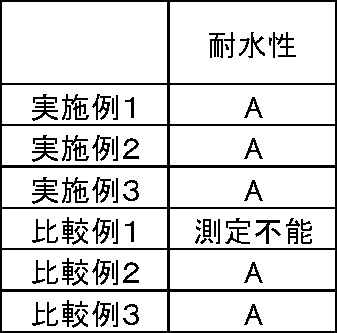
<<イオン吸着性能の評価>>
イオン吸着性能の評価は、実施例1~3及び比較例1~3の各結晶性ポリマー微孔性膜について、特開平2-187136号公報を参考にした。具体的には、10ppmの各金属イオン(銀、ナトリウム)含有水溶液を1L調製し、実施例1~3及び比較例1~3における各結晶性ポリマー微孔性膜に、該水溶液10mLを透過させ、透過後の水溶液中に含まれる金属イオン濃度を測定することにより行った。結果を表3に示す。
イオン吸着性能の評価は、実施例1~3及び比較例1~3の各結晶性ポリマー微孔性膜について、特開平2-187136号公報を参考にした。具体的には、10ppmの各金属イオン(銀、ナトリウム)含有水溶液を1L調製し、実施例1~3及び比較例1~3における各結晶性ポリマー微孔性膜に、該水溶液10mLを透過させ、透過後の水溶液中に含まれる金属イオン濃度を測定することにより行った。結果を表3に示す。

(実施例4)
-フィルターカートリッジ化-
ポリプロピレン不織布2枚の間に、実施例1で作製した結晶性ポリマー微孔性膜を挟んで、ひだ幅10.5mmにプリーツし、その138山分のひだをとって円筒状に丸め、その合わせ目をインパルスシーラーで溶着した。円筒の両端2mmずつを切り落とし、その切断面をポリプロピレン性のエンドプレートに熱溶着してエレメント交換式のフィルターカートリッジに仕上げた。
作製した本発明のフィルターカートリッジは、内蔵する結晶性ポリマー微孔性膜が親水性であるため、水系の処理において煩雑なプレ親水化処理が不要である。また、結晶性ポリマーを用いているため耐溶剤性に優れる。更に孔部が非対称構造を有するため、大流量かつ目詰まりを起こしにくく長寿命であった。
-フィルターカートリッジ化-
ポリプロピレン不織布2枚の間に、実施例1で作製した結晶性ポリマー微孔性膜を挟んで、ひだ幅10.5mmにプリーツし、その138山分のひだをとって円筒状に丸め、その合わせ目をインパルスシーラーで溶着した。円筒の両端2mmずつを切り落とし、その切断面をポリプロピレン性のエンドプレートに熱溶着してエレメント交換式のフィルターカートリッジに仕上げた。
作製した本発明のフィルターカートリッジは、内蔵する結晶性ポリマー微孔性膜が親水性であるため、水系の処理において煩雑なプレ親水化処理が不要である。また、結晶性ポリマーを用いているため耐溶剤性に優れる。更に孔部が非対称構造を有するため、大流量かつ目詰まりを起こしにくく長寿命であった。
本発明の結晶性ポリマー微孔性膜及びこれを用いた濾過用フィルタは、耐熱性及び耐薬品性に優れているため、濾過が必要とされる様々な状況において使用することができ、気体、液体等の精密濾過に好適に用いられ、例えば、電子工業用洗浄水、医薬用水、医薬製造工程用水、食品水等の濾過、滅菌、高温濾過などに幅広く用いることができる。
1 一次側サポート
2 精密ろ過膜
3 二次側サポート
4 上部エンドプレート
5 下部エンドプレート
6 フィルターエレメントカバー
7 フィルターエレメントコア
8 Oリング
9 フィルターメディア
10 フィルターエレメント
11 ハウジングカバー
12 ハウジングベース
13 液入口ノズル
14 液出口ノズル
15 エアーベント
16 ドレン
17 溶着部
101 外周カバー
102 膜サポート
103 精密ろ過膜
104 膜サポート
105 コアー
106a、106b エンドプレート
107 ガスケット
108 液体出口
2 精密ろ過膜
3 二次側サポート
4 上部エンドプレート
5 下部エンドプレート
6 フィルターエレメントカバー
7 フィルターエレメントコア
8 Oリング
9 フィルターメディア
10 フィルターエレメント
11 ハウジングカバー
12 ハウジングベース
13 液入口ノズル
14 液出口ノズル
15 エアーベント
16 ドレン
17 溶着部
101 外周カバー
102 膜サポート
103 精密ろ過膜
104 膜サポート
105 コアー
106a、106b エンドプレート
107 ガスケット
108 液体出口
Claims (11)
- 非対称孔構造を有する結晶性ポリマー微孔性膜であって、
前記結晶性ポリマー性微孔膜の露出表面の少なくとも一部が、ラジカル重合性モノマーを含む組成物を重合させてなるラジカル重合体で被覆され、前記ラジカル重合体の少なくとも一部に、イオン交換基及びキレート基の少なくともいずれかを含む官能性化合物が付加反応してなり、前記ラジカル重合性モノマーが、アクリレート、メタクリレート、アクリルアミド、アクリル酸及びこれらの誘導体から選択される少なくとも1種であることを特徴とする結晶性ポリマー微孔性膜。 - ラジカル重合性モノマーが、カルボキシル基、アミノ基、ヒドロキシル基、エポキシ基、アクリルアミド基、イソシアネート基、及び酸クロライド基の少なくともいずれかを含む請求項1に記載の結晶性ポリマー微孔性膜。
- 官能性化合物が、ラジカル重合体との反応性基を有する化合物である請求項1から2のいずれかに記載の結晶性ポリマー微孔性膜。
- 第1の面における平均孔径が、第2の面における平均孔径よりも大きく、かつ前記第1の面から前記第2の面に向かって平均孔径が連続的に変化する複数の孔部を有する請求項1から3のいずれかに記載の結晶性ポリマー微孔性膜。
- 露出表面にラジカル重合性モノマー重合体を被覆前の結晶性ポリマー微孔性膜の第1の面における平均孔径d3と、第2の面における平均孔径d4との比(d3/d4)と、
露出表面にフッ素系界面活性剤を被覆後の結晶性ポリマー微孔性膜の第1の面における平均孔径をd3’と、第2の面における平均孔径d4’との比(d3’/d4’)とが、次式、(d3’/d4’)/(d3/d4)>1、を満たす請求項1から4のいずれかに記載の結晶性ポリマー微孔性膜。 - 結晶性ポリマーが、ポリテトラフルオロエチレンである請求項1から5のいずれかに記載の結晶性ポリマー微孔性膜。
- 非対称孔構造を有する結晶性ポリマー微孔性膜の露出表面に、ラジカル重合性モノマーを含む組成物を付与し、該ラジカル重合性モノマーを重合させる親水化工程と、
前記ラジカル重合体の一部に、イオン交換基及びキレート基の少なくともいずれかを含む官能性化合物を付加反応させる付加反応処理工程とを含み、
前記ラジカル重合性モノマーが、アクリレート、メタクリレート、アクリルアミド、アクリル酸及びこれらの誘導体から選択される少なくとも1種であることを特徴とする結晶性ポリマー微孔性膜の製造方法。 - 結晶性ポリマーからなるフィルムの一の面を加熱して、該フィルムの厚み方向に温度勾配を形成した半焼成フィルムを形成する非対称加熱工程と、
前記半焼成フィルムを延伸して非対称孔構造を有する結晶性ポリマー微孔性膜を形成する延伸工程と、を更に含む請求項7に記載の結晶性ポリマー微孔性膜の製造方法。 - ラジカル重合性モノマーが、カルボキシル基、アミノ基、ヒドロキシル基、エポキシ基、アクリルアミド基、イソシアネート基、及び酸クロライド基の少なくともいずれかを含む請求項7から8のいずれかに記載の結晶性ポリマー微孔性膜の製造方法。
- 官能性化合物が、ラジカル重合体との反応性基を有する化合物である請求項7から9のいずれかに記載の結晶性ポリマー微孔性膜の製造方法。
- 請求項1から6のいずれかに記載の結晶性ポリマー微孔性膜を有することを特徴とする濾過用フィルタ。
Applications Claiming Priority (2)
| Application Number | Priority Date | Filing Date | Title |
|---|---|---|---|
| JP2011024200A JP2012161741A (ja) | 2011-02-07 | 2011-02-07 | 結晶性ポリマー微孔性膜及びその製造方法、並びに濾過用フィルタ |
| JP2011-024200 | 2011-10-21 |
Publications (1)
| Publication Number | Publication Date |
|---|---|
| WO2012108102A1 true WO2012108102A1 (ja) | 2012-08-16 |
Family
ID=46638331
Family Applications (1)
| Application Number | Title | Priority Date | Filing Date |
|---|---|---|---|
| PCT/JP2011/079147 Ceased WO2012108102A1 (ja) | 2011-02-07 | 2011-12-16 | 結晶性ポリマー微孔性膜及びその製造方法、並びに濾過用フィルタ |
Country Status (2)
| Country | Link |
|---|---|
| JP (1) | JP2012161741A (ja) |
| WO (1) | WO2012108102A1 (ja) |
Cited By (3)
| Publication number | Priority date | Publication date | Assignee | Title |
|---|---|---|---|---|
| US10040033B2 (en) | 2013-12-13 | 2018-08-07 | Toray Industries, Inc. | Multilayer separation membrane |
| JP2020528483A (ja) * | 2017-10-26 | 2020-09-24 | エルジー・ケム・リミテッド | フッ素系樹脂多孔性膜およびその製造方法 |
| WO2022229079A1 (de) * | 2021-04-26 | 2022-11-03 | Hengst Se | Verfahren zur herstellung eines flexiblen flachfaltenfilters mit hoher abscheidewirksamkeit und flachfaltenfilter |
Families Citing this family (3)
| Publication number | Priority date | Publication date | Assignee | Title |
|---|---|---|---|---|
| US20220040614A1 (en) * | 2018-09-28 | 2022-02-10 | Daikin Industries, Ltd. | Air filter medium, filter pack, air filter unit, and method for producing the same |
| WO2020075710A1 (ja) * | 2018-10-09 | 2020-04-16 | Jnc株式会社 | 微多孔膜を親水性にするためのコーティング組成物および親水性の微多孔膜 |
| JP2023516926A (ja) * | 2020-02-25 | 2023-04-21 | インテグリス・インコーポレーテッド | リガンド修飾フィルターおよび液体組成物から金属を減少させるための方法 |
Citations (6)
| Publication number | Priority date | Publication date | Assignee | Title |
|---|---|---|---|---|
| JPS6261619A (ja) * | 1985-09-10 | 1987-03-18 | Sumitomo Electric Ind Ltd | 液体膜 |
| JPS6348562B2 (ja) * | 1985-11-25 | 1988-09-29 | Sumitomo Electric Industries | |
| JP2005528213A (ja) * | 2002-06-07 | 2005-09-22 | ミリポア・コーポレイション | 耐腐食性かつ低い蛋白質結合性表面を有する多孔質膜基体 |
| JP2011011194A (ja) * | 2009-07-06 | 2011-01-20 | Fujifilm Corp | 結晶性ポリマー微孔性膜及びその製造方法、並びに濾過用フィルタ |
| JP2011104516A (ja) * | 2009-11-17 | 2011-06-02 | Fujifilm Corp | 結晶性ポリマー微孔性膜及びその製造方法、並びに濾過用フィルタ |
| JP2011110474A (ja) * | 2009-11-25 | 2011-06-09 | Fujifilm Corp | 濾過用フィルタ及びその製造方法 |
-
2011
- 2011-02-07 JP JP2011024200A patent/JP2012161741A/ja active Pending
- 2011-12-16 WO PCT/JP2011/079147 patent/WO2012108102A1/ja not_active Ceased
Patent Citations (6)
| Publication number | Priority date | Publication date | Assignee | Title |
|---|---|---|---|---|
| JPS6261619A (ja) * | 1985-09-10 | 1987-03-18 | Sumitomo Electric Ind Ltd | 液体膜 |
| JPS6348562B2 (ja) * | 1985-11-25 | 1988-09-29 | Sumitomo Electric Industries | |
| JP2005528213A (ja) * | 2002-06-07 | 2005-09-22 | ミリポア・コーポレイション | 耐腐食性かつ低い蛋白質結合性表面を有する多孔質膜基体 |
| JP2011011194A (ja) * | 2009-07-06 | 2011-01-20 | Fujifilm Corp | 結晶性ポリマー微孔性膜及びその製造方法、並びに濾過用フィルタ |
| JP2011104516A (ja) * | 2009-11-17 | 2011-06-02 | Fujifilm Corp | 結晶性ポリマー微孔性膜及びその製造方法、並びに濾過用フィルタ |
| JP2011110474A (ja) * | 2009-11-25 | 2011-06-09 | Fujifilm Corp | 濾過用フィルタ及びその製造方法 |
Non-Patent Citations (1)
| Title |
|---|
| JOSEPH E. GABRIELS: "Using A New, Fast Flow, Low Protein Binding Membranefor Sterile Filtration", APPLICATION NOTE, 2003, Retrieved from the Internet <URL:http://www.labplus.co.kr/tech/uploadHTML/millipore_Binding.pdf> * |
Cited By (4)
| Publication number | Priority date | Publication date | Assignee | Title |
|---|---|---|---|---|
| US10040033B2 (en) | 2013-12-13 | 2018-08-07 | Toray Industries, Inc. | Multilayer separation membrane |
| JP2020528483A (ja) * | 2017-10-26 | 2020-09-24 | エルジー・ケム・リミテッド | フッ素系樹脂多孔性膜およびその製造方法 |
| JP7060201B2 (ja) | 2017-10-26 | 2022-04-26 | エルジー・ケム・リミテッド | フッ素系樹脂多孔性膜およびその製造方法 |
| WO2022229079A1 (de) * | 2021-04-26 | 2022-11-03 | Hengst Se | Verfahren zur herstellung eines flexiblen flachfaltenfilters mit hoher abscheidewirksamkeit und flachfaltenfilter |
Also Published As
| Publication number | Publication date |
|---|---|
| JP2012161741A (ja) | 2012-08-30 |
Similar Documents
| Publication | Publication Date | Title |
|---|---|---|
| JP4863970B2 (ja) | 結晶性ポリマー微孔性膜及びその製造方法、並びに濾過用フィルタ | |
| JP5220698B2 (ja) | 結晶性ポリマー微孔性膜及びその製造方法、並びに濾過用フィルタ | |
| JP2011110474A (ja) | 濾過用フィルタ及びその製造方法 | |
| JP5528070B2 (ja) | 濾過フィルタ用結晶性ポリマー微孔性膜及びその製造方法、並びに濾過用フィルタ | |
| WO2012108102A1 (ja) | 結晶性ポリマー微孔性膜及びその製造方法、並びに濾過用フィルタ | |
| JP4937977B2 (ja) | 結晶性ポリマー微孔性膜及びその製造方法、並びに濾過用フィルタ | |
| JP2011110470A (ja) | 結晶性ポリマー微孔性膜及びその製造方法、並びに濾過用フィルタ | |
| JP2010058026A (ja) | 結晶性ポリマー微孔性膜及びその製造方法、並びに濾過用フィルタ | |
| US20130087500A1 (en) | Crystalline polymer microporous membrane, production method thereof, and filtration filter | |
| JP5399087B2 (ja) | 結晶性ポリマー微孔性膜、及びその製造方法、並びに、濾過用フィルタ | |
| JP2011072920A (ja) | 結晶性ポリマー微孔性膜及びその製造方法、並びに濾過用フィルタ | |
| JP5518442B2 (ja) | 濾過フィルタ用結晶性ポリマー微孔性膜及びその製造方法、並びに濾過用フィルタ | |
| JP5054745B2 (ja) | 結晶性ポリマー微孔性膜及びその製造方法、並びに濾過用フィルタ | |
| JP4850815B2 (ja) | 精密ろ過フィルター及びその製造方法 | |
| WO2012124759A1 (ja) | 結晶性ポリマー微孔性膜及びその製造方法、並びに濾過用フィルタ | |
| JP2011104516A (ja) | 結晶性ポリマー微孔性膜及びその製造方法、並びに濾過用フィルタ | |
| JP4850814B2 (ja) | 結晶性ポリマー微孔性膜及びその製造方法、並びに濾過用フィルタ | |
| JP2010058025A (ja) | 結晶性ポリマー微孔性膜及びその製造方法、並びに濾過用フィルタ | |
| JP2011104456A (ja) | 結晶性ポリマー微孔性膜及びその製造方法、並びに濾過用フィルタ | |
| JP2010172832A (ja) | 結晶性ポリマー微孔性膜、及びその製造方法、並びに、濾過用フィルタ | |
| JP2011102346A (ja) | 結晶性ポリマー微孔性膜及びその製造方法、並びに濾過用フィルタ | |
| JP5078729B2 (ja) | 結晶性ポリマー微孔性膜及びその製造方法、並びに濾過用フィルタ | |
| JP2009119411A (ja) | 結晶性ポリマー微孔性膜及びその製造方法、並びに濾過用フィルタ | |
| JP2011050908A (ja) | 結晶性ポリマー微孔性膜及びその製造方法、並びに濾過用フィルタ |
Legal Events
| Date | Code | Title | Description |
|---|---|---|---|
| 121 | Ep: the epo has been informed by wipo that ep was designated in this application |
Ref document number: 11858131 Country of ref document: EP Kind code of ref document: A1 |
|
| NENP | Non-entry into the national phase |
Ref country code: DE |
|
| 122 | Ep: pct application non-entry in european phase |
Ref document number: 11858131 Country of ref document: EP Kind code of ref document: A1 |