WO2012105291A1 - 受信装置、受信方法、通信システムおよび通信方法 - Google Patents
受信装置、受信方法、通信システムおよび通信方法 Download PDFInfo
- Publication number
- WO2012105291A1 WO2012105291A1 PCT/JP2012/050548 JP2012050548W WO2012105291A1 WO 2012105291 A1 WO2012105291 A1 WO 2012105291A1 JP 2012050548 W JP2012050548 W JP 2012050548W WO 2012105291 A1 WO2012105291 A1 WO 2012105291A1
- Authority
- WO
- WIPO (PCT)
- Prior art keywords
- channel impulse
- impulse response
- unit
- path
- estimation
- Prior art date
- Legal status (The legal status is an assumption and is not a legal conclusion. Google has not performed a legal analysis and makes no representation as to the accuracy of the status listed.)
- Ceased
Links
Images



Classifications
-
- H—ELECTRICITY
- H04—ELECTRIC COMMUNICATION TECHNIQUE
- H04L—TRANSMISSION OF DIGITAL INFORMATION, e.g. TELEGRAPHIC COMMUNICATION
- H04L25/00—Baseband systems
- H04L25/02—Details ; arrangements for supplying electrical power along data transmission lines
- H04L25/0202—Channel estimation
- H04L25/0212—Channel estimation of impulse response
-
- H—ELECTRICITY
- H04—ELECTRIC COMMUNICATION TECHNIQUE
- H04L—TRANSMISSION OF DIGITAL INFORMATION, e.g. TELEGRAPHIC COMMUNICATION
- H04L25/00—Baseband systems
- H04L25/02—Details ; arrangements for supplying electrical power along data transmission lines
- H04L25/0202—Channel estimation
- H04L25/022—Channel estimation of frequency response
-
- H—ELECTRICITY
- H04—ELECTRIC COMMUNICATION TECHNIQUE
- H04L—TRANSMISSION OF DIGITAL INFORMATION, e.g. TELEGRAPHIC COMMUNICATION
- H04L27/00—Modulated-carrier systems
- H04L27/26—Systems using multi-frequency codes
- H04L27/2601—Multicarrier modulation systems
- H04L27/2647—Arrangements specific to the receiver only
- H04L27/2649—Demodulators
Definitions
- the present invention relates to a receiving device, a receiving method, a communication system, and a communication method.
- propagation path estimation is performed by the receiving device in order to grasp the wireless propagation status. Since the receiving apparatus performs demodulation / decoding using the propagation path estimation result, the transmission characteristics are greatly degraded when the propagation path estimation accuracy is lowered. In order to perform highly accurate propagation path estimation, it is necessary to know the statistical properties of the propagation path.
- the statistical properties of the propagation path include the power of the path constituting the propagation path and the delay time with the path received in advance.
- FIG. 1 is an example of a channel impulse response that is a propagation path in the time domain, and arrows numbered 100-1 to 100-8 represent paths. Note that 100-4 and 100-5 mean delay times in which there is no substantial path, but here it is assumed that there is also a path with zero power at such a position.
- Non-Patent Document 1 describes a method for estimating all paths from a preceding path to a path with a delay time determined as propagation path estimation in scattered pilot OFDM. Taking FIG. 1 as an example, for example, paths 100-1 to 100-8 are estimated.
- the propagation path estimation value includes noise and interference correspondingly, and the estimation accuracy decreases.
- the present invention has been made in view of such circumstances, and an object of the present invention is to provide a receiving apparatus capable of highly accurate propagation path estimation.
- the receiving apparatus of the present invention includes a propagation path estimation unit that performs propagation path estimation, wherein the propagation path estimation unit calculates a temporary channel impulse response estimation value, and the temporary channel impulse response estimation value.
- a path extraction unit that extracts a path used for calculating a channel impulse response estimation value, and a channel impulse response estimation unit that calculates a channel impulse response estimation value using the path extracted by the path extraction unit;
- a frequency response estimator for performing time-frequency conversion on the channel impulse response estimated value and converting it to a frequency response estimated value.
- the path extraction unit may extract a predetermined number of paths in descending order of power of the temporary channel impulse response estimation value.
- the propagation path estimation unit may further include a selection unit that selects the best one from two or more channel impulse estimation values.
- the propagation path estimation unit may include a plurality of the path extraction unit and the channel impulse response estimation unit.
- the propagation path estimation unit may sequentially repeat the calculation of the channel impulse response estimation value.
- the path extraction unit may sequentially calculate the channel impulse response estimated value while reducing the number of extracted paths.
- the path extraction unit may sequentially calculate the channel impulse response estimation value while increasing the number of extraction paths.
- the propagation path estimation unit may end the estimation process when the channel impulse response estimation value is calculated a predetermined number of times.
- the selection unit may select the best estimated value using a Bayes information criterion.
- the accuracy of propagation path estimation can be greatly improved.
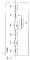
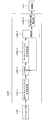
- FIG. 1 is a schematic block diagram of a transmission device according to a first embodiment of the present invention. It is a figure which shows the example to which the mapping part a104 maps a pilot symbol and a modulation signal. It is a schematic block diagram which shows the structure of the receiver b1 which concerns on the 1st Embodiment of this invention. It is a schematic block diagram which shows the structure of the propagation path estimation part b106. It is the schematic which shows an example of the received signal which concerns on the 1st Embodiment of this invention. It is a figure which shows an example of a delay profile.
- FIG. 2 is a schematic block diagram of the transmission apparatus according to the first embodiment of the present invention.
- the transmission device is a transmission device a1.
- a transmission device a1 is also called a pilot generation unit a101, a coding unit a102, a modulation unit a103, a mapping unit a104, an IFFT (Inverse Fast Fourier Transform) unit (inverse fast Fourier transform) unit (frequency time conversion unit). ) A105, a GI (Guard Interval) insertion unit a106, a transmission unit a107, and a transmission antenna a108, and transmits an OFDM signal.
- Pilot generating section a101 generates a pilot symbol in which the receiving apparatus stores in advance the amplitude value of the waveform (or signal sequence thereof) and outputs the pilot symbol to mapping section a104.
- the receiving device is referred to as a receiving device b1.
- the receiving apparatus b1 performs propagation path estimation using the pilot symbol as a reference signal.
- the encoding unit a102 encodes and encodes information bits to be transmitted to the receiving apparatus b1 using an error correction code such as a convolutional code, a turbo code, and an LDPC (Low Density Parity Check) code. Generate bits.
- the encoding unit a102 outputs the generated encoded bits to the modulating unit a103.
- the modulation unit a103 modulates the coded bits input from the coding unit a102 using a modulation method such as PSK (Phase Shift Keying) or QAM (Quadrature Amplitude Modulation), and converts the modulation symbol. Generate. Modulation section a103 outputs the generated modulation symbol to mapping section a104.
- a modulation method such as PSK (Phase Shift Keying) or QAM (Quadrature Amplitude Modulation
- the mapping unit a104 maps the pilot symbol input from the pilot generation unit a101 and the modulation symbol input from the modulation unit a103 to a resource (time-frequency band) based on predetermined mapping information.
- a domain signal is generated, and the generated frequency domain signal is output to IFFT section a105.
- a resource is a unit in which a modulation symbol is arranged, which is composed of one subcarrier and one FFT section described later in a frame transmitted by the transmission apparatus a1.
- the mapping information is determined by the transmission device a1, and is notified in advance from the transmission device a1 to the reception device b1.
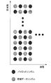
- FIG. 3 is an example in which the mapping unit a104 maps pilot symbols and modulated signals.
- a scattered pilot which is a discrete pilot arrangement, will be described as an example.
- the present invention is not limited to this and can be applied to other arrangements such as a preamble.
- the IFFT unit a105 performs frequency-time conversion on the frequency domain signal input from the mapping unit a104 to generate a time domain signal.
- a time interval of a unit for performing IFFT is referred to as an FFT interval.
- the IFFT unit a105 outputs the generated time domain signal to the GI insertion unit a106.
- the GI insertion unit a106 adds a GI for each signal in the FFT section to the time domain signal input from the IFFT unit a105.
- GI is a known signal using a cyclic prefix (Cyclic Prefix: CP), which is a part of the rear of the signal in the FFT section, zero padding in which the zero section continues, Golay code, or the like.
- CP Cyclic Prefix
- the GI insertion unit a106 adds such a signal to the front of the signal in the FFT interval.
- the FFT interval and the GI time interval (referred to as GI interval) added to the signal in the time interval by the GI insertion unit a106 are collectively referred to as an OFDM symbol interval.
- a signal in the OFDM symbol section is called an OFDM symbol.
- the GI insertion unit a106 outputs the signal with the GI added to the transmission unit a107.
- the GI may be inserted behind the FFT interval.
- a part of the replica in front of the FFT interval is added behind the signal in the FFT interval.
- the periodicity may be maintained in the OFDM symbol period, and is not limited to the above.
- the transmission unit a107 performs digital / analog conversion on the signal input from the GI insertion unit a106, and shapes the converted analog signal.
- the transmission unit a107 upconverts the waveform-shaped signal from the baseband to the radio frequency band, and transmits the signal from the transmission antenna a108 to the reception device b1.
- FIG. 4 is a schematic block diagram showing the configuration of the receiving device b1 according to this embodiment.
- a receiving device b1 includes a receiving antenna b101, a receiving unit b102, a GI removing unit b103, an FFT unit (also referred to as a time frequency converting unit) b104, a demapping unit b105, and a propagation path estimating unit b106.
- the reception unit b102 receives the transmission signal transmitted by the transmission device a1 via the reception antenna b101.
- the receiving unit b102 performs frequency conversion and analog / digital conversion on the received signal.
- the GI removal unit b103 removes the GI from the reception signal input from the reception unit b102 and outputs the GI to the FFT unit b104.
- the FFT unit b104 performs time frequency conversion on the time domain signal input from the GI removal unit b103, and outputs the converted frequency domain signal to the demapping unit b105.
- the demapping unit b105 performs demapping based on the mapping information notified in advance from the transmission device a1, and outputs the received signal of the subcarrier to which the separated pilot symbol is transmitted to the propagation path estimation unit b106. Also, the received signal of the subcarrier transmitted with data is output to demodulation section b107.
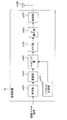
- FIG. 5 is a schematic block diagram showing the configuration of the propagation path estimation unit b106.
- a propagation path estimation unit b106 includes a temporary channel impulse response estimation unit b106-1, a path extraction unit 106-3, a channel impulse response estimation unit b106-4, a frequency response estimation unit b1-6-5, It is comprised including.
- Temporary channel impulse response estimation unit b106-1 estimates a frequency response based on the received signal input from demapping unit b105 and a pilot symbol stored in advance, and performs IFFT on the frequency response to estimate the temporary channel impulse response estimation value. Is calculated and output to the path extraction unit b106-3.
- Path extraction unit b106-3 among the tentative channel impulse response estimation value output from the temporary channel impulse response estimation unit B106-1, N to S path extraction in descending order of power. As a result, the path not selected is set to 0. The result is output to channel impulse response estimation section b106-4.
- the channel impulse response estimation unit b106-4 estimates the channel impulse response using the path extraction information output from the path extraction unit b106-3 and the temporary channel impulse response estimation value. This operation will be described in detail later.
- the channel impulse response estimation value is output to the frequency response estimation unit b106-5.
- the frequency response estimation unit b106-5 performs time-frequency conversion on the channel impulse response estimation value output from the channel impulse response estimation unit b106-4, and outputs the result to the demodulation unit b107.
- the propagation path estimation unit b106 uses a pilot symbol stored in advance, and measures noise power in a subcarrier (referred to as pilot subcarrier) in which the pilot symbol is arranged. A specific calculation method will be described later together with the operation principle.
- the demodulation unit b107 calculates filter coefficients such as ZF (Zero Forcing) standard and MMSE (Minimum Mean Square Error) standard using the frequency response and noise power input from the propagation path estimation unit b106.
- the demodulator b107 compensates for signal amplitude and phase fluctuations (referred to as propagation path compensation) using the calculated filter coefficients.
- the demodulator b107 outputs a bit log likelihood ratio (LLR) as a result of the demodulation process to the decoder b108.
- LLR bit log likelihood ratio
- the decoding unit b108 for example, performs maximum likelihood decoding (MLD; Maximum Likelihood Decoding), maximum a posteriori probability (MAP), log-MAP, Max- Decoding processing is performed using log-MAP, SOVA (Soft Output Viterbi Algorithm), or the like.
- MLD Maximum Likelihood Decoding
- MAP maximum a posteriori probability
- log-MAP maximum a posteriori probability
- Max- Decoding processing is performed using log-MAP, SOVA (Soft Output Viterbi Algorithm), or the like.
- FIG. 6 is a schematic diagram illustrating an example of a received signal according to the present embodiment.
- the maximum delay does not exceed the GI length and there is no interference due to the previous OFDM symbol.
- the horizontal axis is a time axis, which is a discrete time divided by a predetermined time width.
- a hatched area with diagonal lines rising diagonally to the right indicates GI.
- a hatched area with diagonal lines on the upper left represents received signals of the preceding and succeeding OFDM symbols.
- N is the number of points in the FFT (Fast Fourier Transform) section (also the number of points in the IFFT (Inverse Fast Fourier Transform) section), and N g is the number of GI points.
- the number of points is the number of discrete times.
- the reception signal r i, k of the i-th symbol at the k-th discrete time received by the reception unit b102 is expressed by the following equations (1) and (2).
- D is the maximum delay time
- h i d is the complex amplitude in the path of the channel number d of the i-th symbol (referred to as the d-th path)
- s i, k are the time domain of the i-th symbol k-th discrete time. This is a transmission signal
- z i, k is noise in the time domain of the i-th symbol.
- N is the number of points in the FFT interval
- S i, n is the modulation signal of the i-th symbol of the n-th subcarrier
- N g is the number of points in the GI interval (see FIG. 6)
- j is an imaginary unit.
- a signal R i, n after time-frequency conversion is performed on the received signal r i, k in the FFT section by the FFT unit b104 is expressed by the following equation (3).
- Z i, n is noise in the n-th subcarrier.
- H i, n is the frequency response of the i-th symbol and the n-th subcarrier, and is expressed by the following equation (4).
- the demodulator b107 calculates the demodulated symbol S ′ i, n using the following equation (5).
- Equation (5) ⁇ z 2 is the power of Z i, n and is expressed as in the following Equation (6).
- E [X] represents an ensemble average of X. This power can be calculated as in the following equation (7), and the result is used to calculate the demodulated symbol S ′ i, n using equation (5).
- Equation (7) is an estimated value of ⁇ z 2
- P i is a set representing pilot subcarriers in the i-th symbol. Note that this is a calculation method using the fact that Equation (7) can be expressed by the following Equation (8) when it is assumed that a sufficient number of arithmetic averages are equal to the ensemble average.
- This equation is for the case where the power of the pilot signal is normalized to 1 and the power average of the frequency response is normalized to 1. That is, this expression is a case where the following expression (9) is satisfied.
- the pilot signal power is not 1, an adjustment factor for that amount may be introduced. Further, the normalization of the frequency response is caused by amplitude adjustment when analog-to-digital conversion is performed in the receiving unit b102.
- the demodulator b107 calculates a bit log likelihood ratio from the demodulated symbol S ′ i, n in Expression (5).
- An equivalent amplitude gain is used for this calculation process.
- the bit log likelihood ratio ⁇ is expressed by the following equations (11) and (12) with respect to the equivalent amplitude gain ⁇ i, n of the n-th subcarrier expressed by the following equation (10). ).
- the equations (11) and (12) are respectively expressed as the bit log likelihood ratios ⁇ (b i, n, 0 ) of the first bit b i, n, 0 and the second bit b i, n, 1 . 0 ), ⁇ (b i, n, 1 ).
- Temporary channel impulse response estimation section b 106-1 first calculates an estimated value H ′ i, n of the frequency response based on equation (3). Specifically, it estimates like following Formula (13).
- the signal S i, n of the nth subcarrier needs to be known, but a pilot symbol or the like may be used.
- n 1 , n 2 ,..., n P pilot subcarriers, frequency response estimation vector
- n 1 is the lowest subcarrier
- n 2 is the next subcarrier
- n 3 is the next subcarrier
- NP is the number of pilot subcarriers
- L is an assumed maximum delay time, which may be fixed when the receiving device b1 is developed, or variable at the design stage, and updated when updating the firmware, software, etc. of the receiving device b1. May be equal.
- Each element of represents a correlation between paths.
- This is a diagonal matrix of size L + 1 with the value of the average power of the path from 0 to L in the main diagonal element, and represents the delay profile.
- FIG. 7 is an example of a delay profile, and there is no path at the positions of path numbers 3, 4, 8, and 9.
- the temporary channel impulse response estimation unit b106-1 performs IFFT on Hi , P shown in Expression (14) as shown in the following Expression (19).
- reference numerals 801 to 810 denote paths. Compared to FIG. 7, due to the influence of noise and interference, the number and arrangement of pilot signals, etc., it is observed that there are paths such as 804, 805, 809, and 810 even at positions where there are no paths in FIG. 7.
- the path extractor B106-3 among these paths, N S path selecting a high power order.
- the value of N S may be previously decided when designing the receiving apparatus b1, in the design phase leave the variable, the reception device b1 firmware, may be equal to update when updating software, etc. .
- the frequency response estimation unit b106-5 performs time-frequency conversion on the channel impulse response estimated value obtained by Expression (20), and converts it to a frequency response estimated value for demodulation.
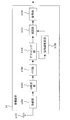
- FIG. 9 is a flowchart showing the operation of the receiving apparatus according to this embodiment. The operation shown in this figure is processing after the receiving unit b102 in FIG. 4 outputs the received signal to the GI removing unit b103.
- Step S101 The GI removing unit b103 removes the GI from the received signal. Then, it progresses to step S102.
- Step S102 The FFT unit b104 performs time-frequency conversion on the signal obtained in Step S101.
- the demapping unit b105 separates data and pilot from the obtained frequency domain signal. After outputting the received signal of the pilot subcarrier to the propagation path estimation unit b106, the process proceeds to step S103.
- Step S103 The temporary channel impulse response estimation unit b106-1 in the propagation path estimation unit b106 calculates a temporary channel impulse response estimation value using the received signal of the pilot subcarrier obtained in step S102. After the estimated value is output to the path extraction unit b106-3, the process proceeds to step S104.
- Step S104 The path extraction unit b106-3 performs path extraction using the temporary channel impulse response estimation value obtained in step S103, and outputs the result to the channel impulse response estimation unit b106-4. Thereafter, the process proceeds to step S105.
- Step S105 The channel impulse response estimation unit b106-4 calculates a channel impulse response estimation value using the path information obtained in step S104. Thereafter, the process proceeds to step S106.
- Step S106 The frequency response estimation unit b106-5 performs time-frequency conversion on the channel impulse response estimated value obtained in Step S105, and converts it to a frequency response estimated value. Thereafter, the process proceeds to step S107.
- Step S107 The demodulation unit b107 performs a demodulation process using the frequency response estimation value obtained in Step S106. Thereafter, the process proceeds to step S108.
- Step S108 The decoding unit b108 performs decoding using the demodulation result obtained in step S107. Thereafter, the receiving device b1 ends the operation.
- the propagation path estimation unit b106 calculates the temporary channel impulse response estimated value by performing IFFT on the frequency response estimated value of the pilot subcarrier, extracts the path with the higher power, A channel impulse response estimation value is calculated using the path information. In this way, the degree of freedom can be used for noise / interference suppression as much as the estimation unnecessary path is not used, and the propagation path estimation accuracy can be improved.
- the frequency response is estimated using a pilot symbol for each OFDM symbol has been described.
- interpolation may be performed using a pilot symbol of a nearby OFDM symbol.
- the pilot subcarrier is located at the lowest subcarrier, the second subcarrier, the second subcarrier,... Locations that are not subcarriers may also be estimated using pilot symbols of OFDM symbols having different times.
- noise and interference can be reduced by using pilot symbols at different times. In this way, the propagation path estimation accuracy can be further improved. Specifically, when the propagation path fluctuation is not large, an arithmetic average may be performed, or a weighted average may be performed according to the propagation path fluctuation.
- pilot symbols are used as reference signals used for frequency response estimation.
- estimation may be performed using determined data. Specifically, this can be realized by feeding back the output of the demodulator b107 or the decoder b108 to the temporary channel impulse response estimator b106-1.
- the communication system has been described for the case of performing multicarrier signal communication.
- the present invention is not limited to this, and is also applicable to the case of performing single carrier signal communication using FFT. can do.
- the calculated channel impulse response estimated value is converted into a frequency response estimated value to perform demodulation processing.
- the time domain demodulation processing is performed using the channel impulse response estimated value. Also good. For example, when performing the above-described single carrier signal communication, time-domain demodulation can be performed.
- the transmission device a1 transmits a multicarrier signal or the like that maps pilot symbols in the frequency domain, and the reception device b1 calculates a frequency response estimation value in the pilot subcarrier, and performs IFFT on it. Then, a temporary channel impulse response estimation value was calculated, a path with high power was extracted, and a channel impulse response estimation value was calculated using the path.
- a method will be described in which the above-described channel impulse response estimation is attempted with a plurality of extraction paths and the optimum one is selected.
- the transmission device a2 according to the second embodiment of the present invention is the same as the transmission device a1 according to the first embodiment, the description thereof is omitted.
- FIG. 10 is a schematic block diagram showing the configuration of the receiving device b2 according to the second embodiment of the present invention.
- the processing of the propagation path estimation unit b206 is different.
- the functions of other components (receiving antenna b101, receiving unit b102, GI removing unit b103, FFT unit b104, demapping unit b105, demodulating unit b107, decoding unit b108) are the same as those in the first embodiment. .
- a description of the same functions as those in the first embodiment is omitted.
- FIG. 11 is a schematic block diagram showing the configuration of the propagation path estimation unit b206.
- the propagation path estimation unit b206 includes a temporary channel impulse response estimation unit b106-1, path extraction units b206-3-1 to b206-3-M, and channel impulse response estimation units b206-4-1 to b206-4. -M, selection section b206-6, and frequency response estimation section b106-5.
- the operations of the temporary channel impulse response estimation unit b106-1 and the frequency response estimation unit b106-5 are the same as those of the propagation path estimation unit b106 (FIG. 5) of the first embodiment. A description of the same functions as those in the first embodiment is omitted.
- the propagation path estimation unit b206 estimates M channel impulse responses. Let N S (m) be the number of extraction paths when estimating the m-th channel impulse response. The estimated number M and the extracted path number N s (m) may be fixed at the stage of development of the receiving device b2, or may be made variable at the design stage, and updated when updating the firmware, software, etc. of the receiving device b2. You may do it.
- the path extraction unit b206-3-M extracts N s (m) paths in descending order of power from the temporary channel impulse response estimation values output from the temporary channel impulse response estimation unit b106-1.
- the processing flow of the temporary channel impulse response estimation unit b206-1-M to the channel impulse response estimation unit b206-4-M is the same as that of the temporary channel impulse response estimation unit b106-1 to channel impulse response estimation unit b106 in the first embodiment. -4 (FIG. 5). However, the number of extraction paths is N s (m).
- the selection unit b206-6 compares the M channel impulse response estimation values estimated by the channel impulse response estimation units b206-4-1 to b206-4-M, selects the best one, and selects the best frequency response estimation unit b106. Output to -5. This process will be described later together with the operation principle.
- the frequency response estimation unit b106-5 performs time-frequency conversion on the channel impulse response estimation value output from the selection unit b206-6 to convert it into a frequency response estimation value for demodulation, and outputs it to the demodulation unit b107.
- the channel impulse response estimation unit b206-4-M outputs the channel impulse response estimation value.
- the first term is an evaluation value of the error between the temporary channel impulse response and the channel impulse response
- the second term is a penalty for increasing the number of estimated paths.
- the equation (21) is an example of an amount indicating an error evaluation value and a goodness due to a penalty, and other criteria such as an AIC including an error evaluation value and a penalty may be used.
- the selection unit b206-6 selects the channel impulse response estimation value corresponding to m that maximizes f (m).
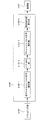
- FIG. 12 is a flowchart showing the operation of the receiving apparatus according to this embodiment. The operation shown in this figure is processing after the reception unit b102 in FIG. 10 outputs the reception signal to the GI removal unit b103.
- Step S201 The GI removing unit b103 removes the GI from the received signal. Thereafter, the process proceeds to step S202.
- Step S202 The FFT unit b104 performs time-frequency conversion on the signal obtained in Step S201.
- the demapping unit b105 separates data and pilot from the obtained frequency domain signal. After outputting the reception signal of the pilot subcarrier to the propagation path estimation unit b206, the process proceeds to step S203.
- Step S203 The temporary channel impulse response estimation unit b106-1 in the propagation path estimation unit b206 calculates a temporary channel impulse response estimation value using the received signal of the pilot subcarrier obtained in step S202. After the estimated value is output to the path extraction units b206-3-1 to b206-3-M, the process proceeds to step S204.
- Step S204 The path extraction unit b206-3-M performs path extraction using the temporary channel impulse response estimation value obtained in step S203, and outputs the result to the channel impulse response estimation unit b206-4-M. Thereafter, the process proceeds to step S205.
- Step S205 The channel impulse response estimation unit b206-4-M calculates a channel impulse response estimated value using the path information obtained in step S204. Thereafter, the process proceeds to step S206.
- Step S206 The selection unit b206-6 compares the M channel impulse response estimation values obtained in step S205, selects the best one, and outputs it to the frequency response estimation unit b106-5. Thereafter, the process proceeds to step S207.
- Step S207 The frequency response estimation unit b106-5 performs time-frequency conversion on the channel impulse response estimation value obtained in Step S206, and converts it to a frequency response estimation value. Thereafter, the process proceeds to step S208.
- Step S208 The demodulation unit b107 performs demodulation processing using the frequency response estimation value obtained in Step S207. Thereafter, the process proceeds to step S209.
- Step S209 The decoding unit b108 performs decoding using the demodulation result obtained in step S208. Thereafter, the receiving device b2 ends the operation.
- the propagation path estimation unit b206 calculates the temporary channel impulse response estimated value by performing IFFT on the frequency response estimated value of the pilot subcarrier, extracts the path with the higher power, A channel impulse response estimation value is calculated using the path information.
- channel impulse response estimation values obtained by using a plurality of extraction paths are compared, and the best one is selected. In this way, the degree of freedom can be used for noise / interference suppression as much as the estimation unnecessary path is not used, and the propagation path estimation accuracy can be improved.
- the transmission device a1 transmits a multicarrier signal or the like that maps pilot symbols in the frequency domain, and the reception devices b1 and b2 calculate frequency response estimation values in pilot subcarriers. Then, IFFT is used to calculate a provisional channel impulse response estimated value, and a plurality of processes of extracting a path having a large power among them are performed, and the best one is selected, and the channel using the selected extraction path is selected. Impulse response was calculated. In this embodiment, first, all the paths from the preceding path to the assumed maximum delay time are estimated, and from there, the process of reducing the number of paths is performed. adopt.
- the transmission apparatus according to the third embodiment of the present invention is the same as the transmission apparatus a1 according to the first embodiment, description thereof is omitted.
- FIG. 13 is a schematic block diagram showing the configuration of the receiving device b3 according to the third embodiment of the present invention.
- the processing of the propagation path estimation unit b306 is different.
- the functions of other components (receiving antenna b101, receiving unit b102, GI removing unit b103, FFT unit b104, demapping unit b105, demodulating unit b107, decoding unit b108) are the same as those in the first embodiment. .
- a description of the same functions as those in the first embodiment is omitted.
- FIG. 14 is a schematic block diagram showing the configuration of the propagation path estimation unit b306.
- the operations of the path extracting unit b306-3 and the channel impulse response estimating unit b306-4 are as follows. Differently, a selection unit b306-6 is added.
- the operations of the temporary channel impulse response estimation unit b106-1 and the frequency response estimation unit b106-5 are the same as those of the propagation path estimation unit b106 (FIG. 5) of the first embodiment. A description of the same functions as those in the first embodiment is omitted.
- the propagation path estimation unit b306 repeats the operations of the path extraction unit b306-3, the channel impulse response estimation unit b306-4, and the selection unit b306-6 until the best result is obtained.
- the path extraction unit b306-3 sets the number of first extracted paths from the preceding path to the assumed maximum delay time L. As in the first embodiment, this value may be fixed when the receiving device b3 is developed, or may be changed at the design stage, and updated when the firmware, software, etc. of the receiving device b3 are updated. May be. In iterative process, from the previous extraction path number, the number of reduced N i pass the extracted path number.
- the channel impulse response estimation unit b306-4 calculates a channel impulse response estimation value based on the path position information output from the path extraction unit b306-3.
- the selection unit b306-6 performs no operation at the first time, and issues a command to reduce the number of extracted paths to the path extraction unit. Further, the channel impulse response estimation value output from the channel impulse response estimation unit b306-4 is stored. In the iterative process, the channel impulse response estimation value output from the channel impulse response estimation unit b306-4 and the channel impulse response estimation value stored in the selection unit b306-6 are compared based on Expression (21). As a result, if the stored value is better, the estimation process ends here, and the stored channel impulse response estimated value is output to the frequency response estimating unit b106-5. If the stored value is worse, issue an instruction to reduce the number of extracted paths to the path extraction unit, store the channel impulse response estimation value that is the output of the channel impulse response estimation unit b306-4, and continue the iterative process To do.
- channel impulse response estimation section b306-4 calculates a channel impulse response estimation value based on the path information. Estimate value for k-th trial
- FIG. 15 is a flowchart showing the operation of the receiving apparatus according to this embodiment. The operation shown in this figure is a process after the reception unit b102 in FIG. 13 outputs the reception signal to the GI removal unit b103.
- Step S301 The GI removing unit b103 removes the GI from the received signal. Thereafter, the process proceeds to step S302.
- Step S302 The FFT unit b104 performs time-frequency conversion on the signal obtained in Step S301.
- the demapping unit b105 separates data and pilot from the obtained frequency domain signal. After the reception signal of the pilot subcarrier is output to the propagation path estimation unit b106, the process proceeds to step S303.
- Step S303 The temporary channel impulse response estimation unit b106-1 in the propagation path estimation unit b306 calculates a temporary channel impulse response estimation value using the received signal of the pilot subcarrier obtained in step S302. After the estimated value is output to the path extraction unit b306-3, the process proceeds to step S304.
- Step S304 The path extraction unit b306-3 performs path extraction using the temporary channel impulse response estimation value obtained in step S303, and outputs the result to the channel impulse response estimation unit b306-4. Thereafter, the process proceeds to step S305.
- Step S305 The channel impulse response estimation unit b306-4 calculates a channel impulse response estimation value using the path information obtained in step S304. Thereafter, the process proceeds to step S306.
- Step S306 The selection unit b306-6 compares the channel impulse response estimation value obtained in step S305 with the channel impulse response estimation value stored in the selection unit b306-6. Thereafter, the process proceeds to step S307.
- Step S307 As a result of Step S306, if the channel impulse response estimated value obtained in Step S305 is better than the channel impulse response estimated value stored in the selecting unit b306-6, the selecting unit b306-6 stores The channel impulse response estimated value being discarded is discarded, and the channel impulse response estimated value obtained in step S305 is stored. In addition, the number of extraction paths of the path extraction unit b306-3 is decreased. Thereafter, the process proceeds to step S305.
- the channel impulse response estimation value stored in the selection unit b306-6 is output to the frequency response estimation unit b106-5, and the process proceeds to step S308.
- Step S308 The frequency response estimation unit b106-5 performs time-frequency conversion on the channel impulse response estimated value obtained in Step S307, and converts it to a frequency response estimated value. Thereafter, the process proceeds to step S309.
- Step S309 The demodulation unit b107 performs demodulation processing using the channel impulse response estimated value obtained in Step S308. Thereafter, the process proceeds to step S310.
- Step S310 The decoding unit b108 performs decoding using the demodulation result obtained in step S309. Thereafter, the receiving device b3 ends the operation.
- the propagation path estimation unit b306 calculates the provisional channel impulse response estimated value by performing the IFFT on the frequency response estimated value of the pilot subcarrier, and from the preceding path to the assumed maximum delay first. Calculate the channel impulse response estimate using all the paths, then repeat the calculation of the channel impulse response estimate with the number of paths reduced, finish the process with the best number of paths, and obtain the best channel impulse response estimate. obtain. In this way, the degree of freedom can be used for noise / interference suppression as much as the estimation unnecessary path is not used, and the propagation path estimation accuracy can be improved. In the present embodiment, since the optimal number of paths can be determined adaptively to the environment, it is possible to cope with changes in the environment at a high level.
- the method of sequentially repeating the calculation of the channel impulse response estimation value while reducing the number of extraction paths has been described.
- the number may be increased from a small number.
- the channel impulse response estimation value is calculated with a small number of extracted paths, and the number of extracted paths is increased in the process of being repeated thereafter.
- the method for sequentially repeating the calculation of the channel impulse response estimation value while reducing the number of extraction paths has been described.
- the method may be stopped halfway.
- the maximum number of repetitions is determined in advance, and when that number is reached, the process proceeds to step S308 regardless of the result of step S307.
- a part of the transmission device a1 and the reception devices b1 to b3, for example, the propagation path estimation unit b106 and the demodulation unit b107 in the above-described embodiment may be realized by a computer.
- the program for realizing the control function may be recorded on a computer-readable recording medium, and the program recorded on the recording medium may be read into the computer system and executed.
- the “computer system” here is a computer system built in the transmission device a1 or the reception devices b1 to b3, and includes an OS and hardware such as peripheral devices.
- the “computer-readable recording medium” refers to a storage device such as a portable medium such as a flexible disk, a magneto-optical disk, a ROM, and a CD-ROM, and a hard disk built in the computer system.
- the “computer-readable recording medium” is a medium that dynamically holds a program for a short time, such as a communication line when transmitting a program via a network such as the Internet or a communication line such as a telephone line,
- a volatile memory inside a computer system that serves as a server or a client may be included that holds a program for a certain period of time.
- the program may be a program for realizing a part of the functions described above, and may be a program capable of realizing the functions described above in combination with a program already recorded in a computer system.
- a part or all of the transmission device a1 and the reception devices b1 to b3 in the above-described embodiment may be realized as an integrated circuit such as an LSI (Large Scale Integration).
- LSI Large Scale Integration
- Each functional block of the transmission device a1 and the reception devices b1 to b3 may be individually made into a processor, or a part or all of them may be integrated into a processor.
- the method of circuit integration is not limited to LSI, and may be realized by a dedicated circuit or a general-purpose processor. Further, in the case where an integrated circuit technology that replaces LSI appears due to progress in semiconductor technology, an integrated circuit based on the technology may be used.
- a1 Transmitting device a101 Pilot generating unit a102 Encoding unit a103 Modulating unit a104 Mapping unit a105 IFFT unit a106 GI inserting unit a107 Transmitting / receiving unit a108 Transmitting antenna b1, b2, b3 Receiving device b101 Receiving antenna b102 Receiving unit b103 GI removing unit b104 FFT unit b105 Demapping unit b106, b206, b306 Propagation path estimation unit b107 Demodulation unit b108 Decoding unit b106-1 Temporary channel impulse response estimation unit b106-3, b206-3-1 to b206-3-M, b306-3 Path extraction unit b106 -4, b206-4-1 to b206-4-M, b306-4 Channel impulse response estimator b106-5 Frequency response estimator b206-6, b306-6 Selector All publications cited in this specification, Patents and patents issued As it is intended to incorporate herein by reference.
Landscapes
- Engineering & Computer Science (AREA)
- Power Engineering (AREA)
- Computer Networks & Wireless Communication (AREA)
- Signal Processing (AREA)
- Noise Elimination (AREA)
Abstract
伝搬路推定を行う伝搬路推定部(b106)を備え、前記伝搬路推定部は、仮チャネルインパルス応答推定値を算出する仮チャネルインパルス応答推定部(b106-1)と、前記仮チャネルインパルス応答推定値を構成するパスのうち、チャネルインパルス応答推定値の算出に用いるパスを抽出するパス抽出部(b106-3)と、前記パス抽出部が抽出したパスを用いて前記チャネルインパルス応答推定値を算出するチャネルインパルス応答推定部(b106-4)と前記チャネルインパルス応答推定値に時間周波数変換を施し、周波数応答推定値に変換する周波数応答推定部(b106-5)とを備える。これにより高精度な伝搬路推定が可能な受信装置を提供することができる。
Description
本発明は、受信装置、受信方法、通信システムおよび通信方法に関する。
無線通信の分野では、受信装置で無線伝搬状況を把握するために伝搬路推定を行っている。受信装置は伝搬路推定結果を用いて復調・復号を行うため、伝搬路推定精度が低下すると、伝送特性が大きく劣化する。高精度な伝搬路推定を行うためには、伝搬路の統計的性質を知っている必要がある。伝搬路の統計的性質には、伝搬路を構成するパスの電力や、先行して受信されるパスとの遅延時間といったものがある。図1は、時間領域の伝搬路であるチャネルインパルス応答の一例であり、100-1~100-8で番号付けされた矢印がパスを表す。なお、100-4と100-5は、実質パスの存在しない遅延時間を意味するが、ここではそのような位置も電力0のパスがあるものとする。
非特許文献1には、スキャッタード・パイロットOFDMにおける伝搬路推定として、先行パスから決められた遅延時間のパスまでのパスをすべて推定する方法が記載されている。図1を例にすると、例えば、パス100-1~100-8までを推定する。
S.Suyama、M.Ito、K.Fukawa、H.Suzuki、「A Scattered Pilot OFDM Receiver Employing Turbo ICI Cancellation in Fast Fading Environments」、IEICE Trans.Commun.、Vol.E88-B、No.1、2005年1月
しかしながら、非特許文献1の方法では、伝搬路推定に不要なパスも推定しているため、伝搬路推定値にはその分だけ雑音、干渉が含まれ、推定精度が低下する。本発明はこのような事情に鑑みてなされたものであり、その目的は、高精度な伝搬路推定が可能な受信装置を提供することにある。
本発明の受信装置は、伝搬路推定を行う伝搬路推定部を備え、前記伝搬路推定部は、仮チャネルインパルス応答推定値を算出する仮チャネルインパルス応答推定部と、前記仮チャネルインパルス応答推定値を構成するパスのうち、チャネルインパルス応答推定値の算出に用いるパスを抽出するパス抽出部と、前記パス抽出部が抽出したパスを用いてチャネルインパルス応答推定値を算出するチャネルインパルス応答推定部と、前記チャネルインパルス応答推定値に時間周波数変換を施し、周波数応答推定値に変換する周波数応答推定部とを備えることを特徴とする。
前記パス抽出部は、前記仮チャネルインパルス応答推定値の電力の大きい順に事前に定められた数のパスを抽出するようにしてもよい。
前記伝搬路推定部は、2つ以上の前記チャネルインパルス推定値から最良のものを選択する選択部をさらに備えてもよい。
前記伝搬路推定部は、前記パス抽出部と前記チャネルインパルス応答推定部とを複数備えてもよい。
前記伝搬路推定部は、前記チャネルインパルス応答推定値の算出を逐次的に繰り返すようにしてもよい。
前記パス抽出部は、抽出パス数を減らしながら逐次的に前記チャネルインパルス応答推定値を算出していくようにしてもよい。
前記パス抽出部は、抽出パス数を増やしながら逐次的に前記チャネルインパルス応答推定値を算出していくようにしてもよい。
前記伝搬路推定部は、事前に決められた回数の前記チャネルインパルス応答推定値の算出を行った場合、推定処理を終了するようにしてもよい。
前記選択部は、ベイズ情報量基準を用いて最良の推定値を選択するようにしてもよい。
本明細書は本願の優先権の基礎である日本国特許出願2011-021528号の明細書および/または図面に記載される内容を包含する。
本発明によれば、伝搬路推定の精度を大きく向上することができる。
(第1の実施形態)
図2は、本発明の第1の実施形態に係る送信装置の概略ブロック図である。以下、本実施形態では、送信装置を送信装置a1とする。この図において、送信装置a1は、パイロット生成部a101と、符号部a102と、変調部a103と、マッピング部a104と、IFFT(Inverse Fast Fourier Transform:逆高速フーリエ変換)部(周波数時間変換部とも呼ぶ)a105と、GI(Guard Interval:ガードインターバル)挿入部a106と、送信部a107と、送信アンテナa108とを含んで構成され、OFDM信号を送信する。
図2は、本発明の第1の実施形態に係る送信装置の概略ブロック図である。以下、本実施形態では、送信装置を送信装置a1とする。この図において、送信装置a1は、パイロット生成部a101と、符号部a102と、変調部a103と、マッピング部a104と、IFFT(Inverse Fast Fourier Transform:逆高速フーリエ変換)部(周波数時間変換部とも呼ぶ)a105と、GI(Guard Interval:ガードインターバル)挿入部a106と、送信部a107と、送信アンテナa108とを含んで構成され、OFDM信号を送信する。
パイロット生成部a101は、受信装置がその波形(あるいは、その信号系列)の振幅値を予め記憶するパイロットシンボルを生成し、マッピング部a104に出力する。なお、以下、本実施形態では、受信装置を受信装置b1とする。受信装置b1では、パイロットシンボルを参照信号として伝搬路推定を行う。
符号部a102は、受信装置b1に送信する情報ビットに対して、畳込み符号、ターボ符号、LDPC(Low Density Parity Check:低密度パリティ検査)符号などの誤り訂正符号を用いて符号化し、符号化ビットを生成する。符号部a102は、生成した符号化ビットを変調部a103に出力する。
変調部a103は、符号部a102から入力された符号化ビットを、PSK(Phase Shift Keying:位相変調)やQAM(Quadrature Amplitude Modulation:直交振幅変調)などの変調方式を用いて変調し、変調シンボルを生成する。変調部a103は、生成した変調シンボルをマッピング部a104に出力する。
マッピング部a104は、パイロット生成部a101から入力されたパイロットシンボルと、変調部a103から入力された変調シンボルとを、予め定められたマッピング情報に基づいてリソース(時間-周波数帯域)にマッピングして周波数領域の信号を生成し、生成した周波数領域の信号をIFFT部a105に出力する。なお、リソースとは、送信装置a1が送信するフレームにおいて1つのサブキャリアと1つの後述するFFT区間から成る、変調シンボルを配置する単位である。また、マッピング情報は、送信装置a1が決定し、送信装置a1から受信装置b1へ予め通知される。図3は、マッピング部a104がパイロットシンボルと変調信号をマッピングする例である。なお、本実施形態では離散的なパイロット配置であるスキャッタード・パイロットを例に説明するが、本発明はこれに限らず、プリアンブルなどその他の配置でも適用可能である。
IFFT部a105は、マッピング部a104から入力された周波数領域の信号を周波数-時間変換し、時間領域の信号を生成する。ここで、IFFTを行う単位の時間区間をFFT区間という。IFFT部a105は、生成した時間領域の信号をGI挿入部a106に出力する。
GI挿入部a106は、IFFT部a105から入力された時間領域の信号に対して、FFT区間の信号毎にGIを付加する。ここで、GIとは、FFT区間の信号の後方の一部を複製したものであるサイクリックプレフィックス(Cyclic Prefix:CP)やゼロ区間が続くゼロパディング、Golay符号等を用いた既知信号等であり、GI挿入部a106は、このような信号をこのFFT区間の信号の前方に付加する。
なお、FFT区間と、GI挿入部a106がその時間区間の信号に付加したGIの時間区間(GI区間という)とを併せてOFDMシンボル区間という。また、OFDMシンボル区間の信号をOFDMシンボルという。GI挿入部a106は、GIを付加した信号を送信部a107に出力する。
なお、GIをFFT区間の後方に挿入してもよい。例えば、サイクリックプレフィックスを用いる場合、FFT区間の前方の一部の複製をFFT区間の信号の後方に付加する。また、サイクリックプレフィックスの場合は、OFDMシンボル区間で周期性が保たれるようにすればよく、前記の限りではない。
送信部a107は、GI挿入部a106から入力された信号をデジタル・アナログ変換し、変換したアナログ信号を波形整形する。送信部a107は、波形整形した信号をベースバンド帯から無線周波数帯にアップコンバートし、送信アンテナa108から受信装置b1へ送信する。
図4は、本実施形態に係る受信装置b1の構成を示す概略ブロック図である。この図において、受信装置b1は、受信アンテナb101と、受信部b102と、GI除去部b103と、FFT部(時間周波数変換部とも呼ぶ)b104と、デマッピング部b105と、伝搬路推定部b106と、復調部b107と、復号部b108とを含んで構成される。
受信部b102は、送信装置a1が送信した送信信号を、受信アンテナb101を介して受信する。受信部b102は、受信した信号に対して、周波数変換およびアナログ・デジタル変換を行う。
GI除去部b103は、受信部b102から入力された受信信号からGIを除去し、FFT部b104へ出力する。
FFT部b104は、GI除去部b103から入力された時間領域の信号に対して時間周波数変換を行い、変換した周波数領域の信号をデマッピング部b105へ出力する。
デマッピング部b105は、送信装置a1から予め通知されたマッピング情報に基づいてデマッピングし、分離されたパイロットシンボルが送信されたサブキャリアの受信信号を伝搬路推定部b106に出力する。また、データ送信されたサブキャリアの受信信号を復調部b107に出力する。
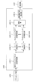
図5は、伝搬路推定部b106の構成を示す概略ブロック図である。この図において、伝搬路推定部b106は、仮チャネルインパルス応答推定部b106-1と、パス抽出部106-3と、チャネルインパルス応答推定部b106-4と、周波数応答推定部b1-6-5とを含んで構成される。
仮チャネルインパルス応答推定部b106-1は、デマッピング部b105から入力された受信信号と、予め記憶するパイロットシンボルとに基づいて周波数応答を推定し、それにIFFTを施すことで仮チャネルインパルス応答推定値を算出し、パス抽出部b106-3に出力する。
パス抽出部b106-3は、仮チャネルインパルス応答推定部b106-1から出力された仮チャネルインパルス応答推定値のうち、電力の高い順にNSパス抽出する。この結果、選ばれなかったパスは0にする。結果をチャネルインパルス応答推定部b106-4に出力する。
チャネルインパルス応答推定部b106-4は、パス抽出部b106-3から出力されたパス抽出情報と仮チャネルインパルス応答推定値とを用いてチャネルインパルス応答を推定する。この動作は詳しく後述する。チャネルインパルス応答推定値を周波数応答推定部b106-5に出力する。
周波数応答推定部b106-5は、チャネルインパルス応答推定部b106-4から出力されたチャネルインパルス応答推定値に時間周波数変換を施し、復調部b107に出力する。
また、伝搬路推定部b106は、予め記憶するパイロットシンボルを用い、パイロットシンボルが配置されるサブキャリア(パイロットサブキャリアという)において、雑音電力を測定する。具体的な算出方法は、動作原理と合わせて後述する。
復調部b107は、伝搬路推定部b106から入力された周波数応答および雑音電力を用いて、ZF(Zero Forcing)基準、MMSE(Minimum Mean Square Error)基準等のフィルタ係数を算出する。復調部b107は、算出したフィルタ係数を用いて、信号の振幅と位相の変動の補償(伝搬路補償という)を行う。
復調部b107は、復調処理の結果のビット対数尤度比(LLR;Log Likelihood Ratio)を復号部b108に出力する。
復号部b108は、復調部b107から入力された復調シンボルに対して、例えば、最尤復号法(MLD;Maximum Likelihood Decoding)、最大事後確率(MAP;Maximum A posteriori Probability)、log-MAP、Max-log-MAP、SOVA(Soft Output Viterbi Algorithm)等を用いて復号処理を行う。
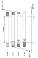
図6は、本実施形態に係る受信信号の一例を示す概略図である。この図において、最大遅延はGI長を超えず、前のOFDMシンボルによる干渉は無い。
この図において、横軸は時間軸であり、予め定めた時間幅で区切られた離散時刻である。この図において、右斜め上がりの斜線でハッチングした領域はGIを示す。また、左斜め上の斜線でハッチングした領域は前後のOFDMシンボルの受信信号を表す。
また、NはFFT(Fast Fourier Transform;フーリエ変換)区間のポイント数(IFFT(Inverse Fast Fourier Transform;逆フーリエ変換)区間のポイント数でもある)、NgはGIのポイント数である。ここで、ポイント数とは離散時刻の数である。
<動作原理について>
以下、受信装置b1の動作原理について、図4を参照しながら説明する。
以下、受信装置b1の動作原理について、図4を参照しながら説明する。
受信部b102が受信した第k離散時刻の第iシンボルの受信信号ri,kは、次式(1)、(2)で表される。


ここで、Dは最大遅延時間、hi,dは第iシンボルの伝搬路番号dのパス(第dパスという)における複素振幅、si,kは第iシンボル第k離散時刻の時間領域の送信信号であり、zi,kは第iシンボルの時間領域の雑音である。また、NはFFT区間のポイント数、Si,nは第nサブキャリアの第iシンボルの変調信号、NgはGI区間のポイント数(図6参照)、jは虚数単位である。なお、d=0~Dの複素振幅をまとめて、チャネルインパルス応答という。
FFT区間の受信信号ri,kに対して、FFT部b104にて、時間周波数変換を行った後の信号Ri,nは、次式(3)で表される。

ここで、Zi,nは第nサブキャリアにおける雑音である。また、Hi,nは、第iシンボル第nサブキャリアの周波数応答であり、次式(4)で表される。

ここでは、推定値が得られているものとして、受信装置b1の残りの機能を説明する。復調部b107は、例えばMMSE基準のフィルタリングを用いた場合、復調シンボルS’i,nを次式(5)を用いて算出する。

ここで、Y*は、Yの複素共役であることを示す。また、式(5)において、σz
2はZi,nの電力であり、次式(6)のように表される。

ここで、E[X]は、Xのアンサンブル平均を示す。なお、この電力は次式(7)のように計算することができ、その結果を式(5)を用いて復調シンボルS’i,nを算出する。

ここで、σz’2はσz
2の推定値であり、Piは第iシンボルにおいてパイロットサブキャリアを表す集合である。なお、これは十分な数の算術平均がアンサンブル平均に等しいと仮定した場合、式(7)が次式(8)のようにできることを利用した算出法である。

この式は、パイロット信号の電力が1に正規化され、周波数応答の電力平均が1に正規化される場合のものである。すなわち、この式は次式(9)が満たされる場合のものである。

なお、パイロット信号の電力が1でない場合は、その分の調整係数を導入すればよい。また、周波数応答の正規化は、受信部b102にてアナログ-デジタル変換されるときの振幅調整に起因する。
復調部b107は、式(5)の復調シンボルS’i,nからビット対数尤度比を算出する。この算出処理には等価振幅利得が用いられる。具体的には、QPSKの場合、次式(10)で表される第nサブキャリアの等価振幅利得μi,nに対して、ビット対数尤度比λは、次式(11)、(12)で表される。ここで、式(11)、(12)は、それぞれ1ビット目のビットbi,n,0、2ビット目のビットbi,n,1のビット対数尤度比λ(bi,n,0)、λ(bi,n,1)である。

次に伝搬路推定の動作を説明する。仮チャネルインパルス応答推定部b106-1は、まず、式(3)に基づいて周波数応答の推定値H’i,nを算出する。具体的には、次式(13)のように推定する。
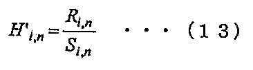
これを行うためには、第nサブキャリアの信号Si,nが既知である必要があるが、パイロットシンボル等を用いればよい。
ここで、周波数応答の推定値からチャネルインパルス応答を推定する方法について説明する。n1、n2、・・・、nPをパイロットサブキャリアとして、周波数応答推定ベクトル

を次式(14)のように定義する。

ただし、太字はベクトル又は行列を表し、

は

の転置を表す。なお、例えば図3における最初のOFDMシンボルを考えると、n1は一番低いサブキャリア、n2はそれより2つ先のサブキャリア、n3はさらに2つ先のサブキャリア、・・・、ということになる。このとき、MMSEによりチャネルインパルス応答推定ベクトル

は、次式(15)、(16)のようになる。

ただし、NPはパイロットサブキャリア数であり、

はサイズxの単位行列である。また、Lは想定する最大遅延時間であり、受信装置b1を開発した段階で固定してもよいし、設計段階では可変にしておき、受信装置b1のファームウェア、ソフトウェア等をアップデートするときに更新する等してもよい。なお、
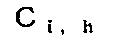
の各要素はパス間の相関を表す。
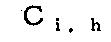
は次式(18)のような仮定を置くことが多い。
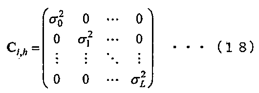
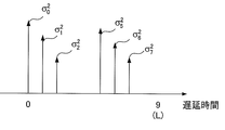
これは、主対角要素に0~Lまでのパスの平均電力の値を持つサイズL+1の対角行列であり、遅延プロファイルを表す。図7は、遅延プロファイルの一例であり、パス番号3、4、8、9の位置にはパスは存在しない。
実際にはこのような

が未知であるので、別の方法で推定する。具体的に、仮チャネルインパルス応答推定部b106-1において、式(14)で示すHi,Pに対して次式(19)のようにIFFTを行う。

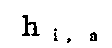
は仮チャネルインパルス応答推定値であり、図8のようになる。図8において、801~810はパスを表す。図7と比較すると、雑音および干渉の影響や、パイロット信号の数および配置等により、図7ではパスの無い位置においても804、805、809、810のようにパスがあるように観測される。パス抽出部b106-3では、これらパスのうち、電力の高い順にNSパス選択する。NSの値は、受信装置b1を設計したときに決めておいてもよいし、設計段階では可変にしておき、受信装置b1のファームウェア、ソフトウェア等をアップデートするときに更新する等してもよい。
次に、チャネルインパルス応答推定部b106-4の動作を説明する。ここでは、図8において、NS=7として説明する。選ばれるパスは801~803、805~808である。式(15)により、チャネルインパルス応答の推定ベクトル
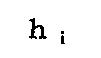
は次式(20)のようになる。

ただし、

は式(18)において、σ0
2=σ1
2=σ2
2=σ4
2=σ5
2=σ6
2=σ7
2=α、σ3
2=σ8
2=σ9
2=0とした行列である。なお、必ずしも式(20)の通りに計算する必要はなく、逆行列の補助定理を用いて計算量を削減してもよい。
次に周波数応答推定部b106-5は、式(20)で得られるチャネルインパルス応答推定値に時間周波数変換を施し、復調用の周波数応答推定値に変換する。
<受信装置b1の動作について>
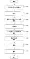
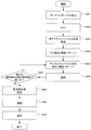
図9は、本実施形態に係る受信装置の動作を示すフローチャートである。なお、この図が示す動作は、図4の受信部b102が受信信号をGI除去部b103に出力した後の処理である。
図9は、本実施形態に係る受信装置の動作を示すフローチャートである。なお、この図が示す動作は、図4の受信部b102が受信信号をGI除去部b103に出力した後の処理である。
(ステップS101)GI除去部b103は、受信信号からGIを除去する。その後、ステップS102へ進む。
(ステップS102)FFT部b104は、ステップS101で得られる信号に対して時間周波数変換を行う。デマッピング部b105は、得られた周波数領域の信号から、データとパイロットを分離する。パイロットサブキャリアの受信信号を伝搬路推定部b106に出力した後、ステップS103へ進む。
(ステップS103)伝搬路推定部b106における仮チャネルインパルス応答推定部b106-1は、ステップS102で得られるパイロットサブキャリアの受信信号を用いて仮チャネルインパルス応答推定値を算出する。推定値をパス抽出部b106-3に出力した後、ステップS104へ進む。
(ステップS104)パス抽出部b106-3は、ステップS103で得られた仮チャネルインパルス応答推定値を用いてパス抽出を行い、結果をチャネルインパルス応答推定部b106-4に出力する。その後、ステップS105に進む。
(ステップS105)チャネルインパルス応答推定部b106-4は、ステップS104で得られるパス情報を用いてチャネルインパルス応答推定値を算出する。その後、ステップS106へ進む。
(ステップS106)周波数応答推定部b106-5は、ステップS105で得られたチャネルインパルス応答推定値に時間周波数変換を施し、周波数応答推定値に変換する。その後、ステップS107に進む。
(ステップS107)復調部b107は、ステップS106で得られる周波数応答推定値を用い、復調処理を行う。その後、ステップS108へ進む。
(ステップS108)復号部b108は、ステップS107で得られる復調結果を用いて復号を行う。その後、受信装置b1は動作を終了する。
このように、本実施形態によれば、伝搬路推定部b106は、パイロットサブキャリアの周波数応答推定値をIFFTして仮チャネルインパルス応答推定値を算出し、そのうち電力の高いパスを抽出し、そのパス情報を用いてチャネルインパルス応答推定値を算出する。このようにすると推定不要のパスを使わなかった分、自由度を雑音・干渉の抑圧に用いることができ、伝搬路推定精度を向上させることができる。
なお、上記第1の実施形態において、OFDMシンボル毎にパイロットシンボルを用いて周波数応答を推定する場合について説明したが、近傍のOFDMシンボルのパイロットシンボルを用いて補間してもよい。例えば、図3の最初のOFDMシンボルにおいては、パイロットサブキャリアの位置は一番低いサブキャリア、2つ先のサブキャリア、さらに2つ先のサブキャリア、・・・、となっているが、パイロットサブキャリアでない場所についても時刻の異なるOFDMシンボルのパイロットシンボルを用いて推定してもよい。また、パイロットシンボルのあるサブキャリアに関しても、異なる時刻のパイロットシンボルを用いることで、雑音・干渉を低減することができる。このようにすることで、伝搬路推定精度をさらに改善できる。具体的には、伝搬路変動が大きくない場合には算術平均を行ってもよいし、伝搬路変動に合わせて重み付け平均を行ってもよい。
なお、上記第1の実施形態において、周波数応答の推定に用いる参照信号として、パイロットシンボルを用いて行う場合について説明したが、判定したデータを用いて推定してもよい。具体的には、復調部b107又は復号部b108の出力を仮チャネルインパルス応答推定部b106-1にフィードバックすること等で実現できる。
なお、上記第1の実施形態において、通信システムはマルチキャリア信号の通信を行う場合について説明したが、本発明はこれに限らず、FFTを用いてシングルキャリア信号の通信を行う場合にも、適用することができる。
なお、上記第1の実施形態において、算出したチャネルインパルス応答推定値を周波数応答推定値に変換して復調処理を行っているが、チャネルインパルス応答推定値を用いて時間領域の復調処理を行ってもよい。例えば、上述のシングルキャリア信号の通信を行う場合、時間領域の復調を行うことができる。
(第2の実施形態)
以下、図面を参照しながら本発明の第2の実施形態について詳しく説明する。前記第1の実施形態では、送信装置a1がパイロットシンボルを周波数領域にマッピングするマルチキャリア信号等を送信し、受信装置b1が、パイロットサブキャリアにおいて周波数応答推定値を算出し、それをIFFTすることで仮チャネルインパルス応答推定値を算出し、そのうち電力の大きいパスを抽出し、そのパスを用いてチャネルインパルス応答推定値を算出した。本実施形態では、抽出パス数を複数で上記のチャネルインパルス応答推定を試行し、最適なものを選択する方法について説明する。
以下、図面を参照しながら本発明の第2の実施形態について詳しく説明する。前記第1の実施形態では、送信装置a1がパイロットシンボルを周波数領域にマッピングするマルチキャリア信号等を送信し、受信装置b1が、パイロットサブキャリアにおいて周波数応答推定値を算出し、それをIFFTすることで仮チャネルインパルス応答推定値を算出し、そのうち電力の大きいパスを抽出し、そのパスを用いてチャネルインパルス応答推定値を算出した。本実施形態では、抽出パス数を複数で上記のチャネルインパルス応答推定を試行し、最適なものを選択する方法について説明する。
本発明の第2の実施形態に係る送信装置a2は、第1の実施形態に係る送信装置a1と同一であるため、説明を省略する。
図10は、本発明の第2の実施形態に係る受信装置b2の構成を示す概略ブロック図である。本実施形態に係る受信装置b2(図10)と第1の実施形態に係る受信装置b1(図4)とを比較すると、伝搬路推定部b206の処理が異なる。しかし、その他の構成要素(受信アンテナb101、受信部b102、GI除去部b103、FFT部b104、デマッピング部b105、復調部b107、復号部b108)が持つ機能は第1の実施形態と同じである。第1の実施形態と同じ機能の説明は省略する。
図11は、伝搬路推定部b206の構成を示す概略ブロック図である。この図において、伝搬路推定部b206は、仮チャネルインパルス応答推定部b106-1、パス抽出部b206-3-1~b206-3-M、チャネルインパルス応答推定部b206-4-1~b206-4-M、選択部b206-6、周波数応答推定部b106-5から構成される。仮チャネルインパルス応答推定部b106-1と周波数応答推定部b106-5の動作は、第1の実施形態の伝搬路推定部b106(図5)と同じである。第1の実施形態と同じ機能の説明は省略する。
伝搬路推定部b206は、M通りのチャネルインパルス応答を推定する。m番目のチャネルインパルス応答を推定する際の抽出パス数をNS(m)とする。推定数Mと抽出パス数Ns(m)は受信装置b2を開発した段階で固定にしてもよいし、設計段階では可変にしておき、受信装置b2のファームウェア、ソフトウェア等をアップデートするときに更新する等してもよい。
パス抽出部b206-3-Mは、仮チャネルインパルス応答推定部b106-1から出力される仮チャネルインパルス応答推定値のうち、電力の高い順にNs(m)パス抽出する。
仮チャネルインパルス応答推定部b206-1-M~チャネルインパルス応答推定部b206-4-Mの処理の流れは、第1の実施形態における仮チャネルインパルス応答推定部b106-1~チャネルインパルス応答推定部b106-4まで(図5)と同様である。ただし、抽出パス数はNs(m)である。
選択部b206-6は、チャネルインパルス応答推定部b206-4-1~b206-4-Mで推定されたM個のチャネルインパルス応答推定値を比較し、最も良いものを選んで周波数応答推定部b106-5に出力する。この処理は動作原理と併せて後述する。
周波数応答推定部b106-5は、選択部b206-6から出力されるチャネルインパルス応答推定値に時間周波数変換を施して復調用の周波数応答推定値に変換し、復調部b107に出力する。
<動作原理について>
以下、受信装置b2の伝搬路推定部b206の動作原理について、図11を参照しながら説明する。
以下、受信装置b2の伝搬路推定部b206の動作原理について、図11を参照しながら説明する。
チャネルインパルス応答推定部b206-4-Mが出力するチャネルインパルス応答推定値を

とする。選択部b206-6は、
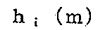
と仮チャネルインパルス応答推定ベクトル

と抽出パス数Ns(m)を用いて最良の推定値を示すmを選択する。ここでは、その比較にBIC(ベイズ情報量基準;Bayesian Information Criterion)を用いる場合について説明する。
m番目の推定値に対するBICの値f(m)は次式(21)のようになる。

第1項は、仮チャネルインパルス応答とチャネルインパルス応答との誤差の評価値であり、第2項は推定パス数が多くなることへのペナルティである。なお、式(21)は誤差の評価値とペナルティによる良さを示す量の一例であり、誤差の評価値とペナルティからなるAIC等の他の基準を用いてもよい。
選択部b206-6は、f(m)を最大にするmに対応するチャネルインパルス応答推定値
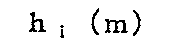
を周波数応答推定部b106-5に出力する。
<受信装置b2の動作について>
図12は、本実施形態に係る受信装置の動作を示すフローチャートである。なお、この図が示す動作は、図10の受信部b102が受信信号をGI除去部b103に出力した後の処理である。
図12は、本実施形態に係る受信装置の動作を示すフローチャートである。なお、この図が示す動作は、図10の受信部b102が受信信号をGI除去部b103に出力した後の処理である。
(ステップS201)GI除去部b103は、受信信号からGIを除去する。その後、ステップS202へ進む。
(ステップS202)FFT部b104は、ステップS201で得られる信号に対して時間周波数変換を行う。デマッピング部b105は、得られた周波数領域の信号から、データとパイロットを分離する。パイロットサブキャリアの受信信号を伝搬路推定部b206に出力した後、ステップS203へ進む。
(ステップS203)伝搬路推定部b206における仮チャネルインパルス応答推定部b106-1は、ステップS202で得られるパイロットサブキャリアの受信信号を用いて仮チャネルインパルス応答推定値を算出する。推定値をパス抽出部b206-3-1~b206-3-Mに出力した後、ステップS204へ進む。
(ステップS204)パス抽出部b206-3-Mは、ステップS203で得られる仮チャネルインパルス応答推定値を用いてパス抽出を行い、結果をチャネルインパルス応答推定部b206-4-Mに出力する。その後、ステップS205に進む。
(ステップS205)チャネルインパルス応答推定部b206-4-Mは、ステップS204で得られるパス情報を用いてチャネルインパルス応答推定値を算出する。その後、ステップS206に進む。
(ステップS206)選択部b206-6は、ステップS205で得られるM通りのチャネルインパルス応答推定値を比較し、最良のものを選択して周波数応答推定部b106-5に出力する。その後、ステップS207に進む。
(ステップS207)周波数応答推定部b106-5は、ステップS206で得られるチャネルインパルス応答推定値に時間周波数変換を施し、周波数応答推定値に変換する。その後、ステップS208へ進む。
(ステップS208)復調部b107は、ステップS207で得られる周波数応答推定値を用い、復調処理を行う。その後、ステップS209へ進む。
(ステップS209)復号部b108は、ステップS208で得られる復調結果を用いて復号を行う。その後、受信装置b2は動作を終了する。
このように、本実施形態によれば、伝搬路推定部b206は、パイロットサブキャリアの周波数応答推定値をIFFTして仮チャネルインパルス応答推定値を算出し、そのうち電力の高いパスを抽出し、そのパス情報を用いてチャネルインパルス応答推定値を算出する。また、複数の抽出パス数を用いて得られるチャネルインパルス応答推定値を比較し、最良のものを選択する。このようにすると推定不要のパスを使わなかった分、自由度を雑音・干渉の抑圧に用いることができ、伝搬路推定精度を向上させることができる。本実施形態においては、複数の抽出パス数で考慮するため、環境の変化にも対応できる。
なお、上記の説明では、図11のようにM種類のパス抽出処理を並列に動作させるものとして説明したが、直列にして順番に処理するようにしてもよい。
(第3の実施形態)
以下、図面を参照しながら本発明の第3の実施形態について詳しく説明する。前記第2の実施形態の伝搬路推定部では、送信装置a1がパイロットシンボルを周波数領域にマッピングするマルチキャリア信号等を送信し、受信装置b1およびb2が、パイロットサブキャリアにおいて周波数応答推定値を算出し、それをIFFTすることで仮チャネルインパルス応答推定値を算出し、そのうち電力の大きいパスを抽出するという処理を複数行い、その中で最良のものを選び、選ばれた抽出パスを用いてチャネルインパルス応答を算出した。本実施形態では、まず、先行パスから想定する最大遅延時間までのパスをすべて推定し、そこからパス数を減らす処理を行って、その方がよいという結果が出れば減らした方を抽出パスとして採用する。
以下、図面を参照しながら本発明の第3の実施形態について詳しく説明する。前記第2の実施形態の伝搬路推定部では、送信装置a1がパイロットシンボルを周波数領域にマッピングするマルチキャリア信号等を送信し、受信装置b1およびb2が、パイロットサブキャリアにおいて周波数応答推定値を算出し、それをIFFTすることで仮チャネルインパルス応答推定値を算出し、そのうち電力の大きいパスを抽出するという処理を複数行い、その中で最良のものを選び、選ばれた抽出パスを用いてチャネルインパルス応答を算出した。本実施形態では、まず、先行パスから想定する最大遅延時間までのパスをすべて推定し、そこからパス数を減らす処理を行って、その方がよいという結果が出れば減らした方を抽出パスとして採用する。
本発明の第3の実施形態に係る送信装置は、第1の実施形態に係る送信装置a1と同一であるため、説明を省略する。
図13は、本発明の第3の実施形態に係る受信装置b3の構成を示す概略ブロック図である。本実施形態に係る受信装置b3(図13)と第1の実施形態に係る受信装置b1(図4)とを比較すると、伝搬路推定部b306の処理が異なる。しかし、その他の構成要素(受信アンテナb101、受信部b102、GI除去部b103、FFT部b104、デマッピング部b105、復調部b107、復号部b108)が持つ機能は第1の実施形態と同じである。第1の実施形態と同じ機能の説明は省略する。
図14は、伝搬路推定部b306の構成を示す概略ブロック図である。受信装置b3における伝搬路推定部b306(図14)と受信装置b1における伝搬路推定部b106(図5)とを比較すると、パス抽出部b306-3とチャネルインパルス応答推定部b306-4の動作が異なり、選択部b306-6が追加されている。仮チャネルインパルス応答推定部b106-1と周波数応答推定部b106-5の動作は、第1の実施形態の伝搬路推定部b106(図5)と同じである。第1の実施形態と同じ機能の説明は省略する。
伝搬路推定部b306では、パス抽出部b306-3、チャネルインパルス応答推定部b306-4、選択部b306-6の動作を、最良の結果が得られるまで繰り返す。
パス抽出部b306-3は、初回の抽出パス数は、先行パスから想定する最大遅延時間Lまですべてとする。第1の実施形態と同様、この値は受信装置b3を開発した段階で固定してもよいし、設計段階では可変にしておき、受信装置b3のファームウェア、ソフトウェア等をアップデートするときに更新する等してもよい。繰り返し処理では、前回の抽出パス数より、Niパス減らした数を抽出パス数とする。
チャネルインパルス応答推定部b306-4は、パス抽出部b306-3から出力されるパス位置の情報に基づいてチャネルインパルス応答推定値を算出する。
選択部b306-6は、初回は何も動作を行わず、パス抽出部に抽出パス数を減らす命令を出す。また、チャネルインパルス応答推定部b306-4から出力されるチャネルインパルス応答推定値を記憶する。繰り返し処理では、チャネルインパルス応答推定部b306-4から出力されるチャネルインパルス応答推定値と、選択部b306-6が記憶しているチャネルインパルス応答推定値とを式(21)に基づいて比較する。この結果、記憶している値の方が良かった場合、ここで推定処理を終了し、記憶しているチャネルインパルス応答推定値を周波数応答推定部b106-5に出力する。記憶している値の方が悪かった場合、パス抽出部に抽出パス数を減らす命令を出し、チャネルインパルス応答推定部b306-4の出力であるチャネルインパルス応答推定値を記憶し、繰り返し処理を続行する。
<動作原理について>
以下、受信装置b3の伝搬路推定部b306の動作原理について、図14を参照しながら説明する。また、仮チャネルインパルス応答推定部b106-1の出力である仮チャネルインパルス応答推定値

以下、受信装置b3の伝搬路推定部b306の動作原理について、図14を参照しながら説明する。また、仮チャネルインパルス応答推定部b106-1の出力である仮チャネルインパルス応答推定値
の例として図8を用いて説明する。
パス抽出部b306-3において、初回は先行パスから想定する最大遅延までのパスすべてを抽出するため、図8におけるパス801~810が抽出される。k番目の試行で抽出したパスの番号を保存したベクトルを

とする。上記より、k=0が初回処理を表わすものとすると、

である。
次に、チャネルインパルス応答推定部b306-4は、そのパス情報に基づいてチャネルインパルス応答推定値を算出する。k番目の試行における推定値を
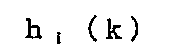
とする。
選択部b306-6は、
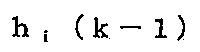
と
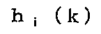
とを比較する。このときの比較基準は式(21)を用いればよい。
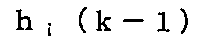
の方が良かった場合、
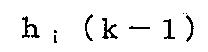
を周波数応答部b106-5に出力して推定処理を終了する。
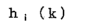
の方が良かった場合、選択部b306-6で保存している

を破棄して
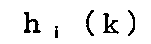
を保存する。次に、パス抽出部b306-3に抽出パス数を減らす命令を出し、k+1番目の試行に移行する。
パス抽出部b306-3は、選択部b306-6から抽出パス数を減らす命令を受けた場合、

で表わされるパスのうち、

の値が小さいパスを削除する。残ったパス位置を新たな抽出パス
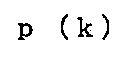
とする。例えば、図8においてk=1の試行を考える。この場合、
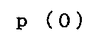
は801~810までである。このうち、削除するパス数を2とすると、削除するパスは809と810になり、

となる。以後は、上記チャネルインパルス応答推定部b306-4からの動作を繰り返す。
<受信装置b3の動作について>
図15は、本実施形態に係る受信装置の動作を示すフローチャートである。なお、この図が示す動作は、図13の受信部b102が受信信号をGI除去部b103に出力した後の処理である。
図15は、本実施形態に係る受信装置の動作を示すフローチャートである。なお、この図が示す動作は、図13の受信部b102が受信信号をGI除去部b103に出力した後の処理である。
(ステップS301)GI除去部b103は、受信信号からGIを除去する。その後、ステップS302へ進む。
(ステップS302)FFT部b104は、ステップS301で得られる信号に対して時間周波数変換を行う。デマッピング部b105は、得られた周波数領域の信号から、データとパイロットを分離する。パイロットサブキャリアの受信信号を伝搬路推定部b106に出力した後、ステップS303へ進む。
(ステップS303)伝搬路推定部b306における仮チャネルインパルス応答推定部b106-1は、ステップS302で得られるパイロットサブキャリアの受信信号を用いて仮チャネルインパルス応答推定値を算出する。推定値をパス抽出部b306-3に出力した後、ステップS304へ進む。
(ステップS304)パス抽出部b306-3は、ステップS303で得られる仮チャネルインパルス応答推定値を用いてパス抽出を行い、結果をチャネルインパルス応答推定部b306-4に出力する。その後、ステップS305に進む。
(ステップS305)チャネルインパルス応答推定部b306-4は、ステップS304で得られるパス情報を用いてチャネルインパルス応答推定値を算出する。その後、ステップS306に進む。
(ステップS306)選択部b306-6は、ステップS305で得られるチャネルインパルス応答推定値と、選択部b306-6が保存しているチャネルインパルス応答推定値とを比較する。その後、ステップS307に進む。
(ステップS307)ステップS306の結果、ステップS305で得られたチャネルインパルス応答推定値の方が、選択部b306-6の保存するチャネルインパルス応答推定値よりも良かった場合、選択部b306-6は保存しているチャネルインパルス応答推定値を破棄し、ステップS305で得られるチャネルインパルス応答推定値を保存する。また、パス抽出部b306-3の抽出パス数を減少させる。その後、ステップS305に進む。
条件を満たさない場合は、選択部b306-6の保存するチャネルインパルス応答推定値を周波数応答推定部b106-5に出力し、ステップS308に進む。
(ステップS308)周波数応答推定部b106-5は、ステップS307で得られるチャネルインパルス応答推定値に時間周波数変換を施し、周波数応答推定値に変換する。その後、ステップS309に進む。
(ステップS309)復調部b107は、ステップS308で得られるチャネルインパルス応答推定値を用いて復調処理を行う。その後、ステップS310へ進む。
(ステップS310)復号部b108は、ステップS309で得られる復調結果を用いて復号を行う。その後、受信装置b3は動作を終了する。
このように、本実施形態によれば、伝搬路推定部b306は、パイロットサブキャリアの周波数応答推定値をIFFTして仮チャネルインパルス応答推定値を算出し、まず先行パスから想定する最大遅延までのパス全てを用いてチャネルインパルス応答推定値を算出し、そこからパス数を減らしてのチャネルインパルス応答推定値の算出を繰り返し、最も良いパス数で処理を終了し、最良のチャネルインパルス応答推定値を得る。このようにすると推定不要のパスを使わなかった分、自由度を雑音・干渉の抑圧に用いることができ、伝搬路推定精度を向上させることができる。本実施形態においては、環境に最適なパス数を適応的に決められるため、環境の変化に高度に対応できる。
なお、上記第3の実施形態において、抽出パス数を減らしながらチャネルインパルス応答推定値の算出を逐次的に繰り返す方法について説明したが、少ない数から増やすようにしてもよい。例えば、初回の推定では少ない抽出パス数でチャネルインパルス応答推定値の算出を行い、その後繰り返す過程で抽出パス数を増加させていく。
なお、上記第3の実施形態において、抽出パス数を減らしながらチャネルインパルス応答推定値の算出を逐次的に繰り返す方法について説明したが、途中で止めてもよい。例えば、事前に最大繰り返し回数を定めておき、その回数に達した場合は、ステップS307の結果によらず、ステップS308に進むようにする。
なお、上述した実施形態における送信装置a1及び受信装置b1~b3の一部、例えば、伝搬路推定部b106、復調部b107をコンピュータで実現するようにしてもよい。その場合、この制御機能を実現するためのプログラムをコンピュータ読み取り可能な記録媒体に記録して、この記録媒体に記録されたプログラムをコンピュータシステムに読み込ませ、実行することによって実現してもよい。
なお、ここでいう「コンピュータシステム」とは、送信装置a1又は受信装置b1~b3に内蔵されたコンピュータシステムであって、OSや周辺機器等のハードウェアを含むものとする。さらに、「コンピュータ読み取り可能な記録媒体」とは、フレキシブルディスク、光磁気ディスク、ROM、CD-ROM等の可搬媒体、コンピュータシステムに内蔵されるハードディスク等の記憶装置のことをいう。さらに「コンピュータ読み取り可能な記録媒体」とは、インターネット等のネットワークや電話回線等の通信回線を介してプログラムを送信する場合の通信線のように、短時間、動的にプログラムを保持するもの、その場合のサーバやクライアントとなるコンピュータシステム内部の揮発性メモリのように、一定時間プログラムを保持しているものも含んでもよい。また上記プログラムは、前述した機能の一部を実現するためのものであってもよく、さらに前述した機能をコンピュータシステムにすでに記録されているプログラムとの組み合わせで実現できるものであってもよい。
また、上述した実施形態における送信装置a1及び受信装置b1~b3の一部、または全部を、LSI(Large Scale Integration)等の集積回路として実現してもよい。送信装置a1及び受信装置b1~b3の各機能ブロックは個別にプロセッサ化してもよいし、一部、または全部を集積してプロセッサ化してもよい。また、集積回路化の手法はLSIに限らず専用回路、または汎用プロセッサで実現してもよい。また、半導体技術の進歩によりLSIに代替する集積回路化の技術が出現した場合、当該技術による集積回路を用いてもよい。
以上、図面を参照してこの発明の実施形態について詳しく説明してきたが、具体的な構成は上述のものに限られることはなく、この発明の要旨を逸脱しない範囲内において様々な設計変更等をすることが可能である。
a1 送信装置
a101 パイロット生成部
a102 符号部
a103 変調部
a104 マッピング部
a105 IFFT部
a106 GI挿入部
a107 送受信部
a108 送信アンテナ
b1、b2、b3 受信装置
b101 受信アンテナ
b102 受信部
b103 GI除去部
b104 FFT部
b105 デマッピング部
b106、b206、b306 伝搬路推定部
b107 復調部
b108 復号部
b106-1 仮チャネルインパルス応答推定部
b106-3、b206-3-1~b206-3-M、b306-3 パス抽出部
b106-4、b206-4-1~b206-4-M、b306-4 チャネルインパルス応答推定部
b106-5 周波数応答推定部
b206-6、b306-6 選択部
本明細書で引用した全ての刊行物、特許および特許出願をそのまま参考として本明細書にとり入れるものとする。
a101 パイロット生成部
a102 符号部
a103 変調部
a104 マッピング部
a105 IFFT部
a106 GI挿入部
a107 送受信部
a108 送信アンテナ
b1、b2、b3 受信装置
b101 受信アンテナ
b102 受信部
b103 GI除去部
b104 FFT部
b105 デマッピング部
b106、b206、b306 伝搬路推定部
b107 復調部
b108 復号部
b106-1 仮チャネルインパルス応答推定部
b106-3、b206-3-1~b206-3-M、b306-3 パス抽出部
b106-4、b206-4-1~b206-4-M、b306-4 チャネルインパルス応答推定部
b106-5 周波数応答推定部
b206-6、b306-6 選択部
本明細書で引用した全ての刊行物、特許および特許出願をそのまま参考として本明細書にとり入れるものとする。
Claims (11)
- 伝搬路推定を行う伝搬路推定部を備える受信装置であって、
前記伝搬路推定部は、
仮チャネルインパルス応答推定値を算出する仮チャネルインパルス応答推定部と、
前記仮チャネルインパルス応答推定値を構成するパスのうち、チャネルインパルス応答推定値の算出に用いるパスを抽出するパス抽出部と、
前記パス抽出部が抽出したパスを用いてチャネルインパルス応答推定値を算出するチャネルインパルス応答推定部と、
前記チャネルインパルス応答推定値に時間周波数変換を施し、周波数応答推定値に変換する周波数応答推定部とを備える
ことを特徴とする受信装置。 - 前記伝搬路推定部は、2つ以上の前記チャネルインパルス推定値から最良のものを選択する選択部をさらに備えることを特徴とする請求項1に記載の受信装置。
- 前記伝搬路推定部は、前記パス抽出部と前記チャネルインパルス応答推定部とを複数備えることを特徴とする請求項2に記載の受信装置。
- 前記伝搬路推定部は、前記チャネルインパルス応答推定値の算出を逐次的に繰り返すことを特徴とする請求項3に記載の受信装置。
- 前記パス抽出部は、抽出パス数を減らしながら逐次的に前記チャネルインパルス応答推定値を算出していくことを特徴とする請求項4に記載の受信装置。
- 前記パス抽出部は、抽出パス数を増やしながら逐次的に前記チャネルインパルス応答推定値を算出していくことを特徴とする請求項4に記載の受信装置。
- 前記伝搬路推定部は、事前に決められた回数の前記チャネルインパルス応答推定値の算出を行った場合、推定処理を終了することを特徴とする請求項5または6に記載の受信装置。
- 前記選択部は、ベイズ情報量基準を用いて最良の推定値を選択することを特徴とする請求項2から7のいずれか1項に記載の受信装置。
- 前記パス抽出部は、前記仮チャネルインパルス応答推定値の電力の大きい順に事前に定められた数のパスを抽出することを特徴とする請求項1から8までのいずれか1項に記載の受信装置。
- 伝搬路推定を行い、チャネルインパルス応答推定値を算出する伝搬路推定過程を含む受信方法であって、
前記伝搬路推定過程は、
仮チャネルインパルス応答推定値を算出する仮チャネルインパルス応答推定過程と、
前記仮チャネルインパルス応答推定値を構成するパスのうち、チャネルインパルス応答推定値の算出に用いるパスを抽出するパス抽出過程と、
前記パス抽出過程において抽出したパスを用いて前記チャネルインパルス応答推定値を算出するチャネルインパルス応答推定過程と、
前記チャネルインパルス応答推定値に時間周波数変換を施し、周波数応答推定値に変換する周波数応答推定過程と
を含むことを特徴とする受信方法。 - 請求項10に記載の受信方法をコンピュータに実行させる受信プログラム。
Priority Applications (1)
| Application Number | Priority Date | Filing Date | Title |
|---|---|---|---|
| US13/982,912 US8948317B2 (en) | 2011-02-03 | 2012-01-13 | Receiver apparatus, reception method, communication system, and communication method |
Applications Claiming Priority (2)
| Application Number | Priority Date | Filing Date | Title |
|---|---|---|---|
| JP2011021528A JP2012165040A (ja) | 2011-02-03 | 2011-02-03 | 受信装置、受信方法、通信システムおよび通信方法 |
| JP2011-021528 | 2011-09-21 |
Publications (1)
| Publication Number | Publication Date |
|---|---|
| WO2012105291A1 true WO2012105291A1 (ja) | 2012-08-09 |
Family
ID=46602512
Family Applications (1)
| Application Number | Title | Priority Date | Filing Date |
|---|---|---|---|
| PCT/JP2012/050548 Ceased WO2012105291A1 (ja) | 2011-02-03 | 2012-01-13 | 受信装置、受信方法、通信システムおよび通信方法 |
Country Status (3)
| Country | Link |
|---|---|
| US (1) | US8948317B2 (ja) |
| JP (1) | JP2012165040A (ja) |
| WO (1) | WO2012105291A1 (ja) |
Cited By (3)
| Publication number | Priority date | Publication date | Assignee | Title |
|---|---|---|---|---|
| WO2013061900A1 (ja) * | 2011-10-25 | 2013-05-02 | シャープ株式会社 | 受信装置、受信方法、通信システムおよび通信方法 |
| JP2015115905A (ja) * | 2013-12-13 | 2015-06-22 | 日本放送協会 | 受信装置 |
| CN115987721A (zh) * | 2022-12-06 | 2023-04-18 | 华南理工大学 | 一种基于变分贝叶斯学习的信道脉冲噪声估计方法 |
Families Citing this family (9)
| Publication number | Priority date | Publication date | Assignee | Title |
|---|---|---|---|---|
| USRE47633E1 (en) | 2005-06-22 | 2019-10-01 | Odyssey Wireless Inc. | Systems/methods of conducting a financial transaction using a smartphone |
| US8670493B2 (en) * | 2005-06-22 | 2014-03-11 | Eices Research, Inc. | Systems and/or methods of increased privacy wireless communications |
| US8233554B2 (en) | 2010-03-29 | 2012-07-31 | Eices Research, Inc. | Increased capacity communications for OFDM-based wireless communications systems/methods/devices |
| US9374746B1 (en) | 2008-07-07 | 2016-06-21 | Odyssey Wireless, Inc. | Systems/methods of spatial multiplexing |
| KR102200811B1 (ko) * | 2014-05-09 | 2021-01-11 | 삼성전자 주식회사 | 복합 변조 방식을 사용하는 무선 통신 시스템에서 복합 변조 심볼의 복조 장치 및 방법 |
| KR102190933B1 (ko) * | 2014-11-20 | 2020-12-14 | 삼성전자주식회사 | 통신 시스템에서 수신기 스위칭 장치 및 방법 |
| CN110380822B (zh) | 2015-06-17 | 2022-03-18 | 松下电器(美国)知识产权公司 | 发送方法、接收方法、发送装置及接收装置 |
| JP2017011682A (ja) * | 2015-06-17 | 2017-01-12 | パナソニック インテレクチュアル プロパティ コーポレーション オブ アメリカPanasonic Intellectual Property Corporation of America | 送信方法、受信方法、送信装置、及び受信装置 |
| JP2020191578A (ja) * | 2019-05-23 | 2020-11-26 | 日本電気株式会社 | 受信機、受信方法、及び、受信プログラム |
Citations (6)
| Publication number | Priority date | Publication date | Assignee | Title |
|---|---|---|---|---|
| JPH0575568A (ja) * | 1991-01-17 | 1993-03-26 | Fr Telecom | 通信路の周波数応答の評価と限界判定を備えた時間周波数領域に多重化されたデイジタルデータをコヒレント復調するための装置 |
| JP2007519368A (ja) * | 2004-01-21 | 2007-07-12 | クゥアルコム・インコーポレイテッド | 過剰な遅延広がりを有するofdmシステムのためのパイロット送信及びチャネル推定 |
| JP2008072387A (ja) * | 2006-09-13 | 2008-03-27 | Oki Electric Ind Co Ltd | 等化器及び等化方法 |
| JP2008118194A (ja) * | 2006-10-31 | 2008-05-22 | Oki Electric Ind Co Ltd | 等化器 |
| JP2010124368A (ja) * | 2008-11-21 | 2010-06-03 | Semiconductor Technology Academic Research Center | ドップラー周波数推定装置、受信装置、プログラム、及びドップラー周波数推定方法 |
| JP2010199902A (ja) * | 2009-02-24 | 2010-09-09 | Kyocera Corp | 無線基地局および送信電力制御方法 |
Family Cites Families (4)
| Publication number | Priority date | Publication date | Assignee | Title |
|---|---|---|---|---|
| US5955992A (en) * | 1998-02-12 | 1999-09-21 | Shattil; Steve J. | Frequency-shifted feedback cavity used as a phased array antenna controller and carrier interference multiple access spread-spectrum transmitter |
| US7548506B2 (en) * | 2001-10-17 | 2009-06-16 | Nortel Networks Limited | System access and synchronization methods for MIMO OFDM communications systems and physical layer packet and preamble design |
| US8392811B2 (en) * | 2008-01-07 | 2013-03-05 | Qualcomm Incorporated | Methods and systems for a-priori decoding based on MAP messages |
| US8279954B2 (en) * | 2008-03-06 | 2012-10-02 | Ntt Docomo, Inc. | Adaptive forward-backward soft output M-algorithm receiver structures |
-
2011
- 2011-02-03 JP JP2011021528A patent/JP2012165040A/ja active Pending
-
2012
- 2012-01-13 WO PCT/JP2012/050548 patent/WO2012105291A1/ja not_active Ceased
- 2012-01-13 US US13/982,912 patent/US8948317B2/en active Active
Patent Citations (6)
| Publication number | Priority date | Publication date | Assignee | Title |
|---|---|---|---|---|
| JPH0575568A (ja) * | 1991-01-17 | 1993-03-26 | Fr Telecom | 通信路の周波数応答の評価と限界判定を備えた時間周波数領域に多重化されたデイジタルデータをコヒレント復調するための装置 |
| JP2007519368A (ja) * | 2004-01-21 | 2007-07-12 | クゥアルコム・インコーポレイテッド | 過剰な遅延広がりを有するofdmシステムのためのパイロット送信及びチャネル推定 |
| JP2008072387A (ja) * | 2006-09-13 | 2008-03-27 | Oki Electric Ind Co Ltd | 等化器及び等化方法 |
| JP2008118194A (ja) * | 2006-10-31 | 2008-05-22 | Oki Electric Ind Co Ltd | 等化器 |
| JP2010124368A (ja) * | 2008-11-21 | 2010-06-03 | Semiconductor Technology Academic Research Center | ドップラー周波数推定装置、受信装置、プログラム、及びドップラー周波数推定方法 |
| JP2010199902A (ja) * | 2009-02-24 | 2010-09-09 | Kyocera Corp | 無線基地局および送信電力制御方法 |
Cited By (4)
| Publication number | Priority date | Publication date | Assignee | Title |
|---|---|---|---|---|
| WO2013061900A1 (ja) * | 2011-10-25 | 2013-05-02 | シャープ株式会社 | 受信装置、受信方法、通信システムおよび通信方法 |
| US8983007B2 (en) | 2011-10-25 | 2015-03-17 | Sharp Kabushiki Kaisha | Receiver apparatus, reception method, communication system, and communication method |
| JP2015115905A (ja) * | 2013-12-13 | 2015-06-22 | 日本放送協会 | 受信装置 |
| CN115987721A (zh) * | 2022-12-06 | 2023-04-18 | 华南理工大学 | 一种基于变分贝叶斯学习的信道脉冲噪声估计方法 |
Also Published As
| Publication number | Publication date |
|---|---|
| JP2012165040A (ja) | 2012-08-30 |
| US8948317B2 (en) | 2015-02-03 |
| US20130308733A1 (en) | 2013-11-21 |
Similar Documents
| Publication | Publication Date | Title |
|---|---|---|
| WO2012105291A1 (ja) | 受信装置、受信方法、通信システムおよび通信方法 | |
| JP5400857B2 (ja) | Ldpc復号化のための装置、方法、および受信端末 | |
| WO2011111583A1 (ja) | 受信装置、受信方法、受信プログラム、及びプロセッサ | |
| JP5539832B2 (ja) | 受信装置、受信方法、受信プログラム | |
| JP5428788B2 (ja) | 受信装置、受信方法、及び受信プログラム | |
| JP2013168853A (ja) | 受信装置、受信方法および受信プログラム | |
| JP2009049491A (ja) | 受信装置、受信方法及びプログラム | |
| JP6272583B1 (ja) | 通信装置および受信信号処理方法 | |
| JP4352035B2 (ja) | Ofdm復調装置、方法およびプログラム | |
| JP5371722B2 (ja) | 受信装置、受信方法、及び受信プログラム | |
| JP5788088B2 (ja) | 受信装置および受信方法 | |
| JP5837797B2 (ja) | 受信装置、受信方法、通信システムおよび通信方法 | |
| JP2013223177A (ja) | 受信装置、受信方法および受信プログラム | |
| WO2011158727A1 (ja) | 無線通信装置、受信方法およびそのプログラム | |
| WO2014175430A1 (ja) | 受信装置、受信方法および受信プログラム | |
| WO2012011399A1 (ja) | 受信装置および受信方法 | |
| JP2012253688A (ja) | 受信装置、受信方法、制御プログラムおよび集積回路 | |
| JP2014068094A (ja) | 受信装置、受信方法およびプログラム | |
| JP2010278850A (ja) | 受信装置、受信方法、及び受信プログラム | |
| JP2009272726A (ja) | 通信システム、受信装置及び通信方法 |
Legal Events
| Date | Code | Title | Description |
|---|---|---|---|
| 121 | Ep: the epo has been informed by wipo that ep was designated in this application |
Ref document number: 12742669 Country of ref document: EP Kind code of ref document: A1 |
|
| WWE | Wipo information: entry into national phase |
Ref document number: 13982912 Country of ref document: US |
|
| NENP | Non-entry into the national phase |
Ref country code: DE |
|
| 122 | Ep: pct application non-entry in european phase |
Ref document number: 12742669 Country of ref document: EP Kind code of ref document: A1 |