WO2012102223A1 - 低音再生装置、及び、低音再生方法 - Google Patents
低音再生装置、及び、低音再生方法 Download PDFInfo
- Publication number
- WO2012102223A1 WO2012102223A1 PCT/JP2012/051305 JP2012051305W WO2012102223A1 WO 2012102223 A1 WO2012102223 A1 WO 2012102223A1 JP 2012051305 W JP2012051305 W JP 2012051305W WO 2012102223 A1 WO2012102223 A1 WO 2012102223A1
- Authority
- WO
- WIPO (PCT)
- Prior art keywords
- vibration
- exciter
- secondary vibration
- bass reproduction
- unit
- Prior art date
- Legal status (The legal status is an assumption and is not a legal conclusion. Google has not performed a legal analysis and makes no representation as to the accuracy of the status listed.)
- Ceased
Links
Images






Classifications
-
- H—ELECTRICITY
- H04—ELECTRIC COMMUNICATION TECHNIQUE
- H04R—LOUDSPEAKERS, MICROPHONES, GRAMOPHONE PICK-UPS OR LIKE ACOUSTIC ELECTROMECHANICAL TRANSDUCERS; ELECTRIC HEARING AIDS; PUBLIC ADDRESS SYSTEMS
- H04R1/00—Details of transducers, loudspeakers or microphones
- H04R1/02—Casings; Cabinets ; Supports therefor; Mountings therein
- H04R1/028—Casings; Cabinets ; Supports therefor; Mountings therein associated with devices performing functions other than acoustics, e.g. electric candles
-
- B—PERFORMING OPERATIONS; TRANSPORTING
- B60—VEHICLES IN GENERAL
- B60R—VEHICLES, VEHICLE FITTINGS, OR VEHICLE PARTS, NOT OTHERWISE PROVIDED FOR
- B60R11/00—Arrangements for holding or mounting articles, not otherwise provided for
- B60R11/02—Arrangements for holding or mounting articles, not otherwise provided for for radio sets, television sets, telephones, or the like; Arrangement of controls thereof
- B60R11/0217—Arrangements for holding or mounting articles, not otherwise provided for for radio sets, television sets, telephones, or the like; Arrangement of controls thereof for loud-speakers
-
- H—ELECTRICITY
- H04—ELECTRIC COMMUNICATION TECHNIQUE
- H04R—LOUDSPEAKERS, MICROPHONES, GRAMOPHONE PICK-UPS OR LIKE ACOUSTIC ELECTROMECHANICAL TRANSDUCERS; ELECTRIC HEARING AIDS; PUBLIC ADDRESS SYSTEMS
- H04R1/00—Details of transducers, loudspeakers or microphones
- H04R1/20—Arrangements for obtaining desired frequency or directional characteristics
- H04R1/22—Arrangements for obtaining desired frequency or directional characteristics for obtaining desired frequency characteristic only
- H04R1/28—Transducer mountings or enclosures modified by provision of mechanical or acoustic impedances, e.g. resonator, damping means
- H04R1/2807—Enclosures comprising vibrating or resonating arrangements
- H04R1/2811—Enclosures comprising vibrating or resonating arrangements for loudspeaker transducers
-
- B—PERFORMING OPERATIONS; TRANSPORTING
- B60—VEHICLES IN GENERAL
- B60R—VEHICLES, VEHICLE FITTINGS, OR VEHICLE PARTS, NOT OTHERWISE PROVIDED FOR
- B60R11/00—Arrangements for holding or mounting articles, not otherwise provided for
- B60R2011/0001—Arrangements for holding or mounting articles, not otherwise provided for characterised by position
- B60R2011/0003—Arrangements for holding or mounting articles, not otherwise provided for characterised by position inside the vehicle
- B60R2011/0028—Ceiling, e.g. roof rails
-
- H—ELECTRICITY
- H04—ELECTRIC COMMUNICATION TECHNIQUE
- H04R—LOUDSPEAKERS, MICROPHONES, GRAMOPHONE PICK-UPS OR LIKE ACOUSTIC ELECTROMECHANICAL TRANSDUCERS; ELECTRIC HEARING AIDS; PUBLIC ADDRESS SYSTEMS
- H04R2499/00—Aspects covered by H04R or H04S not otherwise provided for in their subgroups
- H04R2499/10—General applications
- H04R2499/13—Acoustic transducers and sound field adaptation in vehicles
Definitions
- the present invention relates to a bass reproduction device for a vehicle using an exciter and a bass reproduction method.
- a woofer that plays back low-frequency sounds in sound field reproduction is configured by attaching a large and heavy diaphragm and a magnetic circuit that moves the diaphragm in a speaker box.
- the woofer is structurally heavy, which is disadvantageous for the fuel consumption of the vehicle, and the vehicle battery for driving the woofer.
- a technique for reproducing sound by attaching an exciter to an interior material of a vehicle and vibrating the interior material by an exciter is provided (see, for example, Patent Document 1).
- An object of the present invention is to solve the above-described problems of the prior art and provide a bass reproduction apparatus and a bass reproduction method capable of reproducing heavy bass without using an exciter without narrowing the passenger space.
- the present invention includes a vibration generating unit that generates vibration according to a range component of an audio signal, and a secondary vibration unit that transmits the vibration of the vibration generating unit to a vehicle frame,
- the vehicle frame is resonated by the vibration of the vibration generating unit transmitted through the secondary vibration unit to reproduce the sound of the low frequency range component.
- the present invention provides the above-described bass reproduction device, wherein the secondary vibration unit has an intensity or shape capable of being amplituded by vibration according to a low frequency range component generated by the vibration generation unit, and the secondary vibration unit And a shock absorber that absorbs a vibration component between the vibration generator and the secondary vibration portion that is formed as an elastic material and is output as noise. .
- the secondary vibration unit may be arranged along a vehicle ceiling panel between the ceiling panel and an interior material provided to cover the ceiling panel. It is provided in a beam shape extending in the direction, both ends of the secondary vibration part are fixed to the vehicle frame, and the vibration generation part is attached in the vicinity of an equal distance from both ends of the secondary vibration part.
- the vibration generating unit includes a pole constituting a bottom part and a side wall part, a permanent magnet placed on the bottom part of the pole, and a place on the magnet. And a voice coil and a frame that elastically holds the bobbin by a damper.
- the present invention provides the above bass reproduction apparatus, further comprising: an attachment member that attaches the vibration generating unit to the secondary vibration unit, the buffer member is provided on the attachment member, and the vibration generating unit and the buffer material are provided.
- the secondary vibration part can be integrally attached.
- an attachment portion for attaching the vibration generating portion to the secondary vibration portion is integrally provided on the cushioning material, and the attachment portion is formed in the secondary vibration portion.
- the vibration generating portion is fixed to the secondary vibration portion by press-fitting into the mounting hole.
- the cushioning material may be formed in a substantially I-shaped cross section having a groove portion that engages with a cutout hole formed in the secondary vibration portion, and is formed above and below the groove portion.
- the secondary vibration part is sandwiched between the parts.
- the cushioning material includes a convex portion that is inserted into the inside of the pole and engages with an inner periphery of the side wall portion, and the convex portion is pushed by the pole from the outside.
- the pole is provided so as to hit the plate before hitting the voice coil.
- the secondary vibration portion may be provided with an attachment convex portion protruding in the attachment direction of the vibration generating portion, and the attachment convex portion may be press-fitted into the attachment member. A hole is provided.
- the attachment member includes the cushioning material and a bracket to which the cushioning material is attached to one surface and the vibration generating unit is attached to the other surface.
- the bracket, the fixing portion for fixing the vibration generating portion to the bracket, and the bobbin connected to the fixing portion and supporting the voice coil are formed from a material having excellent heat dissipation characteristics. .
- the present invention includes a vibration generating unit that generates a vibration corresponding to a sound range component of an audio signal, and a vibration transmitting unit that transmits the vibration generated by the vibration generating unit to a vehicle frame. And the vehicle frame is resonated by the vibration of the vibration generating means transmitted through the vibration transmitting means to reproduce the sound of the low frequency range component.
- the apparatus includes a vibration generating unit that generates vibration according to a range component of an audio signal, and a secondary vibration unit that transmits the vibration of the vibration generating unit to a vehicle frame, and transmits the vibration through the secondary vibration unit. Since the vehicle frame is caused to resonate with the generated vibration of the vibration generating part to reproduce low-frequency sound, sufficient sound pressure can be secured even with a small vibration generating part, and the passenger space is narrowed There is an effect that a heavy bass can be reproduced without using the vibration generating unit.
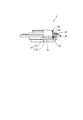
- FIG. 1 is a diagram showing a speaker structure of this embodiment.
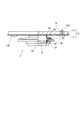
- FIG. 2 is a diagram showing the structure of the exciter.
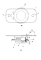
- FIG. 3 is a diagram illustrating the secondary vibration member.
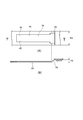
- FIG. 4 is a view showing an exciter mounting structure.
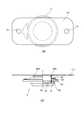
- FIG. 5 is a view showing an exciter mounting structure according to the second embodiment.
- FIG. 6 is a view showing an exciter mounting structure according to the third embodiment.
- FIG. 7 is a view showing an exciter mounting structure according to the fourth embodiment.
- FIG. 8 is a view showing an exciter mounting structure according to the fifth embodiment.
- FIG. 9 is a view showing the structure of the secondary vibration portion of the exciter mounting portion of the fifth embodiment.
- FIG. 10 is a view showing an exciter mounting structure according to the sixth embodiment.
- FIG. 11 is a view showing an exciter mounting structure according to the seventh embodiment.
- FIG. 12 shows the structure of the exciter of the eighth embodiment.
- FIG. 1A is an external view of a vehicle 2 provided with a bass reproduction apparatus 1 according to an embodiment to which the present invention is applied
- FIG. 1B is a view of the vehicle 2 shown in FIG. It is sectional drawing in -a.
- the front-rear direction of the vehicle 2 is based on the front-rear direction of the vehicle 2 shown in FIG.
- the bass reproduction apparatus 1 includes an exciter (vibration generator) 3 and a secondary vibration unit (diaphragm) 5.
- the exciter 3 is attached at an equal distance from both end points of the secondary vibration unit 5.
- the secondary vibration part 5 is arranged in a beam shape on the back side of the interior material 9 of the vehicle 2, that is, between the ceiling panel 4 that is the roof of the vehicle 2 and the interior material 9 that covers the ceiling panel 4. .
- the secondary vibration unit 5 is provided around the upper portion of the front seat over the vehicle width direction of the vehicle 2.
- the secondary vibration unit 5 is formed along the ceiling panel 4 of the vehicle 2.
- the secondary vibration portion 5 is formed in a flange shape so that both end portions 5 a hang down along the side panel of the vehicle 2.
- the secondary vibration part 5 is fastened to the vehicle frame 6 such as a side panel by screws or the like. Both ends 5 a of the secondary vibration part 5 may be configured to be fixed to the vehicle frame 6 near the window frame of the vehicle 2. According to these structures, since the secondary vibration part 5 was arrange
- the exciter 3 is used as an example of a vibration generating unit that generates a vibration corresponding to the input signal using a music signal as an input signal.
- the exciter 3 includes a pole 31, a magnet 32, a plate 33, a frame 34, a damper 35, a voice coil 38, and a bobbin 39.
- the pole 31 is formed in a concave shape and constitutes a bottom portion and a side wall portion of the exciter 3.
- the magnet 32 is a permanent magnet formed in a disk shape, and is placed on the bottom of the pole 31.
- the plate 33 is placed on the magnet 32 and is formed in a disk shape that is substantially the same as or slightly larger than the diameter of the magnet 32.
- a magnetic circuit 37 is formed in the pole 31 by a magnet 32 and a plate 33.
- a damper 35 is fixed to the frame 34, and the voice coil 38 and the bobbin 39 are elastically held by the damper 35.
- the voice coil 38 is supported and provided at one end of the bobbin 39.
- the other end of the bobbin 39 is connected to an exciter fixing portion 49 for fixing the exciter 3 to a mounting member described later.
- the exciter 3 is attached to the secondary vibration unit 5, and the secondary vibration unit 5 is connected to the vehicle frame 6.
- the secondary vibration part 5 is amplified by the vibration generated by the exciter 3.
- vibration generated by the exciter 3 is transmitted to the vehicle frame 6 through the secondary vibration unit 5 to resonate the vehicle frame 6.
- the secondary vibration unit 5 is used as a vibration transmission unit that transmits the vibration of the exciter 3 to the vehicle frame 6.
- the vehicle frame 6 becomes a part of the instrument body, that is, a resonance drum, and the sound is amplified by the vehicle frame 6 resonating. Since the exciter 3 is attached in the vicinity of an equal distance from both end points of the secondary vibration part 5, it is advantageous for the amplitude of the secondary vibration part 5.
- the secondary vibration part 5 is formed from a cold-rolled steel plate.
- 3A is a perspective view of the secondary vibration unit 5
- FIG. 3B is an enlarged view of a cross section of the secondary vibration unit 5 taken along line bb in FIG. 3A.
- the secondary vibration unit 5 is formed in a thin strip shape, and a bead 7 extending in the longitudinal direction is provided at a substantially center.
- An end portion 5a of the secondary vibration portion 5 is formed in a flange shape, and an attachment hole 8 is provided in the end portion 5a.
- the secondary vibration part 5 is fastened to the vehicle frame 6 with screws through the attachment holes 8. Further, both ends 5 b in the short direction of the secondary vibration part 5 are bent at substantially right angles in the same direction as the beads 7 for reinforcement.
- the secondary vibration part 5 is amplified by the vibration of the exciter 3, the secondary vibration part 5 is provided with the bead 7, so that the secondary vibration part 5 is prevented from generating several bellies and nodes. Thereby, the vibration of the exciter 3 can be sufficiently transmitted to the vehicle frame 6. Moreover, the secondary vibration part 5 is formed in thin plate shape. Thereby, the vibration according to the low frequency range component generated by the exciter 3 can be received and amplified by itself, and thus the vibration of the exciter 3 can be transmitted to the vehicle frame 6. As described above, the secondary vibration unit 5 gives the vehicle frame 6 the intensity that can be amplified by the vibration corresponding to the low frequency range component generated by the exciter 3 and the vibration corresponding to the low frequency range component generated by the exciter 3. It is formed in a shape that can be transmitted sufficiently. Thereby, the vibration of the exciter 3 can be transmitted to the vehicle frame 6 through the secondary vibration unit 5 to be resonated, and a rich heavy bass can be reproduced.
- the secondary vibration part 5 is formed from the cold rolled steel plate generally used with the vehicle panel, and is provided over the vehicle width direction of a vehicle. Thereby, the secondary vibration part 5 also has an effect of increasing the rigidity of the roof of the vehicle 2.
- the roof reinforcing bar may be used as the secondary vibration unit 5.
- the secondary vibration portion 5 may be configured to be fixed to the vehicle frame 6 by welding.
- the secondary vibration unit 5 has a configuration in which portions other than both end portions 5a fixed to the vehicle frame 6 are not fixed. Alternatively, a configuration may be adopted in which portions other than both end portions 5a are held so that the vibration of the secondary vibrating portion 5 is not strongly suppressed, and this holding structure may be provided on the vehicle 2 side.
- the exciter 3 that generates vibration according to the range component of the input audio signal is a secondary vibration unit provided across the vehicle width direction of the vehicle 2 around the upper portion of the front seat. 5 is provided at an equal distance from both ends 5a. That is, the exciter 3 is disposed at a position close to the ears of the passengers of the vehicle 2. Accordingly, the reproduced sound can easily reach the occupant's ear without increasing the sound pressure, and the low-frequency sound reproducing device 1 can reduce power consumption.
- the bass reproduction apparatus 1 transmits the vibration generated by the exciter 3 according to the range component of the input audio signal to the vehicle frame 6 through the secondary vibration unit 5 to resonate and amplify the sound. Thereby, sufficient sound pressure can be ensured even if a small exciter 3 is used. Furthermore, since the small exciter 3 can be used, reduction of the passenger space of the vehicle 2 due to the arrangement of the exciter 3 can be suppressed.
- the exciter 3 that generates vibration according to the low frequency range component of the audio signal and the secondary vibration unit 5 that transmits the vibration of the exciter 3 to the vehicle frame 6 are provided.
- the vibration of the exciter 3 transmitted through the secondary vibration unit 5 resonates and amplifies the vehicle frame 6 to reproduce the sound of the low frequency range component.
- the secondary vibration unit 5 is provided in a beam shape between the ceiling panel 4 of the vehicle 2 and the interior material 9 provided to cover the ceiling panel 4. Both ends 5 a were fixed to the vehicle frame 6, and the exciter 3 was attached in the vicinity of an equal distance from both ends 5 a of the secondary vibration unit 5. Thereby, the exciter 3 can be attached at a position close to the ear of the passenger of the vehicle 2. Therefore, the reproduced sound reaches the occupant's ear without increasing the sound pressure, and the power consumption of the bass reproduction apparatus 1 can be reduced. In addition, the exciter 3 is attached in the vicinity of an equal distance from both end portions 5 a of the secondary vibrating portion 5. As a result, the secondary vibration unit 5 can be easily oscillated even with small vibrations, and the secondary vibration unit 5 can be oscillated even if a small exciter is used.
- the secondary vibration unit 5 is provided across the vehicle width direction of the vehicle 2. Thereby, the vibration of the exciter 3 is transmitted to the left and right vehicle frames 6 through the secondary vibration unit 5 and resonated. As a result, low-frequency sounds are reproduced equally on the left and right sides of the passenger compartment, and rich heavy bass can be reproduced.
- the secondary vibration unit 5 has a strength or a shape that can be amplified by vibration according to the low frequency range component generated by the exciter 3.
- generates it can be set as the structure which does not make the secondary vibration part 5 amplitude. Therefore, the vibration corresponding to the high frequency range component transmitted to the vehicle frame 6 via the secondary vibration unit 5 is suppressed, and the vibration corresponding to the low frequency range component is positively transmitted to the vehicle frame 6 to obtain the desired low frequency range. Sound can be played.
- FIG. 4 is a partial cross-sectional view showing the exciter 3 and the attachment member 10 for attaching the exciter 3 to the secondary vibration part 5.
- the attachment member 10 includes a bracket 11 and a cushioning material 12.
- the exciter 3 is affixed and fixed to the attachment member 10 by adhesion or the like.
- the bracket 11 and the cushioning material 12 are formed in a substantially rectangular shape, and an attachment hole 13 is provided in the vicinity of the center of both ends in the longitudinal direction.
- the exciter 3 fixed to the bracket 11 is attached by being screwed to the secondary vibration part 5 via the buffer material 12 with an attachment screw 13A inserted into the attachment hole 13.
- the buffer material 12 absorbs the vibration component between the exciter 3 and the secondary vibration unit 5 output as noise.
- the cushioning material 12 is formed of an elastic material, and can control a vibration component to be absorbed by a difference in hardness and shape.
- a rubber material that can be variously changed in hardness by changing the material or the thickness and can be easily formed into a desired shape can be suitably used.
- the vibration component between the exciter 3 and the secondary vibration unit 5 absorbed by the buffer material 12 has an amplitude due to vibration according to the mid-high range component of the audio signal input to the exciter 3 and vibration of the exciter 3. Vibrations returned from the secondary vibration part to the exciter.
- the human ear has the characteristic that sounds in the low range are harder to hear than sounds in the high range. Therefore, when the vibration corresponding to the middle and high frequency range components of the audio signal input to the exciter 3 is transmitted to the secondary vibration unit 5, the vibration corresponding to the low frequency range component is transmitted to the vehicle frame 6. The sound of the low range that should have been masked by the high range will be difficult to hear.
- the exciter 3 may have an amplitude larger than the amplitude of the exciter itself, resulting in a distorted sound quality. There is.
- the cushioning material 12 when the exciter 3 is attached to the secondary vibration part 5, the cushioning material 12 is sandwiched between the exciter 3 and the secondary vibration part 5. As a result, the vibration corresponding to the mid-high range component transmitted from the exciter 3 to the secondary vibration unit 5 is absorbed and attenuated by the buffer material 12.
- the vibration corresponding to the low frequency range component the time from the generation of the low frequency range to the convergence of the exciter 3 by the secondary vibration is caused by the vibration of the buffer material 12 itself generated when the vibration of the exciter 3 is transmitted to the buffer material 12.
- the case where the cushioning material 12 is interposed becomes longer than the case where it is directly fixed to the portion 5.
- the exciter 3 is fixed to the secondary vibration part 5 via the cushioning material 12, so that the low-frequency sound to be reproduced can be perceived as a deep, spacious, low-pitched sound.
- the recoil of the secondary vibration part 5 that is amplified by the vibration of the exciter 3 is alleviated by the buffer material 12.
- the acceleration which increases by the influence which the exciter 3 receives a reaction can be suppressed. Therefore, the exciter 3 can generate linear vibration with respect to the input audio signal.
- the effect of attaching the exciter 3 via the buffer material 12 varies depending on the material (hardness) or the shape of the buffer material 12. That is, the vibration component absorbed by the buffer material 12 can be changed by changing the material or shape of the buffer material 12 according to the situation, and the range and quality of the sound to be reproduced can be controlled. Become.
- the attachment member 10 may be configured to be attached to the secondary vibration portion 5 by a clip or the like (not shown) in addition to the attachment screw 13A. According to these configurations, the shock absorber 12 is sandwiched between the bracket 11 and the secondary vibration portion 5 and the exciter 3 is attached. Therefore, the vibration corresponding to the high frequency range component of the audio signal input to the exciter 3 is shock absorbing. 12 is absorbed and attenuated. However, since the vibration corresponding to the high frequency range component is transmitted from the mounting screw 13A to the secondary vibration unit 5, it is effective not only for the low frequency range but also for reproducing the high frequency range.
- the vibration corresponding to the high frequency range component is transmitted through the bracket 11 by attaching the bracket 11 directly to the vehicle 2 side without using the cushioning material 12. It can also be transmitted to the next vibration section 5 to reproduce a high-frequency sound. Since the vibration corresponding to the high frequency range component is transmitted by fine vibration, it is not necessary to amplify the secondary vibration unit 5 and transmit the vibration to the vehicle frame 6. For example, an exciter is applied to a high-strength panel on the vehicle side. Even if 3 is directly attached, a high-frequency sound can be reproduced.
- the panel itself is vibrated with vibrations corresponding to the high-frequency component generated by the exciter 3, and the high-frequency sound is reproduced to produce a stereo effect.
- the sound vibration can be transmitted from the inside of the A pillar panel to the entire vehicle 2 to give the sound a spread.
- the bracket 11 to which the exciter 3 is fixed is sandwiched between the bracket 11 and the secondary vibration part 5, and the cushioning material 12 is sandwiched between the bracket 11 and the secondary vibration part 5 with the mounting screw 13 ⁇ / b> A.
- the vibration according to the high frequency range component is transmitted to the secondary vibration part 5 through the mounting screw 13A. Therefore, the vibration damping effect corresponding to the high frequency range component is small.
- the cushioning material 12 is fixed by the mounting screw 13A, the movement of the cushioning material 12 is restricted. Thereby, the vibration of the buffer material 12 itself is suppressed to the vibration according to the low frequency range component.
- an attachment member 10 ⁇ / b> A of the exciter 3 that can take a degree of freedom in the thickness of the buffer material 12 is provided. Note that the structure for attaching the secondary vibration unit 5 to the vehicle 2 and the configuration of the exciter 3 are the same as those in the first embodiment, and a description thereof will be omitted.
- the attachment member 10A is composed of a cushioning material 12A and a bracket 11 each formed in a substantially circular shape. And the exciter 3 is affixed and fixed to one surface of the buffer material 12A by adhesion
- the bracket 11 is fixed to the secondary vibration part 5 with a mounting screw or clip (not shown) through the attachment hole 13, and the exciter 3 is attached to the secondary vibration part 5.
- the vibration corresponding to the high frequency range component of the audio signal input to the exciter 3 is absorbed and attenuated by the buffer material 12A.
- the cushioning material 12 ⁇ / b> A is not provided at a portion where the bracket 11 provided with the attachment hole 13 is fixed to the secondary vibration portion 5. Thereby, even if the thickness of the cushioning material 12A is increased, the cushioning material 12A is not crushed with the attachment portion. Therefore, a degree of freedom can be taken in the thickness of the buffer material 12.
- the cushioning material 12A is not fixed by a mounting screw or the like. Thus, the movement of the shock absorbing material 12A is not restricted, and the shock absorbing material 12 itself can vibrate with vibration according to the low frequency range component generated by the exciter 3. Therefore, as described above, it is possible to reproduce an extended bass.
- the attachment member 10 ⁇ / b> A of the second embodiment the exciter 3 fixed to the buffer material 12 ⁇ / b> A is attached to the secondary vibration unit 5 via the bracket 11.
- the attachment structure which can attach a shock absorbing material to the secondary vibration part 5 directly is provided. Note that the structure for attaching the secondary vibration unit 5 to the vehicle 2 and the configuration of the exciter 3 are the same as those in the first embodiment, and a description thereof will be omitted.
- the mounting member 10B is fixed to one surface of the cushioning material 12B and the cushioning material 12B by bonding or the like, and is substantially the same as the cushioning material 12B. It is comprised from the bracket 11 formed in the magnitude
- the bracket 11 is fixed to the buffer material 12B by adhesion or the like, and the exciter 3 is attached to the surface of the bracket 11 that is not fixed to the buffer material 12B. That is, the exciter 3 is fixed to the buffer material 12B via the bracket 11.
- the buffer material 12B is provided with a plurality of mounting holes 13B, and a recess 14 formed by digging up the buffer material 12B is formed around the mounting hole 13B.
- the recess 14 is formed to be substantially the same size or slightly larger than the head 16 of the mounting screw 15 to be inserted into the mounting hole 13B.
- the head 16 is It is configured to be received in the recess 14.
- the bracket 11 is provided with a hole 18 corresponding to the position where the mounting hole 13B of the cushioning material 12B is provided.
- the cushioning material 12B is attached to the secondary vibration part 5 by the mounting screw 15 inserted into the mounting hole 13B of the cushioning material 12B through the hole 18 of the bracket 11.
- the bracket 11 plays a role of preventing the shock absorbing material 12B from being bent when the exciter 3 is vibrated, so that the vibration cannot be sufficiently transmitted to the secondary vibration unit 5.
- the shock absorbing material 12B to which the exciter 3 is fixed can be directly attached to the secondary vibration unit 5, the vibration corresponding to the high frequency range component generated by the exciter 3 is absorbed by the shock absorbing material 12B. Can be attenuated.
- the vibration corresponding to the low frequency range component can be directly transmitted to the secondary vibration unit 5, and the extended low frequency range sound can be reproduced.
- the exciter 3 is inserted through the shock absorbing material 12B with the shock absorbing material 12B and the mounting screw 15 inserted through the mounting hole 13B and the hole 18 provided in the bracket 11. It was set as the structure attached to the next vibration part 5.
- FIG. in the screw fixing in which the exciter 3 is fixed with the mounting screw 15, the mounting workability is not so good.
- an attachment portion (rubber bush) for attaching the exciter 3 to the secondary vibration portion 5 is formed integrally with the cushioning material 12C. According to this structure, the workability of attaching the exciter 3 to the secondary vibration part 5 can be improved.
- the structure for attaching the secondary vibration unit 5 to the vehicle 2 and the configuration of the exciter 3 are the same as those in the first embodiment, and a description thereof will be omitted.
- the attachment member 10 ⁇ / b> C includes a cushioning material 12 ⁇ / b> C formed in a substantially rectangular shape, and a bracket 11 fixed to one surface of the cushioning material 12 ⁇ / b> C by adhesion or the like.
- Two bush portions (attachment portions) 20 are formed integrally with the cushioning material 12 on the other surface of the cushioning material 12C.
- the bush portions 20 are respectively provided near both ends in the longitudinal direction of the cushioning material 12C.
- the bush portion 20 is formed of a bush head portion 21 and a bush shaft portion 22, and the bush head portion 21 is formed in a substantially conical shape so that the neck portion 23 has a larger diameter than the tip portion 24.
- a bush insertion hole (attachment hole) 25 for press-fitting the bush portion 20 and attaching the exciter 3 to the secondary vibration portion 5 through the cushioning material 12B is formed in the secondary vibration portion 5.
- the bush shaft portion 22 of the bush portion 20 is formed to have substantially the same size as the bush insertion hole 25.
- the attachment member 10 ⁇ / b> C is held in a state where the neck portion 23 of the bush portion 20 is hooked on the secondary vibration portion 5.
- the exciter 3 is affixed to the surface opposite to the surface fixed to the buffer material 12C of the bracket 11 formed to be approximately the same size as the buffer material 12C. That is, the exciter 3 is fixed to the cushioning material 12 ⁇ / b> C via the bracket 11.
- the bracket 11 plays a role of preventing the shock absorbing material 12B from being bent when the exciter 3 is vibrated, so that the vibration cannot be sufficiently transmitted to the secondary vibration unit 5.
- the bush portion 20 is formed integrally with the cushioning material 12 ⁇ / b> C, and the bush portion 20 is press-fitted into the bush insertion hole 25 formed in the secondary vibration portion 5 so that the exciter 3 can be easily connected to the secondary vibration portion. 5 can be attached.
- operativity to the secondary vibration part 5 of the exciter 3 can be improved.
- the buffer material 12C to which the exciter 3 is fixed can be fixed to the secondary vibration unit 5 by the bush portion 20 formed integrally with the buffer material 12C.
- generates can be absorbed and attenuate
- the vibration according to the low frequency range component can be directly transmitted to the secondary vibration part 5 via the buffer material 12C and the bush part 20. Therefore, it is possible to reproduce a low-pitched sound with an extension.
- the mounting portion 20 for mounting the exciter 3 to the secondary vibration portion 5 is integrally provided on the cushioning material 12C, and the mounting portion 20 is The exciter 3 was fixed to the secondary vibration part 5 by being inserted into the mounting hole 25 formed in the secondary vibration part 5. Thereby, the exciter 3 can be easily attached to the secondary vibration part 5, and the attachment workability
- the bracket 11 when the exciter 3 vibrates, the bracket 11 is bent or deformed when the exciter 3 vibrates, and the vibration is generated by the secondary vibration portion 5.
- the bracket 11 needs to have a predetermined strength, and it is necessary to use an iron plate or a resin material having a thickness that can ensure the strength. For this reason, it is difficult to reduce the weight or thickness of the mounting members 10B and 10C of the exciter 3.
- the mounting member 11 is reduced in weight or thickness by eliminating the reinforcing bracket 11. Note that the structure for attaching the secondary vibration unit 5 to the vehicle 2 and the configuration of the exciter 3 are the same as those in the first embodiment, and a description thereof will be omitted.
- the attachment member (attachment means) 10 ⁇ / b> D includes a base portion 40 formed of a cushioning material such as an elastic rubber material, and a slide fixing portion 41.
- the base portion 40 and the slide fixing portion 41 are each formed in a substantially rectangular shape, and are integrally formed so that each side is substantially parallel.
- a slide groove 42 is formed between the base portion 40 and the slide fixing portion 41, and the attachment member 10D has a substantially I-shaped cross section as shown in FIG. 8B.
- the exciter 3 is adhered and fixed to the surface of the base portion 40 opposite to the surface on which the slide fixing portion 41 is provided by adhesion or the like.
- the exciter 3 is attached by fixing the attachment member 10D to the secondary vibration part 5 fixed to the vehicle frame 6 of the vehicle 2.
- the width W1 of the base portion 40 of the mounting member 10D is formed to be substantially the same as the width W3 of the secondary vibration portion 5.
- a cutout hole 36 is formed in the secondary vibration part 5 for slidingly inserting the attachment member 10D into the secondary vibration part 5 and fixing it.
- the cutout hole 36 includes an insertion portion 43 and a slide portion 44.
- a stopper 45 is provided near the end opposite to the end where the insertion portion 43 of the slide portion 44 is provided.
- FIG. 9B is a cross-sectional view taken along line bb in FIG.
- the secondary vibrating portion 5 is a portion where the insertion portion 43 is provided, and is bent obliquely.
- the height H2 of the bent portion is the slide fixing portion of the mounting member 10D. It is substantially the same as or slightly higher than the height H1 of 41.
- the width W4 of the slide portion 44 of the secondary vibration portion 5 is formed to be substantially the same as or slightly smaller than the width W2 of the slide groove 42 of the mounting member 10D.
- the slide fixing portion 41 of the mounting member 10D is inserted above the cutout hole 36 via the insertion portion 43 from the direction of the arrow in FIG.
- the mounting member 10 ⁇ / b> D is slid into the stopper 45 in a state where both sides of the cutout hole 36 are sandwiched between the slide grooves 42. Accordingly, as illustrated in FIG. 8C, the attachment member 10 ⁇ / b> D is attached to the secondary vibration unit 5 with the secondary vibration unit 5 sandwiched between the slide fixing unit 41 and the base unit 40.
- the secondary vibrating portion 5 serves as a reinforcing plate for the mounting member 10D formed of a cushioning material such as an elastic rubber material.
- a cushioning material such as an elastic rubber material.
- the mounting member 10E is composed of a cushioning material 12D and a bracket 11D.
- the cushioning material 12 ⁇ / b> D and the bracket 11 ⁇ / b> D are formed in a substantially disk shape having a diameter substantially the same as the diameter of the exciter 3.
- the exciter 3 is affixed to the bracket 11D and fixed to the cushioning material 12D via the bracket 11D.
- the buffer material 12D, the bracket 11D, and the exciter 3 are fixed to each other by bonding or the like.
- a bush portion (attachment means) 20D is provided at substantially the center of the disk-shaped cushioning material 12D.
- the bush portion 20D is formed of a bush head portion 21D and a bush shaft portion 22D, and the bush head portion 21D is formed in a substantially conical shape so that the neck portion 23D has a larger diameter than the tip portion 24D.
- the secondary vibration part 5 is formed with a bush insertion hole (not shown) for inserting the bush part 20 ⁇ / b> D and attaching the exciter 3 to the secondary vibration part 5 with the cushioning material 12 ⁇ / b> D interposed therebetween. When the exciter 3 is attached to the secondary vibration part 5, the bracket head 11D is held at the point X in FIG.
- the structure which slide-inserts into a hole may be sufficient.
- the surface of the cushioning material 12D opposite to the surface on which the bush portion 20D is provided is provided with a convex portion 46 that fits on the inner periphery of the exciter 3.
- the protrusion 46 may be provided by being inserted into the exciter 3.
- the bracket 11D is provided with a hole through which the convex portion 46 passes.
- the convex portion 46 is configured such that when the pole 31 is pushed, the cushioning material 12D first hits the plate 33 inside the exciter 3 before the pole 31 hits the voice coil 38 provided inside the exciter 3. ing.
- the attachment member 10F is comprised from the shock absorbing material 12E and the bracket 11E.
- the cushioning material 12E and the bracket 11E are each formed in a substantially rectangular shape having substantially the same dimensions, and mounting holes 47 are provided in the vicinity of the center on both ends in the longitudinal direction.
- the exciter 3 is affixed and fixed to the approximate center of the bracket 11E by adhesion or the like.
- the dowel (mounting convex portion) 48 is formed in the secondary vibrating portion 5 at a position corresponding to the mounting hole 47 of the mounting member 10F according to the mounting position of the exciter 3. ing.
- the dowel 48 may be formed integrally with the secondary vibration unit 5.
- the dowel 48 protrudes in a convex shape on the surface of the secondary vibrating portion 5 on the side where the exciter 3 is attached.
- a mounting hole 47 into which the dowel 48 is press-fitted is formed at a position corresponding to the dowel 48.
- the exciter 3 is attached to the secondary vibration part 5 by inserting (press-fitting) a dowel 48 into the attachment hole 47 of the attachment member 10F with the cushioning material 12E sandwiched between the bracket 11E and the secondary vibration part 5. It is done.
- the vibration corresponding to the high frequency range component generated by the exciter 3 is attenuated by the buffer material 12E, and the vibration corresponding to the low frequency range component generated by the exciter 3 is directly reduced to 2 through the buffer material 12E.
- the sound can be transmitted to the next vibration unit 5 and an extended low-frequency sound can be reproduced.
- it is possible to adjust various sound qualities by freely changing the material (hardness) and shape of the buffer material 12E.
- ⁇ Eighth Embodiment> By the way, when the exciter 3 generates a vibration corresponding to the input sound range component, the voice coil 38 generates heat. If the heat generated from the voice coil 38 is not dissipated and reaches the exciter 3, the coating of the voice coil 38 may be melted by the heat, resulting in a short circuit.
- a bass reproduction apparatus 1 having a heat dissipation structure that efficiently dissipates heat generated from the voice coil 38. Note that the structure for attaching the secondary vibration unit 5 to the vehicle 2 and the configuration of the exciter 3 are the same as those in the first embodiment, and a description thereof will be omitted.
- FIG. 12 is a view showing the exciter 3 and the bracket 11F of the eighth embodiment.
- the bobbin 39A, the exciter fixing portion 49A, and the bracket 11F are formed from a material having excellent heat dissipation characteristics, such as an aluminum alloy.
- the bracket 11F is formed in a size having a heat radiation area that can sufficiently radiate the heat generated by the voice coil 38. According to this configuration, the heat generated by the voice coil 38 can be transferred to the bobbin 39A, the exciter fixing part (fixing part) 49A, and the bracket 11F, and efficiently dissipated from the bracket 11F.
- the exciter fixing portion 49A is formed in a plate shape having the same size as the bracket 11F, the bracket 11F is omitted, and the exciter 3 is used as the secondary vibration portion by using the exciter fixing portion 49A. It is good also as a structure attached to 5. According to this configuration, the bracket 11F can be omitted and the number of parts can be reduced.
Landscapes
- Engineering & Computer Science (AREA)
- Physics & Mathematics (AREA)
- Acoustics & Sound (AREA)
- Signal Processing (AREA)
- Health & Medical Sciences (AREA)
- Otolaryngology (AREA)
- Mechanical Engineering (AREA)
- Fittings On The Vehicle Exterior For Carrying Loads, And Devices For Holding Or Mounting Articles (AREA)
- Diaphragms For Electromechanical Transducers (AREA)
- Details Of Audible-Bandwidth Transducers (AREA)
Abstract
エキサイターを用いて、乗員スペースを狭めることなく豊かな重低音を再生することができる低音再生装置、及び、低音再生方法を提供する。 音声信号の音域成分に応じた振動を生成する振動発生部3と、振動発生部3の振動を車両フレーム6に伝える2次振動部5と、を備え、2次振動部5を通じて伝えられた振動発生部3の振動で車両フレーム6を共鳴させて低音域成分の音を再生することを特徴とする。
Description
本発明は、エキサイターを使用した車両用の低音再生装置、及び、低音再生方法に関する。
従来、音場再生において低音域の音の再生を担うウーハーは、大きくて重い振動板と、振動板を動かす磁気回路とをスピーカーボックス内に取り付けて構成されている。車両内で低音域の音を再生するために、ウーハーを搭載する場合には、ウーハーは構造的に重量が重いため、車両の燃費にとって不利となる、また、ウーハーを駆動するために車両のバッテリーに負荷がかかる、さらには、車両のような限られたスペースでは必要なスピーカーボックスの容積を十分得るのはレイアウト的に難しい、等という問題があった。
一方、エキサイターを車両の内装材に取り付け、この内装材をエキサイターにより振動させることで音を再生する技術が提供されている(例えば、特許文献1参照)。
一方、エキサイターを車両の内装材に取り付け、この内装材をエキサイターにより振動させることで音を再生する技術が提供されている(例えば、特許文献1参照)。
しかしながら、内装材を振動させてウーハーと同等の低音域を発生させるためには、低音域の周波数で内装材を振動させ、且つ、十分な音圧を確保するために振幅を大きくする必要がある。低音域の周波数で内装材を大きく振幅させるためには、重量の重いエキサイターを使用すれば有利となるが、結果としてエキサイター自体が大きくなってしまうため重量、及び、乗員スペースの面で不利となってしまう。また、内装材を大きく振動させることで内装材に装着されている部品自体の鳴きや車両板金パネルとの干渉部が振動を受けることによって異音を発生させる可能性があるという問題がある。
本発明は、上述した従来の技術が有する課題を解消し、エキサイターを用いて、乗員スペースを狭めることなく重低音を再生することができる低音再生装置、及び、低音再生方法を提供することを目的とする。
本発明は、上述した従来の技術が有する課題を解消し、エキサイターを用いて、乗員スペースを狭めることなく重低音を再生することができる低音再生装置、及び、低音再生方法を提供することを目的とする。
上記目的を達成するために、本発明は、音声信号の音域成分に応じた振動を生成する振動発生部と、前記振動発生部の振動を車両フレームに伝える2次振動部と、を備え、前記2次振動部を通じて伝えられた前記振動発生部の振動で前記車両フレームを共鳴させて低音域成分の音を再生することを特徴とする。
また、本発明は、上記の低音再生装置において、前記2次振動部を、前記振動発生部が生成する低音域成分に応じた振動で振幅可能な強度、或いは、形状とし、前記2次振動部と、前記振動発生部と、の間に弾性材から形成され、ノイズとして出力される前記振動発生部と前記2次振動部の間の振動成分を吸収する緩衝材を設けたことを特徴とする。
また、本発明は、上記の低音再生装置において、前記2次振動部を、車両の天井パネルに沿って、前記天井パネルとこの天井パネルをおおって設けられる内装材との間に車両の車幅方向に亘る梁状に設け、この2次振動部の両端を車両フレームに固定して、前記2次振動部の両端からの等距離付近に前記振動発生部を取り付けたことを特徴とする。
また、本発明は、上記の低音再生装置において、前記振動発生部は、底部と側壁部とを構成するポールと、当該ポールの底部に載置される永久磁石と、当該磁石の上に載置されるプレートと、ダンパーにより、ボイスコイル、及び、ボビンを弾性的に保持するフレームとを有することを特徴とする。
また、本発明は、上記の低音再生装置において、前記振動発生部を前記2次振動部に取り付ける取付部材を備え、当該取付部材に前記緩衝材を設け、前記振動発生部と前記緩衝材とを前記2次振動部に一体に取り付け可能としたことを特徴とする。
また、本発明は、上記の低音再生装置において、前記緩衝材に、前記振動発生部を前記2次振動部に取り付けるための取付部を一体に設け、前記取付部を前記2次振動部に形成された取付孔に圧入して、前記振動発生部を前記2次振動部に固定したことを特徴とする。
また、本発明は、上記の低音再生装置において、前記緩衝材は、前記2次振動部に形成された切抜孔に係合する溝部を有する断面略I字型に形成され、前記溝部の上下の部位で前記2次振動部を挟み込んだことを特徴とする。
また、本発明は、上記の低音再生装置において、前記緩衝材は、前記ポール内部に挿入され前記側壁部の内周に嵌合する凸部を備え、前記凸部は、前記ポールが外側から押された際に、前記ポールが前記ボイスコイルに当たるより前に前記プレートに当たるように設けられていることを特徴とする。
また、本発明は、上記の低音再生装置において、前記2次振動部に、前記振動発生部の取付方向に突出する取付凸部を設け、前記取付部材に、前記取付凸部が圧入される取付孔を設けたことを特徴とする。
また、本発明は、上記の低音再生装置において、前記取付部材は、前記緩衝材と、当該緩衝材が一方の面に取り付けられ、他方の面に前記振動発生部が取り付けられるブラケットと、を有し、前記ブラケット、前記振動発生部を前記ブラケットに固定する固定部、及び、前記固定部に連結され前記ボイスコイルを支持するボビン、を優れた放熱特性を有する材料から形成したことを特徴とする。
また、上記目的を達成するために、本発明は、音声信号の音域成分に応じた振動を生成する振動発生手段と、前記振動発生手段が生成した振動を車両フレームに伝える振動伝達手段と、を備え、前記振動伝達手段を通じて伝えられた前記振動発生手段の振動で前記車両フレームを共鳴させて低音域成分の音を再生することを特徴とする。
本発明によれば、音声信号の音域成分に応じた振動を生成する振動発生部と、前記振動発生部の振動を車両フレームに伝える2次振動部と、を備え、前記2次振動部を通じて伝えられた前記振動発生部の振動で前記車両フレームを共鳴させて低音域成分の音を再生するため、小型の振動発生部を用いても十分な音圧を確保することができ、乗員スペースを狭めることなく振動発生部を使用して重低音を再生することができるという効果を奏する。
<第1実施形態>
以下、図面を参照して本発明の実施形態について説明する。
図1(A)は本発明を適用した実施形態に係る低音再生装置1を備えた車両2の外観視図であり、図1(B)は、図1(A)に示した車両2のa―aでの断面図である。なお、車両2の前後方向は、図1(A)に示した車両2の前後に基づくものであり、この前後に対する左右を車両2の車幅方向とする。
図1(B)に示すように、低音再生装置1は、エキサイター(振動発生部)3と、2次振動部(振動板)5とから構成される。エキサイター3は、2次振動部5の両端点からの等距離付近に取り付けられている。
以下、図面を参照して本発明の実施形態について説明する。
図1(A)は本発明を適用した実施形態に係る低音再生装置1を備えた車両2の外観視図であり、図1(B)は、図1(A)に示した車両2のa―aでの断面図である。なお、車両2の前後方向は、図1(A)に示した車両2の前後に基づくものであり、この前後に対する左右を車両2の車幅方向とする。
図1(B)に示すように、低音再生装置1は、エキサイター(振動発生部)3と、2次振動部(振動板)5とから構成される。エキサイター3は、2次振動部5の両端点からの等距離付近に取り付けられている。
2次振動部5は、車両2の内装材9の裏側、つまり、車両2の屋根である天井パネル4と天井パネル4をおおって設けられる内装材9との間に梁状に配設される。また、2次振動部5は、車両2の車幅方向に亘って、前部座席の上部辺りに設けられる。2次振動部5は、車両2の天井パネル4に沿って形成される。また、2次振動部5は、その両端部5aが、車両2のサイドパネルに沿って垂れ下がるようにフランジ状に形成されている。2次振動部5は、サイドパネル等の車両フレーム6にビス等によって締結される。2次振動部5の両端部5aは、車両2の窓枠上近くで車両フレーム6に固定されている構成であっても良い。
これらの構成によれば、2次振動部5を天井パネル4に沿って、天井パネル4の近くに配設したため、車両2の車室内の頭上スペースを狭めることなく2次振動部5にエキサイター3を取り付けることができる。
これらの構成によれば、2次振動部5を天井パネル4に沿って、天井パネル4の近くに配設したため、車両2の車室内の頭上スペースを狭めることなく2次振動部5にエキサイター3を取り付けることができる。
エキサイター3は、音楽信号を入力信号として、この入力信号に応じた振動を生成する振動発生手段の一例として用いられる。エキサイター3は、図2に示すように、ポール31、マグネット32、プレート33、フレーム34、ダンパー35、ボイスコイル38、ボビン39から概略構成される。ポール31は、凹状に形成され、エキサイター3の底部と側壁部とを構成する。マグネット32は、円盤形状に形成された永久磁石であり、ポール31の底部に載置されている。プレート33は、マグネット32の上に載置され、マグネット32の直径とほぼ同じか、僅かに大きい円盤状に形成されている。
エキサイター3は、ポール31内に、マグネット32と、プレート33とによって磁気回路37が形成される。また、フレーム34には、ダンパー35が固定され、ダンパー35により、ボイスコイル38、及び、ボビン39が弾性的に保持されている。ボイスコイル38は、ボビン39の一端部に支持されて備えられる。ボビン39の他端部は、エキサイター3を後述する取付部材に固定するためのエキサイター固定部49に連結されている。
エキサイター3に音声信号が入力されると、ポール31内に、マグネット32とプレート33とによって形成された磁気回路37と、ダンパー35によって保持されたボイスコイル38、及び、ボビン39とが相互に作用し、入力された音域成分に応じた振動が生成される。
エキサイター3に音声信号が入力されると、ポール31内に、マグネット32とプレート33とによって形成された磁気回路37と、ダンパー35によって保持されたボイスコイル38、及び、ボビン39とが相互に作用し、入力された音域成分に応じた振動が生成される。
エキサイター3は、図1に示したように、2次振動部5に取り付けられ、2次振動部5は、車両フレーム6に接続されている。これにより、エキサイター3が生成した振動によって2次振動部5は振幅する。そして、この振幅によって、エキサイター3が生成した振動が、2次振動部5を通じて、車両フレーム6伝えられ車両フレーム6を共鳴させる。つまり、2次振動部5は、エキサイター3の振動を車両フレーム6に伝える振動伝達手段として用いられる。例えば、2次振動部5を弦楽器の弦の部分と見立てると、車両フレーム6が楽器本体の部分、つまり共鳴胴となり、車両フレーム6が共鳴することによって音が増幅される。エキサイター3は、2次振動部5の両端点からの等距離付近に取り付けられているため、2次振動部5を振幅させるのに有利となる。
2次振動部5は、冷間圧延鋼板から形成される。図3(A)は2次振動部5の斜視図であり、図3(B)は、2次振動部5を図3(A)中のb―bで切断した断面の拡大図である。2次振動部5は、図3に示したように、薄板の帯状に形成され、長手方向に亘るビード7が略中央に設けられている。2次振動部5の端部5aは、フランジ状に形成され、端部5aには取付孔8が設けられている。2次振動部5は、この取付孔8を介して車両フレーム6にビスにて締結される。また、2次振動部5の短手方向の両端5bは、補強のために、ビード7と同じ方向に向かって略直角に折り曲げられている。
2次振動部5は、エキサイター3の振動によって振幅するが、ビード7を備えるため、2次振動部5にいくつかの腹と節が発生するのが防がれる。これにより、エキサイター3の振動を車両フレーム6に十分に伝えることができる。
また、2次振動部5は、薄板状に形成されている。これにより、エキサイター3が生成した低音域成分に応じた振動を受けて自身で振幅することができ、よって、エキサイター3の振動を車両フレーム6に伝えることができる。このように、2次振動部5は、エキサイター3が生成した低音域成分に応じた振動で振幅することができる強度、及び、エキサイター3が生成した低音域成分に応じた振動を車両フレーム6に十分に伝えることができる形状に形成されている。これにより、エキサイター3の振動を2次振動部5を通じて車両フレーム6に伝えて共鳴させ、豊かな重低音を再生することができる。
また、2次振動部5は、薄板状に形成されている。これにより、エキサイター3が生成した低音域成分に応じた振動を受けて自身で振幅することができ、よって、エキサイター3の振動を車両フレーム6に伝えることができる。このように、2次振動部5は、エキサイター3が生成した低音域成分に応じた振動で振幅することができる強度、及び、エキサイター3が生成した低音域成分に応じた振動を車両フレーム6に十分に伝えることができる形状に形成されている。これにより、エキサイター3の振動を2次振動部5を通じて車両フレーム6に伝えて共鳴させ、豊かな重低音を再生することができる。
また、2次振動部5は、車両パネルで一般的に使用されている冷間圧延鋼板から形成され、車両の車幅方向に亘って設けられる。これにより、2次振動部5は、車両2の屋根の剛性を高める効果もある。車両2が、車幅方向に亘って、車両フレーム6間で架設された屋根補強用バーを備える場合には、この屋根補強用バーを2次振動部5として用いる構成としても良い。車両2の屋根補強用バーを2次振動部5として用いる場合には、2次振動部5は、車両フレーム6に溶接固定される構成であっても良い。
また、2次振動部5は、車両フレーム6に固定された両端部5a以外の部分は、固定しない構成とすることが望ましい。或いは、2次振動部5の振動が強く抑制を受けないように、両端部5a以外の部分が保持される構成であっても良く、この保持構造を車両2側に設ける構成としても良い。
また、2次振動部5は、車両フレーム6に固定された両端部5a以外の部分は、固定しない構成とすることが望ましい。或いは、2次振動部5の振動が強く抑制を受けないように、両端部5a以外の部分が保持される構成であっても良く、この保持構造を車両2側に設ける構成としても良い。
これらの構成によれば、入力された音声信号の音域成分に応じた振動を生成するエキサイター3は、前部座席の上部辺りで、車両2の車幅方向に亘って設けられた2次振動部5の両端部5aからの等距離付近に設けられる。つまり、エキサイター3は、車両2の乗員の耳元に近い位置に配設される。これにより、音圧を大きくしなくても、再生した音が乗員の耳に届き易くなり、低音再生装置1として電力の低消費が可能となる。
また、低音再生装置1は、入力された音声信号の音域成分に応じてエキサイター3が生成した振動を、2次振動部5を通じて車両フレーム6に伝え共鳴さて音を増幅し再生する。これにより、小型のエキサイター3を用いても十分な音圧を確保することができる。さらに、小型のエキサイター3を使用できることで、エキサイター3の配設による車両2の乗員スペースの縮小を抑えることができる。
以上説明したように、本実施形態によれば、音声信号の低音域成分に応じた振動を生成するエキサイター3と、エキサイター3の振動を車両フレーム6に伝える2次振動部5と、を備え、2次振動部5を通じて伝えられたエキサイター3の振動で車両フレーム6を共鳴させて増幅し、低音域成分の音を再生する。これにより、小型のエキサイター3を用いても十分な音圧を確保することができ、乗員スペースを狭めることなくエキサイター3を利用して豊かな重低音を再生することができる。
また、本実施形態によれば、2次振動部5を車両2の天井パネル4とこの天井パネル4をおおって設けられる内装材9との間に梁状に設け、この2次振動部5の両端部5aを車両フレーム6に固定して、2次振動部5の両端5部aからの等距離付近にエキサイター3を取り付けた。これにより、車両2の乗員の耳元に近い位置にエキサイター3を取り付けることができる。そのため、音圧を大きくしなくても、再生した音が乗員の耳に届き、低音再生装置1の消費電力の低減を図ることが可能となる。また、エキサイター3は、2次振動部5の両端部5aからの等距離付近に取り付けられている。これにより、小さな振動でも簡単に2次振動部5を振幅させることができ、小型のエキサイターを用いても2次振動部5を振幅させることができる。
また、本実施形態によれば、2次振動部5は、車両2の車幅方向に亘って設けられている。これにより、エキサイター3の振動は、2次振動部5を通じて、左右の車両フレーム6に伝えられて共鳴される。そのため、低音域の音が車室内の左右で均等に再生され、豊かな重低音を再生することが可能となる。
また、本実施形態によれば、2次振動部5を、エキサイター3が生成する低音域成分に応じた振動で振幅可能な強度、或いは、形状とした。これにより、エキサイター3が生成する高音域成分に応じた微細振動では、2次振動部5を振幅させない構成とすることができる。よって、2次振動部5を介して車両フレーム6に伝わる高音域成分に応じた振動を抑制し、かつ、低音域成分に応じた振動を積極的に車両フレーム6に伝えて、所望する低音域の音を再生することができる。
次に、2次振動部5へのエキサイター3の取付構造について説明する。
図4はエキサイター3と、エキサイター3を2次振動部5に取り付けるための取付部材10とを示した部分断面図である。取付部材10は、ブラケット11と、緩衝材12と、から構成される。エキサイター3は、取付部材10に接着等によって貼り付けられて固定される。ブラケット11、及び、緩衝材12は、略矩形に形成され、長手方向の両端側中央付近には、取付孔13が設けられている。ブラケット11に固定されたエキサイター3は、この取付孔13に挿入される取付ビス13Aで、2次振動部5に緩衝材12を介して螺合されて取付られる。
図4はエキサイター3と、エキサイター3を2次振動部5に取り付けるための取付部材10とを示した部分断面図である。取付部材10は、ブラケット11と、緩衝材12と、から構成される。エキサイター3は、取付部材10に接着等によって貼り付けられて固定される。ブラケット11、及び、緩衝材12は、略矩形に形成され、長手方向の両端側中央付近には、取付孔13が設けられている。ブラケット11に固定されたエキサイター3は、この取付孔13に挿入される取付ビス13Aで、2次振動部5に緩衝材12を介して螺合されて取付られる。
緩衝材12は、ノイズとして出力されるエキサイター3と2次振動部5の間の振動成分を吸収する。緩衝材12は、弾力性のある素材から形成され、硬度、及び、形状の違いにより吸収する振動成分をコントロールすることができる。緩衝材12の材質としては、材料或いは厚さを変えることで硬度を多様に変えることができるとともに、所望する形状に容易に形成することができるゴム材を好適に用いることができる。
ところで、緩衝材12で吸収されるエキサイター3と2次振動部5の間の振動成分には、エキサイター3に入力された音声信号の中高音域成分に応じた振動と、エキサイター3の振動によって振幅した2次振動部からエキサイターに戻される振動とが含まれる。人間の耳は低音域の音は、高音域の音よりも聞き取りにくいという特性がある。そのため、エキサイター3に入力された音声信号の中高音域成分に応じた振動が2次振動部5に伝えられた場合、低音域成分に応じた振動が車両フレーム6に伝わることで発生しているはずの低音域の音が高音域の音にマスキングされて聞き取りにくくなってしまう。また、エキサイター3の振動によって振幅した2次振動部の反動がエキサイターに戻された場合には、エキサイター3は、自身が振幅できる以上に振幅してしまい、歪感の多い音質となってしまう場合がある。
本発明の実施形態では、エキサイター3は、2次振動部5に取り付けるにあたり、緩衝材12をエキサイター3と2次振動部5の間に挟み込んで取り付けられる。これにより、エキサイター3から2次振動部5に伝えられる中高音域の成分に応じた振動は、緩衝材12で吸収され、減衰される。また、低音域成分に応じた振動に関しては、エキサイター3の振動が緩衝材12に伝わった際に生じる緩衝材12自身の振動により、低音域の発生から収束までの時間がエキサイター3を2次振動部5に直接固定した場合に対し、緩衝材12を介した場合の方が長くなる。これによって、緩衝材12を介してエキサイター3を2次振動部5に固定したことで、再生される低音域の音が奥行きのある、ゆったりとした伸びのある低音として感じられるようになる。
またエキサイター3が振動したことで振幅する2次振動部5の反動は、緩衝材12で緩和される。これにより、エキサイター3が反動を受ける影響で増加してしまう加速度を抑えることができる。よって、エキサイター3は、入力される音声信号に対しリニアな振動を生成することが可能となる。
緩衝材12を介してエキサイター3を取り付ける効果は、緩衝材12の材質(硬度)、または、形状の違いにより変動する。つまり、状況に応じて緩衝材12の材質、或いは、形状を変化させることで緩衝材12で吸収する振動成分を変えることができ、再生する音の音域、及び、音質をコントロールすることが可能となる。
取付部材10は、取付ビス13Aの他に、不図示のクリップ等で2次振動部5に取り付けられる構成としても良い。
これらの構成によれば、ブラケット11と2次振動部5の間に緩衝材12を挟み込んでエキサイター3を取り付けたため、エキサイター3に入力された音声信号の高音域の成分に応じた振動が緩衝材12で吸収されて減衰する。しかしながら、取付ビス13Aから高音域成分に応じた振動が2次振動部5へ伝わるため、低音域の音だけではなく、高音域の音を再生させたい場合にも有効的である。
これらの構成によれば、ブラケット11と2次振動部5の間に緩衝材12を挟み込んでエキサイター3を取り付けたため、エキサイター3に入力された音声信号の高音域の成分に応じた振動が緩衝材12で吸収されて減衰する。しかしながら、取付ビス13Aから高音域成分に応じた振動が2次振動部5へ伝わるため、低音域の音だけではなく、高音域の音を再生させたい場合にも有効的である。
また、高音域の音を積極的に再生させたい場合には、緩衝材12を介さずに、ブラケット11を直接車両2側に取り付けることで高音域成分に応じた振動をブラケット11を介して2次振動部5に伝えて、高音域の音を再生することもできる。高音域成分に応じた振動は、微細振動での伝達となるため、2次振動部5を振幅させて、振動を車両フレーム6に伝える必要がなく、例えば、車両側の高強度のパネルにエキサイター3を直接取り付けても高音域の音を再生することができる。例えば、車両2の左右のAピラーパネルの内側に直接エキサイターを取り付けることで、エキサイター3が発生する高音域成分に応じた振動でパネルそのものを振動させて高音域の音を再生させて、ステレオ感を持たせることができるとともに、Aピラーパネルの内側から車両2の全体に音振動を伝えて、音に広がりを持たせることもできる。
<第2実施形態>
第1実施形態の取付部材10では、エキサイター3が固定されたブラケット11を、ブラケット11と2次振動部5の間に緩衝材12を挟み込んで、取付ビス13Aでブラケット11を2次振動部5に螺合して取付ける構成とした。この構成によれば、取付ビス13Aを介して、高音域成分に応じた振動が2次振動部5に伝わる。そのため、高音域成分に応じた振動の減衰効果が少ない。また、取付ビス13Aで緩衝材12が固定されることで、緩衝材12の動きに規制がかかる。これにより、低音域成分に応じた振動に緩衝材12自身の振動が抑制される。よって、緩衝材12を使用した事による低音域の音の伸びが感じられなくなる。また、緩衝材12の厚みを厚くすると、2次振動部5への取り付け部付近の緩衝材12がつぶれてブラケット11が変形してしまうおそれがある。これにより、緩衝材12の厚さに対する自由度がない。
この第二実施形態では、緩衝材12の厚さに自由度が取れるエキサイター3の取付部材10Aを提供する。なお、2次振動部5の車両2への取付構造、及び、エキサイター3の構成については、第1実施形態と同一であり、その説明を省略する。
第1実施形態の取付部材10では、エキサイター3が固定されたブラケット11を、ブラケット11と2次振動部5の間に緩衝材12を挟み込んで、取付ビス13Aでブラケット11を2次振動部5に螺合して取付ける構成とした。この構成によれば、取付ビス13Aを介して、高音域成分に応じた振動が2次振動部5に伝わる。そのため、高音域成分に応じた振動の減衰効果が少ない。また、取付ビス13Aで緩衝材12が固定されることで、緩衝材12の動きに規制がかかる。これにより、低音域成分に応じた振動に緩衝材12自身の振動が抑制される。よって、緩衝材12を使用した事による低音域の音の伸びが感じられなくなる。また、緩衝材12の厚みを厚くすると、2次振動部5への取り付け部付近の緩衝材12がつぶれてブラケット11が変形してしまうおそれがある。これにより、緩衝材12の厚さに対する自由度がない。
この第二実施形態では、緩衝材12の厚さに自由度が取れるエキサイター3の取付部材10Aを提供する。なお、2次振動部5の車両2への取付構造、及び、エキサイター3の構成については、第1実施形態と同一であり、その説明を省略する。
この第2実施形態では、図5(A)に示すように、取付部材10Aは、それぞれ略円形に形成された緩衝材12Aと、ブラケット11とから構成されている。そして、エキサイター3は、緩衝材12Aの一方の面に接着などによって貼り付けられて固定される。図5(B)に示すように緩衝材12Aの、エキサイター3が貼り付けられている一方の面とは逆の他方の面は、接着などによってブラケット11に固定されている。ブラケット11には、複数の取付孔13が設けられる。取付孔13は、ブラケット11の緩衝材12Aが固定されている領域の外側に設けられる。取付孔13を介して不図示の取付ビス或いはクリップ等でブラケット11を、2次振動部5に固定して、エキサイター3を、2次振動部5に取り付ける。エキサイター3に入力された音声信号の高音域成分に応じた振動は、緩衝材12Aで吸収されて減衰する。また、取付孔13が設けられたブラケット11の2次振動部5への固定部分には緩衝材12Aが設けられていない。これにより、緩衝材12Aの厚さを厚くしても、取り付け部付で緩衝材12Aがつぶれることがない。よって、緩衝材12の厚さに自由度がとれる。また、緩衝材12Aは、取付ビス等によって固定されない。これにより、緩衝材12Aの動きに規制がかからず、エキサイター3が生成する低音域成分に応じた振動で緩衝材12自身が振動することができ。よって、上述したように、伸びのある低音を再生することが可能となる。
<第3実施形態>
第2実施形態の取付部材10Aでは、緩衝材12Aに固定されたエキサイター3をブラケット11を介して2次振動部5に取り付けている。これにより、緩衝材12Aのみを介して2次振動部5にエキサイター3を取り付けた場合と比較すると、低音域の2次振動部5への伝わりが間接的となってしまう。
この第3実施形態では、緩衝材を直接的に2次振動部5に取り付けることができる取付構造を提供する。なお、2次振動部5の車両2への取付構造、及び、エキサイター3の構成については、第1実施形態と同一であり、その説明を省略する。
第2実施形態の取付部材10Aでは、緩衝材12Aに固定されたエキサイター3をブラケット11を介して2次振動部5に取り付けている。これにより、緩衝材12Aのみを介して2次振動部5にエキサイター3を取り付けた場合と比較すると、低音域の2次振動部5への伝わりが間接的となってしまう。
この第3実施形態では、緩衝材を直接的に2次振動部5に取り付けることができる取付構造を提供する。なお、2次振動部5の車両2への取付構造、及び、エキサイター3の構成については、第1実施形態と同一であり、その説明を省略する。
図6(A),(B)に示すように、取付部材10Bは、略矩形に形成された緩衝材12Bと、緩衝材12Bの一方の面に接着等によって固定され、緩衝材12Bと略同じ大きさに形成されたブラケット11とから構成されている。緩衝材12Bには、ブラケット11が接着等によって固定され、ブラケット11の緩衝材12Bに固定されていない方の面には、エキサイター3が貼り付けられている。つまり、緩衝材12Bに、ブラケット11を介して、エキサイター3が固定されている。緩衝材12Bには、複数の取付孔13Bが設けられるとともに、取付孔13Bの周囲には、緩衝材12Bを掘り上げた凹部14が形成されている。凹部14は、取付孔13Bに挿入する取付ビス15の頭部16と略同じ大きさ、或いは若干大きく形成され、取付孔13Bに取付ビス15の軸部17を挿入した際に、頭部16が凹部14に収容されるように構成されている。
ブラケット11には、緩衝材12Bの取付孔13Bが設けられている位置に対応して、孔18が設けられる。緩衝材12Bは、ブラケット11の孔18を介して緩衝材12Bの取付孔13Bに挿入した取付ビス15によって2次振動部5に取り付けられる。ブラケット11は、エキサイター3が振動した際に緩衝材12Bが湾曲して振動を2次振動部5へ十分に伝えることができなくなってしまうのを防止する役割を果たす。
これらの構成によれば、エキサイター3が固定された緩衝材12Bを直接的に2次振動部5へ取り付けることができるため、エキサイター3が生成する高音域成分に応じた振動を緩衝材12Bで吸収して減衰させることができる。更に、低音域成分に応じた振動を直接的に2次振動部5へ伝えることができ、伸びのある低音域の音を再生することができる。
これらの構成によれば、エキサイター3が固定された緩衝材12Bを直接的に2次振動部5へ取り付けることができるため、エキサイター3が生成する高音域成分に応じた振動を緩衝材12Bで吸収して減衰させることができる。更に、低音域成分に応じた振動を直接的に2次振動部5へ伝えることができ、伸びのある低音域の音を再生することができる。
<第4実施形態>
第3実施形態の取付部材10Bでは、緩衝材12B、及び、ブラケット11に設けられた取付孔13B、及び、孔18を介して挿入した取付ビス15で、緩衝材12Bを介してエキサイター3を2次振動部5に取り付ける構成とした。しかしながら、取付ビス15でエキサイター3を固定するビス固定では、取り付け作業性があまり良くない。
この第4実施形態では、取付作業性を考慮して、緩衝材12Cに、エキサイター3を2次振動部5に取り付ける取付部(ゴムブッシュ)を一体に形成している。この構成によれば、エキサイター3の2次振動部5への取付作業性を向上させることができる。なお、2次振動部5の車両2への取付構造、及び、エキサイター3の構成については、第1実施形態と同一であり、その説明を省略する。
第3実施形態の取付部材10Bでは、緩衝材12B、及び、ブラケット11に設けられた取付孔13B、及び、孔18を介して挿入した取付ビス15で、緩衝材12Bを介してエキサイター3を2次振動部5に取り付ける構成とした。しかしながら、取付ビス15でエキサイター3を固定するビス固定では、取り付け作業性があまり良くない。
この第4実施形態では、取付作業性を考慮して、緩衝材12Cに、エキサイター3を2次振動部5に取り付ける取付部(ゴムブッシュ)を一体に形成している。この構成によれば、エキサイター3の2次振動部5への取付作業性を向上させることができる。なお、2次振動部5の車両2への取付構造、及び、エキサイター3の構成については、第1実施形態と同一であり、その説明を省略する。
図7に示すように、取付部材10Cは、略矩形に形成された緩衝材12Cと、緩衝材12Cの一方の面に接着等で固定されたブラケット11とから構成されている。緩衝材12Cの他方の面には、2つのブッシュ部(取付部)20が緩衝材12と一体に形成されている。ブッシュ部20は、緩衝材12Cの長手方向の両端近くにそれぞれ設けられる。ブッシュ部20は、ブッシュ頭部21と、ブッシュ軸部22とから形成され、ブッシュ頭部21は、首部23が先端部24よりも径が大きくなるように、略円錐形に形成されている。
2次振動部5には、ブッシュ部20を圧入し、緩衝材12Bを介してエキサイター3を2次振動部5に取り付けるためのブッシュ挿入孔(取付孔)25が形成されている。ブッシュ部20のブッシュ軸部22は、ブッシュ挿入孔25と略同じ大きさに形成される。そして、ブッシュ頭部21をブッシュ挿入孔25に圧入して貫通させた際には、ブッシュ挿入孔25にブッシュ軸部22が嵌合される。これにより、取付部材10Cは、2次振動部5に、ブッシュ部20の首部23が引っ掛った状態で保持される。
2次振動部5には、ブッシュ部20を圧入し、緩衝材12Bを介してエキサイター3を2次振動部5に取り付けるためのブッシュ挿入孔(取付孔)25が形成されている。ブッシュ部20のブッシュ軸部22は、ブッシュ挿入孔25と略同じ大きさに形成される。そして、ブッシュ頭部21をブッシュ挿入孔25に圧入して貫通させた際には、ブッシュ挿入孔25にブッシュ軸部22が嵌合される。これにより、取付部材10Cは、2次振動部5に、ブッシュ部20の首部23が引っ掛った状態で保持される。
緩衝材12Cと略同じ大きさに形成されたブラケット11の緩衝材12Cに固定された面とは逆の面には、エキサイター3が貼り付けられている。つまり、エキサイター3は、ブラケット11を介して緩衝材12Cに固定されている。ブラケット11は、エキサイター3が振動した際に緩衝材12Bが湾曲して振動を2次振動部5へ十分に伝えることができなくなってしまうのを防止する役割を果たす。
これらの構成によれば、緩衝材12Cにブッシュ部20を一体に形成し、ブッシュ部20を2次振動部5に形成したブッシュ挿入孔25に圧入することで簡単にエキサイター3を2次振動部5に取り付けることができる。これにより、エキサイター3の2次振動部5への取付作業性を向上させることができる。
また、エキサイター3が固定された緩衝材12Cを緩衝材12Cと一体に形成されたブッシュ部20で2次振動部5へ固定することができる。これにより、エキサイター3が生成する高音域成分に応じた振動を緩衝材12Cで吸収して減衰させることができる。更に、低音域成分に応じた振動を緩衝材12C、及び、ブッシュ部20を介して直接的に2次振動部5へ伝えることができる。よって、伸びのある低音域の音を再生することができる。
これらの構成によれば、緩衝材12Cにブッシュ部20を一体に形成し、ブッシュ部20を2次振動部5に形成したブッシュ挿入孔25に圧入することで簡単にエキサイター3を2次振動部5に取り付けることができる。これにより、エキサイター3の2次振動部5への取付作業性を向上させることができる。
また、エキサイター3が固定された緩衝材12Cを緩衝材12Cと一体に形成されたブッシュ部20で2次振動部5へ固定することができる。これにより、エキサイター3が生成する高音域成分に応じた振動を緩衝材12Cで吸収して減衰させることができる。更に、低音域成分に応じた振動を緩衝材12C、及び、ブッシュ部20を介して直接的に2次振動部5へ伝えることができる。よって、伸びのある低音域の音を再生することができる。
以上説明したように、本発明を適用した第4実施形態によれば、緩衝材12Cに、エキサイター3を2次振動部5に取り付けるための取付部20を一体に設け、記取付部20を2次振動部5に形成された取付孔25に挿入して、エキサイター3を2次振動部5に固定した。これにより、簡単にエキサイター3を2次振動部5に取り付けることができ、エキサイター3の2次振動部5への取付作業性を向上させることができる。
<第5実施形態>
第3実施形態の取付部材10B、及び、第4実施形態の取付部材10Cでは、ブラケット11は、エキサイター3が振動した際に緩衝材12Bが湾曲、或いは、変形して振動を2次振動部5へ十分に伝えることができなくなってしまうのを防止するために備える構成とした。これにより、ブラケット11には、所定の強度が必要であり、鉄板や、強度が確保できる板厚の樹脂材を使用する必要があった。そのため、エキサイター3の取付部材10B,10Cの軽量化、或いは、薄型化を図るのが困難であった。この第5実施形態は、補強のためのブラケット11を無くすことで、取付部材の軽量化、或いは、薄型化を図るものである。なお、2次振動部5の車両2への取付構造、及び、エキサイター3の構成については、第1実施形態と同一であり、その説明を省略する。
第3実施形態の取付部材10B、及び、第4実施形態の取付部材10Cでは、ブラケット11は、エキサイター3が振動した際に緩衝材12Bが湾曲、或いは、変形して振動を2次振動部5へ十分に伝えることができなくなってしまうのを防止するために備える構成とした。これにより、ブラケット11には、所定の強度が必要であり、鉄板や、強度が確保できる板厚の樹脂材を使用する必要があった。そのため、エキサイター3の取付部材10B,10Cの軽量化、或いは、薄型化を図るのが困難であった。この第5実施形態は、補強のためのブラケット11を無くすことで、取付部材の軽量化、或いは、薄型化を図るものである。なお、2次振動部5の車両2への取付構造、及び、エキサイター3の構成については、第1実施形態と同一であり、その説明を省略する。
図8(A),(B),(C)に示すように、取付部材(取付手段)10Dは、弾力性のあるゴム材等の緩衝材で形成されたベース部40と、スライド固定部41とを備える。ベース部40と、スライド固定部41は、それぞれ略矩形に形成され、各辺が略平行になるように一体に形成されている。ベース部40とスライド固定部41との間には、スライド溝42が形成され、取付部材10Dは、図8(B)に示すように、断面略I字型に形成される。ベース部40のスライド固定部41が設けられている面と反対の面には、エキサイター3が接着等によって貼り付けられて固定されている。
エキサイター3は、取付部材10Dを車両2の車両フレーム6に固定された2次振動部5に固定することで、取付られる。取付部材10Dのベース部40の幅W1は、2次振動部5の幅W3と略同じ幅に形成される。これによって、エキサイター3が生成する高音域成分に応じた振動を緩衝材12Bで吸収して減衰させ、更に、低音域成分に応じた振動を直接的に2次振動部5へ伝えることができるため、伸びのある低音域の音を再生することができる。
2次振動部5には、図9(A)に示すように、取付部材10Dを2次振動部5にスライド挿入して固定するための切抜孔36が形成される。切抜孔36は、挿入部43とスライド部44とを備える。スライド部44の挿入部43が設けられている端部とは反対側の端部付近には、ストッパー45が設けられる。
図9(B)は、図9(A)のb―bでの断面図である。2次振動部5は、図9(B)に示すように、挿入部43が設けられている部分で、斜めに折り曲げられ、折り曲げられた部分の高さH2は、取付部材10Dのスライド固定部41の高さH1と略同じか、若干高く形成されている。
また、2次振動部5のスライド部44の幅W4は、取付部材10Dのスライド溝42の幅W2と略同じか、幅W2より若干小さく形成される。取付部材10Dのスライド固定部41は、図8中の矢印方向から、挿入部43を介して切抜孔36の上方に挿入される。取付部材10Dは、スライド溝42で切抜孔36の両辺を挟み込んだ状態でストッパー45までスライド挿入される。これによって、図8(C)に示すように、取付部材10Dは、スライド固定部41とベース部40との間に2次振動部5を挟み込んだ状態で、2次振動部5に取付られる。
また、2次振動部5のスライド部44の幅W4は、取付部材10Dのスライド溝42の幅W2と略同じか、幅W2より若干小さく形成される。取付部材10Dのスライド固定部41は、図8中の矢印方向から、挿入部43を介して切抜孔36の上方に挿入される。取付部材10Dは、スライド溝42で切抜孔36の両辺を挟み込んだ状態でストッパー45までスライド挿入される。これによって、図8(C)に示すように、取付部材10Dは、スライド固定部41とベース部40との間に2次振動部5を挟み込んだ状態で、2次振動部5に取付られる。
この構成によれば、2次振動部5が、弾力性のあるゴム材等の緩衝材で形成された取付部材10Dの補強板の役割を果たす。これにより、エキサイター3の振動によって緩衝材で形成された取付部材10Dが湾曲、或いは、変形するのを防止することができる。よって、補強板としてのブラケットを無くすことができ、取付部材の軽量化や薄型化を図ることができる。また、取付部材10Dを切抜孔36にスライド挿入させて簡単に、エキサイター3を2次振動部5に取り付けることができる。よって、エキサイター3の取付作業性の向上を図ることができる。
<第6実施形態>
第4実施形態では、緩衝材12Cに、2つのブッシュ部20を一体に形成して、ブッシュ部20を2次振動部5に形成したブッシュ挿入孔25に圧入し、エキサイター3を2次振動部5に固定する構成とした。この第6実施形態は、ブッシュ部を1つにすることで、取付部材の小型化を図るものである。なお、2次振動部5の車両2への取付構造、及び、エキサイター3の構成については、第1実施形態と同一であり、その説明を省略する。
第4実施形態では、緩衝材12Cに、2つのブッシュ部20を一体に形成して、ブッシュ部20を2次振動部5に形成したブッシュ挿入孔25に圧入し、エキサイター3を2次振動部5に固定する構成とした。この第6実施形態は、ブッシュ部を1つにすることで、取付部材の小型化を図るものである。なお、2次振動部5の車両2への取付構造、及び、エキサイター3の構成については、第1実施形態と同一であり、その説明を省略する。
図10に示すように、取付部材10Eは、緩衝材12Dと、ブラケット11Dとから構成される。図10(A)に示すように、緩衝材12D、及び、ブラケット11Dは、エキサイター3の径寸法と略同じ径の大きさの略円盤形状に形成される。エキサイター3は、ブラケット11Dに貼り付けられて、ブラケット11Dを介して緩衝材12Dに固定される。緩衝材12D、ブラケット11D、エキサイター3はそれぞれ接着などによって互いに固定される。
図10(B)に示すように、円盤形状の緩衝材12Dの略中心には、ブッシュ部(取付手段)20Dが設けられる。ブッシュ部20Dは、ブッシュ頭部21Dと、ブッシュ軸部22Dとから形成され、ブッシュ頭部21Dは、首部23Dが先端部24Dよりも径が大きくなるように、略円錐形に形成されている。
2次振動部5には、ブッシュ部20Dを挿入し、緩衝材12Dを間に挟み込んでエキサイター3を2次振動部5に取り付けるための不図示のブッシュ挿入孔が形成されている。エキサイター3を2次振動部5に取り付ける際には、図9中の点Xでブラケット11Dを持って、ブッシュ頭部21Dを、ブッシュ挿入孔に押し込んで貫通させる。ブッシュ頭部21Dがブッシュ挿入孔を貫通すると、ブッシュ挿入孔にブッシュ軸部22Dが嵌合され、2次振動部5にブッシュ部20Dの首部23Dが引っ掛った状態で保持される。
2次振動部5には、ブッシュ部20Dを挿入し、緩衝材12Dを間に挟み込んでエキサイター3を2次振動部5に取り付けるための不図示のブッシュ挿入孔が形成されている。エキサイター3を2次振動部5に取り付ける際には、図9中の点Xでブラケット11Dを持って、ブッシュ頭部21Dを、ブッシュ挿入孔に押し込んで貫通させる。ブッシュ頭部21Dがブッシュ挿入孔を貫通すると、ブッシュ挿入孔にブッシュ軸部22Dが嵌合され、2次振動部5にブッシュ部20Dの首部23Dが引っ掛った状態で保持される。
ブッシュ部20Dは、2次振動部5の不図示のブッシュ挿入孔に押し込まれる構成の他に、例えば上述の第5実施形態のように、2次振動部5に適宜の形状で形成された切抜孔にスライド挿入する構成であっても良い。
また、図10(C)に示すように、緩衝材12Dの、ブッシュ部20Dが設けられている面とは反対側の面は、エキサイター3の内周に嵌合する凸部46が設けられ、凸部46がエキサイター3に挿入されて設けられている構成としても良い。ブラケット11Dには、凸部46が貫通する孔が設けられる。凸部46は、ポール31を押したときに、エキサイター3の内部に設けられたボイスコイル38にポール31が当たる前に、緩衝材12Dがエキサイター3の内部のプレート33に先に当たるように構成されている。この構成によれば、エキサイター3を2次振動部5に取付ようとした際に、取付作業が煩雑に行われ、ブラケット11Dの点X部分ではなく、エキサイター3のポール31を押してしまった場合でも、ボイスコイル38がポール31に当たってエキサイター3に不具合が発生してしまう可能性を防ぐことができる。
<第7実施形態>
第4実施形態、第5実施形態、第6実施形態では、2次振動部5の奥側、つまり、天井パネル4側に取付部材を挿入して、エキサイター3を2次振動部5に取り付ける構成とした。しかしながら、車両のスペース的に取付部材を2次振動部5より奥側に設けることができない場合がある。この第7実施形態では、取付部材を2次振動部5より天井パネル4側に設けることができない場合のエキサイター3の取付構造を提供するものである。なお、2次振動部5の車両2への取付構造、及び、エキサイター3の構成については、第1実施形態と同一であり、その説明を省略する。
第4実施形態、第5実施形態、第6実施形態では、2次振動部5の奥側、つまり、天井パネル4側に取付部材を挿入して、エキサイター3を2次振動部5に取り付ける構成とした。しかしながら、車両のスペース的に取付部材を2次振動部5より奥側に設けることができない場合がある。この第7実施形態では、取付部材を2次振動部5より天井パネル4側に設けることができない場合のエキサイター3の取付構造を提供するものである。なお、2次振動部5の車両2への取付構造、及び、エキサイター3の構成については、第1実施形態と同一であり、その説明を省略する。
図11に示すように、取付部材10Fは、緩衝材12Eと、ブラケット11Eとから構成される。図11(A)に示すように、緩衝材12Eと、ブラケット11Eは、それぞれ略同じ寸法の略矩形に形成され、長手方向の両端側中央付近には、取付孔47が設けられている。エキサイター3は、ブラケット11Eの略中央に接着などによって貼り付けられて固定される。
図11(B)に示すように、2次振動部5には、エキサイター3の取付位置に応じて、取付部材10Fの取付孔47に対応する位置に、ダボ(取付凸部)48が形成されている。ダボ48は、2次振動部5と一体に形成されている構成であっても良い。ダボ48は、2次振動部5の、エキサイター3が取付けられる側の面に凸状に突出している。
図11(B)に示すように、2次振動部5には、エキサイター3の取付位置に応じて、取付部材10Fの取付孔47に対応する位置に、ダボ(取付凸部)48が形成されている。ダボ48は、2次振動部5と一体に形成されている構成であっても良い。ダボ48は、2次振動部5の、エキサイター3が取付けられる側の面に凸状に突出している。
ブラケット11E、及び、緩衝材12Eには、このダボ48に対応する位置に、ダボ48が圧入される取付孔47が形成されている。エキサイター3は、ブラケット11Eと2次振動部5の間に緩衝材12Eを間に挟み込んだ状態で、取付部材10Fの取付孔47にダボ48を挿入(圧入)して2次振動部5に取り付けられる。この構成によれば、エキサイター3が生成した高音域成分に応じた振動を緩衝材12Eで減衰させるとともに、エキサイター3の生成した低音域成分に応じた振動を緩衝材12Eを介して直接的に2次振動部5に伝えることができ、伸びのある低音域の音を再生することができる。また、緩衝材12Eの材質(硬度)、及び、形状を自由に変化させて、様々な音質の調整をすることが可能となる。
<第8実施形態>
ところで、エキサイター3が入力された音域成分に応じた振動を生成する際には、ボイスコイル38が発熱する。ボイスコイル38から発生する熱が放熱されずにエキサイター3に籠った場合には、熱によりボイスコイル38のコーティングが溶けてしまいショートしてしまう場合がある。この第8実施形態では、ボイスコイル38から発生する熱を効率よく放熱させる放熱構造を備えた低音再生装置1を提供する。なお、2次振動部5の車両2への取付構造、及び、エキサイター3の構成については、第1実施形態と同一であり、その説明を省略する。
ところで、エキサイター3が入力された音域成分に応じた振動を生成する際には、ボイスコイル38が発熱する。ボイスコイル38から発生する熱が放熱されずにエキサイター3に籠った場合には、熱によりボイスコイル38のコーティングが溶けてしまいショートしてしまう場合がある。この第8実施形態では、ボイスコイル38から発生する熱を効率よく放熱させる放熱構造を備えた低音再生装置1を提供する。なお、2次振動部5の車両2への取付構造、及び、エキサイター3の構成については、第1実施形態と同一であり、その説明を省略する。
図12は、この第8実施形態のエキサイター3、及び、ブラケット11Fを示す図である。この第8実施形態では、ボビン39A、エキサイター固定部49A、及び、ブラケット11Fを優れた放熱特性を有する材料、例えば、アルミニウム合金等から形成している。ブラケット11Fは、ボイスコイル38の発熱を十分に放熱することができる放熱面積を有する大きさに形成される。
この構成によれば、ボイスコイル38が発した熱を、ボビン39A、エキサイター固定部(固定部)49A、及び、ブラケット11Fに伝熱して、ブラケット11Fから効率よく放熱させることができる。これにより、ボイスコイル38が発した熱を効率良く放熱させて、オーディオアンプ等からのエキサイター3への音楽信号の入力値を上げることができる。
また、図示は省略するが、エキサイター固定部49Aをブラケット11Fと同様の大きさを有する板状に形成し、ブラケット11Fを省略して、エキサイター固定部49Aを用いて、エキサイター3を2次振動部5に取り付ける構成としても良い。この構成によれば、ブラケット11Fを省略して、部品点数を削減することができる。
この構成によれば、ボイスコイル38が発した熱を、ボビン39A、エキサイター固定部(固定部)49A、及び、ブラケット11Fに伝熱して、ブラケット11Fから効率よく放熱させることができる。これにより、ボイスコイル38が発した熱を効率良く放熱させて、オーディオアンプ等からのエキサイター3への音楽信号の入力値を上げることができる。
また、図示は省略するが、エキサイター固定部49Aをブラケット11Fと同様の大きさを有する板状に形成し、ブラケット11Fを省略して、エキサイター固定部49Aを用いて、エキサイター3を2次振動部5に取り付ける構成としても良い。この構成によれば、ブラケット11Fを省略して、部品点数を削減することができる。
1 低音再生装置
2 車両
3 エキサイター(振動発生部、振動発生手段)
4 天井パネル
5 2次振動部(2次振動部材、振動伝達手段)
6 車両フレーム
9 内装材
2 車両
3 エキサイター(振動発生部、振動発生手段)
4 天井パネル
5 2次振動部(2次振動部材、振動伝達手段)
6 車両フレーム
9 内装材
Claims (11)
- 音声信号の音域成分に応じた振動を生成する振動発生部と、
前記振動発生部の振動を車両フレームに伝える2次振動部と、を備え、
前記2次振動部を通じて伝えられた前記振動発生部の振動で前記車両フレームを共鳴させて低音域成分の音を再生することを特徴とする低音再生装置。 - 前記2次振動部を、前記振動発生部が生成する低音域成分に応じた振動で振幅可能な強度、或いは、形状とし、前記2次振動部と、前記振動発生部と、の間に弾性材から形成され、ノイズとして出力される前記振動発生部と前記2次振動部の間の振動成分を吸収する緩衝材を設けたことを特徴とする請求項1に記載の低音再生装置。
- 前記2次振動部を、車両の天井パネルに沿って、前記天井パネルとこの天井パネルをおおって設けられる内装材との間に車両の車幅方向に亘る梁状に設け、この2次振動部の両端を車両フレームに固定して、前記2次振動部の両端からの等距離付近に前記振動発生部を取り付けたことを特徴とする請求項1または2に記載の低音再生装置。
- 前記振動発生部は、底部と側壁部とを構成するポールと、当該ポールの底部に載置される永久磁石と、当該磁石の上に載置されるプレートと、ダンパーにより、ボイスコイル、及び、ボビンを弾性的に保持するフレームとを有することを特徴とする請求項1乃至3のいずれかに記載の低音再生装置。
- 前記振動発生部を前記2次振動部に取り付ける取付部材を備え、当該取付部材に前記緩衝材を設け、前記振動発生部と前記緩衝材とを前記2次振動部に一体に取り付け可能としたことを特徴とする請求項2乃至4のいずれかに記載の低音再生装置。
- 前記緩衝材に、前記振動発生部を前記2次振動部に取り付けるための取付部を一体に設け、前記取付部を前記2次振動部に形成された取付孔に圧入して、前記振動発生部を前記2次振動部に固定したことを特徴とする請求項2乃至5のいずれかに記載の低音再生装置。
- 前記緩衝材は、前記2次振動部に形成された切抜孔に係合する溝部を有する断面略I字型に形成され、前記溝部の上下の部位で前記2次振動部を挟み込んだことを特徴とする請求項2乃至5のいずれかに記載の低音再生装置。
- 前記緩衝材は、前記ポール内部に挿入され前記側壁部の内周に嵌合する凸部を備え、前記凸部は、前記ポールが外側から押された際に、前記ポールが前記ボイスコイルに当たるより前に前記プレートに当たるように設けられていることを特徴とする請求項4に記載の低音再生装置。
- 前記2次振動部に、前記振動発生部の取付方向に突出する取付凸部を設け、前記取付部材に、前記取付凸部が圧入される取付孔を設けたことを特徴とする請求項5に記載の低音再生装置。
- 前記取付部材は、前記緩衝材と、当該緩衝材が一方の面に取り付けられ、他方の面に前記振動発生部が取り付けられるブラケットと、を有し、前記ブラケット、前記振動発生部を前記ブラケットに固定する固定部、及び、前記固定部に連結され前記ボイスコイルを支持するボビン、を優れた放熱特性を有する材料から形成したことを特徴とする請求項4または5に記載の低音再生装置。
- 音声信号の音域成分に応じた振動を生成する振動発生手段と、
前記振動発生手段が生成した振動を車両フレームに伝える振動伝達手段と、を備え、
前記振動伝達手段を通じて伝えられた前記振動発生手段の振動で前記車両フレームを共鳴させて低音域成分の音を再生することを特徴とする低音再生方法。
Applications Claiming Priority (2)
| Application Number | Priority Date | Filing Date | Title |
|---|---|---|---|
| JP2011017080A JP2014075617A (ja) | 2011-01-28 | 2011-01-28 | 低音再生装置、及び、低音再生方法 |
| JP2011-017080 | 2011-01-28 |
Publications (1)
| Publication Number | Publication Date |
|---|---|
| WO2012102223A1 true WO2012102223A1 (ja) | 2012-08-02 |
Family
ID=46580790
Family Applications (1)
| Application Number | Title | Priority Date | Filing Date |
|---|---|---|---|
| PCT/JP2012/051305 Ceased WO2012102223A1 (ja) | 2011-01-28 | 2012-01-23 | 低音再生装置、及び、低音再生方法 |
Country Status (2)
| Country | Link |
|---|---|
| JP (1) | JP2014075617A (ja) |
| WO (1) | WO2012102223A1 (ja) |
Cited By (1)
| Publication number | Priority date | Publication date | Assignee | Title |
|---|---|---|---|---|
| EP3904160A4 (en) * | 2018-12-28 | 2022-09-14 | Faurecia Clarion Electronics Co., Ltd. | VIBRATION GENERATION DEVICE |
Families Citing this family (2)
| Publication number | Priority date | Publication date | Assignee | Title |
|---|---|---|---|---|
| JP6291462B2 (ja) * | 2015-09-03 | 2018-03-14 | 本田技研工業株式会社 | 車両用会話補助システム |
| JP7465665B2 (ja) * | 2020-01-31 | 2024-04-11 | フォルシアクラリオン・エレクトロニクス株式会社 | 振動発生装置 |
Citations (4)
| Publication number | Priority date | Publication date | Assignee | Title |
|---|---|---|---|---|
| JPS59155250U (ja) * | 1983-04-05 | 1984-10-18 | パイオニア株式会社 | 車載スピ−カ装置 |
| JPS61142654U (ja) * | 1985-02-27 | 1986-09-03 | ||
| JP2001251696A (ja) * | 2000-03-07 | 2001-09-14 | Kenwood Corp | スピーカ取付構造 |
| JP2004056564A (ja) * | 2002-07-22 | 2004-02-19 | Sanken Kogyo Kk | 車載用パネル型スピーカ装置 |
-
2011
- 2011-01-28 JP JP2011017080A patent/JP2014075617A/ja not_active Withdrawn
-
2012
- 2012-01-23 WO PCT/JP2012/051305 patent/WO2012102223A1/ja not_active Ceased
Patent Citations (4)
| Publication number | Priority date | Publication date | Assignee | Title |
|---|---|---|---|---|
| JPS59155250U (ja) * | 1983-04-05 | 1984-10-18 | パイオニア株式会社 | 車載スピ−カ装置 |
| JPS61142654U (ja) * | 1985-02-27 | 1986-09-03 | ||
| JP2001251696A (ja) * | 2000-03-07 | 2001-09-14 | Kenwood Corp | スピーカ取付構造 |
| JP2004056564A (ja) * | 2002-07-22 | 2004-02-19 | Sanken Kogyo Kk | 車載用パネル型スピーカ装置 |
Cited By (2)
| Publication number | Priority date | Publication date | Assignee | Title |
|---|---|---|---|---|
| EP3904160A4 (en) * | 2018-12-28 | 2022-09-14 | Faurecia Clarion Electronics Co., Ltd. | VIBRATION GENERATION DEVICE |
| US12185637B2 (en) | 2018-12-28 | 2024-12-31 | Faurecia Clarion Electronics Co., Ltd. | Vibration generation device |
Also Published As
| Publication number | Publication date |
|---|---|
| JP2014075617A (ja) | 2014-04-24 |
Similar Documents
| Publication | Publication Date | Title |
|---|---|---|
| JP7702807B2 (ja) | 振動発生装置 | |
| JP4989763B2 (ja) | スピーカシステム | |
| US9906867B2 (en) | Surface acoustic transducer | |
| US11323791B2 (en) | Sound output assembly | |
| US8776944B2 (en) | On-vehicle acoustic device and method of assembling the same | |
| JP5612498B2 (ja) | 低音再生装置 | |
| WO2012102223A1 (ja) | 低音再生装置、及び、低音再生方法 | |
| JP6111889B2 (ja) | 車載用スピーカ装置 | |
| JP2005343362A (ja) | 減衰機構 | |
| JP2010208433A (ja) | スピーカの取付構造 | |
| JP2004015566A (ja) | 車載用スピーカ | |
| JP5409509B2 (ja) | 車載用スピーカ装置 | |
| JP4953847B2 (ja) | 音響発生装置、シートおよび音響発生装置の製造方法 | |
| JP2005219515A (ja) | スピーカ用インシュレータ及びスピーカ装置 | |
| WO2020080311A1 (ja) | 音響出力装置 | |
| JP2012023574A (ja) | 車載用スピーカ | |
| US20210067024A1 (en) | Vibration output apparatus | |
| JP7410452B2 (ja) | 音響装置 | |
| WO2020129262A1 (ja) | 車載用スピーカ装置 | |
| JP2007151032A (ja) | スピーカ装置およびこのスピーカ装置が取り付けられる電子機器 | |
| JP3552294B2 (ja) | 車載スピーカ装置 | |
| JP7346935B2 (ja) | 車載用スピーカ、スピーカシステム、および車両 | |
| JP2004248031A (ja) | スピーカユニット及びスピーカ装置 | |
| JP2025067121A (ja) | スピーカーユニット取付具 | |
| KR20260043657A (ko) | 스피커 |
Legal Events
| Date | Code | Title | Description |
|---|---|---|---|
| 121 | Ep: the epo has been informed by wipo that ep was designated in this application |
Ref document number: 12739881 Country of ref document: EP Kind code of ref document: A1 |
|
| DPE1 | Request for preliminary examination filed after expiration of 19th month from priority date (pct application filed from 20040101) | ||
| NENP | Non-entry into the national phase |
Ref country code: DE |
|
| 122 | Ep: pct application non-entry in european phase |
Ref document number: 12739881 Country of ref document: EP Kind code of ref document: A1 |
|
| NENP | Non-entry into the national phase |
Ref country code: JP |